Orpak Systems 800922576 ORPAK PAYMENT TERMINAL (OrPT) PANEL User Manual
Orpak Systems Ltd. ORPAK PAYMENT TERMINAL (OrPT) PANEL Users Manual
Users Manual

No. 817426100
Revision A
S
Se
ec
cu
ur
re
ed
d
O
Or
rP
PT
T
S
Si
in
ng
gl
le
e
B
Bo
ox
x
INSTALLATION MANUAL

Secured OrPT Single Box Installation Manual
i
SAFETY CONSIDERATIONS
Read all warning notes and instructions carefully. They are included to help you installing the Product safely
in the highly flammable environment of the fuel station. Disregarding these warning notes and instructions
could result in serious injury or property damage. It is the installer responsibility to install, operate and
maintain the equipment according to the instructions given in this manual, and to conform to all applicable
codes, regulations and safety measures. Failure to do so could void all warranties associated with this
equipment.
Remember that the fuel station environment is highly flammable and combustible. Therefore, make sure
that actual installation is performed by experienced personnel, licensed to perform work in fuel station and at
a flammable environment, according to the local regulations and relevant standards.
WARNING - EXPLOSION HAZARD
Use separate conduit for the intrinsically safe wiring. Do not run any other wires or cables through this
conduit, because this could create an explosion hazard.
Install the Product only in the non-hazardous area of the fuel station.
Use standard test equipment only in the non- hazardous area of the fuel station, and approved test equipment
for the hazardous areas.
In the installation and maintenance of the Product, comply with all applicable requirements of the National
Fire Protection Association NFPA-30 “Flammable and Combustible Liquids Code”, NFPA-30A “Automotive
and Marine Service Station Code”, NFPA-70 “National Electric Code”, federal, state and local codes and any
other applicable safety codes and regulations.
Do not perform metal work in a hazardous area. Sparks generated by drilling, tapping and other metal work
operations could ignite fuel vapors and flammable liquids, resulting in death, serious personal injury,
property loss and damage to you and other persons.
CAUTION - SHOCK HAZARD
Dangerous AC voltages that could cause death or serious personal injury are used to power the Product.
Always disconnect power before starting any work. The Product has more than one power supply connection
port. Disconnect all power before servicing.
WARNING – PASSING VEHICLES
When working in any open area of fuel station, beware of passing vehicles that could hit you. Block off the
work area to protect yourself and other persons. Use safety cones or other signaling devices.
CAUTION
Do not attempt to make any repair on the printed circuit boards residing in the Product, as this will void all
warranties related to this equipment.

Secured OrPT Single Box Installation Manual
ii
PROPRIETY NOTICE
This document contains propriety and confidential information. It is the property of ORPAK SYSTEMS
Ltd. It may not be disclosed or reproduced in whole or in part without written consent of ORPAK
SYSTEMS. The information in this document is current as of the date of its publication, but is subject to
change without notice.
DISCLAIMER
This document is provided for reference only. Although every effort has been made to ensure correctness,
ORPAK SYSTEMS does not guarantee that there are no errors or omissions in this document.
CAUTION
For supply connections, use wires suitable for at least 90°C.
Signal wiring connected in this box must be rated at least 300 V.
FCC COMPLIANCE STATEMENT IN USER'S MANUAL
This device complies with part 15 of the FCC rules. Operation is subject to the following two
conditions:
(1) This device may not cause harmful interference, and
(2) This device must accept any interference received, including interference that may cause
undesired operation.
User information for a Class A digital device:
THE FCC WANTS YOU TO KNOW:
This equipment has been tested and found to comply with the limits for a Class A digital
device, pursuant to part 15 of the FCC Rules. These limits are designed to provide
reasonable protection against harmful interference when the equipment is operated in a
commercial environment.
This equipment generates, uses, and can radiate radio frequency energy and, if not installed
and used in accordance with the instruction manual, may cause harmful interference to radio
communications. Operation of this equipment in a residential area is likely to cause harmful
interference in which case the user will be required to correct the interference at his
own expense.

Secured OrPT Single Box Installation Manual
iii
User information for a Class B digital device
This document is the property of:
ORPAK SYSTEMS Ltd.
ISRAEL
FCC Warning
Modifications not expressly approved by the manufacturer responsible could void
the user’s authority to operate the equipment under FCC rules.
THE FCC WANTS YOU TO KNOW:
This equipment has been tested and found to comply with the limits for a
Class B digital device, pursuant to part 15 of the FCC Rules. These limits
are designed to provide reasonable protection against harmful interference
in a residential area.
This equipment generates, uses, and can radiate radio frequency energy
and, if not installed and used in accordance with the instructions, may
cause harmful interference to radio communications. However, there is no
guarantee that interference will not occur in a particular installation. If this
equipment does not cause harmful interference to radio or television
reception, which can be determined by turning the equipment off and on,
the user is encouraged to try to correct the interference by one or more of
the following measures:
Reorient or relocate the receiving antenna
Increase the separation between the equipment and the receiver
Connect the equipment to an outlet on a circuit different from that
to which the receiver is connected
Consult the dealer or an experienced radio/TV technician
FCC Warning
Modifications not expressly approved by the manufacturer responsible
could void the user’s authority to operate the equipment under FCC rules.

Secured OrPT Single Box Installation Manual
iv
TABLE OF CONTENTS
Paragraph Page
SECTION 1
GENERAL DESCRIPTION
1-1. GENERAL ……………………….. .................................................................................... 1
1-2. SECURED ORPT SPECIFICATIONS................................................................................ 1
1-2.1. Secured OrPT Housing ………………................................................................................ 2
1-3. PRINTER SPECIFICATIONS ............................................................................................ 3
1-3.1. Printer Housing ……………………. .................................................................................. 3
1-4. VOLTAGE PROTECTION ……………………. ............................................................... 5
SECTION 2
SINGLE BOX INSTALLATION
2-1. GENERAL ………………………. ..................................................................................... 6
2-2. COMPONENTS …………………….................................................................................. 7
2-2.1. Single Box Specifications ………………… ....................................................................... 8
2-3. INSTALLING SECURED OrPT PANEL & PRINTER IN THE SINGLE BOX............... 9
2-3.1. Wiring ………………………….......................................................................................... 9
2-3.2. Secured OrPT & Printer Installation .................................................................................... 10
2-4. INSTALLING SECURED ORPT SINGLE BOX & PRINTER ON THE POLE............... 10
2-4.1. General ……………………………………………. ........................................................... 10
2-4.2. Safety Distances ………………….. .................................................................................... 11
2-4.3. Precautions and Safety Notes ……………………………………………………………...12
2-4.4. Installation Requirements ……………................................................................................ 13
2-4.4.1. Conduits Sealing ……………................................................................................... 13
2-4.5. Preliminary Pole Installation Instructions ............................................................................ 14
2-4.6. Pole Installation Instructions ............................................................................................... 15
2-4.7. Single Box Pole Installation Instructions ............................................................................. 15
2-5. SINGLE BOX WALL INSTALLATION INSTRUCTIONS.............................................. 18

Secured OrPT Single Box Installation Manual
v
LIST OF ILLUSTRATIONS
Figure Page
Figure 1-1. Secured OrPT – General View 2
Figure 1-2. Secured OrPT – Enclosure Opening Dimensions 2
Figure 1-3. G2 Printer – General View 4
Figure 1-4. G2 Printer – Enclosure Opening Dimensions 4
Figure 2-1. Secured OrPT Single Box – Pole Installation 6
Figure 2-2. Secured OrPT Single Box – Wall Mounted 7
Figure 2-3. Secured OrPT Single Box Components Location 8
Figure 2-4. Secured OrPT Single Box – Installation Pole P/N 819038022 11
Figure 2-5 Secured OrPT – Installation Control Drawing 12
Figure 2-6 Conduit Fitting 14
Figure 2-7. Single Box – Pole Set, P/N 819038022 16
Figure 2-8. Single Box Wall- Mounted Perforation's Dimensions 18
Figure 2-9. Single Box Wall-Mounting Installation Instructions 19
Figure 2-10. Single Box –Installation Kit (Optional) for Wall Mount Installation, P/N 81902251920
LIST OF TABLES
Table Page
Table 1-1. Secured OrPT Specifications 1
Table 1-2. Printer Specifications 3
Table 2-1. Secured OrPT Single Box Components 7
Table 2-2. Secured OrPT Single Box Specifications 8
Table 2-3. Secured OrPT Internal Wiring 9
Table 2-4. G2 Printer Internal Wiring 9
Table 2-5. Secured OrPT Single Box – Pole, Single Box, Installation Assembly Parts 17
Table 2-6. Single Box –Installation Assembly Part List for Wall Mount Installation 20

Secured OrPT Single Box Installation Manual
1
0
S
SE
EC
CT
TI
IO
ON
N
1
1
G
GE
EN
NE
ER
RA
AL
L
D
DE
ES
SC
CR
RI
IP
PT
TI
IO
ON
N
1
1-
-1
1.
.
G
GE
EN
NE
ER
RA
AL
L
This manual provides installation instructions for the Secured OrPT (Orpak Secured Payment
Terminal, OrSPT) and the G2 Outdoor Printer. The Secured OrPT is an outdoor payment terminal
that can accept a variety of payment types: smart cards, magnetic cards and contactless cards.
The G2 Printer Module is a compact, ruggedized thermal printer suitable for the harsh outdoor
environments. It uses thermal printer paper only (55 gr., 40m x 57 mm).
1
1-
-2
2.
.
S
SE
EC
CU
UR
RE
ED
D
O
OR
RP
PT
T
S
SP
PE
EC
CI
IF
FI
IC
CA
AT
TI
IO
ON
NS
S
Table 1-1 displays the physical, electrical and environmental specifications applicable to the
Secured OrPT.
Table 1-1. Secured OrPT Specifications
Supply Voltage: 15 – 24VDC
Power Consumption:
Maximum current without heater
Maximum current with heater
10 W with no heater (21 W with Heater on)
0.7 A
1.4 A
Operating Temperature: -20°C to +70°C (optional -40°C to +70 °C with internal
heater)
Storage Temperature: -20 °C to +70 °C
Humidity: 80% Non-condensing
Communication Interface: RS-485 – 9600 bps Half-Duplex
Ethernet RJ-45 10 Mbps (x2)
RS-232 (x2)
GPIO (DB9)
Dimensions H 197 mm X W 179 mm X D 162 mm ; Weight: 950 gr
Secured OrPT Single Box Installation Manual
2
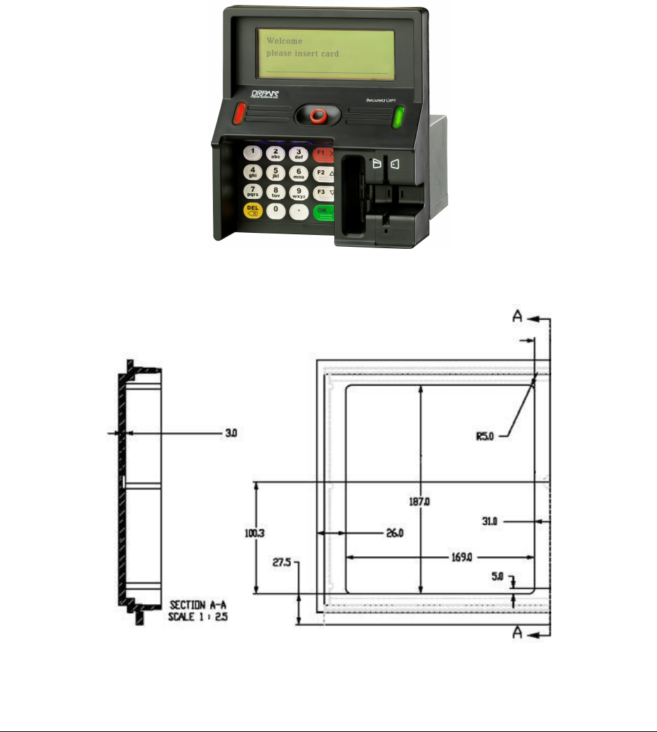
1-2.1. Secured OrPT Housing
Secured OrPT enclosure is made of a plastic-molded front panel, and an aluminum rear casing (see
Figure 1-1). The enclosure is weather-proof in order to sustain the harsh outdoor environments
when installed in an outdoor enclosure. The front panel of the OrPT is made of rugged plastic. The
devices front is sealed.
Figure 1-2 depicts the enclosure dimensions of the opening required for installing the Secured OrPT
into 3
rd
party panels.
Figure 1-1. Secured OrPT – General View
Figure 1-2. Secured OrPT – Enclosure Opening Dimensions

Secured OrPT Single Box Installation Manual
3
1
1-
-3
3.
.
P
PR
RI
IN
NT
TE
ER
R
S
SP
PE
EC
CI
IF
FI
IC
CA
AT
TI
IO
ON
NS
S
Table 1-2 displays the physical, electrical and environmental specifications applicable to the
Printer.
Table 1-2. Printer Specifications
Supply Voltage: 24 VDC
Power Consumption:
Maximum standby current
Maximum current
Standby 15 W.
Typical 60 W (without heater).
0.625 A
2.5 A
Dimensions (HxWxD): 110.2 x 178.4 x 100 mm
Operating Temperature: -5 °C to +55°C (-40°C to +55°C with optional heater)
Storage Temperature: -20 °C to +70 °C
Communication Interface: RS-485 – 9600 bps Half-Duplex
Paper Type: 40m x 57 mm (L x W)
55 gr. – thermal
Paper Maximum Printing Area
Width:
54 mm
Maximum Printing Speed: 120 mm/sec.
Paper cutter: Integrated, Full cutter, Automatic
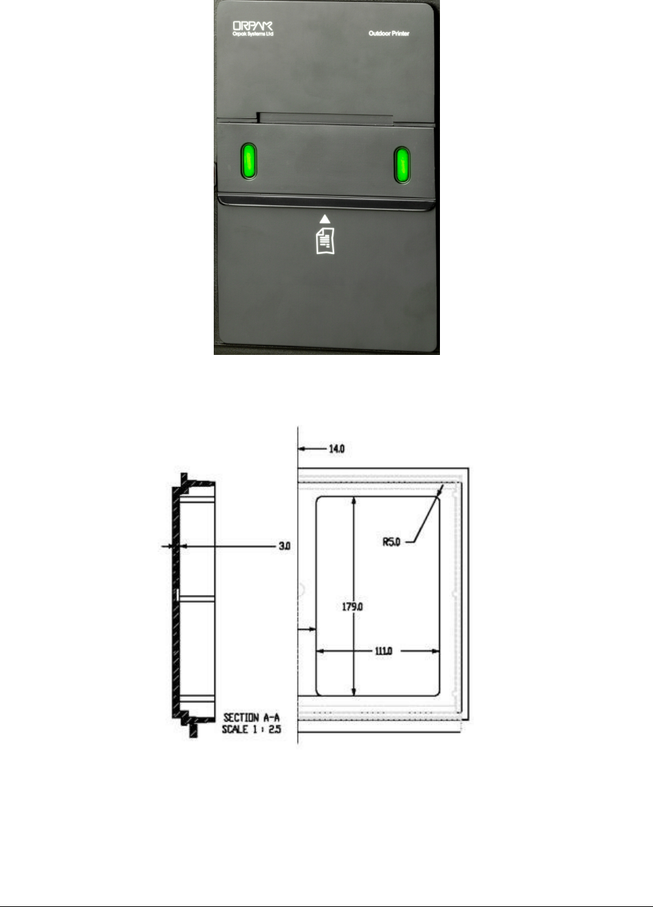
1-3.1. Printer Housing
The Printer module enclosure is made of aluminum (see Figure 1-3.). The front panel includes two
green LED indicators and the receipt aperture, protected behind a metal lid. The printer lock is an
electro-mechanic lock (Solenoid type) controlled by the Station Controller/POS.
Figure 1-4 depicts the enclosure dimensions of the opening required for installing the G2 Printer
into 3
rd
party panels.
Secured OrPT Single Box Installation Manual
4
Figure 1-3. G2 Printer – General View
Figure 1-4. G2 Printer – Enclosure Opening Dimensions

Secured OrPT Single Box Installation Manual
5
1
1-
-4
4.
.
V
VO
OL
LT
TA
AG
GE
E
P
PR
RO
OT
TE
EC
CT
TI
IO
ON
N
Secured OrPT and Printer housing requires a grounding attachment, i.e. the devices should be
connected to the dispenser (in case of retrofit in petroleum environments) for protection against
high voltage transient and lightning.
Furthermore, two types of protections are included in the devices:
• Isolation of 1.5 KVDC to protect against galvanic connection between the host side and the
device side.
• In RS-485 communication, the terminal side is protected against high voltage transient and
lightning by using Spark Gaps and transorbs. This allows the use of long communication
cables.

Secured OrPT Single Box Installation Manual
6
S
SE
EC
CT
TI
IO
ON
N
2
2
S
SI
IN
NG
GL
LE
E
B
BO
OX
X
I
IN
NS
ST
TA
AL
LL
LA
AT
TI
IO
ON
N
2
2-
-1
1.
.
G
GE
EN
NE
ER
RA
AL
L
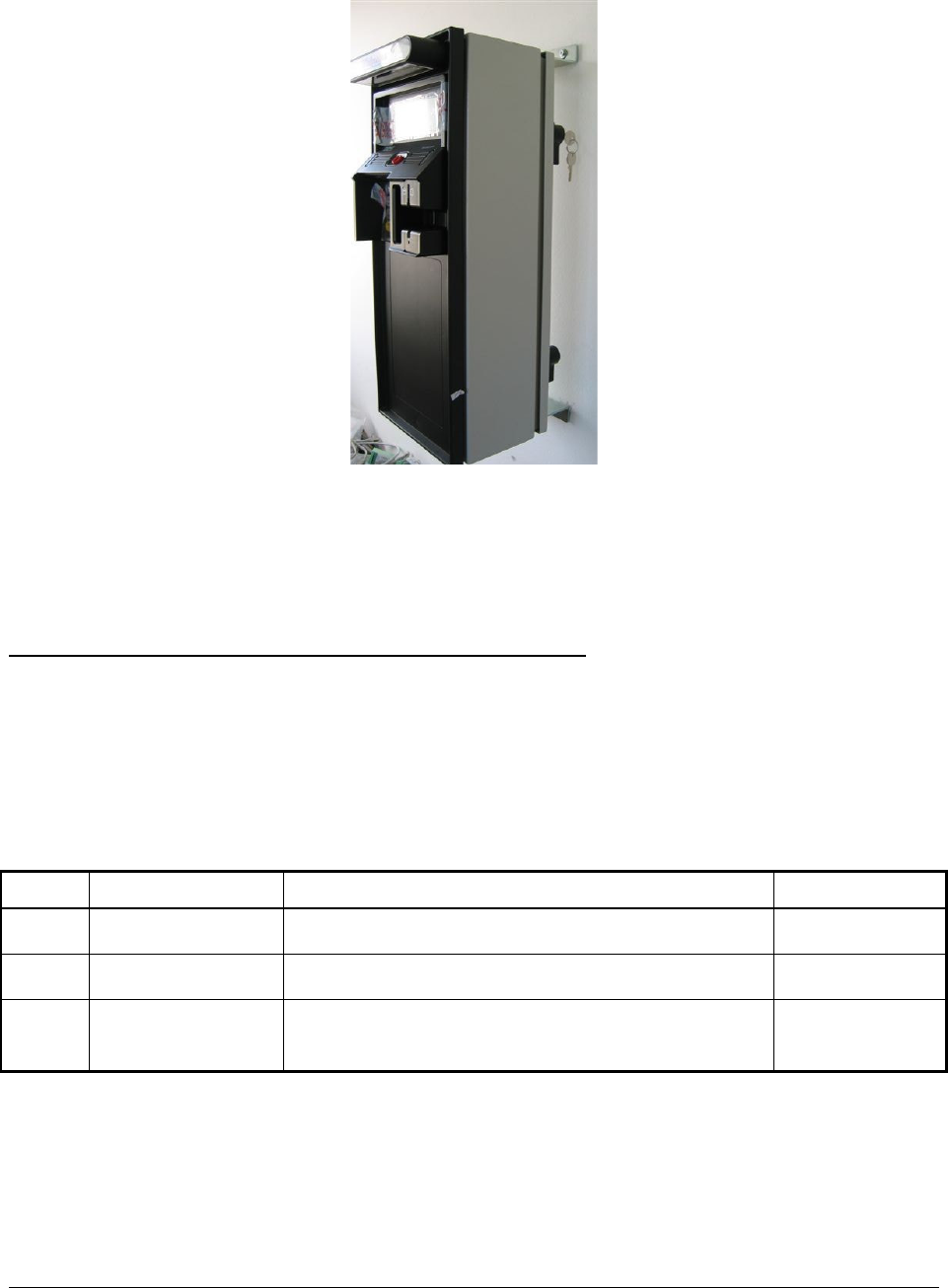
The single box configuration takes into consideration the ease of use of the user related equipment.
The front panel of the Secured OrPT faces the attendant and the driver, and the printer is located
below the keyboard.
This section provides instructions for installing the Secured OrPT & Printer Single Box on its pole
(accessory, see Figure 2-1) or on the wall (see Figure 2-2).
Figure 2-1. Secured OrPT Single Box – Pole Installation
Secured OrPT Single Box Installation Manual
7
Figure 2-2. Secured OrPT Single Box – Wall Mounted
2
2-
-2
2.
.
C
CO
OM
MP
PO
ON
NE
EN
NT
TS
S
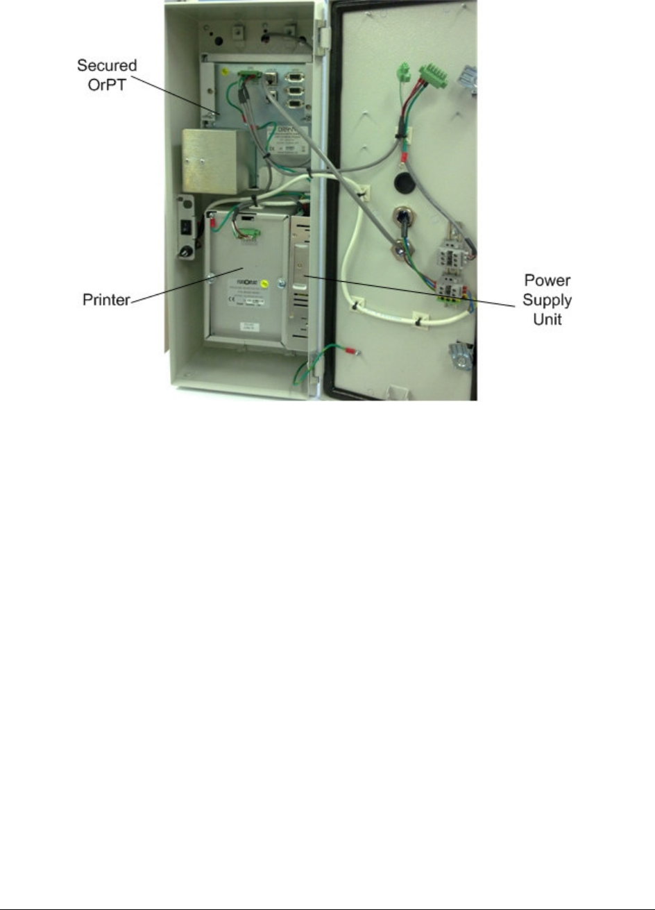
Table 2-1 defines the Secured OrPT Single Box components (see Figure 2-3 for the location of the
main components within the box). Communication link is obtained either directly from the LAN, or
via the RS-485 link.
The Secured OrPT Single Box components are interconnected within the box by an RS-485 link.
Table 2-1. Secured OrPT Single Box Components
No. Function Module Type Quantity
1. Payment terminal Secured OrPT – P/N 800926100-800926299 1
2. Printer Outdoor printer (G2 model) - P/N 800919900 1 (Optional)
4. Power Supply 100-220 VAC input; 75W, 24 VDC output, power
supply unit - P/N 811308210
1
Secured OrPT Single Box Installation Manual
8
Figure 2-3. Secured OrPT Single Box Components Location
2-2.1. Single Box Specifications
Table 2-2 displays the physical, electrical and environmental specifications applicable to the
Secured OrPT Single Box.
Table 2-2. Secured OrPT Single Box Specifications
Supply Voltage: 100-220 VAC
Maximum current (230VAC)
Maximum current (115 VAC)
1.2 A
2 A
Operating Temperature: -5°C to +60°C (optional -40°C to +60 °C with internal
heater)
Storage Temperature: -20 °C to +70 °C
Humidity: 80% Non-condensing
Communication Interface: RS-485 – 9600 bps Half-Duplex
Ethernet RJ-45 10 Mbps (x2)
Dimensions H 505 mm X W 200 mm X D 160 mm

Secured OrPT Single Box Installation Manual
9
2
2-
-3
3.
.
I
IN
NS
ST
TA
AL
LL
LI
IN
NG
G
S
SE
EC
CU
UR
RE
ED
D
O
Or
rP
PT
T
P
PA
AN
NE
EL
L
&
&
P
PR
RI
IN
NT
TE
ER
R
I
IN
N
T
TH
HE
E
S
SI
IN
NG
GL
LE
E
B
BO
OX
X
The following instructions provide the procedures for the installation of the Secured OrPT & Printer
modules in the Single Box. The Single Box is delivered fully installed, thus no further installation is
required. Use these instructions only for replacing the unit, due to a malfunction or unit upgrade.
The Secured OrPT installation procedures consist of two main steps:
• Mechanical installation of the Secured OrPT inside the Single Box using the holder
• Connecting the Secured OrPT cables in the Single Box
2-3.1. Wiring
Table 2-3 and Table 2-4 list the different types of Single Box internal cables to be connected to the
Secured OrPT and to the G2 Printer during installation.
Table 2-3. Secured OrPT Internal Wiring
Cable Type Function/
Connection
Termination Note
Communication &
Power
Connects Secured OrPT
to RS-485 &Power
RS-485 comm.
connector
Shielded CAT-5 Connects Secured OrPT
to Ethernet
Hub/Switch inside or
outside the Single Box.
Only in Ethernet
connectivity
Ground single wire
Connection to earth for
surge protection
Ring connector with
Phillips screw
Connected to Secured
OrPT box chassis
(Thread M3)
Table 2-4. G2 Printer Internal Wiring
Cable Type Function/
Connection
Termination Note
Communication &
Power
Connects printer to
RS-485/Power harness
6-pin green connector
(P/N 813326106)
Ground single wire
Connection to earth for
surge protection
Ring connector with
Phillips screw
Connected to printer box
chassis (Thread M3)
Secured OrPT Single Box Installation Manual
10
2-3.2. Secured OrPT & Printer Installation
Perform the following procedures for installing the Secured OrPT and the printer in the Secured
OrPT Single Box:
1. Prepare a comfortable place to perform the installation, which will allow easy access to the
Secured OrPT Box
2. Disconnect all power sources to the Single Box and in installation area
3. Insert the Secured OrPT Panel to its designated aperture in the Single Box (see Figure 2-3)
4. Place the spacers on the protruding screws on the rear side of the Secured OrPT
5. Place the Secured OrPT Panel holder on top of the spacers
6. Close the Secured OrPT Panel holder using two wing screws
7. Connect the applicable cables to the Secured OrPT in accordance with the connectors'
description given on paragraph 2-3.1
8. Connect the grounding cord to the designated screw in the Secured OrPT Panel (near the
center of the panel)
9. Insert the printer into the designated aperture in the Single Box (see Figure 2-3)
10. Secure the printer using the clamp housing, two flat washers, two spring washers and two
wing screws
11. Connect the applicable cables to the Secured OrPT in accordance with the connectors'
description given on paragraph 2-3.1
12. Connect the grounding cord to the designated screw in the Printer (on the upper left corner
on the rear panel)
2
2-
-4
4.
.
I
IN
NS
ST
TA
AL
LL
LI
IN
NG
G
S
SE
EC
CU
UR
RE
ED
D
O
OR
RP
PT
T
S
SI
IN
NG
GL
LE
E
B
BO
OX
X
&
&
P
PR
RI
IN
NT
TE
ER
R
O
ON
N
T
TH
HE
E
P
PO
OL
LE
E
2-4.1. General
Orpak offers a standard pole, P/N 814921650, or an adjustable pole, P/N 819038025, on which the
Secured OrPT Single Box can be mounted. Installation instructions are provided below. However,
the customer should develop installation plans for each specific installation.
N
NO
OT
TE
E
Perform a site survey of the site prior to installation.
For further information, contact Orpak Technical
Support.

Secured OrPT Single Box Installation Manual
11
The customer should provide an installation plan, designed by an authorized engineer, and
applicable to all authorities having jurisdiction. This plan design should reflect the existing electric
infrastructure of the site.
Regardless of the installation plan, the safety precautions and installation requirements, detailed
in the following paragraphs, must be conformed to.
Figure 2-4. Secured OrPT Single Box – Installation Pole P/N 819038022
2-4.2. Safety Distances
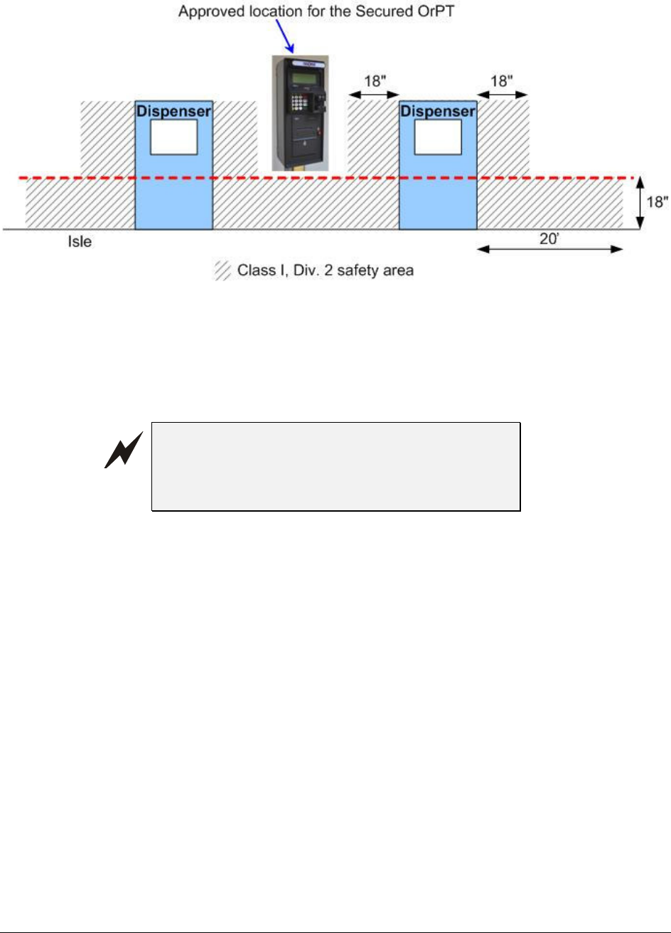
The Secured OrPT is suitable for use over Class 1, Division 2. Figure 2-5 shows the safety
distances required for the installation of the Secured OrPT in a non hazardous location adjacent
to the dispensers. When mounting the Secured OrPT, a minimum clearance of 18 inches
between the unit and any of the pumps or the dispensers must be maintained. This clearance
allows room for the wiring and maintenance of the system.
Secured OrPT Single Box Installation Manual
12
Figure 2-5 Secured OrPT – Installation Control Drawing
2-4.3. Precautions and Safety Notes
Prior to actual installation activities, carefully observe the precautions and safety notes below.
W
WA
AR
RN
NI
IN
NG
G
Before installing or servicing equipment, carefully
observe the warnings and precautions in the
beginning of this manual.
Remember that the fuel station environment is highly flammable and combustible. Therefore,
make sure that actual installation is performed by experienced personnel, licensed to perform
work in fuel stations and capable of implementing all applicable requirements of the National
Fire Protection Association NFPA-30 “Flammable and Combustible Liquids Code”, NFPA-
30A “Automotive and Marine Service Station Code”, NFPA-70A “National Electric Code”,
federal, state and local codes and any other applicable safety codes and regulations.
Remember that high quality installation will ensure correct system operation and user safety:
- All installed wiring must conform with all building/fire codes, all Federal, State and Local
codes and regulations, the National Electrical Code (NFPA 70), NFPA 30, and the
Automotive and Marine Service Station Code (NFPA 30A).
- Use only threaded, rigid, metal conduits.
- Use only UL-approved correctly sized insulated gasoline and oil-resistant copper wiring.
- Unit power should be supplied from a dedicated circuit breaker (6A). No other equipment
should be powered from this breaker.

Secured OrPT Single Box Installation Manual
13
- System power may come from more than one source. Disconnect all power sources before
attempting to work on the system.
Install the Secured OrPT Single-Side Box only in non-hazardous locations.
Do not connect power to the device until complete station installation is inspected and certified.
Do not perform any metal work in the hazardous area. Sparks generated by drilling, tapping
and metal work operations could ignite fuel vapors and flammable liquids, resulting in death,
serious personal injury, property loss and damage to you and other persons.
When working in any open area of fuel station, beware of passing vehicles that could hit you.
Block off the work area to protect yourself and other persons. Use safety cones or other
signaling devices.
2-4.4. Installation Requirements
When installing the Secured OrPT Single Box, conform to the following requirements:
As the units inside the Single Box require interaction with people, install the Box in a
convenient place and height for allowing easy access to the Secured OrPT panel and the
Outdoor Printer.
Avoid proximity to heat sources such as vents from air conditioners, heat dispersal ducts, etc’.
Avoid exposure of the Secured OrPT Single Box to direct sunlight.
Verify that the cable lengths are sufficient to your installation location.
Install the Secured OrPT & Printer in a non hazardous area according to Figure 2-5.
• The installation procedures must meet all safety regulations according to local state regulations.
• For UL listed Secured OrPT, all wiring to device must be in UL listed rigid metal conduit or
other methods permitted in NFPA 70 or NFPA 30A determined acceptable by the authority
having jurisdiction
• For non-UL Secured OrPT, glands are provided for the power and data openings
2-4.4.1. Conduits Sealing
The conduits shall be sealed in accordance with NFPA requirements and local regulations, to
prevent the passage of gases through conduits, cables and conductors. The fittings are requested
wherever volatile liquids or gases are present in the surroundings (see Figure 2-6).
Secured OrPT Single Box Installation Manual
14
Figure 2-6 Conduit Fitting
2-4.5. Preliminary Pole Installation Instructions
Perform the following preliminary instructions (see Figure 2-7):
N
NO
OT
TE
E
Perform a site survey of the station prior to
installation. For further information, contact Orpak
Technical Support.
1. Obtain an installation plan, designed by an authorized engineer, and applicable to all
authorities having jurisdiction
2. Ensure that this plan design reflects the existing electric infrastructure of the site
3. Run cable conduits for power and communication cables to the spot for the installation of
the pole of the single Secured OrPT Single Box
4. Prepare Installation Plate with four ICU bolts attached with M10 nuts. Check that the bolts
protrude from the plate by 35 mm
5. Dig a hole on the ground of:
Width x Length x Depth – 300 x 300 x 400 mm
6. Insert Installation Plate in the hole
7. Take care that the power and communication cable conduits pass through the central hole in
the Installation Plate
8. Pour concrete type B200 in the hole as a support base for the pole

Secured OrPT Single Box Installation Manual
15
9. Take care that, as the concrete fills the hole, the Installation Plate is on a same level as the
ground (asphalt, pedestal) on which it is installed. Check repeatedly that the Installation
Plate is leveled otherwise make the necessary adjustments so the plate is perfectly leveled
10. Wait the necessary time for the concrete to harden and dry (as per local practice), Check
anew that the Installation Plate is leveled.
2-4.6. Pole Installation Instructions
Perform the following Pole installation instructions (see Figure 2-7):
1. Remove the four M10 nuts from the four ICU bolts attached to the Installation Plate
2. Insert Pole on top of the Installation Plate
3. Secure Pole on the Installation Plate to the Installation Plate to the four installation threads
in the inner ground area of the Pole
4. Secure the Installation Plate with four M10 spring washers, M10 washers and M10 nuts
5. Insert right and left Rozetas on the Installation Plate, and secure to Pole with two flathead
M3x10 screws
This completes the installation of the Pole for the Secured OrPT Single Box. Proceed with the
installation of the Secured OrPT Single Box.
2-4.7. Single Box Pole Installation Instructions
Perform the following Single Box Pole installation instructions (see Figure 2-7 and Table 2-5):
1. Pull out power and communication cable conduits from the Pole
2. Open Single Box door, use the dedicated key if it is locked
3. Insert the cables to be connected to the Single Box. All wiring to the device must be done in
UL listed rigid metal sealed conduit, at least 18'' higher than surface
4. Install the Single Box on the upper installation flange of the Pole
5. Secure the Secured OrPT Single Box to the Pole with four M6 flat plastic washers (for
waterproof purpose), four M6 flat washers, four M6 spring washers and four M6x16 screws
6. Connect the power and communication cables to the Single Box.
7. Lock the Secured OrPT Single Box door using the provided key
Secured OrPT Single Box Installation Manual
16
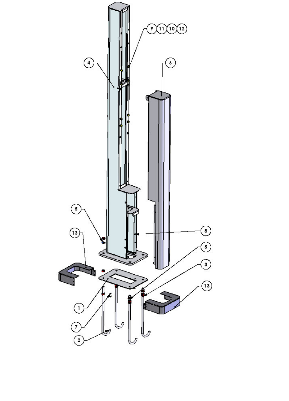
Figure 2-7. Single Box – Pole Set, P/N 819038022

Secured OrPT Single Box Installation Manual
17
Table 2-5. Secured OrPT Single Box – Pole, Single Box, Installation Assembly Parts
Item N o.
Part Number Description Qty
1 814921800 Installation Plate 1
2 814906200 Bolt, ICU 4
3 815103000 Nut, M10 12
4 814921650 Pole, In House 1
5 815300700 Spring Washer M10 4
6 814921670 Pole, Long Cover 1
7 815201900 Screw, M3x10 Flat HD Cross Reces 4
8 815203200 Screw, F/H M4 x 10 4
9 815216200 Screw, M6x16 Pan HD CROSS Reces 8
10 815303100 Washer, Spring, M6 8
11 815322200 Washer, Flat, M6 8
12 815330300 Washer, Flat, Plastic, M6 8
13 814921700 Rozeta, Right\Left, Pole, 2
Secured OrPT Single Box Installation Manual
18
2
2-
-5
5.
.
S
SI
IN
NG
GL
LE
E
B
BO
OX
X
W
WA
AL
LL
L
I
IN
NS
ST
TA
AL
LL
LA
AT
TI
IO
ON
N
I
IN
NS
ST
TR
RU
UC
CT
TI
IO
ON
NS
S
Perform the following Single Box wall installation instructions (see Figure 2-8, Figure 2-9 and
Figure 2-10, and refer to Table 2-6):
1. Bring power and communication cable conduits to the installation spot on the wall. All
wiring to the device must be done in UL listed rigid metal sealed conduit
2. Attach two installation brackets to the Single Box using M6X16 screws, M6 flat washers
and M6 plastic washers and secure each flange with M6 washers, M6 spring washers and
M6x16 nuts on the top and bottom of the single box
3. Open Single Box door , use the dedicated key if it is locked
4. Insert cables in the Single Box to be installed
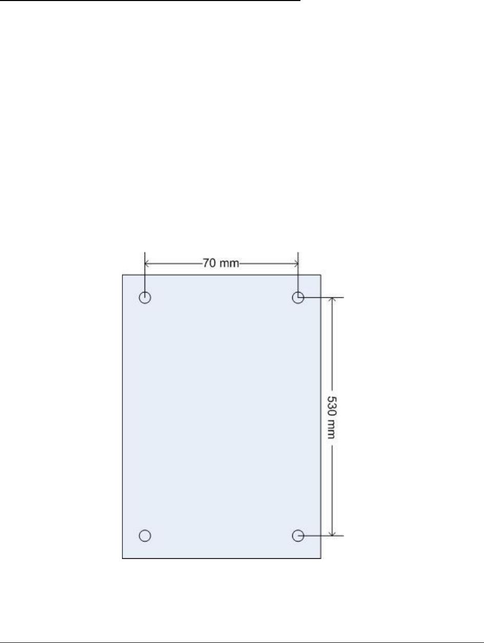
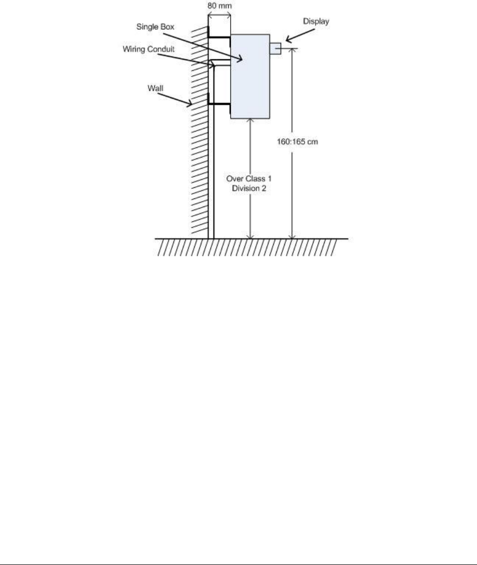
5. Locate the exact spot on the wall for the installation of the Single Box, and mark spots for
holes drilling (see dimensions in Figure 2-8) – while allowing a distance of 160 to 165 cm
from the center of the display to the ground, as shown below
6. Drill four holes for M6x74 anchor dibbles
Figure 2-8. Single Box Wall- Mounted Perforation's Dimensions
Secured OrPT Single Box Installation Manual
19
7. Install the Single Box on the wall
8. Secure the Single Box to the wall with four M6x74 anchor dibbles
9. Lock the Secured OrPT Single Box door with the provided Key
10. Connect the power and communication cables inside the Single Box
Figure 2-9. Single Box Wall-Mounting Installation Instructions
Secured OrPT Single Box Installation Manual
20
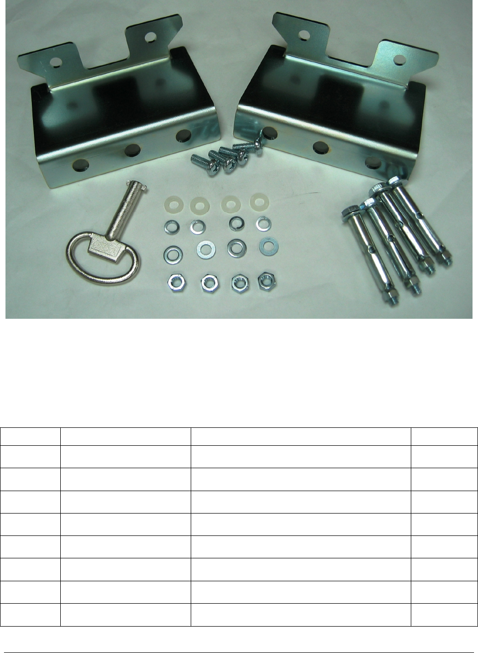
Figure 2-10. Single Box –Installation Kit (Optional) for Wall Mount Installation, P/N
819022519
Table 2-6. Single Box –Installation Assembly Part List for Wall Mount Installation
Item N o. Part Number Description Qty
1 813100010 Key, Double-bit, 2531, Rittal, 90d 1
2 814423300 Wall Mounting, Bracket, Single 2
3 815000200 Dibble, AB10/15, m6x74, (anchor) 4
4 815103200 Nut, m6, Din934, Iso4033 4
5 815216200 Screw, m6x16 Pan Hd Cross Recs 4
6 815303100 Washer, Spring,m6, D-7980, Palbor 4
7 815322200 Washer, flat, m6 4
8 815330300 Washer, flat, Plastic, m6 4