Orpak Systems 819507410 UDATAPASS User Manual
Orpak Systems Ltd. UDATAPASS Users Manual
Users Manual

FCC Compliance Statement for DataPass/µDataPass
1
D
Da
at
ta
aP
Pa
as
ss
s
&
&
µ
µD
Da
at
ta
aP
Pa
as
ss
s
D
De
es
sc
cr
ri
ip
pt
ti
io
on
n
&
&
I
In
ns
st
ta
al
ll
la
at
ti
io
on
n
1.1. SCOPE
This section includes a general and functional description of the DataPass and
installation procedure.
1.2. DATAPASS & µDATAPASS DESCRIPTION
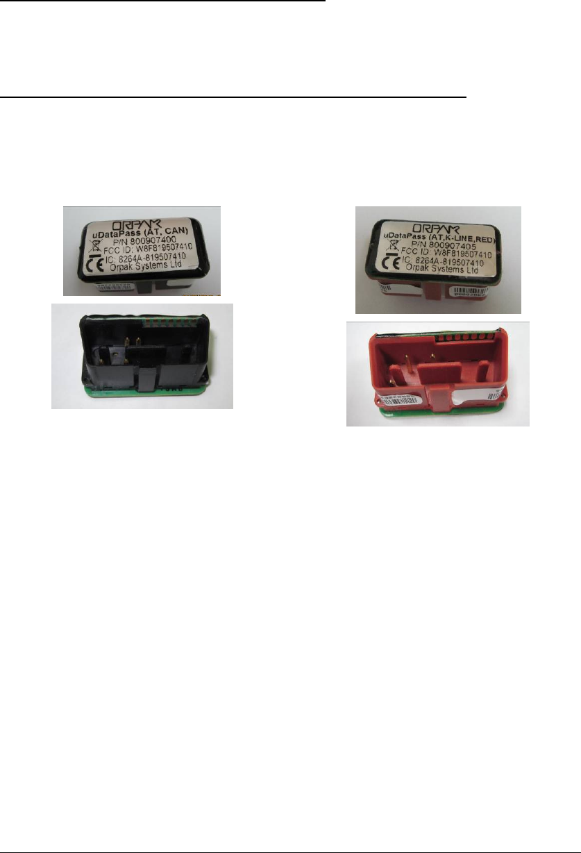
DataPass and µDataPass are miniature units connecting to the vehicle bus and capture
data from the vehicle CPU/BUS. They then transmit this data to the nearest Wireless
Gateway in the forecourt. Two unit types are available for the installer (see Figure
0-1. µDataPass or Figure 0-2. DataPass):
µDataPass (CAN) for CAN Bus protocol,
Cat. No. 800907400
µDataPass (k-line) for K-
line protocol,
Cat. No. 800907405
Figure 0-1. µDataPass
µDataPass – a connector shaped unit that plugs into the vehicle On Board
Diagnostics connector (OBD II) and intended for light and commercial vehicles which
has OBD II connector. µDataPass has two versions:
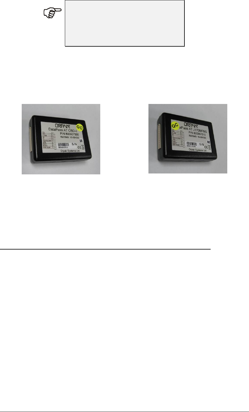
DataPass - connected directly to the vehicle bus harness and is used in heavy and
light vehicles and supports most bus protocols common to those vehicles.
DataPass unit supports vehicle protocols (this manual deals with k-line and
CanBus protocols:
There are two types of devices:
DataPass for light vehicles (OBD), Cat No. 800907300
DataPass (J1708/FMS) for heavy vehicles, Cat No. 800907310

FCC Compliance Statement for DataPass/µDataPass
2
N
NO
OT
TE
E
Please check the manufacturer
specifications for the proper protocol
supported by the Vehicles in your
fleet!
The System comprises several parts installed in various configurations as follows (see
Figure 0-2):
• DataPass Harness – used in conjunction with the DataPass; it connects the
DataPass to the Diagnostics plug rear wiring in heavy vehicles.
DataPass for light vehicles (OBD-II), Cat No.
800907300
DataPass (J1708/FMS) for heavy vehicles, Cat
No. 800907310
Figure 0-2. DataPass
1.3. DATAPASS – TECHNICAL SPECIFICATION
1.3.1. Communication
Wireless Interfaces
Single IEEE802.15.4 wireless channel
Operating Frequency ISM 2.405 to 2.480 GHz (Global license free band)
Implements proprietary Mesh network
IEEE802.15.4 Modem
DSSS/FA - Direct Sequence Spread Spectrum with Frequency Agility
Supported network topologies –Propriety Mesh network
Channel capacity – 16 frequency channels / 5MHz channel spacing
Transmit power output – 2mW (3dbm)
Receive sensitivity – (-101dbm)
Wireless Antenna
Built in PCB Antenna

FCC Compliance Statement for DataPass/µDataPass
3
Wired Interfaces
OBDII – J2284/ISO15765 (CAN BUS)
OBDII – ISO14230/ISO9141 (KLINE)
1.3.2. Electrical
Supply Voltage
Normal operation: 12VDC (Nominal)
Minimum 10 VDC
Maximum 32 VDC
Current Consumption (typical)
KLINE Mode:
•
In sleep mode - 4mA
•
In active mode - 35mA
CAN Mode:
•
In sleep mode - 4mA
•
In active mode - 25mA
1.3.3. Mechanical
Dimensions
70 x 22 x 17 mm (W x H x D)
Weight
10 grams
Connectors
OBDII compatible (male)
1.3.4. 5. Environmental Conditions
Temperature Range
Operating: -40 to +70 ºC
Storage: -40 to +85 ºC

FCC Compliance Statement for DataPass/µDataPass
4
FCC COMPLIANCE STATEMENT IN USER'S MANUAL
This device complies with part 15 of the FCC rules. Operation is subject to the
following two conditions:
(1) This device may not cause harmful interference, and
(2) This device must accept any interference received, including interference that may
cause undesired operation.
Sample user information for a Class A digital device:
THE FCC WANTS YOU TO KNOW
:
This equipment has been tested and found to comply with the limits
or a Class A digital device, pursuant to part 15 of the FCC Rules. These
limits are designed to provide reasonable protection against harmfulinterference
when the equipment is operated in a commercial environment.
his equipment generates, uses, and can radiate radio frequency energy
and, if not installed and used in accordance with the instruction manual,
ay cause harmful interference to radio communications. Operation of this
equipment in a residential area is likely to cause harmful interference in
which case the user will be required to correct the interference at his
own expense.
FCC Warning
Modifications not expressly approved by the manufacturer responsible could void
the user’s authority to operate the equipment under FCC rules.

FCC Compliance Statement for DataPass/µDataPass
5
Sample user information for a Class B digital device
THE FCC WANTS YOU TO KNOW
:
This equipment has been tested and found to comply with the limits
for a Class B digital device, pursuant to part 15 of the FCC Rules. These
limits are designed to provide reasonable protection against harmful
interference in a residential area.
This equipment generates, uses, and can radiate radio frequency energy
and, if not installed and used in accordance with the instructions,
may cause harmful interference to radio communications. However, there
is no guarantee that interference will not occur in a particular installation.
if this equipment does not cause harmful interference to radio or television
reception, which can be determined by turning the equipment off and on,
the user is encouraged to try to correct the interference by one or more of
the following measures:
Reorient or relocate the receiving antenna
Increase the separation between the equipment and the receiver
Connect the equipment to an outlet on a circuit different from that
to which the receiver is connected
Consult the dealer or an experienced radio/TV technician
FCC Warning
Modifications not expressly approved by the manufacturer responsible
could void the user’s authority to operate the equipment under FCC rules.
WARNING
Removal of the epoxy covering will damage the radio circuitry and the
device will cease to function and the product will be destroyed.
Removal of the epoxy covering will void any guarantees made by
Orpak Systems Ltd. concerning µDataPass.