Orthosensor ORTHOSNSR7 Arthroplasty force sensor User Manual LB 5135 VERASENSE IFU for US and OUS Rev 1 TUV 12jun18b
Orthosensor, Inc Arthroplasty force sensor LB 5135 VERASENSE IFU for US and OUS Rev 1 TUV 12jun18b
LB-5135 VERASENSE IFU for US and OUS-Rev_1-TUV-12jun18b
OrthoSensor, Inc.
1855 Griffin Road
Suite A-310
Dania Beach, FL 33004-2200 USA
www.orthosensor.com
LB-5135 Rev. 1 (EN) 1
06-2018
For further information, contact the OrthoSensor Customer Service Center by phone at + 1 954-577-7770 or by e-mail
at customerservice@orthosensor.com or go to www.orthosensor.com.
VERASENSE INSTRUCTIONS FOR USE
DESCRIPTION
VERASENSE provides a means to dynamically balance the knee during primary or revision Total Knee Arthroplasty (TKA).
The VERASENSE device is an intelligent disposable tibial insert that measures dynamic loads in the medial and lateral
compartments of the knee and wirelessly transmits the measured load data to the LinkStation MINI or LinkStation MINI
Evaluation Kit with VERASENSE Software Application (VSA) installed for surgeon visualization. Individual VERASENSE devices are
packaged sterile, for single patient use with a Shim Set for thickness adjustments.
NOTE: The following accessories are necessary for the operation of the VERASENSE device:
• LinkStation MINI or LinkStation MINI Evaluation Kit
• VERASENSE Software Application (VSA)
The LinkStation MINI and LinkStation MINI Evaluation Kit displays the measured load data by providing a graphical and
numerical presentation of the loads in both the medial and lateral compartments of the knee.
VERASENSE devices are implant system specific due to variations in implant design. VERASENSE is compatible with the
following implant systems:
• VERASENSE for Biomet Vanguard
• VERASENSE for Stryker Triathlon
• VERASENSE for Zimmer NexGen
• VERASENSE for Smith & Nephew Legion
• VERASENSE for Smith & Nephew Journey II
• VERASENSE for Zimmer Biomet Persona
Please see Table 3 for the listing of Catalog Numbers for each compatible implant system and sizes.
INDICATIONS
VERASENSE is indicated for any medical condition in which primary or revision Total Knee Arthroplasty (TKA) would be
indicated.
For use as a tool for adjustment of the femoral knee implant to reduce instability from flexion gap asymmetry. VERASENSE is
sterile, for single patient use.
CONTRAINDICATIONS
• Any active or suspected latent infection in or about the knee joint.
• Refer to Implant Knee System IFU for additional contraindications.
PRECAUTIONS
• Read and follow instructions for proper use and interpretation of force data displayed.
• Strict adherence to the indications, contraindications, precautions and user/patient safety for this product is essential.
• Refer to appropriate implant knee system IFU for additional precautions.
• Data from VERASENSE is for reference purposes only and should not be the sole basis for surgical decisions.
• The internal components of the VERASENSE device are non-sterile. Immediately discontinue use of device if any cracks,
damage, or internal fluid is observed. Failure to observe these warnings may expose patient to non-sterile material.
• The VERASENSE device consists of sophisticated calibrated internal microelectronics. Do NOT directly impact with mallet or
other instruments at any time.
OrthoSensor, Inc.
1855 Griffin Road
Suite A-310
Dania Beach, FL 33004-2200 USA
www.orthosensor.com
LB-5135 Rev. 1 (EN) 2
06-2018
For further information, contact the OrthoSensor Customer Service Center by phone at + 1 954-577-7770 or by e-mail
at customerservice@orthosensor.com or go to www.orthosensor.com.
• Handle VERASENSE device with care when inserting, adjusting shim size or removing from tibial tray.
• Do not forcibly impact femoral implant trial onto the VERASENSE device placed in tibial tray.
• Do not attempt to use the VERASENSE device without selection and use of proper shim and appropriate sized tibial tray.
• When detaching a shim from the VERASENSE device, detach anterior lip first, do not pry off posterior edge.
o Note: For the VERASENSE for Zimmer Biomet Persona, detach shim by prying on the posterior edge.
• Federal law restricts this device to sale by or on the order of a licensed physician.
USER/PATIENT SAFETY
• VERASENSE device and shim sets are supplied as single-use sterile. Do not reuse or re-sterilize.
• If VERASENSE device or shim set packaging is open or damaged, do not use and immediately return to OrthoSensor.
• Do not use VERASENSE device after the expiration date on the package labeling.
• Do not use the VERASENSE device without a shim attached in the tibial tray for the VERASENSE for Stryker Triathlon Sizes 3-6,
VERASENSE for Biomet Vanguard, or VERASENSE for Zimmer Biomet Persona devices.
• Maximum allowable load for the VERASENSE device is 70 lbf per compartment. If the physician perceives a difference
between the loads displayed on the screen and the physical feel, the physician should either replace the device or continue
the procedure using their standard instrumented trial technique and best clinical judgment.
o Note: Load values between 41-70 lbf are displayed for reference only.
• Do not impact / hit the VERASENSE device or any objects in contact with the device as this may result in damage to its
exterior casing.
• Do not use a prying device during surgical procedure while the VERASENSE device is in place as this may result in damage to
the exterior of the device.
• The VERASENSE device contains non-sterile, non-medical grade internal components. If the device housing is damaged or
cracked during the procedure, take appropriate steps to promote patient safety.
• Do not disassemble or otherwise modify the VERASENSE device or shims.
• Do not use VERASENSE device if it appears to be functioning improperly.
• Observe all warnings generated by the VERASENSE Software Application.
INSTRUCTIONS
1. Confirm the LinkStation MINI or LinkStation MINI Evaluation Kit is setup appropriately outside of the sterile field.
Refer to the VERASENSE User Guide or VERASENSE Quick Reference Guides. The LinkStation MINI or LinkStation MINI
Evaluation Kit is located outside of the sterile field and the VERASENSE device and shims are used within the sterile
field.
2. Determine the specific implant type and size VERASENSE device required. Remove pouched Shims and device from
the box. DO NOT OPEN POUCH SEALS.
a. Do not use if device or shim set packaging has been opened or damaged.
3. Record VERASENSE device serial number ( ) onto patient and hospital records as required.
4. To activate the VERASENSE device:
a. With the product still in the sealed pouches, place the device directly over the magnet on LinkStation MINI
or LinkStation MINI Evaluation Kit. An LED light will illuminate on the device. Do not move the device until
you observe the following:
i. LED turns off after approximately four (4) seconds.
ii. VERASENSE Software Application launches.
iii. Initialization progress bar appears and completes.
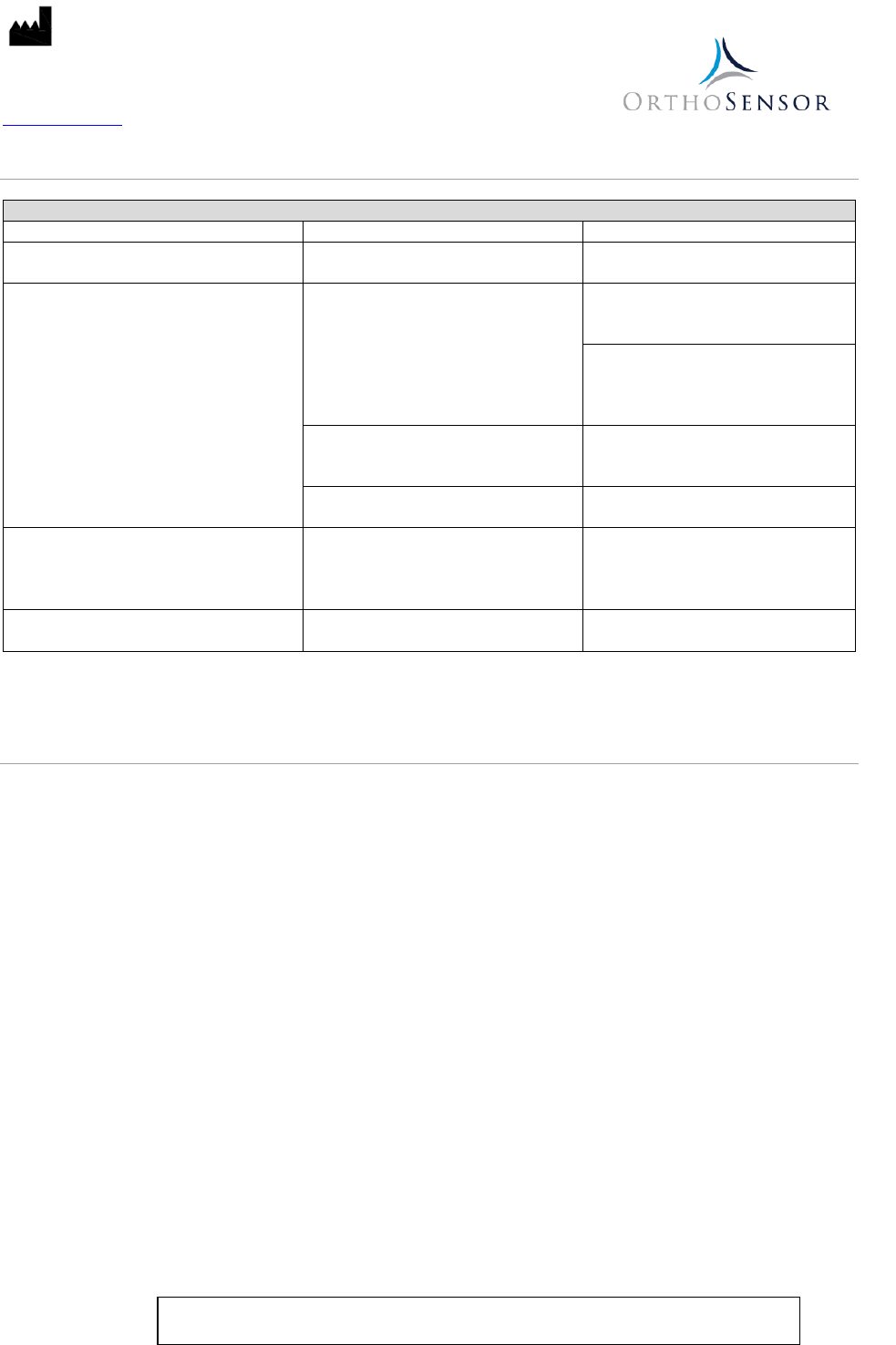
Model Measurement Load Range Load Accuracy
VERASENSE for Biomet Vanguard
5-40 lbf per compartment
±3.5 lbf
VERASENSE for Stryker Triathlon
VERASENSE for Zimmer NexGen
VERASENSE for Smith & Nephew Legion
VERASENSE for Smith & Nephew Journey II
VERASENSE for Zimmer Biomet Persona
OrthoSensor, Inc.
1855 Griffin Road
Suite A-310
Dania Beach, FL 33004-2200 USA
www.orthosensor.com
LB-5135 Rev. 1 (EN) 3
06-2018
For further information, contact the OrthoSensor Customer Service Center by phone at + 1 954-577-7770 or by e-mail
at customerservice@orthosensor.com or go to www.orthosensor.com.
iv. Prompt to select left or right leg appears.
b. Device may now be removed from magnet.
5. The VERASENSE Software Application will automatically prompt selection of left or right leg. Select the appropriate
operative leg.
6. Zero Device
a. Follow on screen instructions to zero the VERASENSE device.
7. Upon completion of the device initiation process as prompted on the VERASENSE Software Application, pass the
sealed pouches to the nurses within the sterile field of the operating room.
8. Open double sealed pouches per hospital protocol (VERASENSE device and shim set).
9. With the VERASENSE device and shims removed from the pouches, apply designated shim to underside of VERASENSE
device.
Note: The VERASENSE for Zimmer Biomet Persona device shim attaches to the top of the device. Attach by
inserting the devices anterior tab into the anterior loop on the shim, engage the posterior snapping
mechanism by squeezing the assembly together. Input the selected shim thickness within the VERASENSE
Software Application.
Note: Once the product is removed from the pouch, the application of the initial shim, if applicable, relates
to devices without mounted shims (VERASENSE for Stryker Triathlon Sizes 2 & 7, VERASENSE for Zimmer
NexGen, VERASENSE for Smith & Nephew Journey II, and VERASENSE for Smith & Nephew Legion). Apply
desired shim to all VERASENSE for Stryker Triathlon 3-6, VERASENSE for Biomet Vanguard, and VERASENSE
for Zimmer Biomet Persona devices prior to use.
10. To remove the shim, or exchange for another size, simply unsnap the anterior lip of the attached shim and replace.
Note: VERASENSE for Zimmer Biomet Persona shim is removed by distracting the posterior aspect of the
device from shim. This releases the posterior snapping mechanism.
11. With the VERASENSE device and shim attached, physician should manually compress / apply load to the device and
verify the response on the User Interface prior to placing VERASENSE device into the tibial tray.
12. Place VERASENSE within tibial tray.
13. Confirm that the VERASENSE device with shim is fully seated when placed in the tibial tray.
14. Flex the joint throughout its full range of motion to ensure appropriate response on the User Interface.
15. Proceed with TKA process per physician / hospital protocol.
Note: If maximum allowable load of 70 lbf is reached in either compartment, the VERASENSE device must be
removed from the knee joint and “re-zeroed” by holding VERASENSE with superior side (articulating surface)
facing the floor for three (3) seconds, Re-Zero enabled will appear on the VERASENSE Software Application,
followed by Re-Zero Complete indicating that VERASENSE has been reset to zero; or Re-Zero button from the
VERASENSE Software Application by Pressing the Re-Zero button.
16. Upon completion of the procedure, deactivate the VERASENSE Software Application by pressing the Exit Button on
the User Interface.
17. Dispose of the VERASENSE device per institutional guidelines for biohazardous medical waste.
Note: VERASENSE for Zimmer Biomet Persona contains lithium batteries, thus special disposal instructions
should be taken in the state of California, USA. The device cannot be incinerated.
OrthoSensor, Inc.
1855 Griffin Road
Suite A-310
Dania Beach, FL 33004-2200 USA
www.orthosensor.com
LB-5135 Rev. 1 (EN) 4
06-2018
For further information, contact the OrthoSensor Customer Service Center by phone at + 1 954-577-7770 or by e-mail
at customerservice@orthosensor.com or go to www.orthosensor.com.
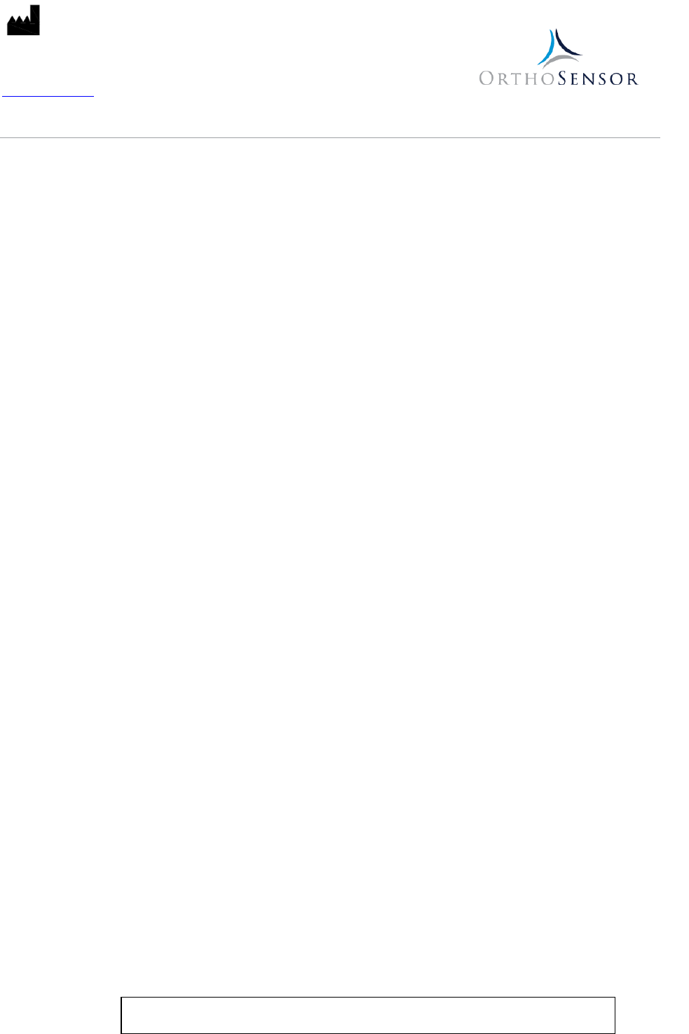
VERASENSE TROUBLESHOOTING
Table 1
Issue
Cause
Solution
VERASENSE device LED does not light up VERASENSE device batteries are dead
Discard VERASENSE device and
replace
VERASENSE Device not transmitting data
to LinkStation MINI or LinkStation MINI
Evaluation Kit
VERASENSE device is out of wireless
range
Move LinkStation MINI or LinkStation
MINI Evaluation Kit closer to
VERASENSE device
Move LinkStation MINI or LinkStation
MINI Evaluation Kit to achieve an
unobstructed line-of-sight to the
VERASENSE device field of use
VERASENSE device is powered off
Activate with LinkStation MINI or
LinkStation MINI Evaluation Kit
magnet
VERASENSE device batteries are low
Discard VERASENSE device and
replace
VERASENSE device breakage VERASENSE device applied load is
beyond limit
VERASENSE device internal
components are non-sterile and non-
medical grade. Ensure patient safety.
Discard device and replace.
Lag in reported data Software latency
Maintain knee position until data
settles (approximately 5 seconds)
Note: Should any of the issues above arise please contact OrthoSensor Customer service at + 1 954-577-7770 for return or
replacement assistance.
DECONTAMINATION OF PRODUCT RETURNED FOR COMPLAINT INVESTIGATION
This section applies to all VERASENSE devices intended to be returned for complaint investigations. Any device that has been
opened/removed from sterile packaging and exposed to biohazardous material must be sent to central processing within the
hospital for decontamination according to this procedure prior to transport to OrthoSensor. The following guidelines have been
proven effective for cleaning VERASENSE devices but are not guaranteed to result in a safe handling environment or sterilized
devices.
Note: Should a device be clearly marked as having been used on a patient with HIV or infectious disease of equivalent
risk, the device must not be decontaminated but rather documented and destroyed.
Decontamination Procedure:
1. Create cleaning solution in labeled cleaning container by combining 2 ounces (59 mL) of ENZOL Enzymatic detergent
(or equivalent*) per gallon (3.8 L) of warm water.
2. Soak device(s) for 5 minutes. If necessary, use brush to clean any dried-on material.
3. Thoroughly rinse device(s) with clean running water. Dry device(s) and place on clean absorbent pad.
4. Fill labeled disinfection container with enough Cidex OPA solution (or equivalent*) to cover device(s) completely.
5. Immerse device(s) in solution and soak for 15 minutes. Ensure that all devices are 100% covered by the solution.
6. Remove device(s) and rinse for at least one minute with a large volume of clean water. Dry device(s) and place
decontaminated parts on clean absorbent pad.
*If equivalent agent is used, it is recommended to follow manufacturer’s instructions for creating cleaning and
disinfectant solutions. Once this procedure has been carried out, devices may be packaged in the enclosed return
envelope and transported per instructions on return envelope.
OrthoSensor, Inc.
1855 Griffin Road
Suite A-310
Dania Beach, FL 33004-2200 USA
www.orthosensor.com
LB-5135 Rev. 1 (EN) 5
06-2018
For further information, contact the OrthoSensor Customer Service Center by phone at + 1 954-577-7770 or by e-mail
at customerservice@orthosensor.com or go to www.orthosensor.com.
VERASENSE DEVICE SPECIFICATIONS
This device complies with Part 15 of the FCC Rules. Operation is subject to the following two conditions: (1) this device may not
cause harmful interference, and (2) this device must accept any interference received, including interference that may cause
undesired operation.
The VERASENSE for Biomet Vanguard, Stryker Triathlon, Zimmer NexGen, Smith & Nephew Legion, and Smith & Nephew Journey
II comply with Part 95 of the FCC rules. These devices may not interfere with stations operating in the 400.150–406.000 MHz
band in the Meteorological Aids, Meteorological Satellite, and Earth Exploration Satellite Services and must accept any
interference received, including interference that may cause undesired operation.
The VERASENSE for Zimmer Biomet Persona complies with Part 95 of the FCC rules. This device does not interfere with stations
operating in the 2402-2480 MHz band in the Meteorological Aids, Meteorological Satellite, and Earth Exploration Satellite Services
and must accept any interference received, including interference that may cause undesired operation.
Modification of this device may void the user’s authority to operate the equipment under the FCC rules above.
This equipment has been tested and found to comply with IEC 60601-1 - Medical electrical equipment - Part 1: General
requirements for basic safety and essential performance.
This equipment has been tested and found to comply with the EMC limits for the Medical Device Directive 93/42/EEC (EN 60601-
1-2). No essential performance was identified and tested. These limits are designed to provide reasonable protection against
harmful interference in a typical medical installation. This equipment generates and uses radio frequency energy and, if not
installed and used in accordance with the instructions, may cause harmful interference to other devices in the vicinity. However,
there is no guarantee that interference will not occur in a particular installation. If this equipment does cause harmful
interference with other devices, which can be determined by turning the equipment off and on, the user is encouraged to try to
correct the interference by one or more of the following measures:
- Reorient or relocate the receiving device
- Increase the separation between the equipment.
- Connect the equipment into an outlet on a circuit different from that to which the other device(s) is connected
- Consult OrthoSensor for help.
For additional safety information, see Table 4 – Table 7 in the attachments section, which document the intended use
environment and EMC compliance levels of VERASENSE.
VERASENSE is intended for use in the electromagnetic environment specified in this IFU.
ADDITIONAL WARNINGS
• Only use the accessories supplied with the VERASENSE. This includes the USB cable, power cord, mounting fixtures, etc.
• Do not power the transceiver from any device other than the provided LinkStation MINI or LinkStation MINI Evaluation Kit.
• Do not connect any other devices to the display unit input/output ports other than those supplied with the VERASENSE.
• WARNING: No modification of this equipment is allowed.
• Modification is only allowed by the manufacturer of this equipment
• Transceiver cleaning and disinfection instructions: wipe transceiver down with 70% isopropyl alcohol wipes after each use
OrthoSensor, Inc.
1855 Griffin Road
Suite A-310
Dania Beach, FL 33004-2200 USA
www.orthosensor.com
LB-5135 Rev. 1 (EN) 6
06-2018
For further information, contact the OrthoSensor Customer Service Center by phone at + 1 954-577-7770 or by e-mail
at customerservice@orthosensor.com or go to www.orthosensor.com.
IEC 60601-1 Medical Electrical Equipment Classification for Protection Against Electrical Shock
Sensor: Internally powered (3.1 V dc)
VERASENSE for Stryker Triathlon, Zimmer NexGen, Biomet Vanguard, Smith & Nephew Journey II, and Smith
& Nephew Legion Devices: Internally Powered by Energizer 362/361 battery
VERASENSE for Zimmer Biomet Persona Devices: Internally powered by Renata CR1216 MFR FH battery
LinkStation MINI / LinkStation MINI Evaluation Kit:
Transceiver: Class II USB powered and intended to be connected to the USB port of the LinkStation MINI
display unit (5 V dc)
Display Unit: Class III (65W universal 3-pin jack, 100-240V, 1.5A, 50-60Hz)
EQUIPMENT NOT SUITABLE FOR USE IN THE PRESENCE OF A FLAMMABLE ANAESTHETIC MIXTURE WITH AIR OR WITH OXYGEN OR
CONTINUOUS FLOW OF NITROUS OXIDE
CONTINUOUS OPERATION WITH SHORT-TIME LOADING
OrthoSensor, Inc.
1855 Griffin Road
Suite A-310
Dania Beach, FL 33004-2200 USA
www.orthosensor.com
LB-5135 Rev. 1 (EN) 7
06-2018
For further information, contact the OrthoSensor Customer Service Center by phone at + 1 954-577-7770 or by e-mail
at customerservice@orthosensor.com or go to www.orthosensor.com.
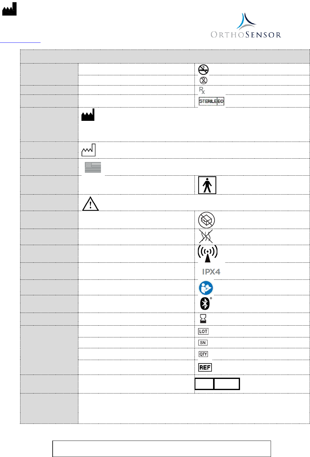
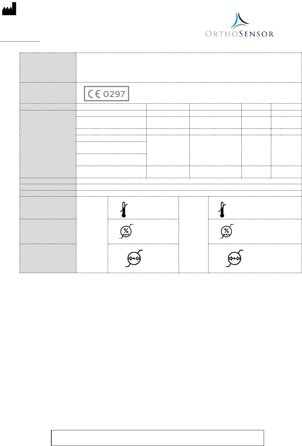
Table 2 – Symbols
Type:
Do not re-sterilize
Single Procedure use / Do not re-use
Prescription:
By Prescription Only
Sterility: Sterilized using ethylene oxide
Manufacturer:
OrthoSensor, Inc.
1855 Griffin Road
Suite A-310
Dania Beach, FL 33004-2200 USA
Date of Manufacture:
Made in USA
Device Type: Type BF (sensor only)
Caution:
Use: Do not use if package is damaged
Non-pyrogenic
Non-ionizing Radiation
Ingress Protection Rating
Consult User Guide
Bluetooth® Symbol
Shelf Life: Use-by date
Identification:
Batch Code
Serial number
Quantity
Catalog number
Authorized
Representative in the
European Community
Regulatory and Marketing Services-UK, LTD
28 Trinity Road,
Nailsea, Somerset BS48 4NU United Kingdom
Australia Sponsor
PharmaDev Consulting Pty Ltd.
Level 12
95 Pitt Street
Sydney NSW 2000
Australia
EC
REP
OrthoSensor, Inc.
1855 Griffin Road
Suite A-310
Dania Beach, FL 33004-2200 USA
www.orthosensor.com
LB-5135 Rev. 1 (EN) 8
06-2018
For further information, contact the OrthoSensor Customer Service Center by phone at + 1 954-577-7770 or by e-mail
at customerservice@orthosensor.com or go to www.orthosensor.com.
New Zealand Sponsor
PharmaDev Consulting Pty Ltd.
Level 10
21 Queen Street
Auckland 1010
New Zealand
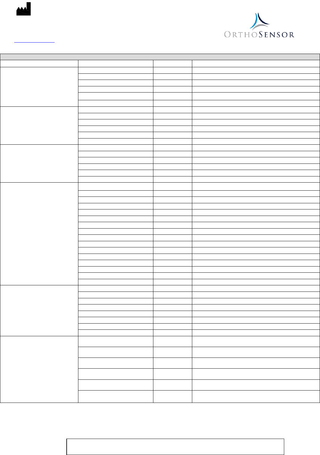
CE Mark and Notified
Body Number
Model
FCC ID
Frequency band
Modulation
EIRP
FCC ID:
VERASENSE for Stryker Triathlon
XNL-ORTHOSNSR1
402.0 - 405.0 MHz
GFSK
1.83 nW
VERASENSE for Biomet
Vanguard
XNL-ORTHOSNSR2 404.3 - 404.3 MHz GFSK 3.314 nW
Transceiver
XNL-ORTHOSNSR3
401.05 - 405.55 MHz
GFSK
N/A
VERASENSE for Zimmer NexGen
XNL-ORTHOSNSR5 404.3 - 404.3 MHz GFSK 1.31 µW
VERASENSE for Smith &
Nephew Journey II
VERASENSE for Smith &
Nephew Legion
VERASENSE for Zimmer Biomet
Persona
XNL-ORTHOSNSR7 2402 - 2480 MHz GFSK 1.26mW
Operating Range:
6.5 ft [2m] Unobstructed
Power Supply:
Internally powered at less than 3.3 VDC
Battery Life:
40 minutes (approximate)
Temperature Limit:
Operation
37°C
15°C
Storage
50°C
0°C
Relative Humidity:
100%, submersion
30%
80%, non-condensing
10%
Atmospheric Pressure:
106 kPa
47 kPa
106 kPa
36 kPa
OrthoSensor, Inc.
1855 Griffin Road
Suite A-310
Dania Beach, FL 33004-2200 USA
www.orthosensor.com
LB-5135 Rev. 1 (EN) 9
06-2018
For further information, contact the OrthoSensor Customer Service Center by phone at + 1 954-577-7770 or by e-mail
at customerservice@orthosensor.com or go to www.orthosensor.com.
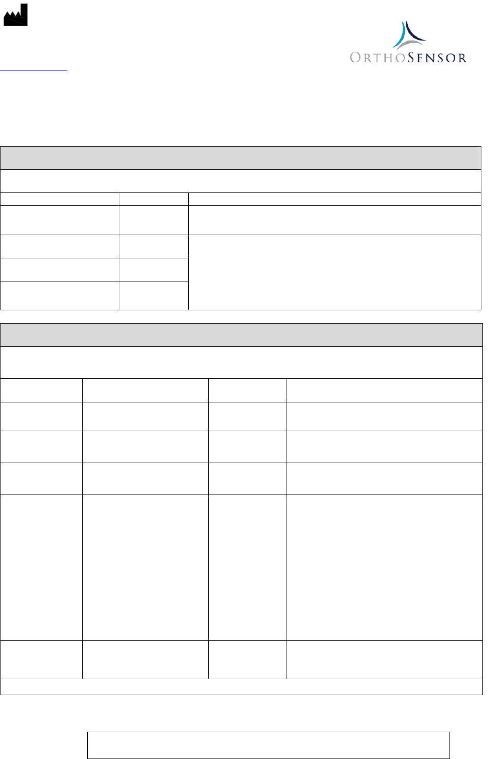
Table 3 – Catalog Numbers
VERASENSE Device Model
VERASENSE Catalog Number
Size
Compatible Implant System Catalog Number
VERASENSE for Biomet Vanguard
BMT-VGCR 63
63/67
32-483720, 32-483722, 32-483724, 32-483726, 32-483728
BMT-VGCR 71
71/75
32-483740, 32-483742, 32-483744, 32-483746, 32-483748
BMT-VGCR 79
79/83
32-483760, 32-483762, 32-483764, 32-483766, 32-483768
BMT-VGPS 63
63/67
32-483820, 32-483822, 32-483824, 32-483826, 32-483828
BMT-VGPS 71
71/75
32-483840, 32-483842, 32-483844, 32-483846, 32-483848
BMT-VGPS 79
79/83
32-483860, 32-483862, 32-483864, 32-483866, 32-483868
VERASENSE for Stryker Triathlon
SYK-TRCR 02
2
5530-T-209, 5530-T-211, 5530-T-213, 5530-T-216
SYK-TRCR 03
3
5530-T-309, 5530-T-311, 5530-T-313, 5530-T-316
SYK-TRCR 04
4
5530-T-409, 5530-T-411, 5530-T-413, 5530-T-416
SYK-TRCR 05
5
5530-T-509, 5530-T-511, 5530-T-513, 5530-T-516
SYK-TRCR 06
6
5530-T-609, 5530-T-611, 5530-T-613, 5530-T-616
SYK-TRCR 07
7
5530-T-709, 5530-T-711, 5530-T-713, 5530-T-716
VERASENSE for Zimmer NexGen
ZMR-NGCRCH34
C-H/3-4
00-5971-030-10, 00-5971-030-12, 00-5971-030-14, 00-5971-030-17
ZMR-NGCRCH56
C-H/5-6
00-5971-040-10, 00-5971-040-12, 00-5971-040-14, 00-5971-040-17
ZMR-NGCRCH70
C-H/7-10
00-5971-050-10, 00-5971-050-12, 00-5971-050-14, 00-5971-050-17
ZMR-NGPSCD34
C-D/3-4
00-5961-030-10, 00-5961-030-12, 00-5961-030-14, 00-5961-030-17
ZMR-NGPSEF34
E-F/3-4
00-5961-032-10, 00-5961-032-12, 00-5961-032-14, 00-5961-032-17
ZMR-NGPSEF56
E-F/5-6
00-5961-040-10, 00-5961-040-12, 00-5961-040-14, 00-5961-040-17
VERASENSE for Smith & Nephew
Journey II
SNN-JRNYBCS12-L
1-2 Left
74027221, 74027222, 74027223, 74027224, 74027225
SNN-JRNYBCS12-R
1-2 Right
74027211, 74027212, 74027213, 74027214, 74027215
SNN-JRNYBCS34-L
3-4 Left
74027241, 74027242, 74027243, 74027244, 74027245
SNN-JRNYBCS34-R
3-4 Right
74027231, 74027232, 74027233, 74027234, 74027235
SNN-JRNYBCS56-L
5-6 Left
74027261, 74027262, 74027263, 74027264, 74027265
SNN-JRNYBCS56-R
5-6 Right
74027251, 74027252, 74027253, 74027254, 74027255
SNN-JRNYBCS78-L
7-8 Left
74027281, 74027282, 74027283, 74027284, 74027285
SNN-JRNYBCS78-R
7-8 Right
74027271, 74027272, 74027273, 74027274, 74027275
SNN-JRNYCR12-L
1-2 Left
74025621, 74025622, 74025623, 74025624, 74025625
SNN-JRNYCR12-R
1-2 Right
74025611, 74025612, 74025613, 74025614, 74025615
SNN-JRNYCR34-L
3-4 Left
74025641, 74025642, 74025643, 74025644, 74025645
SNN-JRNYCR34-R
3-4 Right
74025631, 74025632, 74025633, 74025634, 74025635
SNN-JRNYCR56-L
5-6 Left
74025661, 74025662, 74025663, 74025664, 74025665
SNN-JRNYCR56-R
5-6 Right
74025651, 74025652, 74025653, 74025654, 74025655
SNN-JRNYCR78-L
7-8 Left
74025681, 74025682, 74025683, 74025684, 74025685
SNN-JRNYCR78-R
7-8 Right
74025671, 74025672, 74025673, 74025674, 74025675
VERASENSE for Smith & Nephew
Legion
SNN-LGNPS12
1-2
71453201, 71453171, 71453202, 71453172, 71453203
SNN-LGNPS34
3-4
71453211, 71453173, 71453212, 71453174, 71453213
SNN-LGNPS56
5-6
71453221, 71453175, 71453222, 71453176, 71453223
SNN-LGNPS78
7-8
71453231, 71453177, 71453232, 71453178, 71453233
SNN-LGNCR12
1-2
71453101, 71453181, 71453102, 71453182, 71453103
SNN-LGNCR34
3-4
71453111, 71453183, 71453112, 71453184, 71453113
SNN-LGNCR56
5-6
71453121, 71453185, 71453122, 71453186, 71453123
SNN-LGNCR78
7-8
71453131, 71453187, 71453132, 71453188, 71453133
VERASENSE for Zimmer Biomet
Persona ZBH-PSNCRCD39-L C-D/3-9 Left
42-5170-004-10, 42-5170-003-03, 42-5170-003-13, 42-5279-003-00,
42-5279-003-01, 42-5279-003-02, 42-5279-003-03, 42-5279-003-04
ZBH-PSNCRCD39-R C-D/3-9 Right
42-5270-004-10, 42-5270-003-03, 42-5270-003-13, 42-5279-003-00,
42-5279-003-01, 42-5279-003-02, 42-5279-003-03, 42-5279-003-04
ZBH-PSNCREF311-L E-F/3-11 Left
42-5170-005-10, 42-5170-005-05, 42-5170-005-15, 42-5279-005-00,
42-5279-005-01, 42-5279-005-02, 42-5279-005-03, 42-5279-005-04
ZBH-PSNCREF311-R E-F/ 3-11 Right
42-5270-005-10, 42-5270-005-05, 42-5270-005-15, 42-5279-005-00,
42-5279-005-01, 42-5279-005-02, 42-5279-005-03, 42-5279-005-04
ZBH-PSNCRGH712-L G-H/7-12 Left
42-5170-006-10, 42-5170-007-07, 42-5170-007-17, 42-5279-007-00,
42-5279-007-01, 42-5279-007-02, 42-5279-007-03, 42-5279-007-04
ZBH-PSNCRGH712-R G-H/7-12 Right
42-5270-006-10, 42-5270-007-07, 42-5270-007-17, 42-5279-007-00,
42-5279-007-01, 42-5279-007-02, 42-5279-007-03, 42-5279-007-04
OrthoSensor, Inc.
1855 Griffin Road
Suite A-310
Dania Beach, FL 33004-2200 USA
www.orthosensor.com
LB-5135 Rev. 1 (EN) 10
06-2018
For further information, contact the OrthoSensor Customer Service Center by phone at + 1 954-577-7770 or by e-mail
at customerservice@orthosensor.com or go to www.orthosensor.com.
Attachments:
• Guidance and Manufacturer’s Declaration - Electromagnetic Compatibility (EMC): The VERASENSE device and
accessories have been tested and found to comply with the electromagnetic compatibility (EMC) limits for medical
devices to IEC 60601-1-2:2007. Refer to the tables below.
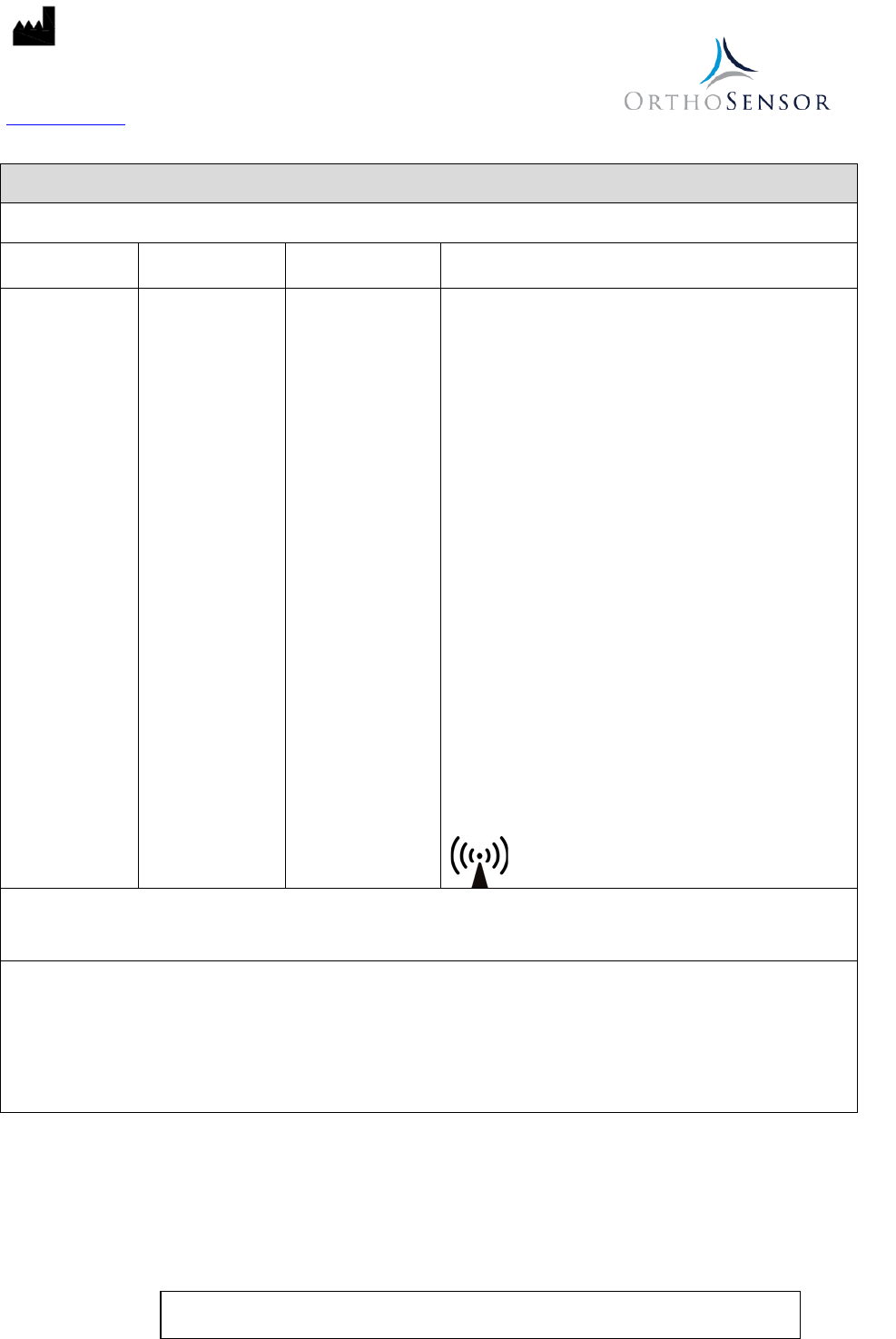
Table 4 - Guidance and manufacturer’s declaration – electromagnetic emissions
The VERASENSE is intended for use in the electromagnetic environment specified below. The customer or the user of the
VERASENSE should assure that it is used in such an environment.
Emissions Test
Compliance
Electromagnetic Environment – Guidance
RF Emissions
CISPR 11
Group 1
The VERASENSE uses RF energy only for its internal function. Therefore, its
RF emissions are very low and are not likely to cause any interference in
nearby electronic equipment.
RF Emissions
CISPR 11
Class A
The VERASENSE is suitable for use in all establishments other than domestic
and those directly connected to the public low-voltage power supply network
that supplies buildings used for domestic purposes.
Harmonic Emissions
IEC 61000-3-2
Not applicable
Voltage Fluctuations/Flicker
Emissions
IEC 61000-3-3
Not applicable
Table 5 - Guidance and Manufacturer’s Declaration – Electromagnetic Emissions
The VERASENSE are intended for use in the electromagnetic environment specified below.
The customer or the user of the VERASENSE should assure that it is used in such an environment.
Immunity Test
IEC 60601
Test level
Compliance
Level Electromagnetic Environment – Guidance
Electrostatic
discharge (ESD)
IEC 61000-4-2
± 6 kV contact
± 8 kV air
± 6 kV contact
± 8 kV air
Floors should be wood, concrete or ceramic tile. If
floors are covered with synthetic material, the
relative humidity should be at least 30%
Electrical fast
transient/burst
IEC 61000-4-4
± 2 kV for power supply lines
± 1 kV for input/output lines
Not applicable
Mains power quality should be that of a typical
commercial or hospital environment.
Surge
IEC 61000-4-5 ± 1 kV line(s) to line(s)
± 2 kV line(s) to earth
Not applicable
Mains power quality should be that of a typical
commercial or hospital environment.
Voltage dips, short
interruptions and
voltage variations
on power supply
input lines
IEC 61000-4-11
<5 % UT
(>95% dip in UT)
for 0,5 cycle
40% UT
(60% dip in UT)
for 5 cycles
70% UT
(30% dip in UT)
for 25 cycles
<5% UT
(>95% dip in UT)
for 5 s
Not applicable
Mains power quality should be that of a typical
commercial or hospital environment. If the user of
the VERASENSE
requires continued operation
during power mains interruptions, it is
recommended that the VERASENSE be powered
from an uninterruptible power supply or a battery.
Power Frequency
(50/60 Hz)
Magnetic Field
IEC 61000-4-8
3 A/m
3 A/m
Power frequency magnetic fields should be at
levels characteristic of a typical location in a typical
commercial or hospital environment.
NOTE: U
T
is the a.c. mains voltage prior to application of the test level.
OrthoSensor, Inc.
1855 Griffin Road
Suite A-310
Dania Beach, FL 33004-2200 USA
www.orthosensor.com
LB-5135 Rev. 1 (EN) 11
06-2018
For further information, contact the OrthoSensor Customer Service Center by phone at + 1 954-577-7770 or by e-mail
at customerservice@orthosensor.com or go to www.orthosensor.com.
Table 6 - Guidance and manufacturer’s declaration – electromagnetic immunity
The VERASENSE is intended for use in the electromagnetic environment specified below.
The customer or the user of the VERASENSE should assure that it is used in such an environment.
Immunity test
IEC 60601
Test Level
Compliance
Level
Electromagnetic environment – guidance
Conducted RF
IEC 61000-4-6
Radiated RF
IEC 61000-4-3
3 Vrms
150 kHz to 80 MHz
3 V/m
80 MHz to 2.5 GHz
Not applicable
3 V/m
80 MHz to 2.5 GHz
Portable and mobile RF communications equipment should
be used no closer to any part of the VERASENSE and
accessories, including cables, than the recommended
separation distance calculated from the equation applicable
to the frequency of the transmitter.
Recommended separation distance
Not applicable
d = 1.2 √P 80 MHz to 800 MHz
d = 2.3 √P 800 MHz to 2.5 GHz
Where p is the maximum output power rating of the
transmitter in watts (W) according to the transmitter
manufacturer and d is the recommended separation distance
in meters (m).
Field strengths from fixed RF transmitters, as determined by
an electromagnetic site survey,a should be less than the
compliance level in each frequency range.b
Interference may occur in the vicinity of equipment marked
with the following symbol:
NOTE 1 At 80 MHz and 800 MHz, the higher frequency range applies.
NOTE 2 These guidelines may not apply in all situations. Electromagnetic propagation is affected by absorption and reflection
from structures, objects and people.
a Field strengths from fixed transmitter, such as base stations for radio (cellular/cordless) telephones and land mobile radios,
amateur radio, AM and FM radio broadcast cannot be predicted theoretically with accuracy. To assess the electromagnetic
environment due to fixed RF transmitters, an electromagnetic site survey should be considered. If the measured field
strength in the location in which the VERASENSE is used exceeds the applicable RF compliance level above, the
VERASENSE should be observed to verify normal operation. If abnormal performance is observed, additional measures may
be necessary, such as re-orienting or relocating the VERASENSE.
b Over the frequency range 150 kHz to 80 MHz, field strengths should be less than not applicable.
OrthoSensor, Inc.
1855 Griffin Road
Suite A-310
Dania Beach, FL 33004-2200 USA
www.orthosensor.com
LB-5135 Rev. 1 (EN) 12
06-2018
For further information, contact the OrthoSensor Customer Service Center by phone at + 1 954-577-7770 or by e-mail
at customerservice@orthosensor.com or go to www.orthosensor.com.
Table 7 - Recommended separation distances between portable and mobile RF communications equipment and the
VERASENSE
The VERASENSE is intended for use in an electromagnetic environment in which RF disturbances are controlled. The customer
or the user of the VERASENSE can help prevent electromagnetic interference by maintaining a minimum distance between
portable and mobile RF communications equipment (transmitters) and VERASENSE as recommended below, according to the
maximum output power of the communications equipment.
Rated maximum
output power of
transmitter
W
Separation distance according to frequency of transmitter
m
150 kHz to 80 MHz
d = [3.5 / V1] √P
80 MHz to 800 MHz
d = 1.2 √P
800 MHz to 2.5 GHz
d = 2.3 √P
0.01 Not applicable 0.12 0.23
0.1 Not applicable 0.38 0.73
1 Not applicable 1.2 2.3
10 Not applicable 3.8 7.3
100 Not applicable 12 23
For transmitters rated at a maximum output power not listed above, the recommended separation distance d in meters (m) can
be determined using the equation applicable to the frequency of the transmitter, where P is the maximum output power rating of
the transmitter in watts (W) according to the transmitter manufacturer.
NOTE 1 - At 80 MHz and 800 MHz, the separation distance for the higher frequency range applies.
NOTE 2 – These guidelines may not apply in all situations. Electromagnetic propagation is affected by absorption and reflection
from structures, objects and people.
