User Information for the TR100

Model Description Price(1-9)
EK100 ................Eval. Kit Set (2ea. TR100) for 3.3V, TTL/Cmos & OOK ........... $135
EK101 .................... Eval. Kit Set (2ea TR101) for 5V,TTL/Cmos & OOK ...........$150
*Kits Include: Instructions & Typical µC Interface
List Prices: TR100...$65 TR101...$70
1000 Pc. TR100 $24.95 TR101 $29
’s new TR100
is designed specifically for OEMs
to embed it in their systems & give
them competitive advantage in the
Wireless Market. The TR100 is very
economical and effective in
transceiving streams of data at high
rates over a short distance with mini-
mum power consumption lending it-
self to battery operated products.
The Licenseless ISM Band (FCC
Part 15) , low power & cost lends
the TR100 to many OEM products
for Telemetry, SCADA, DCS, Se-
curity, Transportation, Process Con-
trol, Agriculture, Pharmaceutical,
Paper and Pulp, Chemical and many
more (not authorized for life support
products). Note: Changing the an-
tenna on the TR100 will require FCC
(or your country’s) approval of the
system before you can offer it for
sale. See FCC CFR47, Parts 2 &
15.249). OTEK will supply you with
a copy of its own FCC Approval File
# for your reference. The TR100 is
available in kits or individual boards
(also see the TR200) with serial
RS232/485/TTL I/O or the TR300
“Plug-N-Play” version housed in a
“DB9” style case, ready to plug to
your PC. The TR200, TR300 and
TR400 include the PCs’ software
at no charge.
Operating Frequency ... 916.5MHz ±200KHz
Modulation ........................................... OOK
Data Rate ............................... OOK:19.2KB
Sleep Current ....................................... 25µA
Receive Current.................................... 6mA
Transmit Current ................................. 12mA
Peak Transmit Power ......................0.85mW
Indoor/Outdoor Range ................. 100/300FT
Voltage Input .................. 2.7-3.5 or 3.5-5.5V
.................................. 10mVrms Max. Ripple
Receiver’s Gain ............................... 100dBm
Size............ 0.15x0.85x1.85” (3.8x21.6x47m)
Operating Temperature ............. -20 to =75ºC
*Specifications & Prices Subject to
Change Without Notice.
SPECIFICATIONS @25ºC:
OTEK offers several kits at a reasonable price for your evaluation and
test of your application. The EK100 consists of 2 each TR100 ready for
you to apply power (3.3V) & signal from your own microprocessor or TTL
Signal. The EK101 is for 5VDC power.
Above kits accept TTL/CMOS I/O.
EVALUATION KITS:
If you want to bypass the in-
terface development, see
the TR200 data sheet for
models with serial I/O with
RS-232C/485 or TTL
ASCII either 5VDC or 8-
25VDC power input and
either PC pins or DB9 con-
nector in the same small
(1.85x0.85”x0.4”) package
(plus DB9); or the TR300
housed in a “DB9” plastic
housing only 1.7x3x.8”,
“Plug-N-Play” design.
Ready to plug in your PC’s
Serial Port.
ORDERING INFORMATION (1-00)
New!
LL
LL
Lowow
owow
ow C C
C C
Costost
ostost
ost
WIRELESSWIRELESS
WIRELESSWIRELESS
WIRELESS (R.F (R.F
(R.F (R.F
(R.F.) TRANSCEIVER TTL I/O MODULE.) TRANSCEIVER TTL I/O MODULE
.) TRANSCEIVER TTL I/O MODULE.) TRANSCEIVER TTL I/O MODULE
.) TRANSCEIVER TTL I/O MODULE
FOR FOR
FOR FOR
FOR OEMSOEMS
OEMSOEMS
OEMS
*916.5Mhz *19.2K Baud *Licenseless Band
ACTUAL SIZE
IF YOU
DON’T SEE
IT, ASK
FOR IT!
4016 E. TENNESSEE ST.
TUCSON, AZ. 85714 U.S.A.
Tel: 520-748-7900 Fax: 520-790-2808
Toll Free: 877-BAR-OTEK (227-6835)
E-Mail:sales@otekcorp.com
Web:www.otekcorp.com Since 1974
Model
TR100
R.F.
XCVR
Fax-Back:
520-748-1539-8710
Visa & Master Cards Accepted
J1 J2
Per Set

Operating Instructions for:
TR100, EK100
4016 E.Tennessee St., Tucson, AZ. 85714 USA
Toll Free: 1-877-BAR-OTEK (227-6835)
Tel: 520-748-7900 Fax: 520-790-2808
E-MAIL: sales@otekcorp.com
Web:http://www.otekcorp.com
A) Required Items:
1. 5VDC or 3.3VDC power supply with <10mVRMs noise
2. TTL pulse generators (one for data TX & one for PTT
pulse) >5MHz
B) Set Up & Test: (In A Hurry? Try #6)
Note:
1. The TR100 is available with 3.3 or 5VDC power input. Check your model before applying power and signal.
2. “PTT” (push to talk [transmit] timing is important, see Fig 1.
3. The PTT line should be always high (listening) except when ready to transmit and return high after end of transmission.
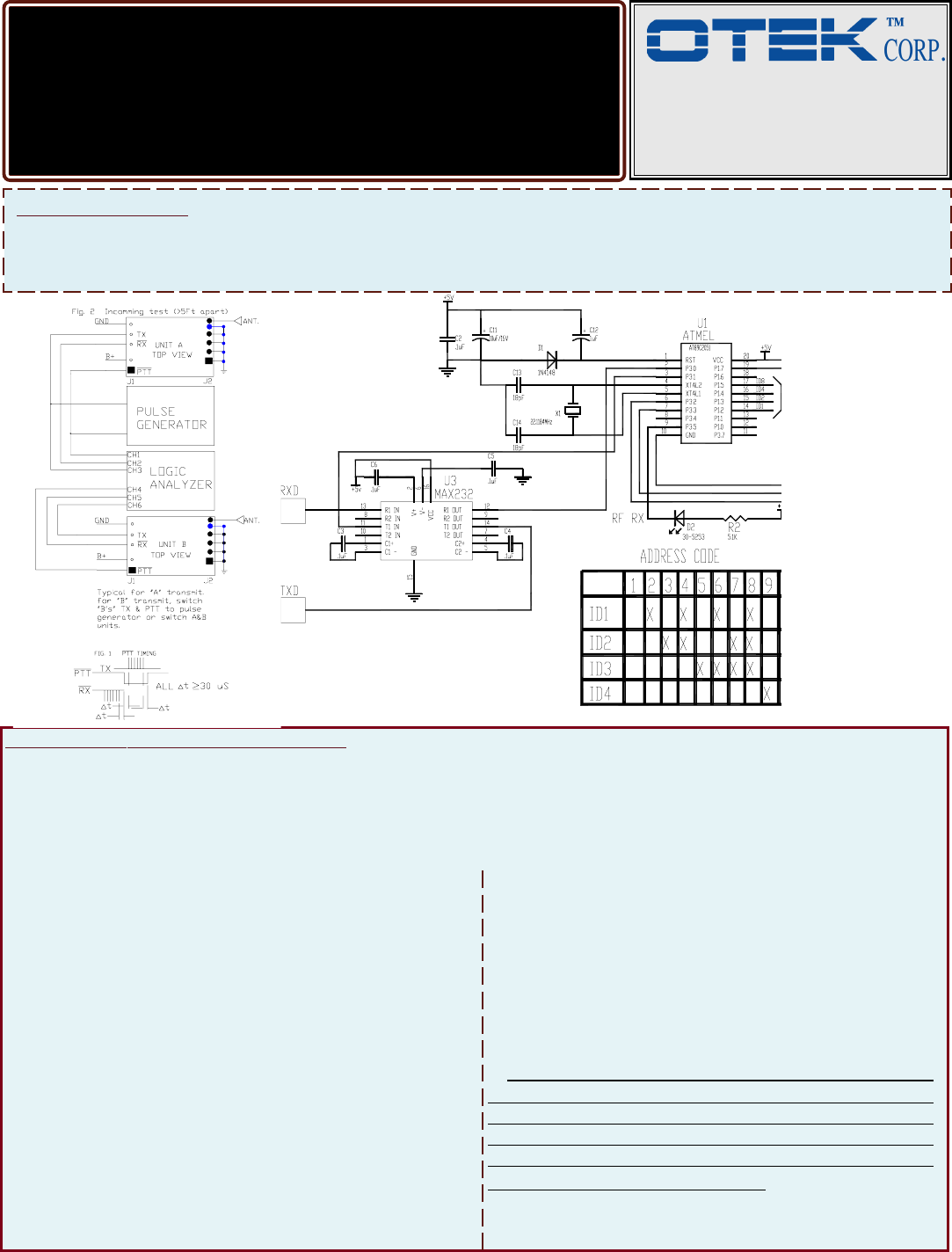
1. Solder the supplied antenna on the square Pad and
connect power and signal keeping the units 5+ feet
apart (see Fig2).
2. On unit “A” pulse PTT low (Pin 1) and apply 10 posi-
tive pulses (at 1KHz) to “TX” (Pin4), unit “B” should
output (negative) 10 negative pulses on its RX (Pin3).
3. Repeat 2 above but using unit “B” as the transmitter
and “A” as the receiver.
4. If 2 & 3 OK, move units farther apart and repeat; if
not, check your connections and scope time base. The
“TR100” will transmit at 916.5MHz @ 19.2K baud data
rate.
5. If #4 above is OK, incoming test is completed and
you are ready to customize the “TR100”. Fig.3 shows
the typical RS-232C to RF interface used on our own
“TR200” model. You are welcome to reproduce it
and develop your own software to satisfy your needs,
or buy the preprogrammed uC (Atmel P/N
AT89C2051) our p/n 29-2051P-TR200.0 for $25.00
ea. or buy the “TR200” (RF to RS232) transceiver or
license the source code for the uC for $250.00 one
time plus $1.00 per unit sold.
6. Simple Application & Test: Hz to Hz, Pulse to Pulse,
Event to Event, Etc. Simply ground PTT (Pin 1) apply
TTL Pulse(s) to TX (Pin 4) on “Transmitter”. Con-
nect PTT (Pin 1) to +5V and your counter or measur-
ing device to the RX (Pin 3) on the “Receiver” and
filter the 916.5MHz modulation..
Contact OTEK for further details at :
support@otekcorp.com. Attn: Legal Dept
3. Logic analyzer or storage oscilloscope
>50MHz
4. Two “TR100” Series Transceivers
5. Or Just Your TTL I/O Signals
If data is corrupted (RX), check your power supply
(battery pack is preferred for low noise and portabil-
ity) and pulse generator’s rise time (<50nS).
Fig. 3