Ott Hydromet Business Unit Adcon Telemetry A432 UHF radio module User Manual A432 Radio Module UM
Adcon Telemetry GmbH UHF radio module A432 Radio Module UM
Users/Integrators Manual

A432 Radio Module UM.docx Page 1 of 5
OTT Hydromet GmbH
Business Unit Adcon Telemetry
Inkustraße 24
3400 Klosterneuburg, Austria
Tel.: +43 2243/38280-58
Mob.: +43 664 85 474 55
Fax: +43 2243/38280-6
g.chvatal@ott.com
www.adcon.com
A432 RADIO MODULE
User Manual
Date: 2017/10/13
A432 Radio Module UM.docx Page 2 of 5
ABOUT THE A431 RADIO MODULE
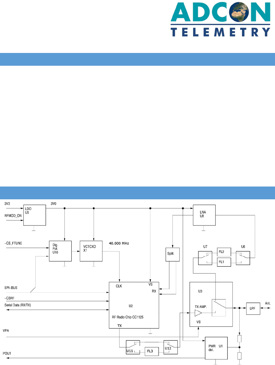
The A431 was specially designed for narrow-band FM data communication. The complete transceiver is
enclosed in a screening shield.
The radio module A432 mainly consists of:
• CC1125 Ultra High Performance RF Narrowband Transceiver (U2), Texas Instruments
• RF Front End Module RF6504 (TX amplifier and antenna switch) (U3), RFMD
• Low Noise, Low Current Amplifier (LNA)(U8), Skyworks
• LTC5507 RF Power Detector (U1), Linear Technology
• SAW RX Filter (FL1, FL2)(for low and high band selection)
• SAW TX Filter for EN300 220 operation (FL3)
The module operates in the 430 to 470 MHz range, making it compatible with most radio communication
regulations in the world. The output power is 0.5 W, while the modulation is narrow-band FM (12.5, 20 or
25 kHz channel spacing). The power consumption in receive mode is remarkably low (under 42 mA).
BLOCK DIAGRAM
A432 Radio Module UM.docx Page 3 of 5
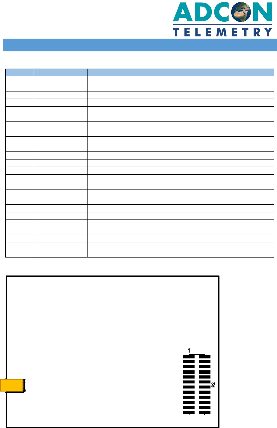
THE MODULE CONNECTOR
All control signals and supply voltages are accessible via the 24 pin connector P2.
PIN Name Function
1 VPA PA power supply, 3.6 V
2 VPA PA power supply, 3.6 V
3 VDD_IN Power supply, 3.0 V
4 RFMOD_ON RF module enable, HIGH = enable
5 SCLK SPI clock
6 SO SPI serial data output
7 SI SPI serial data input
8 -CSRF SPI chip select, LOW = selected
9 -CCRESET Reset signal for transceiver chip, LOW = reset
10 RXDATA Received data output
11 TXDATA Transmit data input
12 RXTXCLK Receive/transmit clock
13 RXEN Receiver enable
14 TXEN Transmitter enable
15 POUT Output power measurement
16 -FEEN Front end enable, LOW = enable
17 VCTCXO_ON VCTCXO enable input, HIGH = enable
18 LBS Low band select, 430 – 450 MHz
19 HBS High band select, 450 – 470 MHz
20 -CSFTUNE Chip select frequency fine tune
21 CFG0 HW configuration bit 0
22 CFG1 HW configuration bit 1
23 CFG2 HW configuration bit 2
24 GND Ground connection
3 additional GND connections are made by the module mounting holes.
Figure 1, Module Bottom Side
P1
A432 Radio Module UM.docx Page 4 of 5
THE ANTENNA CONNECTOR
The antenna is connected to the module via the MMCX connector P1.
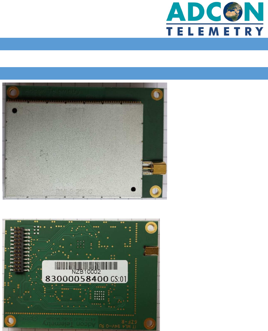
A432 MODULES’S PHOTOGRAPHS
Figure 2, A432 TOP VIEW, closed lid
Figure 3, A432 BOTTOM VIEW

A432 Radio Module UM.docx Page 5 of 5
FCC AND IC STATEMENT
FCC PART 15.21 STATEMENT
Changes or modifications not expressly approved by Ott Hydromet GmbH could void the user’s authority to
operate the equipment.
RSS-GEN, CNR-GEN 8.4
This device complies with Industry Canada’s licence-exempt RSSs. Operation is subject to the following two
conditions:
(1) This device may not cause interference; and
(2) This device must accept any interference, including interference that may cause undesired operation of the
device.
Le présent appareil est conforme aux CNR d’Industrie Canada applicables aux appareils radio exempts de
licence. L’exploitation est autorisée aux deux conditions suivantes :
(1) l’appareil ne doit pas produire de brouillage;
(2) l’utilisateur de l’appareil doit accepter tout brouillage radioélectrique subi, même si le brouillage est
susceptible d’en compromettre le fonctionnement.