Ott Hydromet Business Unit Adcon Telemetry A723-S4 Telemetry transceiver User Manual
Adcon Telemetry GmbH Telemetry transceiver
UserManual.wiki
>
Ott Hydromet Business Unit Adcon Telemetry
>
A723 S4 User Manual
User Manual
Navigation menu
Upload a User Manual
Namespaces
Wiki Guide
HTML
PDF
Info
Views
User Manual
Discussion / Help
Navigation


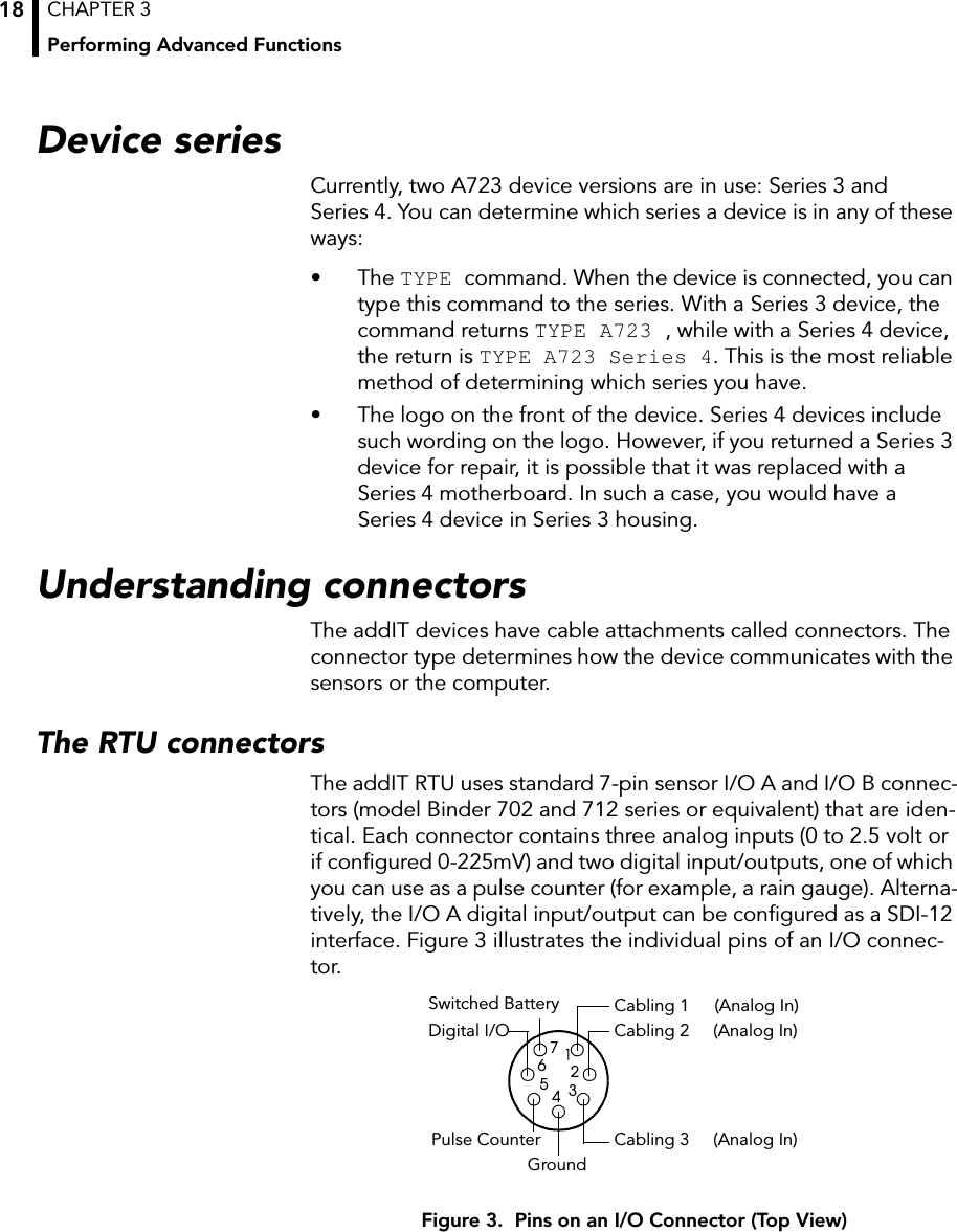
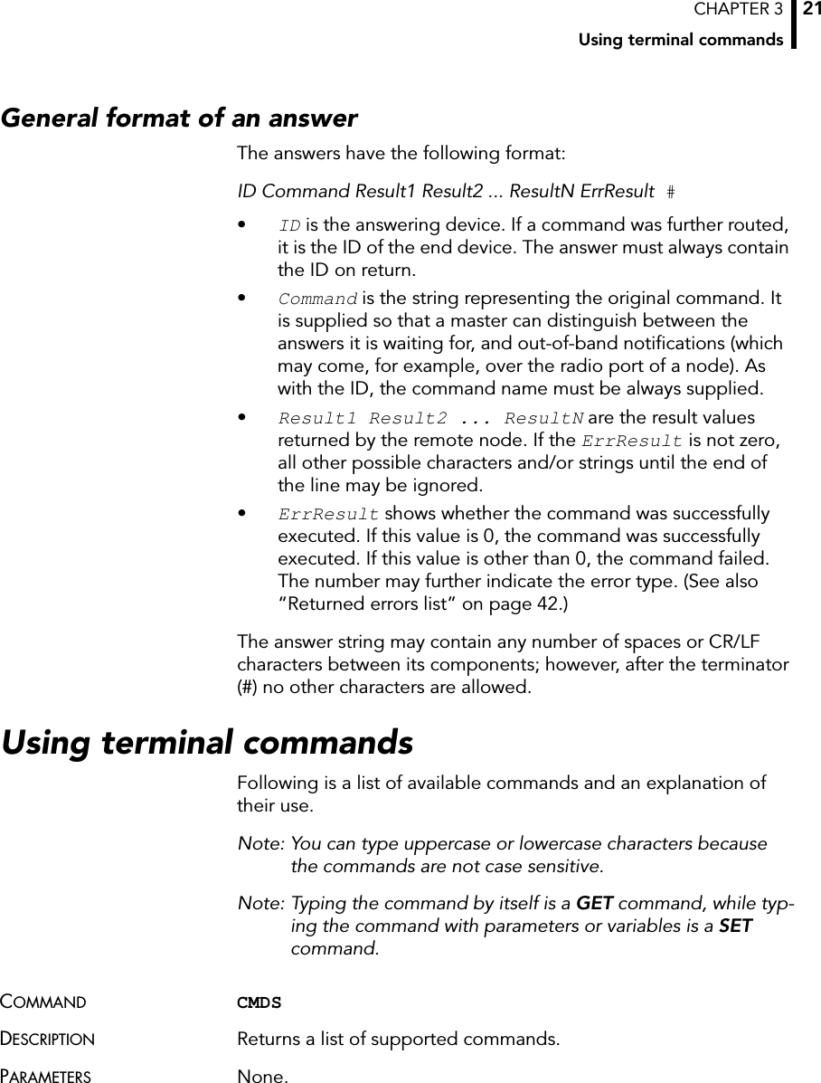
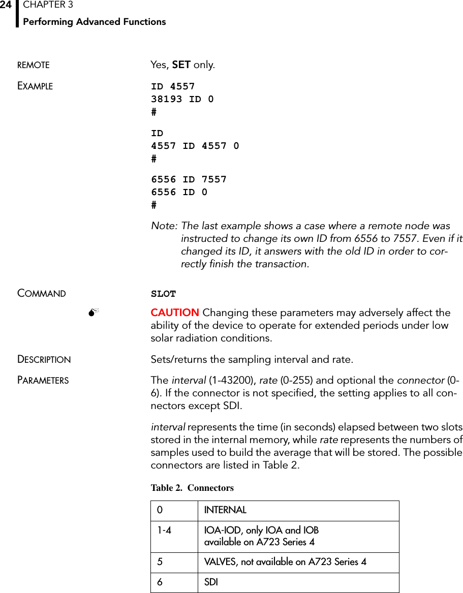
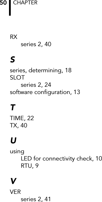
![CHAPTER 3Using terminal commands29The remote version is limited to a single frame. An example of such a command is given below:6367 DATA 6367 30/4/1999 14:50:00 6367 DATA 30 4 1999 14 54 55 14 38 255 255 77 0 0 89 156 126 20 0 0 0 0 3185 0 #Notice that if you need to get data that is not the last (newest) slot remotely from a device, the ID must be supplied twice. If you need to get the last slot stored, you can ignore the ID and the date/time parameters:8300 DATA 8300 DATA 13 5 1999 19 26 36 14 38 255 255 79 0 0 87 148 149 15 0 0 0 0 3138 0COMMAND FDEVDESCRIPTION Displays info about internal memory or formats the internal mem-ory (destroys all the data)PARAMETERS None (to query the current format) or the new EEPROM type and optional the number of index entries. To format the EEPROM with the currently set type, specify type 0.In GET mode, the following information is printed:current EEPROM type, the sizes of the two EEPROM chips, the range for index size, the total/used index entries, the total/used number of bytes for measurement data.Table 3. EEPROM TypesType Memory [kB] Min index entries Default index entries May index entries1 16 64 256 10242 16+16 128 512 20483 32 128 512 20484 16+32 192 768 3072](https://usermanual.wiki/Ott-Hydromet-Business-Unit-Adcon-Telemetry/A723-S4/User-Guide-948214-Page-29.png)
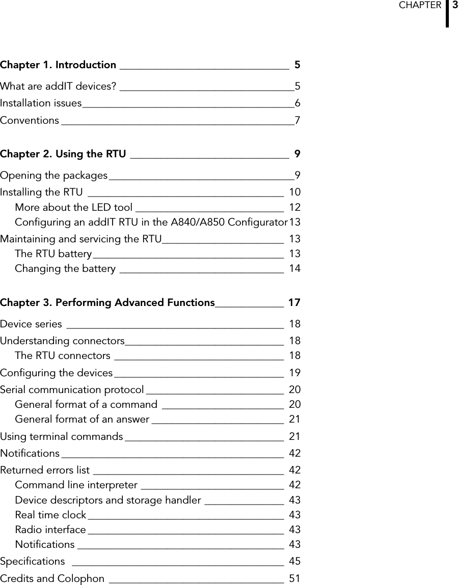
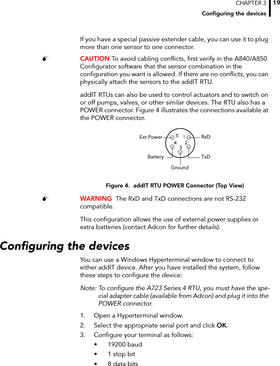
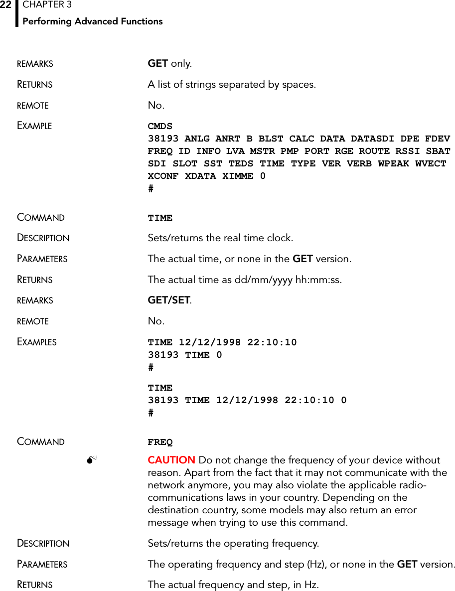
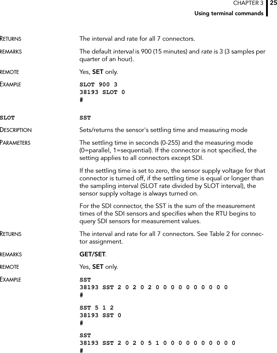
![CHAPTER 3Performing Advanced Functions30RETURNS The current setting.REMARKS Do not play with this settings, the correct setup depends on the memory components on the pcb and is a factory setup. Contact Adcon Telemetry for optimal index size setting.REMOTE Yes, SET only.EXAMPLE FDEV 38193 FDEV 1 16+0 64..1024 256/255 10240/10200 0 #FDEV 0 38193 FDEV 0 #Note: Depending on the device’s memory size, this command may take several seconds to complete.COMMAND INFODESCRIPTION Returns various status information.PARAMETERS None.5 32+16 192 768 30726 64 256 1024 40967 32+32 256 1024 40968 16+64 320 1280 51209 64+16 320 1280 512010 32+64 384 1536 614411 64+32 384 1536 614412 64+64 512 2048 8192Table 3. EEPROM TypesType Memory [kB] Min index entries Default index entries May index entries](https://usermanual.wiki/Ott-Hydromet-Business-Unit-Adcon-Telemetry/A723-S4/User-Guide-948214-Page-30.png)