Ott Hydromet Business Unit Adcon Telemetry A733GSM-GPRS Telemetry transceiver using GSM infrastructure User Manual 1
Adcon Telemetry GmbH Telemetry transceiver using GSM infrastructure 1
UserManual.wiki
>
Ott Hydromet Business Unit Adcon Telemetry
>
A733GSM GPRS User Manual
User Manual
Navigation menu
Upload a User Manual
Namespaces
Wiki Guide
HTML
PDF
Info
Views
User Manual
Discussion / Help
Navigation

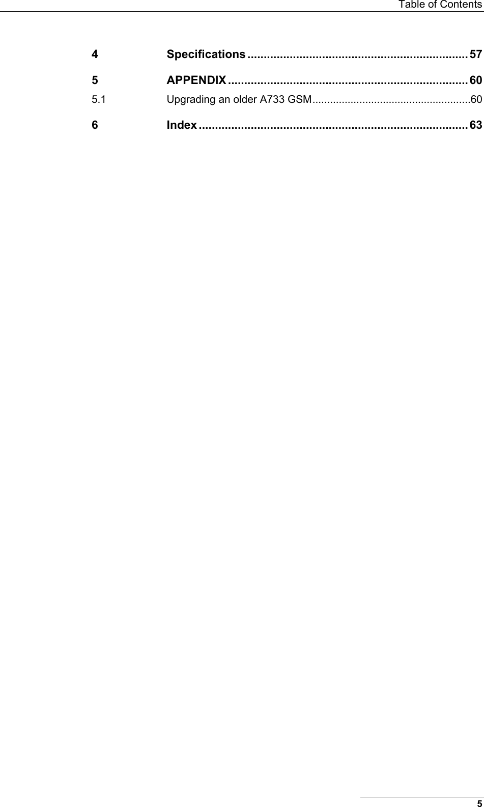
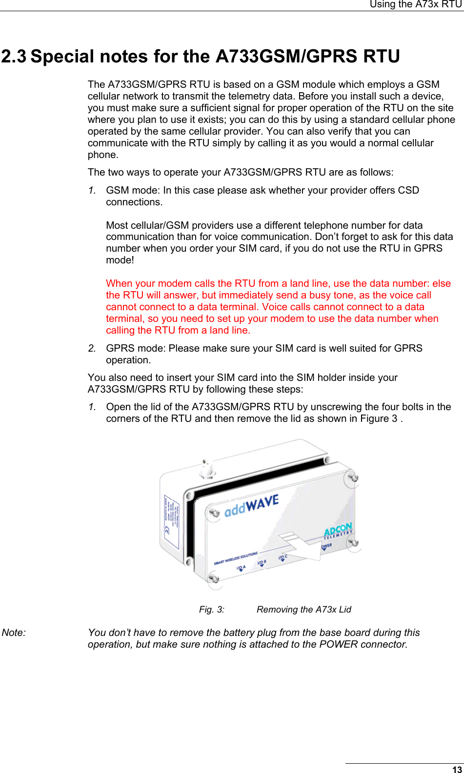
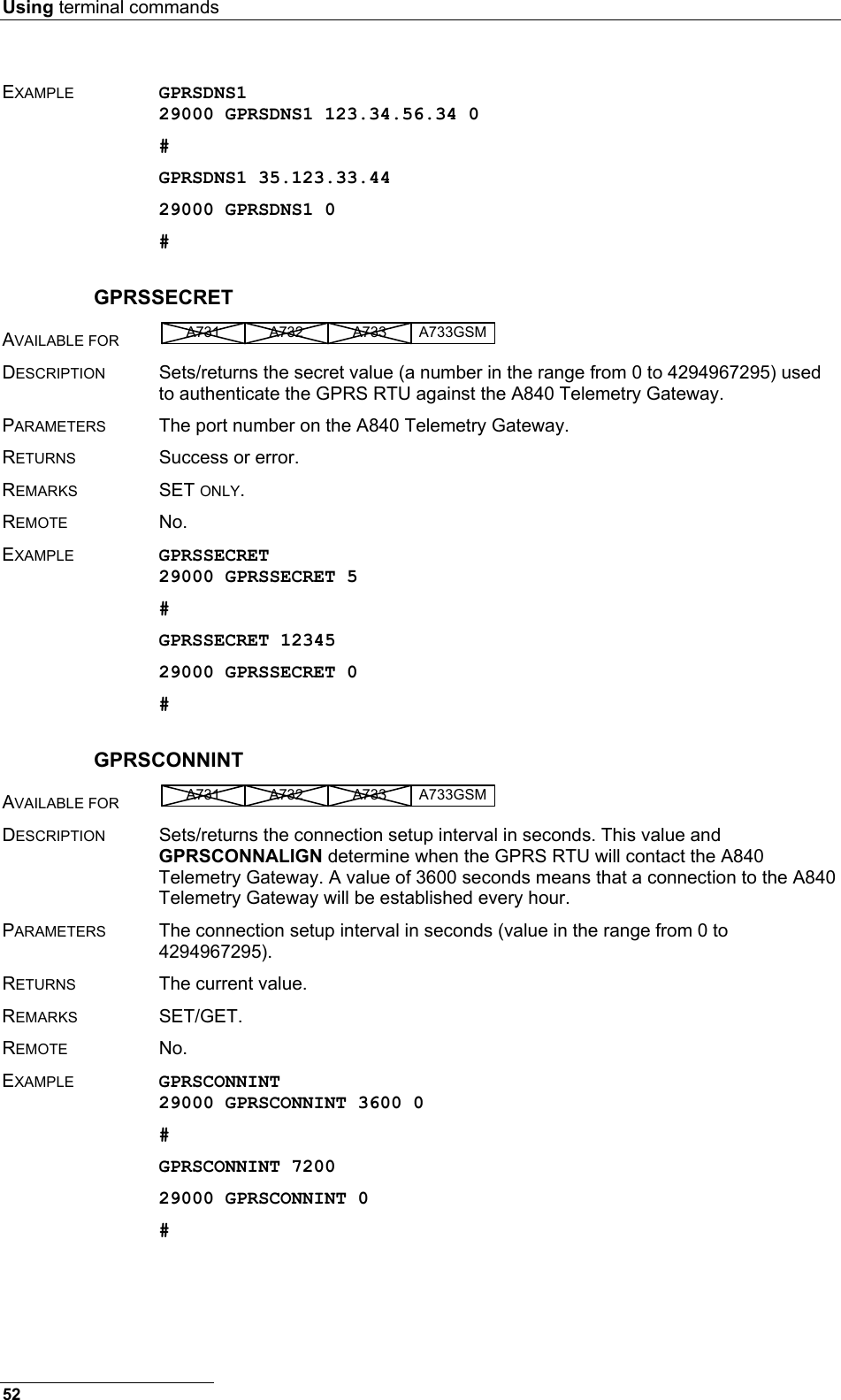
![Special notes for the A733GSM/GPRS RTU Set/configure the following parameters through a terminal connection to enable GPRS connection to your ISP: GPRSAPNSERV “[servername]” where [servername] is the name of the ISP's GPRS access server (required) GPRSAPNUN “[username]” where [username] is the name of the GPRS user’s name for the ISP (might be optional) GPRSAPNPW “[password]” where [password] is the password for the GPRS user (might be optional) The following examples show the GRPS parameters for an Austrian mobile phone services provider: GPRSAPNSERV “A1.net” GPRSAPNUN “ppp@A1plus.at” GPRSAPNPW “ppp” Note: Please take extreme care not to misspell the GPRS-parameter values, and not to switch the case of letters. Misspelled names/entries could cause the RTU not to connect to the GPRS network or A840. Configuring the TCP Parameters The A733 GSM/GPRS RTU will only connect to the A840 Telemetry Gateway if the following TCP Parameters are set: GPRSHOST “[a840-ipaddress]” where [a840-ipaddress] is the IP address of the A840 Telemetry Gateway the RTU has to connect to. For RTUs with built-in Motorola GSM/GPRS modules, this parameter must be an IP address in decimal dotted notation, e.g. 123.45.23.45. GPRSPORT [portnumber] where [portnumber] is the port number where the communication with the A840 Telemetry Gateway will occur. If this parameter is set to 0, the RTU will operate only in GSM mode. GPRSDNS1 [dotted_dns_address] (optional) first DNS server address of your GPRS network operator (e.g. 123.34.2.34). This and the next command are not available on RTUs with built-in Motorola GSM/GPRS modules. GPRSDNS2 [dotted_dns_address] (optional) second DNS server address. Note: When using an Internet Firewall in front of the LAN where the A840 Telemetry Gateway resides, be careful to properly configure the firewall and the A733GSM/GPRS RTU connection parameters [a840-ipaddress] and [portnumber]. This is particularly important if you use NAT (network address translation) on your firewall. CAUTION: If you are using an Internet Firewall in front of your A840 Telemetry Gateway, allow connection to devices only with IP addresses from your GPRS network operator’s IP networks to your A840 Telemetry Gateway. When your GPRS network operator changes the addresses of his IP networks, you must adjust your firewall’s filters appropriately. 16](https://usermanual.wiki/Ott-Hydromet-Business-Unit-Adcon-Telemetry/A733GSM-GPRS/User-Guide-753716-Page-16.png)
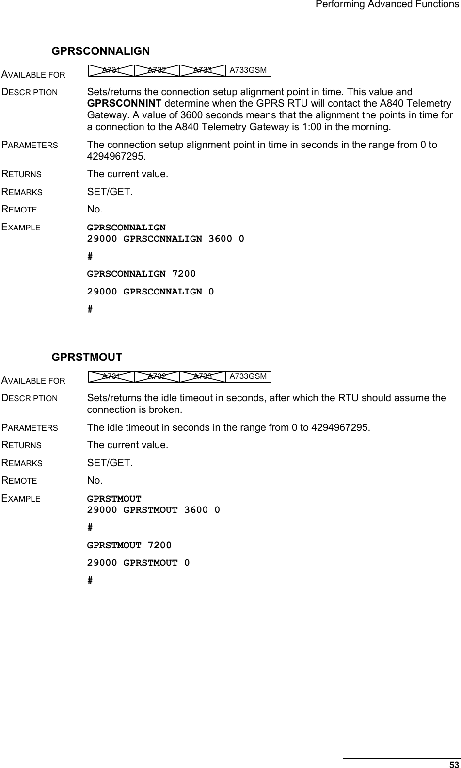
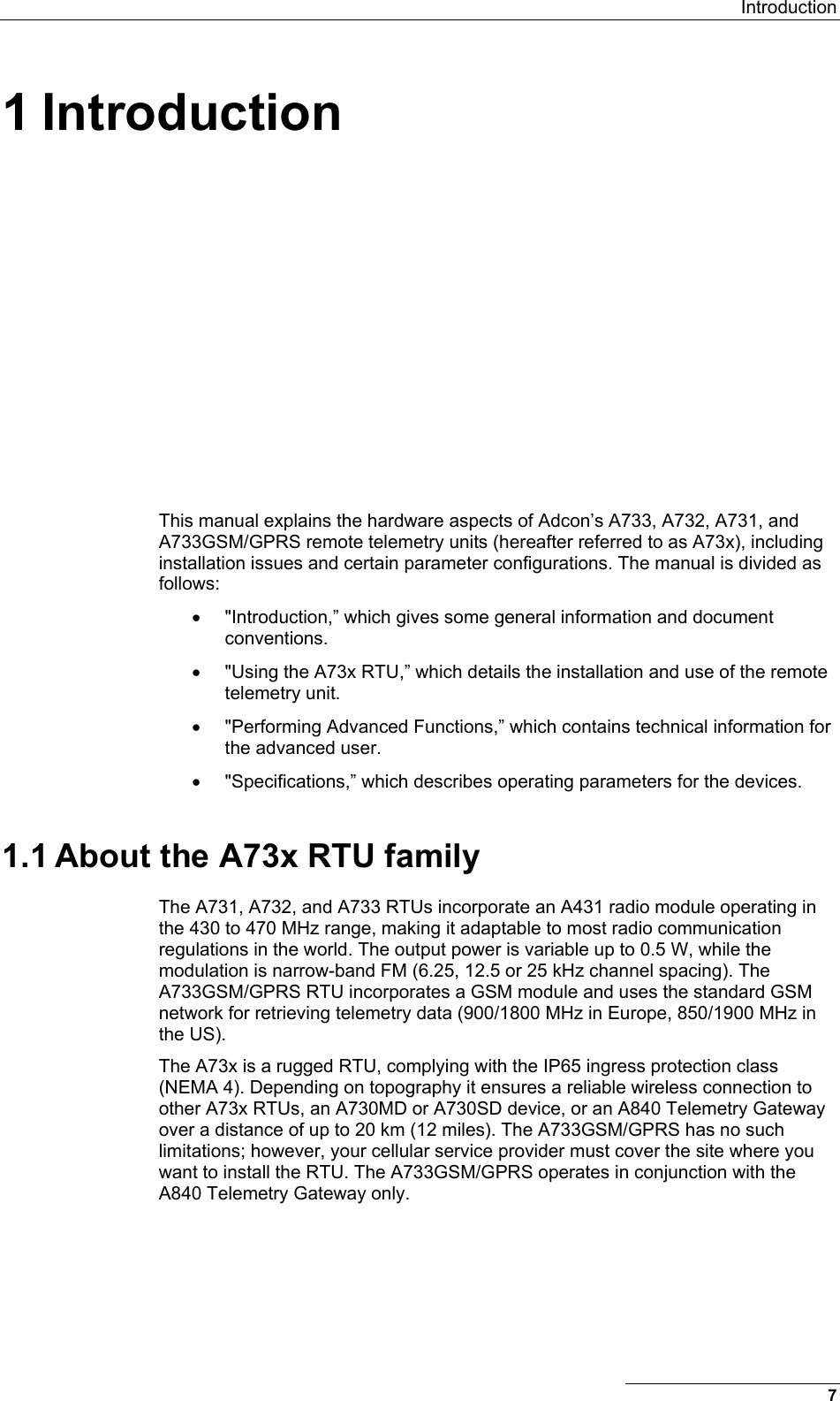
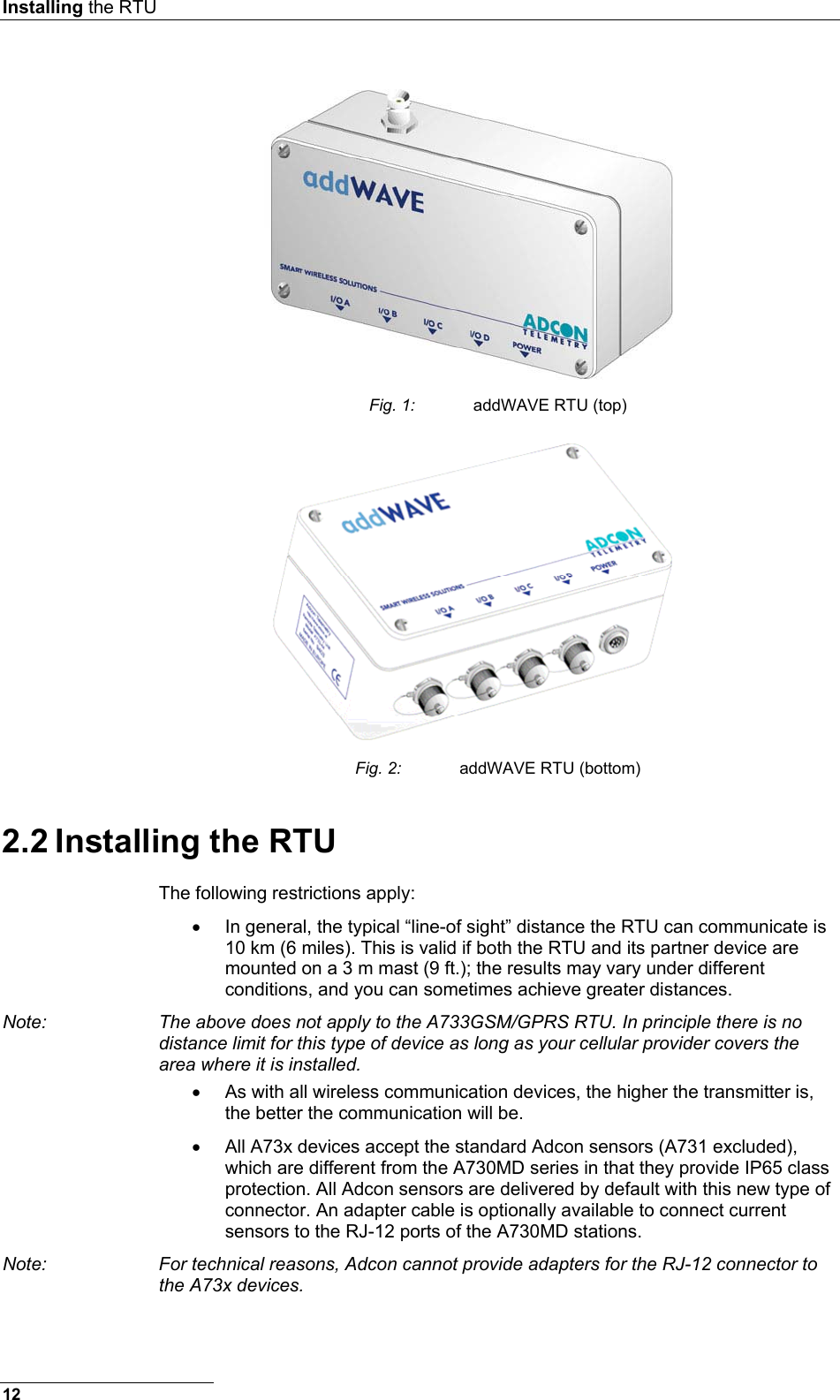
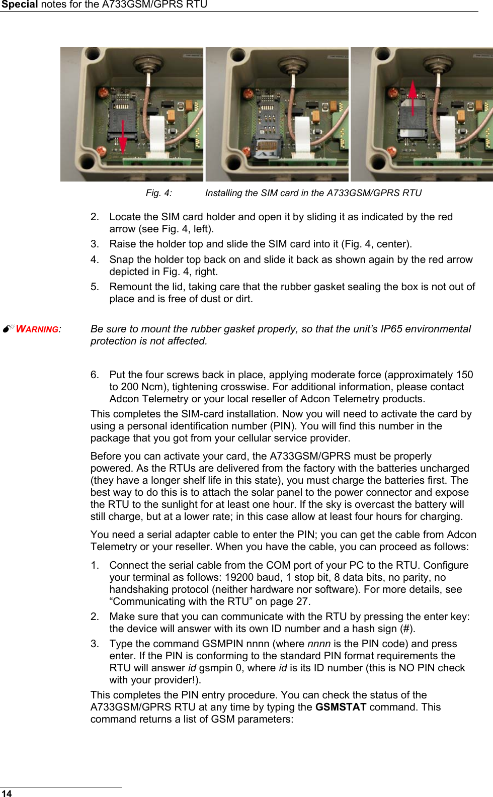
![Using the A73x RTU Configuring the RTU GPRS Connection settings Use the following commands to define the intervals the RTU will wake up and connect to the A840 Telemetry Gateway: GPRSCONNALIGN [align] alignment of calls in seconds (default 28800, i.e. 8:00). NOTE: These wall clock times are either UTC or local time of your A840 Telemetry Gateway, depending on the setting of the “Wireless Network uses:” switch on your A840 Telemetry Gateway. GPRSCONNINT [interval] interval between two connection attempts in seconds (default 43200, i.e. 12 hours). GPRSSECRET <secret> this 32-bit integer (0 to 4294967295) has to be set for the RTU and the gateway. This is a shared “secret” or password. GPRSTMOUT [interval] idle time out in seconds (default 3600, i.e. 1 hour). Connections that are idle this long will be terminated by the RTU. Set these parameters according to the needs of your application. Make sure you choose the proper parameters for GPRSTMOUT (to allow for appropriate idle times, but not ones that are too long), GPRSCONNALIGN and GPRSCONNINT (for specifying the proper connect times of the RTU). Also take into account, that the RTU will be polled for data by the Adcon Telemetry Gateway within the GPRSTMOUT time. If you need your RTU to detect within an hour that the connection to the Adcon Telemetry Gateway is broken, set the GPRSTMOUT to 3600 seconds. But make sure, that the RTU is polled for data at least once within that time span. Note: Keep in mind that "calling" the A840 Telemetry Gateway costs battery power. Recommended Settings for A733 GSM/GPRS with WaveCOM Module: On the RTU: • GPRSCONNINT 3600 or 7200 or 10800 (1, 2, 3 hours connection interval) • GPRSCONNALIGN is per default set to align the connection to 8:00 (UTC) On the gateway: • Check the "Close connection after poll" checkbox for the RTU 2.4 Field Installation Installing A73x RTUs in the field is a fairly simple process. You’ll perform a connectivity check with an LED tool (does not apply to A733GSM/GPRS RTUs). The LED tool is shown in Fig. 5. 17](https://usermanual.wiki/Ott-Hydromet-Business-Unit-Adcon-Telemetry/A733GSM-GPRS/User-Guide-753716-Page-17.png)