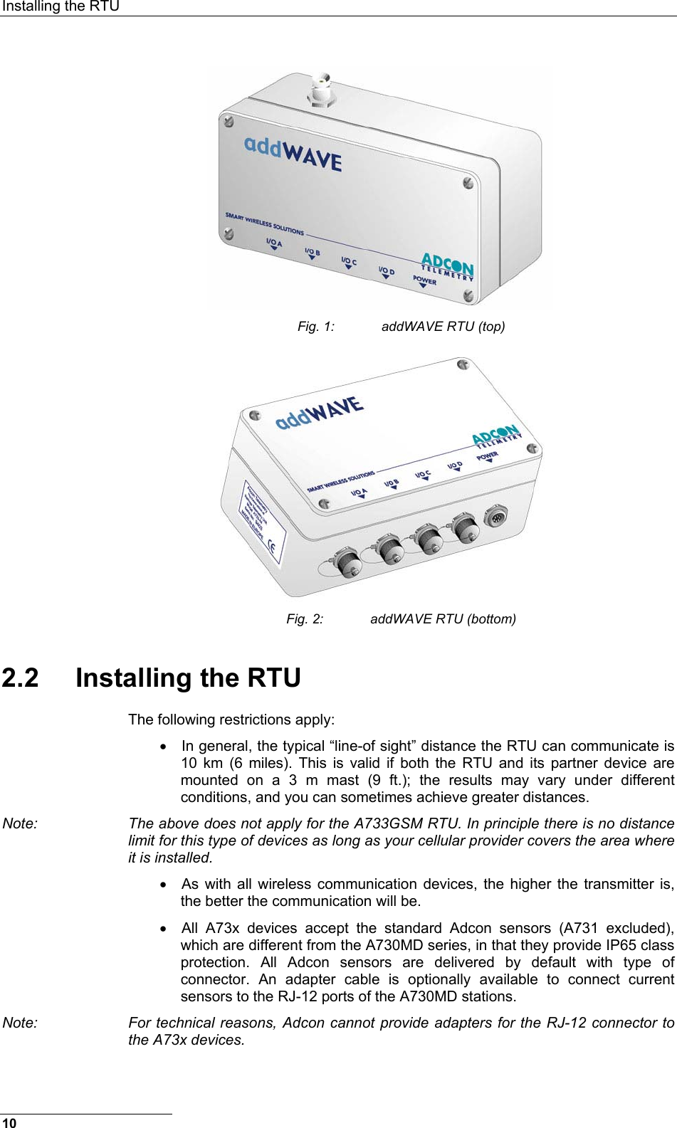
Ott Hydromet Business Unit Adcon Telemetry A733GSM-USA Telemetry device using GSM/DCS technology User Manual A733 UserGuide English V21 01
Adcon Telemetry GmbH Telemetry device using GSM/DCS technology A733 UserGuide English V21 01
UserManual.wiki
>
Ott Hydromet Business Unit Adcon Telemetry
>
A733GSM USA User Manual
User manual
Navigation menu
Upload a User Manual
Namespaces
Wiki Guide
HTML
PDF
Info
Views
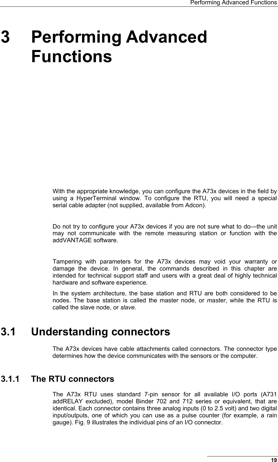
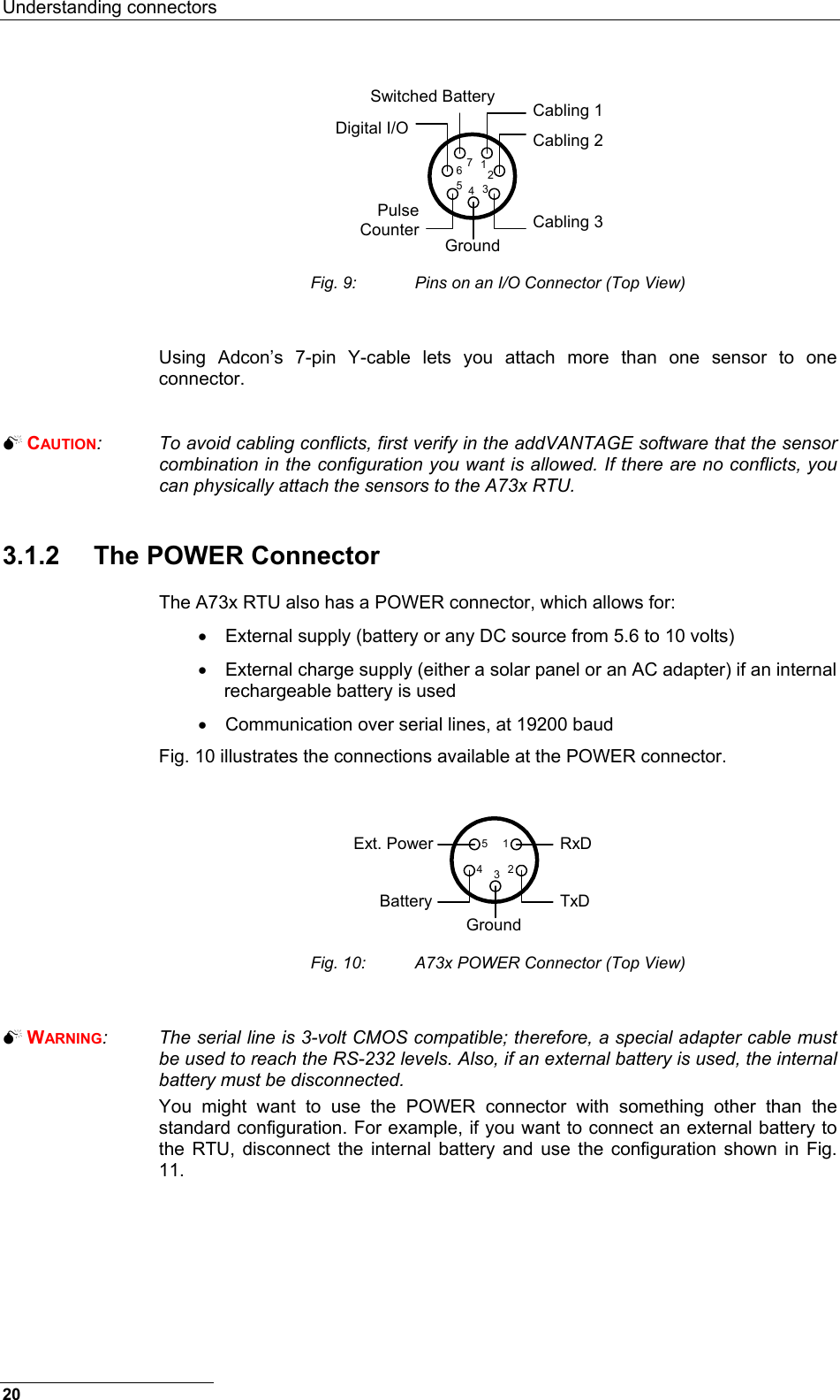
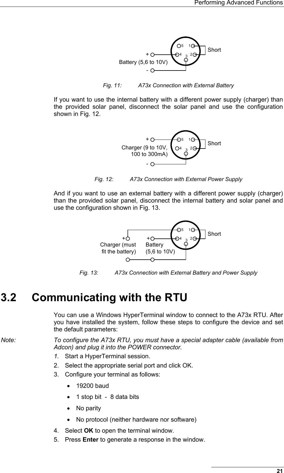
User Manual
Discussion / Help
Navigation