Ott Hydromet Business Unit Adcon Telemetry A751-46 Telemetry transceiver User Manual A75x User Manual 72
Adcon Telemetry GmbH Telemetry transceiver A75x User Manual 72
UserManual.wiki
>
Ott Hydromet Business Unit Adcon Telemetry
>
A751 46 User Manual
User manual
Navigation menu
Upload a User Manual
Namespaces
Wiki Guide
HTML
PDF
Info
Views
User Manual
Discussion / Help
Navigation

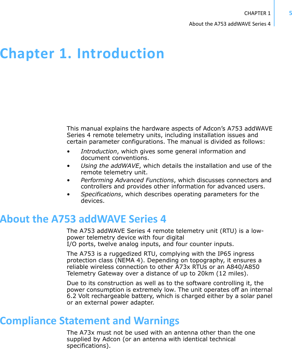
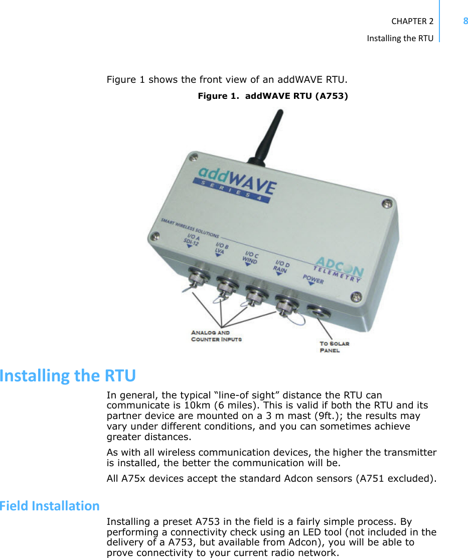
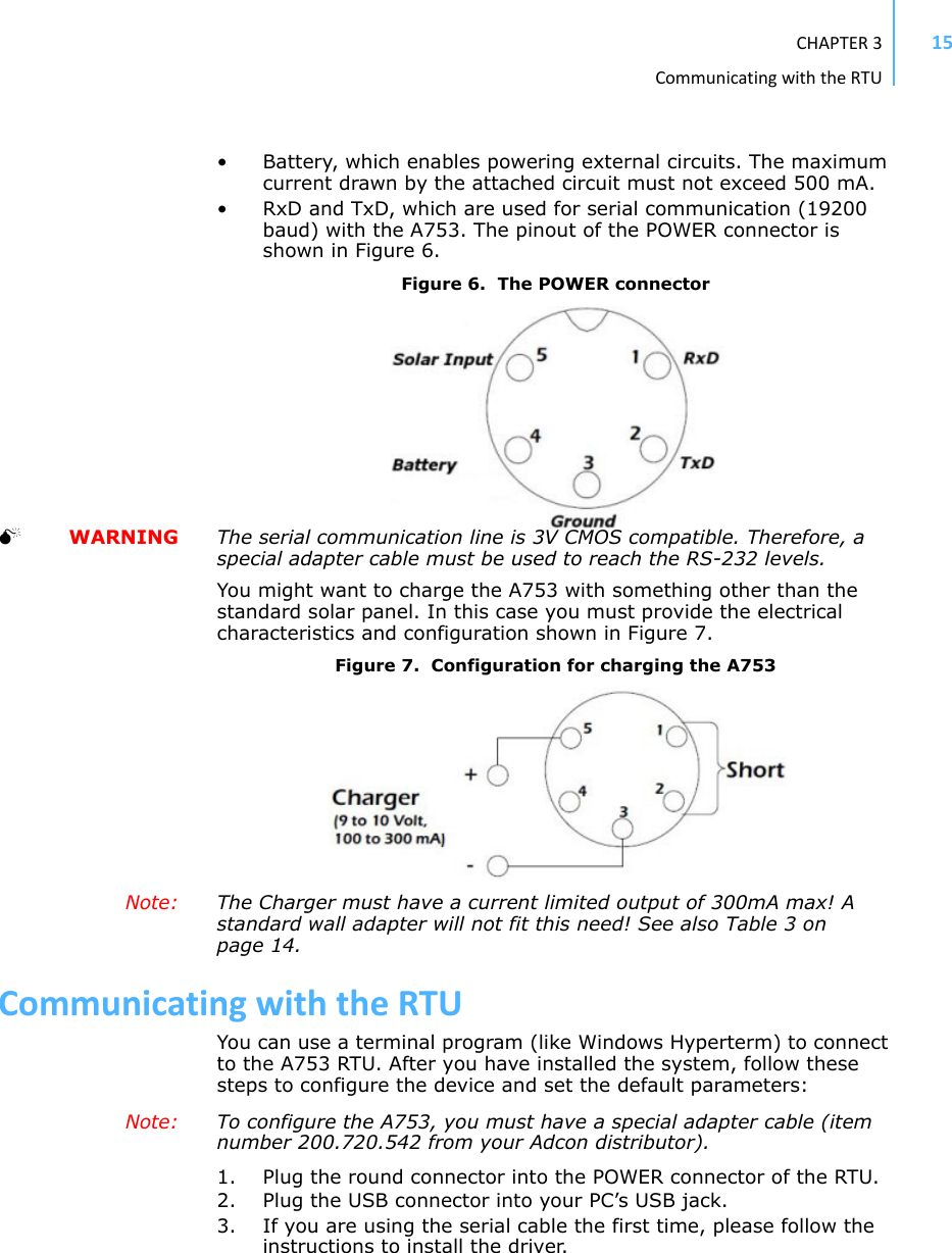
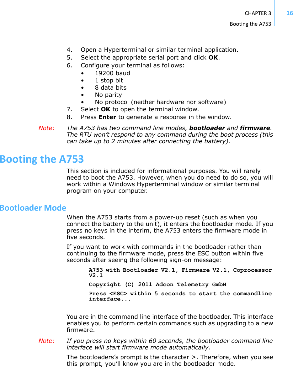
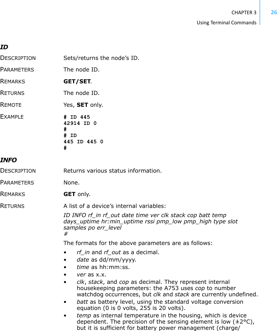
![CHAPTER3BootingtheA75317CommandsavailableinBootloaderModeFor a list of the available commands, type HELP at the > prompt.Note: Square brackets (like “[arg]” or “[arg1 arg2]”) enclose optional arguments,which may be omittedHELPAvailable commands:upgrade [type] [baudrate] ... upgrade (firmware/coprocessor, 19200/115200)version ... show the version of the bootloaderstate ... show the board statereboot [id] ... reboot the RTUfirmware ... start the firmwarehelp ... display this helptext0>Note: The output of the HELP command may differ depending on the RTU type.The STATE command can be used to check the battery level, solar charger state and the RTU’s current temperature.STATEBattery: 6.2 V (full charge)Temperature: 26 degree Celsius0>FirmwareModeWhen you enter firmware mode by typing the command FIRMWARE, the following message is displayed in the Hyperterminal window:FIRMWAREChecking firmware ........... found!Checking storage ............... ok!46339 0#The bootloader scans the program memory for a valid firmware by testing the checksum, which takes a moment. If everything is correct, the "firmware found!" message appears.](https://usermanual.wiki/Ott-Hydromet-Business-Unit-Adcon-Telemetry/A751-46/User-Guide-1576926-Page-17.png)
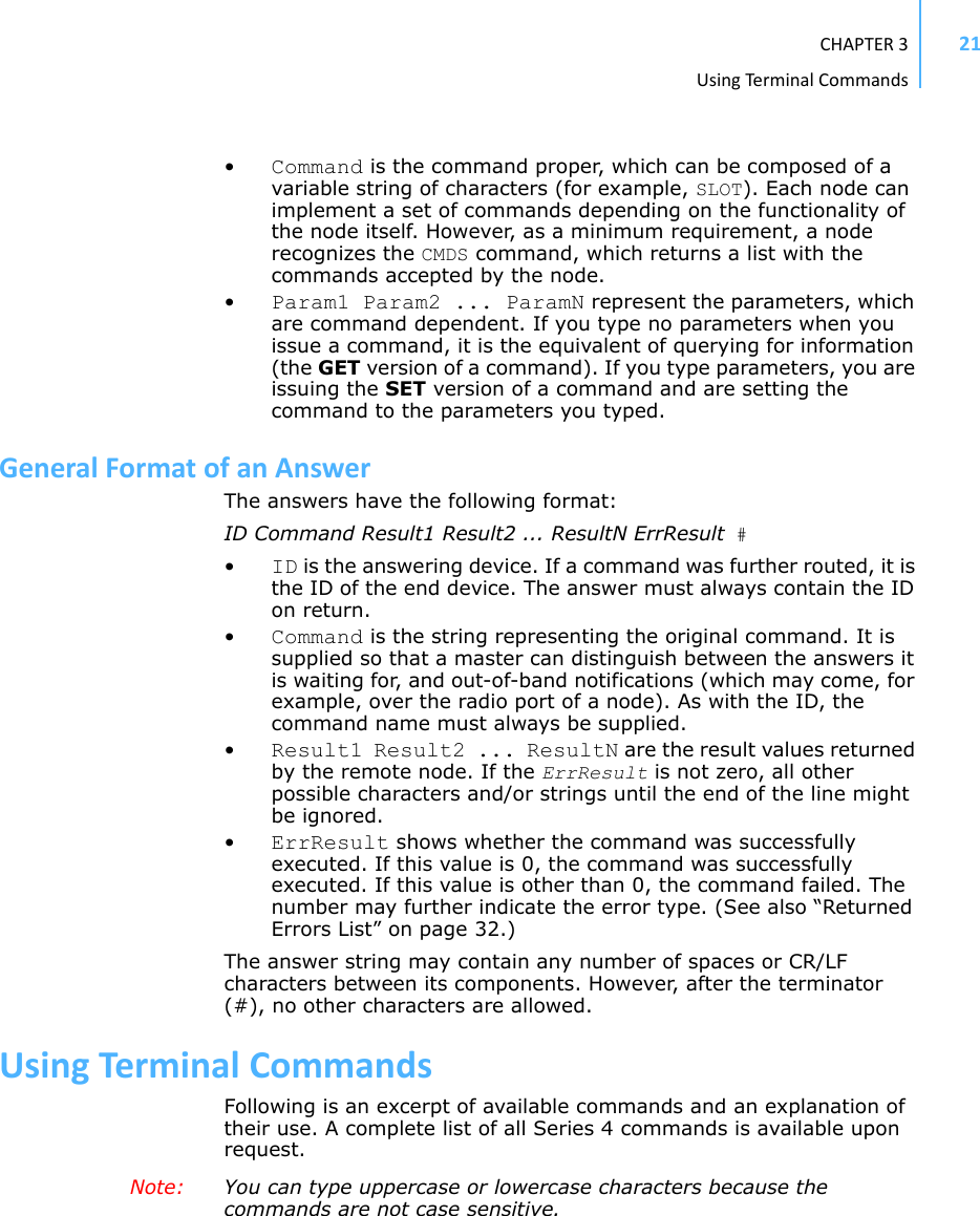
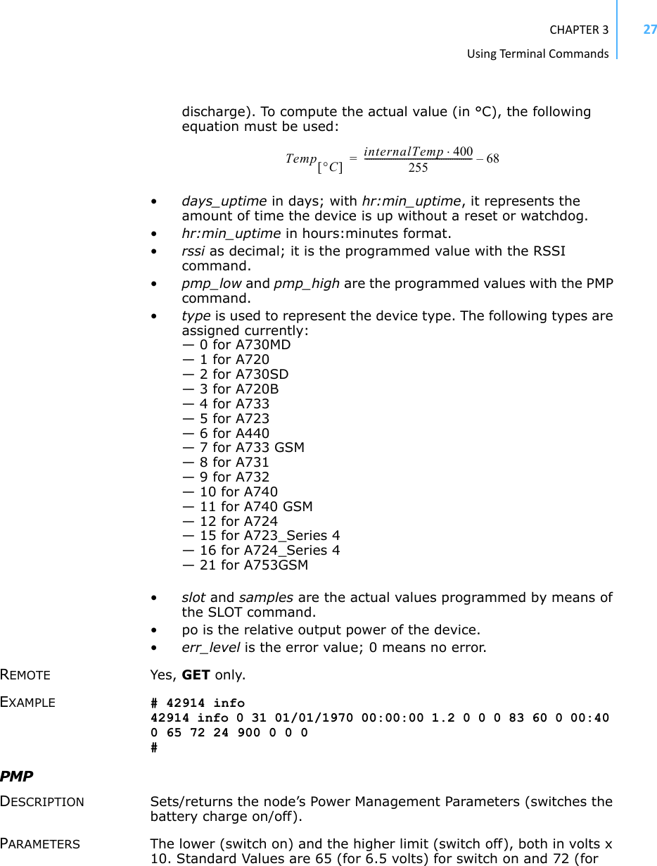
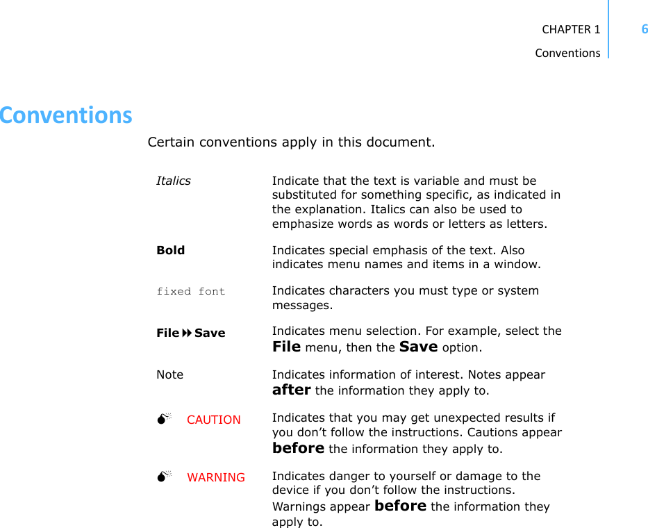
![CHAPTER3UpgradingtheFirmware194. Click the Configure button to display the com port’s Properties dialog (Figure 8 shows a COM1 com port).Figure 8. Hyperterminal and com port properties dialogs5. In the Bitspersecond field, select 115200.6. Select OK in the com port’s Properties dialog to close it.7. Select OK in the hyperterminal’s Properties dialog to close it.8. Back in the hyperterminal window, press Enter to continue the upgrade.---------------------------------------------------The current firmware image must be erased for the upload.If you continue now, you *MUST* upload a valid firmware image for an A753!Continue? [y/n]: WARNING When you continue with the upgrade process, any existing firmware image in the A753’s flash memory will be erased! You must supply a valid image for upload or the A753 will have only bootloader capabilities (that is, it will have no radio capabilities).9. Enter Y to continue the upgrade.The bootloader starts sending the letter C (for connect)](https://usermanual.wiki/Ott-Hydromet-Business-Unit-Adcon-Telemetry/A751-46/User-Guide-1576926-Page-19.png)