Otto Bilz and HFS3000-49 Wireless Machine Tapping Control System User Manual Manual
Otto Bilz GmbH & Co. Wireless Machine Tapping Control System Manual
Manual

BA140.1 I
k
GmbH
& Co
Eln
Unternehmen dcr
LEITZ
METALWORKING TECHNOLOGY GROUP
Notes to the FCC authority
to
oDerate
the equipment
This device complies with Part 15 of the FCC Rules. Operation is subject to the
following two conditions:
(l)This device may not cause harmful interference, and
(2)thi.s
device must accept any interference received, including interference that
may cause undesired operation.
Caution:
Changes or modifications not expressly approved by the party responsible for
compliance could void the user’s authority to operate the equipment.
This equipment has been tested and found to comply with the limits for a Class B
digital device, pursuant to Part 15 of the FCC Rules. These limits are designed to
provide reasonable protection against harmful interference in a residential instal-
lation. This equipment generates, uses and can radiate radio frequency energy
and, if not installed and used in accordance with the instructions, may cause
harmful interference to radio communications. However, there is no guarantee
that interference will not occur in a particular installation. If this equipment does
cause harmful interference to radio or television reception, which can be deter-
mined by turning the equipment off and on, the user is encouraged to try to cor-
rect the interference by one or more of the following measures:
l
Reorient or relocate the receiving antenna.
l
Increase the separation between the equipment and receiver.
l
Connect the equipment into an outlet on a circuit different
fi-om
that to which
the receiver is connected.
l
Consult the dealer or an experienced radio/TV technician for help.
IIZ
Werkzeugfabrik
GmbH
&
Co .
Ust-IdNr
DE 145355716 . Hand®ister
Essllngen
a N HRA 313 .
VogeisangstraRe
8 . 73760
Ostfildern
. Postfach 1155 .73747
Ostflldern
Telefon
+
49 (0) 711 3 48 01-O
-
T&fax
+ 49 (0) 711 3 48 12
56
. C-mall
anfo@btlz
de .
Homepage
http
iiwww
bllr
de
Personlich
haftende
Gesellschafterln
Bilz
GmbH
.
Handelsreglster
Esslingen
a N HRB 1759 .
Geschaftsfuhrer
Rwner
BIIZ
Michael Voss
,bank
Essllngen
BLZ 611 400 71 Kto 8 264 780.
Baden
Wurttemberglsche
Bank
Aalen,
BLZ 600 200 30 Kto
8
960 902 800 .
Deutsche
Bank
Esslingen
BLZ 611 700 76 Kto 102 012

BA140.11
Ein
Unternehmen
dcr
Lirll~Z
METALWORI<ING
TECHNOLOGY GROUP
HF Wireless Tappim Control Unit HF 3000
OPERATING INSTRUCTION
1 Layout Diagram: HF Wireless Tapping Control Unit HF 3000
3
2 Introduction
3 The HF transmitters
3.1 Transmitter “HFS 3100”
3.1.1 Operational Modes of HF Transmitter
3.1.2 Battery replacement
3.2
Transmitter “HFS 3000”
3.2.1 Operational Modes of HF Transmitter
3.2.2 Battery replacement
3.3 Technical data
4 The
HF
Receivers “HFE 3002” and “HFE 3004”
3
4
4
4
4
4
4
4
5
6
4.1 Operating Elements of HF Receiver and their Functions
6
4.2 Operational and Alarm Modes of HF Receiver
8
4.2.1 Mains operated
8
4.2.2 Standby operational mode
8
4.3
Mains Voltage Setting
9
4.4
Technical Data
9
4.5 Remote Control of Receiver by Programmable Logic Control
10
4.5.1
Wiring explanations
10
4.5.2 Status schedule of relaycontacts
10
4.5.3 Wiring Diagram of HF Receiver
10
4.5.4 Realisation of Remote Control Operation
11
4.5.5 Actions at alarm
11
5
The HF Receiver “HFC
70” 12
6 Installation
13
6.1 General Information
13
6.2
Assembly
13
6.2.1 Front mounting of receiver in the switchboard
14
6.2.2 Mounting of receiver with sliding blocks for handle and feet slots
14
7 Maintenance
16
7.1 Quarterly Maintenance
16
7.2
Semi-annual Maintenance
17
8 Annex
18
8.1 Frequency Table
18
8.2 Homologations
19
8.3 Check-list for HF Tapping Alarm Control Unit system 3000, in case of HF alarm
20
-
_._
,
#IL
Werkreugfabrlk
GmbH
&
Co .
Ust-IdNr
DE 145355716 .
Handelsreglster
Essilngen
a N HRA 313 .
VogelsangstraRe
8
. 73760
Ostflldern
. Postfach 1155 . 73747
Ostfbldern
Telefor~
+ 49
(0)
711
3 48 01-O .
T&fax
+ 49 (0) 711 3 48 12 56 . E-mall
mfo@bllz
de
*
Homepage
http
iiwww
bllz
de
Personllch
haftende
Gesellschafterin
BIIZ
GmbH
.
Handelsreglster
Essllngen
a N HRB 1759 . Geschaftsfuhrer
Remer
Bllr,
Michael
Voss
rbank
Essllngen,
BLZ 611 400 71 Kto 8 264 780 .
Baden
Wurttemberglsche
Bank
Aalen,
BLZ 600 200 30, Kto 8 960 902 800 .
Deutsche
Bank
Esslmgen
BLZ 611 700 76 Kto 102 012
BA140.11
Page 3
01/22/2001
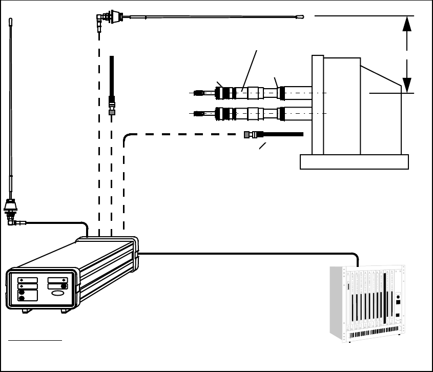
1 Layout Diagram: HF Wireless Tapping Control Unit HF 3000
2 Introduction
HF Tapping Control Unit (HF = High Frequency)
When tapping on transfer lines, special purpose machines and machining centers, damage of the tap cannot al-
ways be prevented. Occasionally, the threads are not tapped to full depth or are missing at all. Such faults remain
often undetected until assembling of the parts. This causes high remachining costs and means sometimes even the
rejection of the component. In combination with the BILZ WFL, WFLK or WFLP Quick Change Tapping
Chucks and Adaptors with safety clutch, the HF unit controls the thread depth, identifies possible tap breakage
during tapping operation and prevents such malfunctions.
max. 3 m
HFA 0
receiving antenna
HFA 2
adaptor with
safety clutch
tapping unit
transmitter
antenna
chuck with
length compensation
receiving antenna HFA 2
HF-RECEIVER
ALARM POWER
BILZ
B.-CHECK
LEVEL
RESET
POWERALARM
HF-receiver
HFE 3002: 2 antenna inputs
HFE 3004: 4 antenna inputs machine control
coaxial cable
x = length in meter
(max. 25 m)
HFK 2.x
multiple cable to machine control
(optional length)
HFK 0.x
HFK 0.x
receiving antenna
HFA 0
BA140.11
Page 4
01/22/2001
3 The HF transmitters
3.1 Transmitter ”HFS 3100”
3.1.1 Operational Modes of HF Transmitter
Collision alarm Battery monitoring alarm
Alarm triggering:
Chuck is compressed in the clockwise direction or
extended in the anticlockwise direction
Alarm triggering:
Battery voltage drops below 3.0 V.
Reaction:
HF signal in 1 sec. rhythm Reaction:
HF signal in .5 sec. rhythm.
End of alarm:
Collision alarm is cancelled 5 sec. after chuck release.
Transmitters of extended transmittal time are available
on request
End of alarm:
Battery monitoring alarm can be cancelled only
by removing the empty battery.
As long as no alarm is being triggered the HF transmitter is in inoperative position and requires max.
20 µA of energy.
3.1.2 Battery replacement
As soon as a battery monitoring alarm is being triggered, the battery is to be replaced immediately.
• Remove from spindle the chuck having triggered battery monitoring alarm (for identification see 4.2.1), dry it
up and unscrew plug screw from shank.
• Remove empty battery and replace it by a new one.
Attention: Insert battery with negative pole (-) towards open end of shank.
For replacement purposes use only lithium-thionyl-chloride batteries, size ½AA
(preferably Sonnenschein SL-750/S).
• Screw in again shank plug screw.
3.2 Transmitter ”HFS 3000”
3.2.1 Operational Modes of HF Transmitter
Collision alarm Battery monitoring alarm
Alarm triggering:
Chuck is being compressed Alarm triggering
Battery voltage drops below 3,1 V.
Reaction:
Permanent HF signal Reaction:
Permanent HF signal
End of alarm:
Alarm is being cancelled only after releasing the chuck End of alarm:
Battery monitoring alarm can be cancelled only by
removing the empty battery.
As long as no alarm is being triggered the HF transmitter is in inoperative position and requires max. 20 µA of
energy.
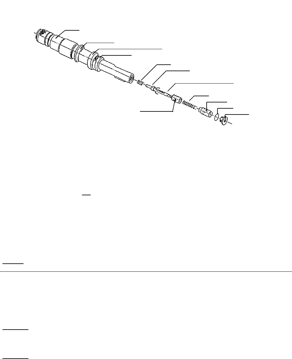
3.2.2 Battery replacement
As soon as a battery monitoring alarm is being triggered the battery is to be replaced immediately.
• Remove from spindle the chuck having triggered battery monitoring alarm (for identification see 4.2.1), dry it
up and unscrew plug screw from shank.
• Remove batteries and test voltage using battery tester: minimum 3.0 V.
• Replace empty batteries by new ones.
• Remove transmitter from shank by pulling it downward; do not lose spring of switch pin .
• Visual inspection of transmitter:
1. for humidity and corrosion
2. for integrity of contact bow.
BA140.11
Page 5
01/22/2001
• Putting back the transmitter into the chuck:
1. Place the spring on the switching pin and push the transmitter back into the shank hole from the bottom
towards the top.
2. Insert batteries with the positive pole to the open end of the shank. 3 mercuryoxide batteries are needed
for replacement purposes (according to IEC NR07, NR44 or ANSI N15 resp. USASI M15) e.g.:
Varta V675HP, Mallory M P 675 H, Daimon/Berec MP675H, Ucar EP 675E, FDH 675E.
Zinc-air batteries must not be used.
All of the 3 batteries are to be replaced at the same time.
3. Replace O-ring on the screwplug each time the plug had been unscrewed. Screw plug is to be tightened
with 5 to 6 Nm.
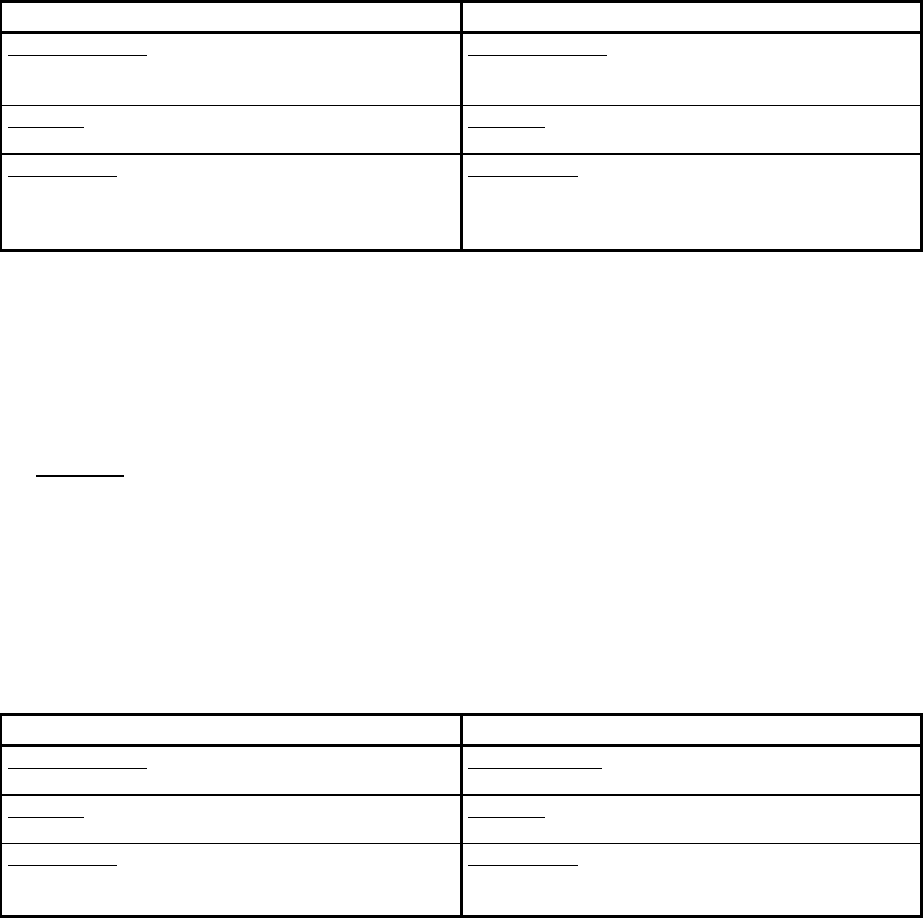
3.3 Technical data
General
Country FRG U.K. USA USA Sweden
frequency range 70.00-72.00 49.82-49.98 49.83-49.89 72.00-72.99 30.27-30.34 MHz
channel spacing 80 16 15 30 30/40 kHz
transmitting range (distance chuck - antenna) abt. 3 m
HF-output < 1 nW
permissible ambient temperature 0 - 80 °C
HFS 3100
Power source: lithium thionyl chloride battery 3.6 V
Battery capacity 850 mAh
HFS 3000
Power source: 3 mercury batteries 1.4 V each 4.2 V
Battery capacity 240 mAh
spring
chuck
detector ring
transmitting antenna (yellow)
adjusting nut
transmitter
No. of transmitting channel
plastic bushing
spring
batteries
O-ring
plug screw

BA140.11
Page 6
01/22/2001
4 The HF Receivers ”HFE 3002” and ”HFE 3004”
4.1 Operating Elements of HF Receiver and their Functions
a) Front panel of the unit
Element: Function:
S1 ”RESET” button A signal emitted by a chuck will be memorized
by the receiver. Pushing ”RESET” button will
clear the receiver.
D12 Yellow ”B.-CHECK” indicator Lights up only as long as a signal emitted by
one of the chucks on this receiver’s channel is
being received.
D13 Red ”ALARM” indicator Informs that a signal emitted by one or several
chucks on this receiver’s channel has been and/or
is being received.
D14 Green mains indicator Lights up when power is switched on.
BU1 (-), BU2 (+) Level output The strength of the HF signal received (level) can
be measured by voltmeter. The level depends on
antenna’s positioning (see 6.2).
b) Rear panel of the unit
ALARM
B.-CHECK
LEVEL
RESET
POWER
BILZ
HF-RECEIVER
D12 D13 D14 S1
BU1 BU2
X6 X1
X2 X3 X4 X5

BA140.11
Page 7
01/22/2001
Element: Function
X1 Multiple connector Ten pin plug for Harting socket HAN 10 A for
remote control of the receiver, see below and 4.5.
The socket is to be inserted all the time. If remote
control isn’t needed, please install bridge (part of our
supply).
X2, X3, X4, X5 Antenna inputs Coaxial socket type N with an impedance of 50 Ohm.
The receiver ”HFE 3002” is being equipped with
the two antenna inputs X2 and X3 only.
X6 Mains connection Mains connection of abt. 1.8 m incl. line plug. To
change mains voltage shift bridges on printed board
inside the receiver.
Assignment of multiple connector X1:
Element: Function
X1 comprises:
REL1 Normally closed contact ”B.-CHECK” contact, open when signal from tool is
being received.
REL2 Normally closed contact ”ALARM” contact, open when signal from one or
several chucks on this receiver’s channel has been
and/or is being received.
REL4 Operating contact Power contact, closed when power supply is switched
on.
9
10
1
2
3
4
5
6
2
REL2
3
REL4
1
REL1
R1.1
Remote control connection
multiple connector X1
To machine control
multiple socket (type HAN 10A)
B.-CHECK
ALARM
POWER ON
4
COM
5
6
7
8
RESET
HFREL
GND
7
8
9
10
R2.1

BA140.11
Page 8
01/22/2001
4.2 Operational and Alarm Modes of HF Receiver
4.2.1 Mains operated
Collision alarm Battery monitoring alarm
Yellow ”B.-CHECK” indicator and ”REL1” contact:
Transmitter HFS 3000 Transmitter HFS 3100 Transmitter HFS 3000 Transmitter HFS 3100
As long as an alarm signal
is being received,
”B.-CHECK” indicator
lights up.
”REL1” contact: open.
As long as an alarm signal
is being received,
”B.-CHECK” indicator is
flashing in 1 sec. rhythm.
”REL1” contact opens and
closes in the same rhythm.
As long as an alarm signal
is being received,
”B.-CHECK” indicator
lights up.
”REL1” contact: open..
As long as an alarm signal
is being received,
”B.-CHECK” indicator is
flashing in .5 sec. rhythm.
”REL1” contact opens and
closes in the same rhythm.
Red ”ALARM” indicator and ”REL2” contact:
As soon as the HF receiver has identified an alarm signal, the ”ALARM” indicator lights up and the ”REL2” con-
tact opens.
This situation will remain unchanged even after alarm signal ends, until the receiver will be reset by pushing
RESET button of its front panel or by opening the bridge between pins 8 and 10 of the multiple plug X1.
Recognition of faulty thread spindle in case of collision alarm:
All HF transmitters in the chucks of one multi-spindle tapping station can operate on the same frequency, i.e. on
the same channel. To recognize the spindle of the faulty thread, the chuck shanks are equipped with detector
rings. When the length compensation of a chuck gets compressed, the detector ring will be moved upwards and
thus identifies the spindle of the faulty thread. After correction, the detector ring is to be pushed back by hand
into zero position. Minimum compression length to get a signal response from the chucks is 1 mm (.04”).
Recognition of the spindle with battery monitoring alarm:
In case of alarm, all chucks are to be released first. If luminous diode ”B.-CHECK” continues lighting or flashing
(HFS 3100): A battery monitoring alarm has occurred. The individual chucks of the different spindles are to be
compressed now in succession. When compressing the chuck giving battery monitoring alarm, luminous diode
”B.-CHECK” will discontinue to give light. When compressing any other chuck, the luminous diode
”B:_CHECK” will continue to light up resp. to flash.
The chuck giving battery monitoring alarm can be identified much easier by using the HF receiver
”HFC 70”.
After recognition of the chuck having caused battery monitoring alarm and after battery replacement, the detector
rings are to be pushed back into zero position.
4.2.2 Standby operational mode
During intermissions (mains cut off) the receiver switches on periodically for short moments, to check if one of
the chucks is emitting battery monitoring alarm and, if any, memorizes it. During stand-by neither the indicator
diodes of the front panel nor the remote control relays are being activated. A fully loaded buffer battery
allows to maintain stand-by for abt. 3 weeks. After switching on again electricity supply system, the alarm indi-
cating diodes of the receiver’s front panel are being switched on, too, and the remote control relays are being
activated as well.
Recognition of the chuck having caused battery monitoring alarm, after switching on mains supply:
Weak battery Empty battery
• Red ”ALARM” indicator lights up.
• Yellow ”B.-CHECK” indicator lights up or
flashes in .5 sec. rhythm (HFS 3100).
• Red ”ALARM” indicator lights up.
• Yellow ”B.-CHECK” indicator does not light up.
see chapter 4.2.1 Check all chucks by compressing one after another.
• Active battery: ”B.-CHECK” lights up or flashes in
1 sec. rhythm (HFS 3100).
• Empty battery: ”B.-CHECK” doesn’t light up.
BA140.11
Page 9
01/22/2001
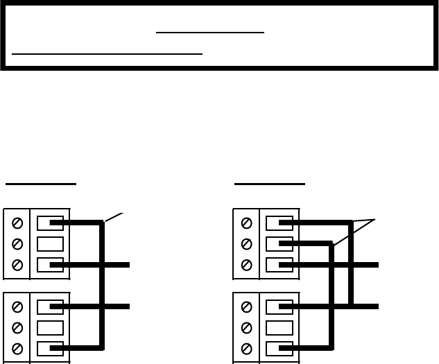
4.3 Mains Voltage Setting
SI Fuse socket To change mains fuse, remove cover, replace fuse
(63 mA, slow), put back cover.
SK1, SK2 Screw clips To connect mains supply.
4.4 Technical Data
Mains voltage 115 V +/- 10 % or 230 V +/- 10 %
Mains frequency 50 - 60 Hz
Fuse (slow) 63 mA
Power consumption 6.9 VA
Battery voltage 12 V
Battery capacity 280 mAh
Permissible ambient temperature 0 - 65 °C
Recommended antennae HFA 0 and HFA 2
Relay contact rating 230 V / 2 A
Sensitivity - 90 dBm
Adjacent channel suppression (40 kHz separation) > 40 dB
Number of channels per receiver 1
Number of antenna connections per receiver
HFE 3002 2
HFE 3004 4
Antenna impedance 50 Ohm
Degree of case protection IP54
Dimensions Width * Height * Length
160 * 98 * 340 mm
6.3 * 3.9 * 13.4 inch
Weight 2.4 kg
5.3 pound
ATTENTION!!!
Disconnect mains supply before opening equipment!!!
SK1
SK2 SK2
SK1
L
N
wire bridge
L
N
230 V: 115 V:
wire bridges

BA140.11
Page 10
01/22/2001
4.5 Remote Control of Receiver by Programmable Logic Control
4.5.1 Wiring explanations
R1, R2 Relay
R1.1 Normally closed contact of relay R1, controlled by one of the PLC outputs
R2.1 Main contact of relay R2, controlled by one of the PLC outputs
E1, E2, E3 Inputs of PLC
A1, A2, A3 Outputs of PLC
VS Voltage supply, up to 230 V
GND Ground wire of voltage supply
REL1, REL2 Normally closed contacts of the relays inside the receiver
REL4 Main contact of REL4 relay inside the receiver
4.5.2 Status schedule of relaycontacts
Contact REL1
B.-CHECK REL2
ALARM REL4
POWER ON
No power supply
closed closed open
Power supply switched on and:
no signal received so far closed closed closed
signal is just being received open open closed
signal was received closed open closed
reset when just no signal is being received closed closed closed
The receiver is memorizing the reception of a signal until reset by front panel button or by reset input on
remote control connection, respectively.
4.5.3 Wiring Diagram of HF Receiver
COMMANDE
PROGRAMMABLE
(SPS)
programable logic control
(PLC)
8
4
1
3
2
REL1
REL4
REL2
R1.1
POSTE-
RÉCEPTEUR HF
HF-Receiver
E1
E2
E3 }ENTRÉES SPS
PLC-inputs
VS SOURCE DE TENSION
Voltage source
GND Masse / Ground
A1
A2
SORTIES SPS
PLC-outputs
10
PONT OU R1.1
wire bridge or R1.1
SCHÉMA DE CÂBLAGE POUR TÉLÉCOMMANDE
Wiring diagram for remote operation
B.-CHECK
POWER ON
ALARM
COM
RESET
GND
9
HFREL A3 R2.1

BA140.11
Page 11
01/22/2001
4.5.4 Realisation of Remote Control Operation
• Wire receiver according to wiring diagram of chapter 4.5.3.
• PLC supervises inputs E1, E2, E3.
• When not operated (mains supply connected), inputs E1, E2, E3 are connected to VS.
Input Function Source of signal at receiver
E1 B.-CHECK Output 1
E2 Mains Output 3
E3 ALARM Output 2
Output Function Action
A1, A2 Reset of receiver Bridge between receiver’s inputs
8 and 10 is being opened
A2, A3 HF reception suppressed Bridge between receiver’s inputs
9 and 10 is being closed
After a malfunction signal and the necessary steps, the machine control cancels the signal. For that purpose PLC
will activate the contact R1.1 for a short moment (> .1 sec).
4.5.5 Actions at alarm
Program step K
Error signal at
input E3?
Retract the unit,
release all chucks
Alarm of
collision detection
Sight ring is shifted
Check tool and workpiece
replace if necessary
Reset
HFE 3002 / HFE 3004
Shift sight rings
to zero position
yes
no
Battery
monitoring
alarm
yes Compress each tool
in succession
yes
Replace battery
of this tool
Program step K+1
no
no
Error signal at
input E1?
Error signal at
input E1?
Reset
HFE 3002 / HFE 3004
Shift sight rings
to zero position
During this actions at alarm, the bridge
between pins 9 and 10 of the HARTING
socket must be open.

BA140.11
Page 12
01/22/2001
5 The HF Receiver ”HFC 70”
The use of the HF receiver ”HFC 70” is of help to easily identify a chuck having caused battery monitoring
alarm.
Such chuck can be identified by making contact to the transmitting antenna (yellow ring) of the chuck by the
”HFC 70” antenna.
Operating elements of the hand-held receiver
• ON button:
Hand held receiver is switched on as long as ON button is being pushed.
• Indication of signal level (by LED):
The level of the signal received by the stub antenna is being shown by LED row. A distinct deflection will be
seen only after the antenna bar has nearly touched the antenna ring on the chuck.
• Battery check:
A red LED in the left corner of the LED row is determined to show operating readiness:
fully charged battery:
when pushing ON button: LED lights up for a short moment
weak battery:
when pushing ON button: LED doesn’t light up
The battery is of standard 9 V bloc type.
ON
HFC70
antenna
ON button
LED indication
battery
check

BA140.11
Page 13
01/22/2001
6 Installation
6.1 General Information
The HF receiver is protected against interference pulses. Normally adjacent electrical motors, transformers, con-
trols, radios etc. will not cause alarm signals. On the operating frequency, interference signals must not exceed
the maximum level of -93 dBm.
The field strength of the HF signal transmitted by the chucks stays below the permitted upper limit, and thus
interference with other radio services and other electronic equipment are prevented.
We recommend that BILZ HF Equipment on adjacent machines is operated on different channels to avoid
mutual interference.
6.2 Assembly
HF Quick Change Tapping Chucks
The insertion of HF Quick Change Tapping Chucks into the spindle is simple and follows the same principle as
standard chucks. However, avoid damaging the yellow isolation of the antenna ring which neither must be com-
pletely screened by metallic items.
Receiver antennae
2 (HFE 3002) or 4 (HFE 3004), respectively, antennae can be connected to the HF receivers. The positioning of
the antennae should be as close as possible to the chucks, however far enough away from metallic parts (mini-
mum distance 30 cm), to avoid weakening of the HF reception field.
The ideal length of the antenna bar is one quarter of the wavelength, as a rule the antenna is abt. 1.1 m long (HFA
0). However, if lack of space prevents the use of such antenna, a shorter one (HFA 2) can be used.
The antenna cable (RG58U) should be as short as possible; the maximum length between each antenna and the
receiver is 25 m. Please handle the antenna cable with care, do not pull nor bend it!
Level output on the front panel of HF receiver
To make installation easier and to evaluate the strength of a signal received, the receivers are equipped with a
level output which can be connected to standard voltmeters.
Digital voltmeters must not be used, as they cannot react quickly enough to the transmitter’s pulsed
signals.
To evaluate the level of a signal received by a certain antenna, only this one is to be connected to the re-
ceiver. All other antennae are to be disconnected from the receiver so far.
The voltage at the level output is increasing depending on the level of the signal received.
The following standard values should be considered for new transmitter batteries:
• Voltage < 1 V: weak signal received, improve antenna positioning.
• Voltage > 2 V: good signal received.
Additional Antennae
If, despite optimal antenna positioning, the signal level remains too low (metal parts and/or coolant may affect
transmission fields), additional antenna rings combined with rods can improve the radiation of signals from the
chuck group. These are special items to be designed for each individual case. For any further advice we will be
gladly at your disposal.

BA140.11
Page 14
01/22/2001
6.2.1 Front mounting of receiver in the switchboard
6.2.2 Mounting of receiver with sliding blocks for handle and feet slots
1sliding block for handle slot 2sliding block for feet slots
The sliding blocks (extruded aluminium, alodine) provide an optional means of attachment for the receiver case.
The blocks are inserted in the lateral slots of the case or in place of the feet.
Line drawing of the attachment points
sliding block for handle slot sliding block for feet slots
Notes: -all distances in mm
-centre distance between the two feet slots: 83.4 mm.
HF-RECEIVER
RESET
POWER
LEVEL
B.-CHECK
ALARM
267
86
157
96
bracket set
GT/33-650
Ident-Nr. 43927844
consisting of:
one bracket for
each side
retaining screws M4
not included in our supply
179
151
R7
68
81
4,5
detail of front panel
insertion depth of receiver,
including plug abt. 310 mm
all dimensions in mm!
BA140.11
Page 15
01/22/2001
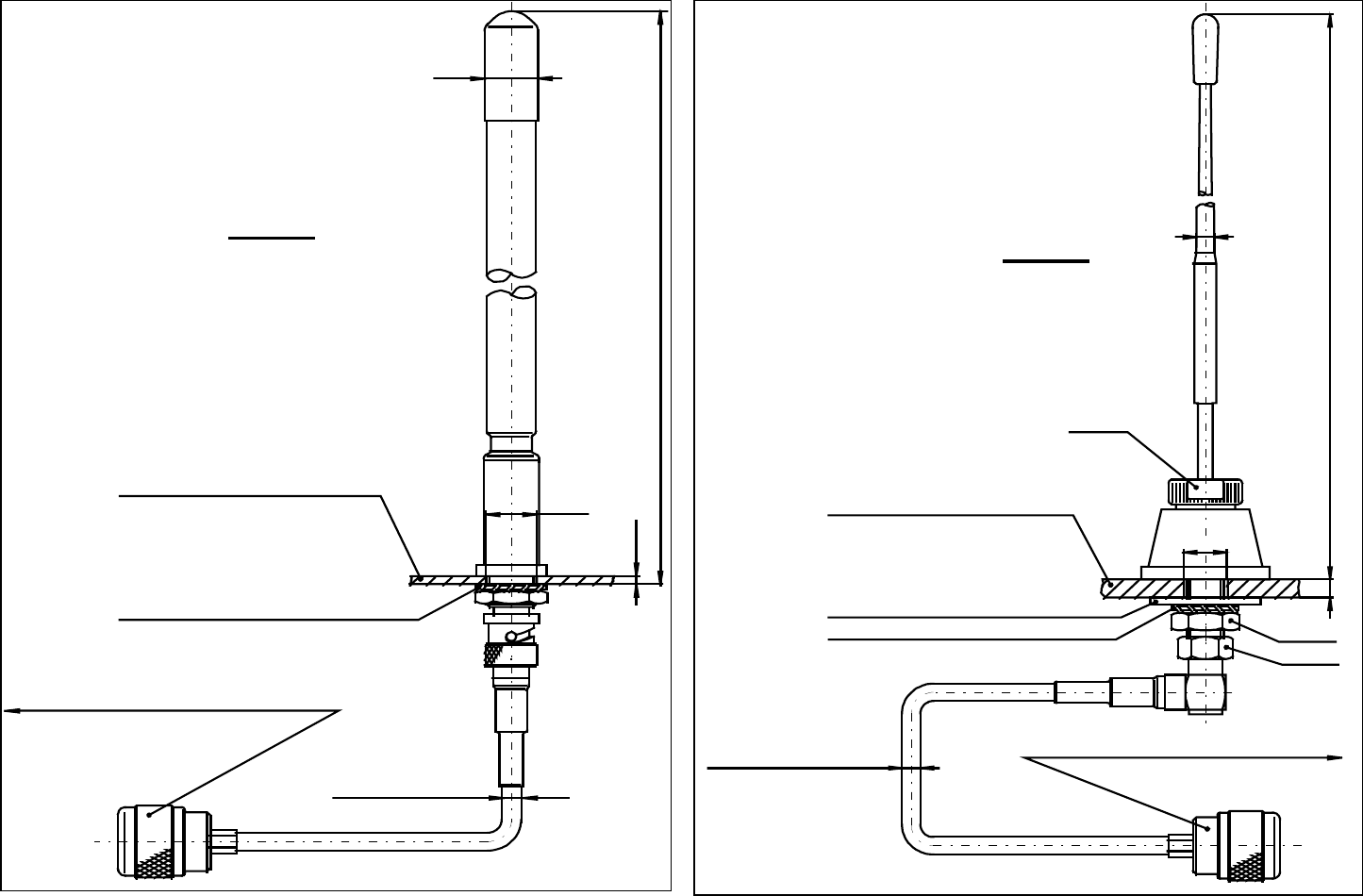
6.2.3 BILZ Antennae
∅
∅
∅
∅ 12
SW 14
∅
∅
∅
∅ 5
SW 17
serrated lock washer
antenna base,
not included
in our supply
cable,
5 meters
washer
∅
∅
∅
∅5
λ
λλ
λ /4
to coaxial socket
of receiver
SW 17
max. 5
HFA 0
all dimensions in mm
∅
∅
∅
∅ 5
cable,
5 meters
∅
∅
∅
∅17
∅
∅
∅
∅ 13
washer
antenna base,
not included
in our supply
to coaxial socket
of receiver
ca. 283
max. 3
HFA 2
all dimensions in mm

BA140.11
Page 16
01/22/2001
7 Maintenance
7.1 Quarterly Maintenance
1. Sight inspection of antenna and its accessories:
a. damages, dirt, moisture
b. screwed connections of the antenna cable and loose plug connections of the remote control indicator.
Protocol:
Date: Name:
1st yearly quarter
2nd yearly quarter.
3rd yearly quarter
4th yearly quarter
2. Quick change adaptors type WESN
Dismantle adaptors’ safety clutches, clean everything and refill with grease Molykote Pate G, readjust
torque according to operating instructions and table BA 102. For cold-forming of threads increase torque val-
ues by 50 % to the values shown in tapping torque tables.
Protocol:
Date: Name:
1st yearly quarter
2nd yearly quarter
3rd yearly quarter
4th yearly quarter

BA140.11
Page 17
01/22/2001
7.2 Semi-annual Maintenance
HFS 3100:
Check of transmitter batteries: All chucks are to be compressed in turn
Fully charged battery Weak battery Empty battery
Chuck compressed:
Yellow ”B.-CHECK” LED flashes
in 1 sec. rhythm.
Chuck compressed:
Yellow ”B.-CHECK” LED flashes
in 1 sec. rhythm.
Chuck compressed:
Yellow ”B.-CHECK” LED doesn’t
light up.
Chuck released:
Yellow ”B.-CHECK” LED flashes
in 1 sec. rhythm till follow-up time
of transmitter has run out, after
which indication ends.
Chuck released:
Yellow ”B.-CHECK” LED flashes
in 1 sec. rhythm till follow-up time
of transmitter has run out, after
which it flashes in .5 sec. rhythm
(battery monitoring alarm).
Chuck released:
Yellow ”B.-CHECK” LED doesn’t
light up.
Remedial actions:
No action required! Remedial actions:
Replace battery! Remedial actions:
Replace battery!
HFS 3000: Remove battery block as per 3.2.2 and test voltage by battery tester: minimum 3.0 V.
Protocol:
Date: Name:
1st half of the year
2nd half of the year

BA140.11
Page 18
01/22/2001
8 Annex
8.1 Frequency Table
D F D FUK USA USA
Channel
No. Frequ.
MHz Channel
No. Frequ.
MHz Channel
No. Frequ.
MHz Channel
No. Frequ.
MHz Channel
No. Frequ.
MHz
0w/o quartz 26 72,000 7 UK 49,820 1 U 49,830 21 U 72,810
1 70,000 27 70,040 8 UK 49,852 2 U 49,860 22 U 72,870
2 70,080 28 70,120 9 UK 49,884 3 U 49,890 23 U 72,930
3 70,160 29 70,200 10 UK 49,916 4 U 49,815 24 U 72,990
4 70,240 30 70,280 11 UK 49,948 5 U 49,845 25 U 72,060
5 70,320 31 70,360 12 UK 49,980 6 U 49,875 26 U 72,120
6 70,400 32 70,440 27 U 72,180
7 70,480 33 70,520 8 U 72,030 28 U 72,240
8 70,560 34 70,600 9 U 72,090 29 U 72,300
9 70,640 35 70,680 10 U 72,150 30 U 72,360
10 70,720 36 70,760 11 U 72,210 31 U 72,420
11 70,800 37 70,840 12 U 72,270 32 U 72,480
12 70,880 38 70,920 13 U 72,330 33 U 72,540
13 70,960 39 71,000 14 U 72,390 34 U 72,600
14 71,040 40 71,080 15 U 72,450 35 U 72,660
15 71,120 41 71,160 16 U 72,510 36 U 72,720
16 71,200 42 71,240 17 U 72,570 37 U 72,780
17 71,280 43 71,320 18 U 72,630 38 U 72,840
18 71,360 44 71,400 19 U 72,690 39 U 72,900
19 71,440 45 71,480 20 U 72,750 40 U 72,960
20 71,520 46 71,560
21 71,600 47 71,640
22 71,680 48 71,720
23 71,760 49 71,800
24 71,840 50 71,880
25 71,920 51 71,960
SDK A
Channel
No. Frequ.
MHz Channel
No. Frequ.
MHz Channel
No. Frequ.
MHz
0w/o quartz 0w/o quartz 0w/o quartz
1 S * 62,000 1 DK 32,275 1 A 40,665
2 S * 62,080 2 DK 32,300 2 A 40,695
3 S * 62,160 3 DK 32,325
4 S * 62,240
5 S * 62,320
6 S * 62,400
7 S 30,270
8 S 30,300
9 S 30,340
* Only for replacement!
For EC-Type Examination see separate file
8.2 Homologations

BA140.10
Otto Bilz Werkzeugfabrik GmbH & Co Telefon (0711) 3 48 01-0
D-73760 Ostfildern (Nellingen) Telefax (0711) 3 48 12 56
HF Tapping Control Unit
System HF 3000
Check-list of HF Tapping Control Unit, system HF 3000
for HF alarm.
The HF Tapping Control Unit supervises tapping during machining process and
indicates arisen faults by alarm signal.
The HF receiver differentiates
between: 1. Procedure alarm due to faults arisen during
tapping operation
2. Battery monitoring alarm due to battery voltage
fallen below limit value
Machine stop due to
procedure alarm
Red LED ALARM at the receiver lights
up, detector ring of the chuck displaced
Cause of malfunction:
Length compensation of chuck com-
pressed due to:
a. released safety clutch by:
− worn out tap
− wrong torque setting in
adaptor
− cored hole too narrow
− cored hole not deep enough
− lack of coolant
b. missing cored hole
c. cored hole not chamfered
d. insufficient initial cutting pressure
by the chuck
Machine stop due to
battery monitoring alarm
Red ARARM and yellow LED BATTERY ALARM
at the receiver light up, detector ring of the chuck
not displaced.
Cause of malfunction:
Battery voltage below limit value.
Such alarm may arise during machining process
as well as during non working time of the machine.
Recognition of the spindle having caused
battery monitoring alarm
The hand-held receiver HFC 70 helps to identify
the chuck having signalized the malfunction.
The chuck emitting alarm signal will be identified
by making contact to the chuck’s transmitting antenna
(yellow ring) by the „HFC 70“ antenna.
ALARM
B.-CHECK
LEVEL
RESET
POWER
HF-RECEIVER

BA140.10
HF-Tapping Control Unit
System HF 3000
Recognition of the spindle having caused
procedure alarm:
Since at procedure alarm the length com-
pensation of the chuck is always being
compressed, the detector ring of the chuck
is inevitably being displaced, thus allowing
to identify the chuck having signalized mal-
function, even at multispindle operation.
After eliminating malfunction push back
detector ring into zero position and cancel
alarm signal by pushing reset button. Now
the machine is ready for operation again.
Malfunction signal is being indicated by
LED bar graph array.
ON
HFC70
antenna
LED bar graph array
Battery monitoring alarm may also be
recognized without the use of HFC 70:
The chucks are to be compressed in
succession. The chuck having signalized
battery monitoring alarm will be recognized
by the fact, that the yellow LED of the
receiver discontinues to give light as long as
the chuck is being compressed.
HF Tool Supervising System
Layout Diagram
transmitter
antenna
detector
ring
Bilz-chuck
type WFLP-HF
or WFL-HF
Bilz-adaptor
type WESN/B
or WES/B
HF-receiver
radio link
detector
ring