user manual

Smart Security
Cushion Display (For CW2)
UM100335
User Guide
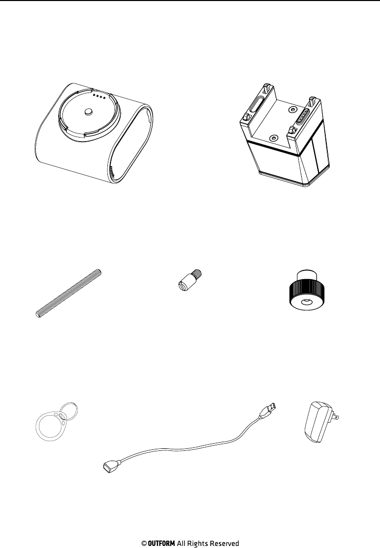
Package Contents Page 1
USB Cable
Cushion Pedestal
Smart Cushion
Screw Nut
Adapter
Threaded Rod
Smart Tag
Small Threaded Screw
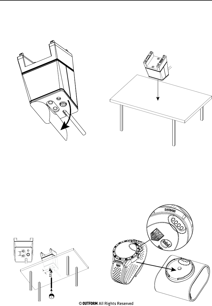
Step 1. Remove the protective film
from the bottom of the pedestal.
Step 2. Firmly press the pedestal onto
a surface for ten seconds to ensure
adhesion.
Step 3. Use the jig provided to
measure and drill the holes in the
bottom of the display table. Insert
the threaded rod and threaded screw
through their respective holes. Turn
them clockwise into the base of the
pedestal. Add a washer onto the
threaded rod then screw the screw nut
onto the rod by hand until the pedestal
is secure.
Step 4. Slide watch onto the smart
cushion, undo the watch strap buckle if
needed and make sure that the spring
pins on the cushion touch the contacts
on the back of the watch face.
Installation Instructions Page 2
Note: For step 2 if needed drill a hole in the table for the power cable to go through.
19mm
19mm
D=7mm
D=6.8mm
Note: Follow step 3 if a stronger connection to the table is needed.
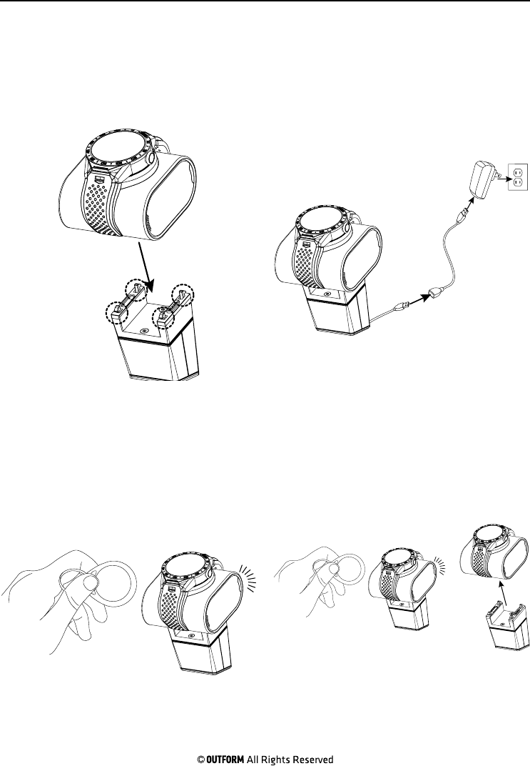
Step 5. Push the smart cushion onto
the four latches on top of the pedestal.
Make sure that the spring pins on the
cushion touch the contacts pedestal.
Step 6. Plug the usb charger into the
power supply cable. Plug the cable into a
nearby power outlet. The watch charges
and the alarms are active.
Step 7. In case the alarm turns on,
hold the tag against the backside of the
pedestal to silence the alarm.
Step 8. Hold the tag against the back
of the pedestal for a few seconds more
to detach the cushion.
Installation Instructions Page 3
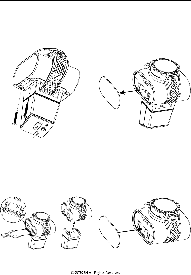
Step 1. Use the screwdriver to remove
the two screws located under the left
side of the cushion.
Step 2. Carefully remove the left
side cushion panel. The panel will be
loosened upon removal of the two
screws.
Step 3. Use the forked key to insert
into the two small slots to detach the
cushion from the pedestal.
Step 4. Replace the left side panel of
the cushion removed in step 2.
Emergency Unlock Page 4
Note: These steps describe how to remove the cushion from the pedestal if the store losses power.
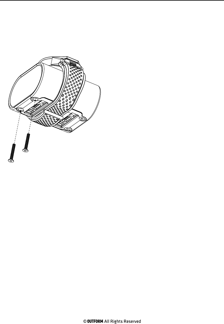
Step 5. Use the screwdriver to install
the two screws removed in step 1
securing the side panel in place.
Emergency Unlock Page 5
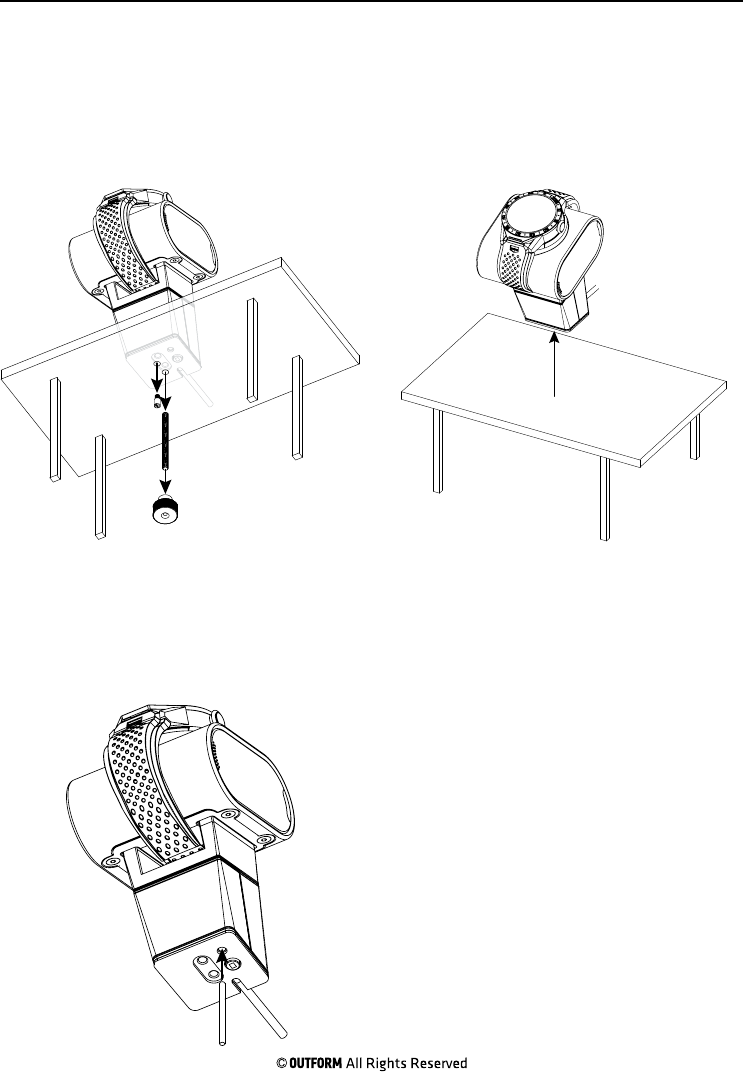
Step 1. Remove the screw nut by hand
and remove the small screw with a
screwdriver from under the display table
and remove the threaded bolt.
Step 2. Carefully lift the pedestal up
from the display table.
Step 3. Use a small rod, insert it into
the bottom of the pedestal press the
reset button and hold for three seconds
to erase the data from the sta and
manager cards.
Reset Switch Page 6
Note: The switch is used to delete all data from the sta and management cards.
Installing the Software and Tags Page 7
The following steps describe how to install the software needed to use the Smart
Tags and how to use the smart tags.
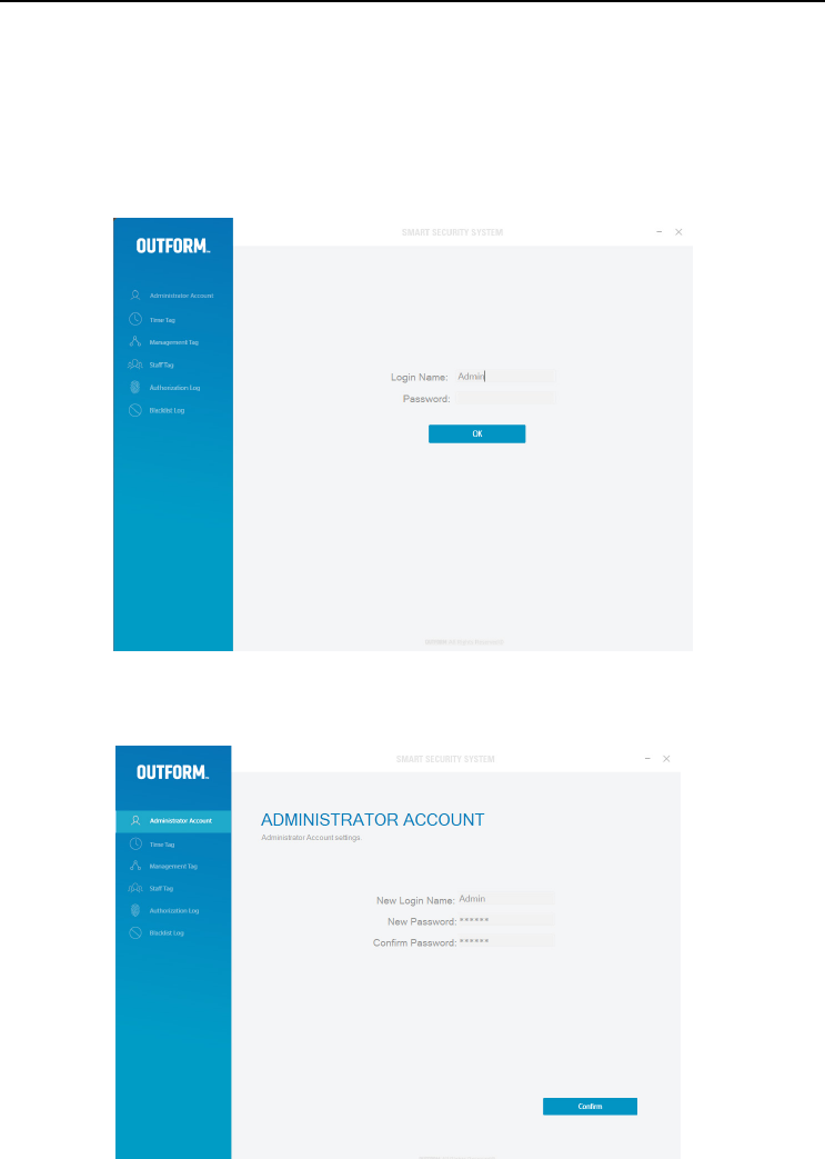
Installing the Software
Install the “smart cushion” software into the windows operated P.C/laptop. Open
the software. The default “Login Name” is Admin, leave the “Password” box blank
and click “OK”.
Administrator Account
A new window will load start changing to a new “Login Name” and new “Password”.
Click “Confirm”. The default new password is 123456.
Installing the Software and Tags Page 8
Note: If for any reason the password is forgotten delete the software from your P.C
or laptop and install the software again. When installation is reinstalled all previous
Tag data is lost. After software installation is complete proceed to re authorize all
Tags.
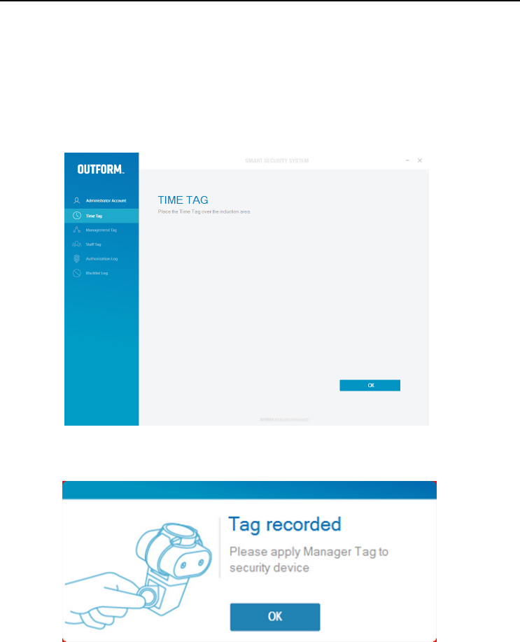
Time Tag
Once you click confirm after changing the user name and password the “Time Tag”
window will open. Place the “Time Tag” over the card reader and click “OK”.
The Timer recorded box will pop up. The “Time Tag” is set successfully. Place
the”Time Tag on the back of the security device and click “OK”.
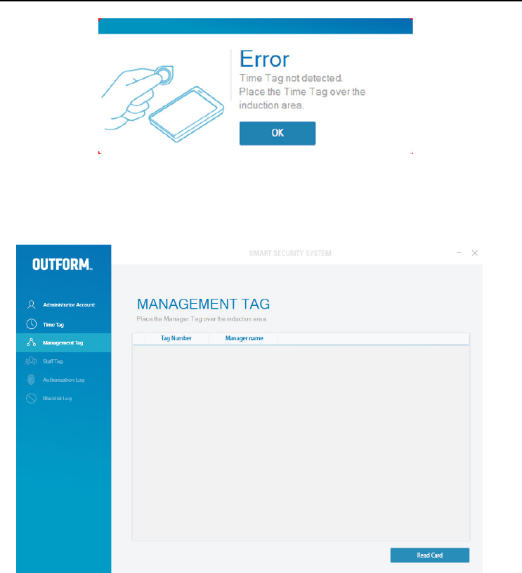
Note: If the following image is shown, there has been an error. The error occurred
because the “Time Tag” has not been detected by the card reader. Place the “Time
Tag” over the card reader again and click “OK”. Refresh the smart cushion with a
“Time Tag” every month/season to stop any errors occurring.
Installing the Software and Tags Page 9
Management Tag
Click on the “Management Tag” tab in the program window. Place the
“Management Tag” on the card reader and click “Read Card”.
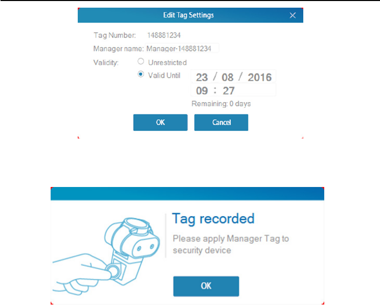
Once “Read Card” has been selected the “Edit Tag settings” box will pop up. Enter
“Manager name”, “Validity” by clicking either “Unrestricted” or “Valid until”. If “Valid
until is selected edit the date and time to suit you and click “OK”to finish.
Note: Make sure that the “Management Card”is placed over the card reader
properly to avoid any errors.
Installing the Software and Tags Page 10
Once this is completed there will be two successive beeps to confirm the Tag has
been set successfully. The “Tag recorded” box will pop up. Apply the “Management
Tag” to the security device. and click “OK”.
When applying the “Management Card” to the security device there will be a short
beeping sound to indicate that the “Management Tag” has been successfully set.
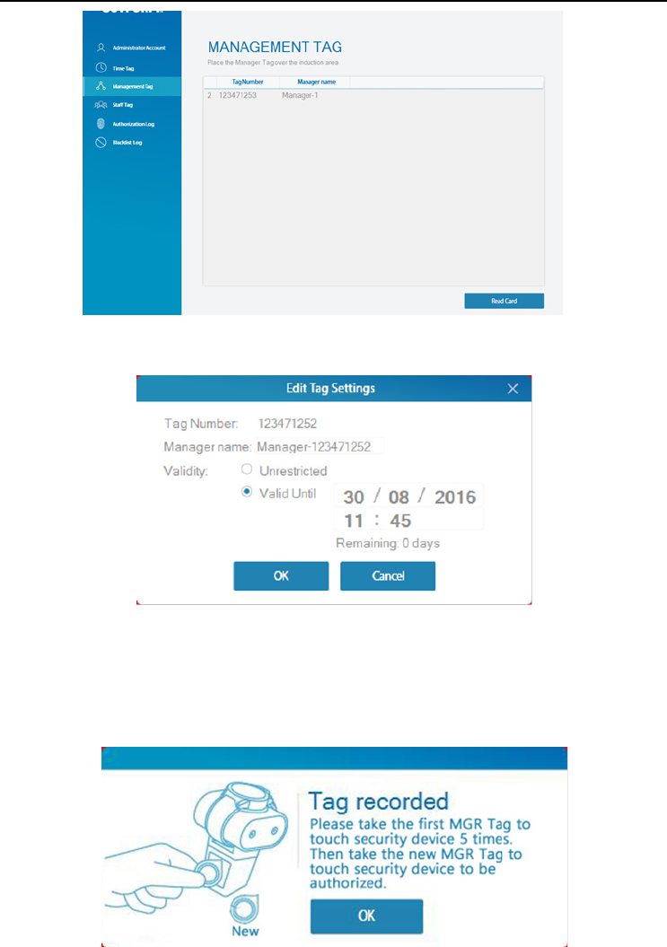
Setting up a second Management Tag
The software allows the user to set up a second “Management Tag” To set up a
second “Management Tag”place the new “Management Tag” on the card reader
and click “Read Card”.
Installing the Software and Tags Page 11
The “Edit Tag Settings” box will pop up. Enter the data just as the first Manager Tag
set up procedure and click “OK”
The “Tag recorded” box will pop up to show the second “Management Tag” has
been successfully set up. Take the first “Management Tag” and apply it to the back
of the security device 5 times, after each successful touch there will be a beeping
sound. Now take the new “Management Tag” and touch it against the security
device once for it to be authorized.
Installing the Software and Tags Page 12
While applying the first “Management Tag” to the security device the LED light will
flash until you apply the new “Management Tag”. The LED will stop flashing once
the second “Management Tag” has been set up successfully.
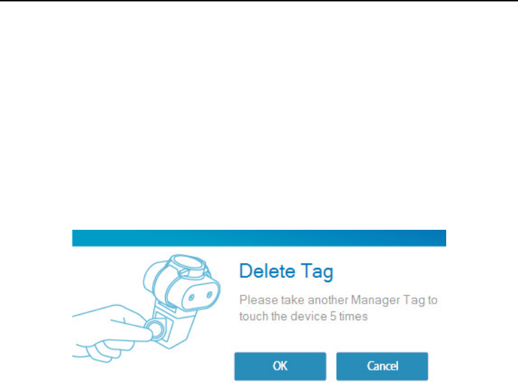
Deleting a Management Tag
If for any reason one of the “Management Tags” is lost, its authority will need to be
deleted from the software in order to access the security device. Place the existing
“Management Tag” against the card reader and click “Read Card” to identify the lost
“Management Tags” unique number. After this information has been realized select
the account with the lost number and click “Delete”. Then take the existing Tag o
of the card reader and touch the existing Tag against the security device 5 times
and Click “OK” to delete.
The lost “Management Tag will now be deleted from the software.
Installing the Software and Tags Page 13
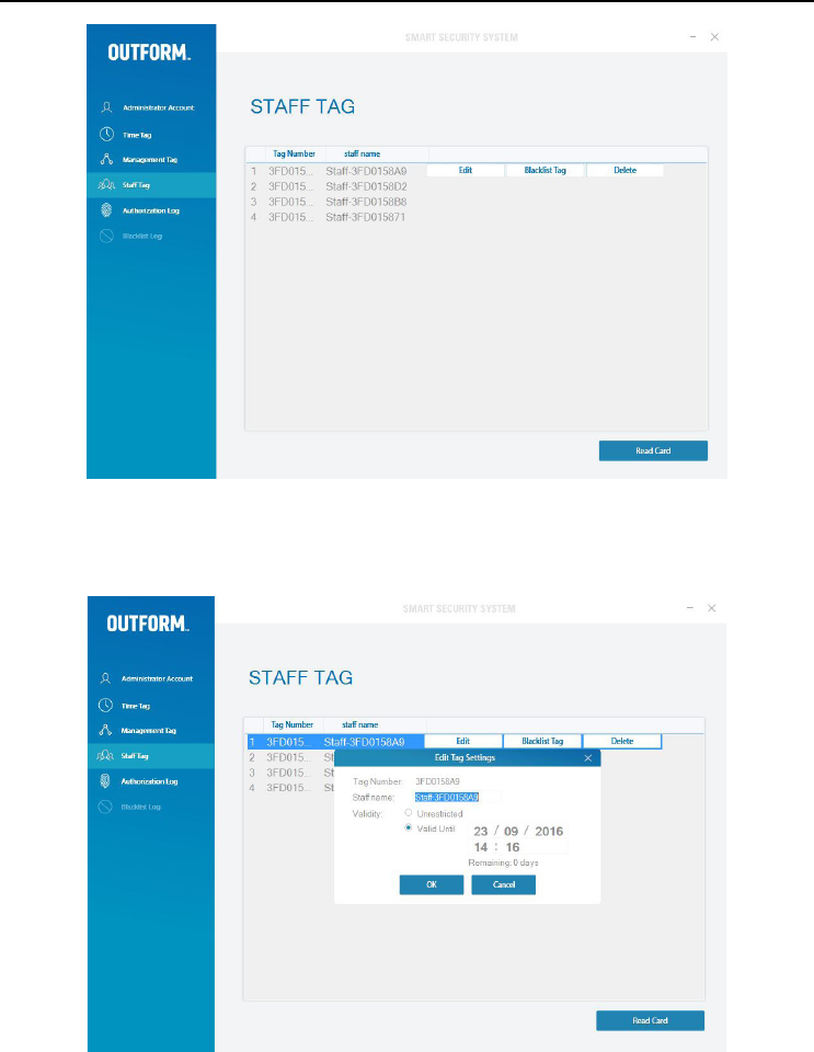
Sta Tag
Place the “Sta Tag” over the card reader and click “Read Card” the “Edit Tag
Settings” box will pop up. Enter the sta name and “Validity” and click “OK”.
Installing the Software and Tags Page 14
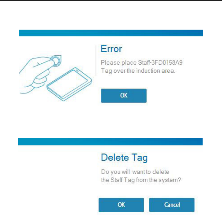
Deleting a Sta Tag
To delete a “Sta Tag from the software first select the desired Tag and click
“Delete” the “Delete Tag” box will pop up. Click “OK” to delete the Tag.
When a “Sta Tag’” is deleted from the software it is still valid and is able to open
the security device. Keep this Tag in a safe location until given to a new employee.
To set up the old Tag for a new employee follow the steps as before.
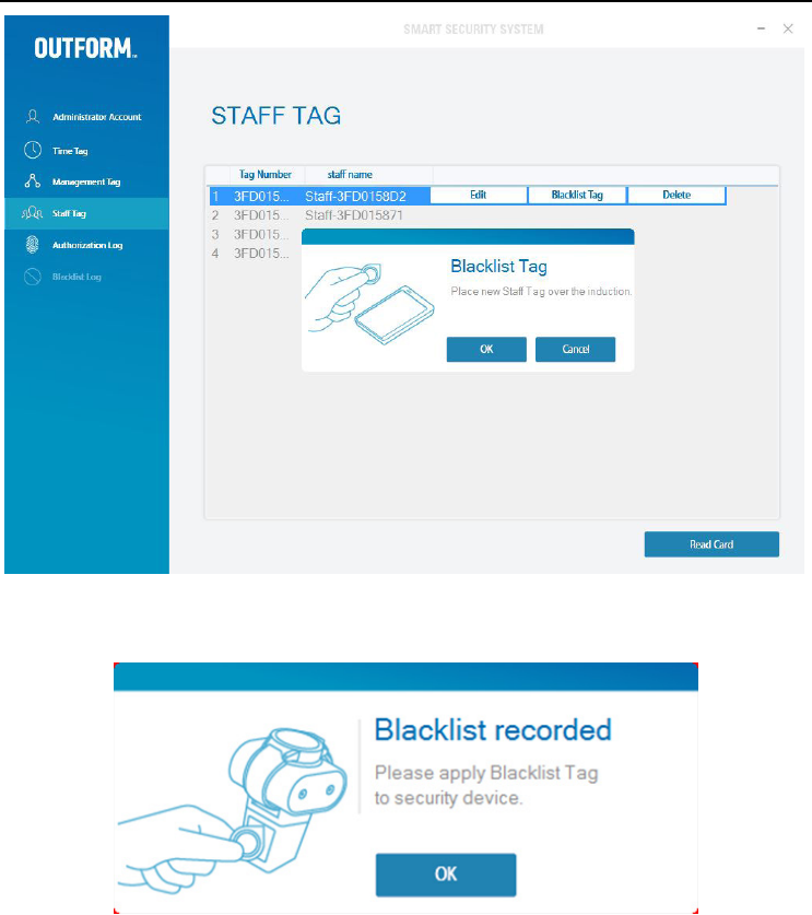
Blacklist Tags
Delete a Sta (Without returning Sta Tag)
Click on the desired Sta name and click on “Blacklist Tag” The “Blacklist Tag” box
will pop up. Place a new “Sta Tag” over the card reader and click “OK”.
If the following Error message appears it means there has been an error. This is
because the “Sta Tag” was not placed properly on the card reader. Place the “Sta
Tag” over the card reader properly and try again.
Installing the Software and Tags Page 15
The Blacklist Tag is successfully set up. Now apply the Blacklisted Tag to the security
device and click “OK”.
Note: Once a Tag has been “Blacklisted” it can not be used again as a “Sta Tag”.

Lost Tags Page 16
Time Tag
If a “Time Tag” is lost then touch one of the “Management Tags” to the security
device 10 times. Then repeat the procedure on page 7.
Management Tag
If a “Management Tag” is lost then touch the other “Management Tag” to the
security device 10 times. Then repeat the procedure on page 8 only this time select
“Validity” in the “Edit Tag Settings” box.
Sta Tag
If a “Sta Tag” is lost then touch one of the “Management Tags” to the security
device 10 times. Then repeat the procedure on page 12.
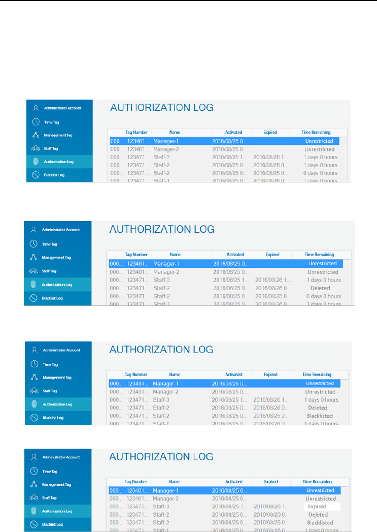
• The “Management Tags” are on top of the list by default.
• “Unrestricted” will show in the ”Time Remaining Column” if “Unrestricted” was
selected while in the “Edit Tag Settings” box.
• “Deleted” will show in the “Time remaining” column if that Tag has been
deleted.
• “Blacklisted” will show in the “Time remaining” column if Tag has been
blacklisted.
• “Expired will show in the “Time remaining” column if Tag is not within validity
Authorization Log Page 17
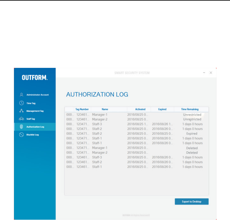
The Authorization Log shows the current Tags information which includes the Tag
number, Tag name, when it was activated, when it expires and the time remaining
until expiration. To see this data click on the “Authorization Log” tab in the software
window.
Authorization Log Page 18
Exporting Authorization Log to Excel
To export go to “Authorization Log” in the software window then click “Export to
Excel” and choose the destination of the save file and click “SAVE”. The excel file can
show one months worth of data at a time.
Note: If the Tag is valid for less than 1 hour the “Time remaining” column will say 1
hour as it is the lowest minimum unit.
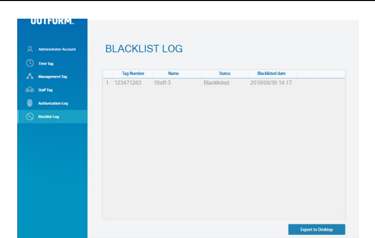
Exporting Blacklist Log To Excel
To export a “Blacklist Log” click on “Blacklist Log” in the program window click on
“Export to Excel” and choose the destination of the save file and click “Save”.
Authorization Log Page 19
FCC Statement:
This device complies with part 15 of the FCC Rules. Operation is subject to the following
two conditions: (1) This device may not cause harmful interference, and (2) this device
must accept any interference received, including interference that may cause undesired
operation.
This equipment has been tested and found to comply with the limits for a Class B digital
device, pursuant to part 15 of the FCC Rules. These limits are designed to provide
reasonable protection against harmful interference in a residential installation. This
equipment generates, uses and can radiate radio frequency energy and, if not installed
and used in accordance with the instructions, may cause harmful interference to radio communications.
However, there is no guarantee that interference will not occur in a
particular installation. If this equipment does cause harmful interference to radio or
television reception, which can be determined by turning the equipment off and on, the
user is encouraged to try to correct the interference by one or more of the following
measures:
—Reorient or relocate the receiving antenna.
—Increase the separation between the equipment and receiver.
—Connect the equipment into an outlet on a circuit different from that to which the
receiver is connected.
—Consult the dealer or an experienced radio/TV technician for help.
Caution: Any changes or modifications not expressly approved by the party responsible
for compliance could void the user's authority to operate the equipment.