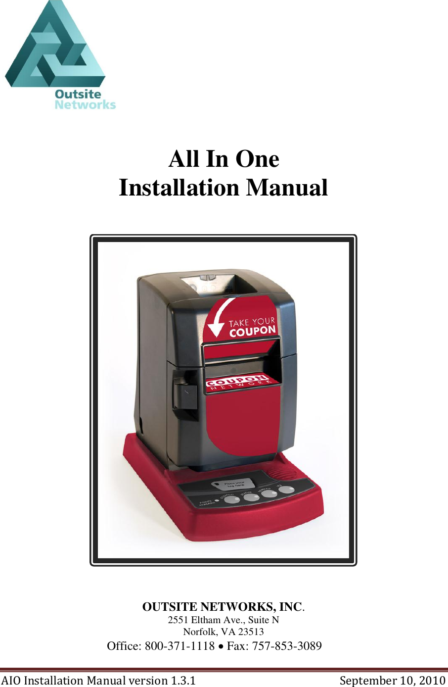
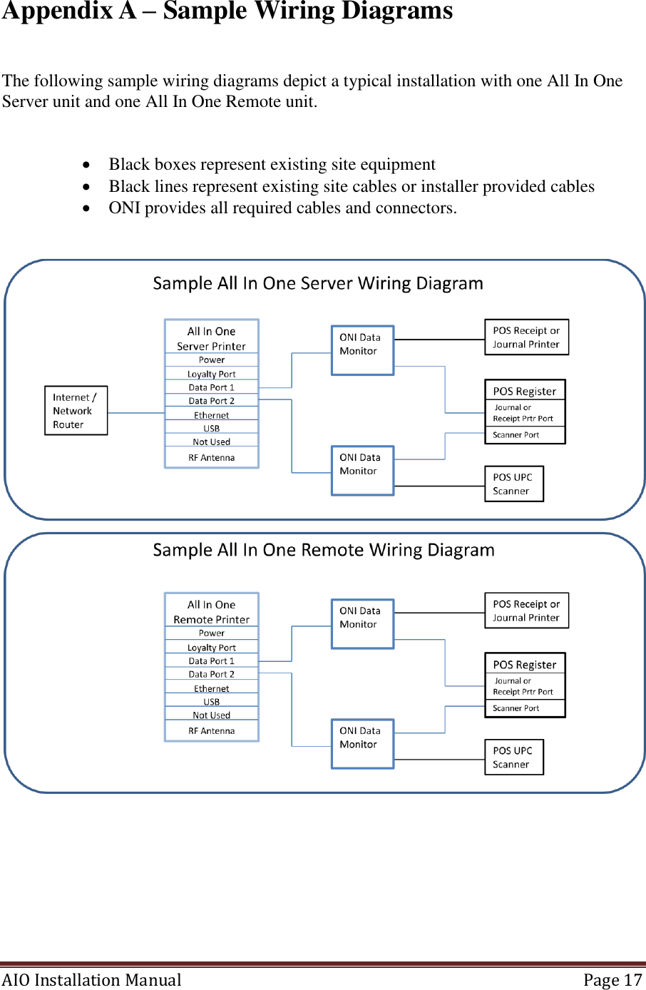
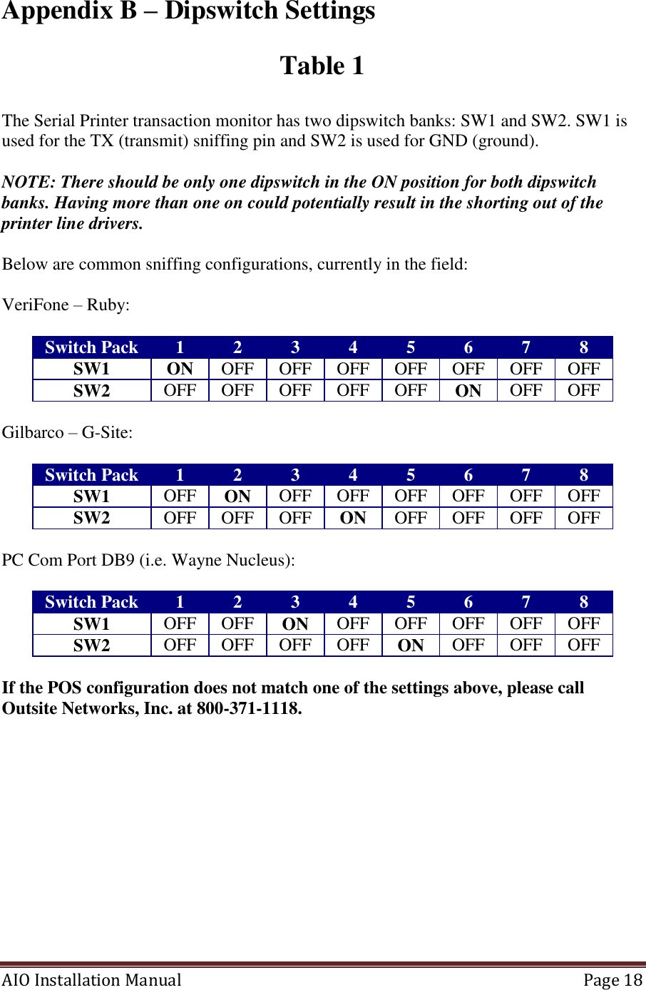
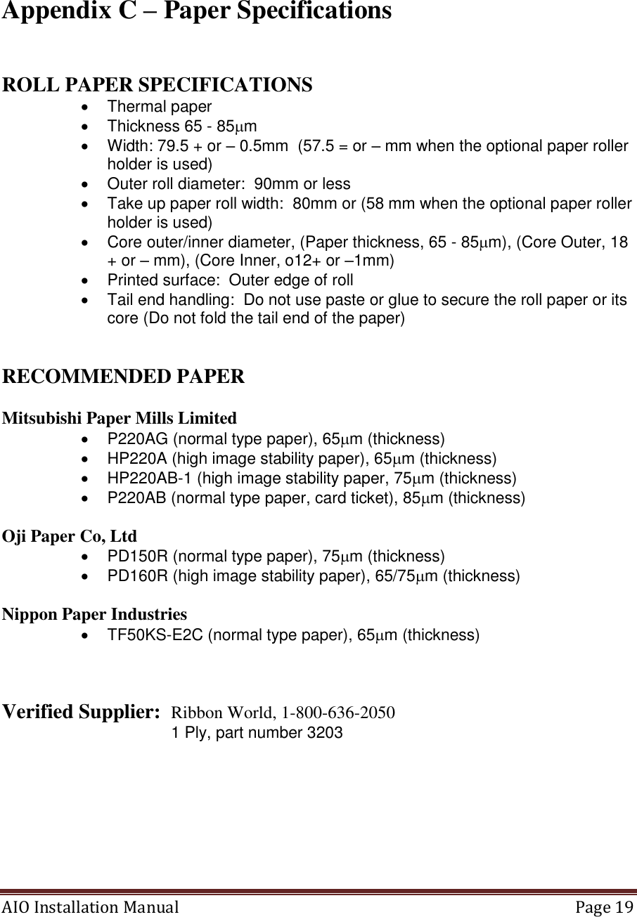
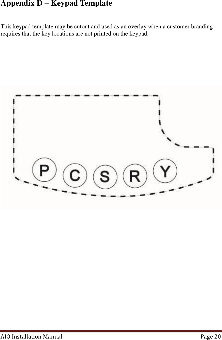
Outsite Networks AIO-2011 All In One Printer User Manual Store Controller Installation Manual

Outsite Networks, Inc. All In One Printer Store Controller Installation Manual

Manual

AIO Installation Manual version 1.3.1    September 10, 2010    All In One Installation Manual      OUTSITE NETWORKS, INC.  2551 Eltham Ave., Suite N Norfolk, VA 23513 Office: 800-371-1118  Fax: 757-853-3089
AIO Installation Manual   Page 2   Upon installation provide this document to the Store Manager                     Copyright  2010 Outsite Networks, ™ Inc.  All rights reserved.  Outsite Networks, Inc created this document.  No part of this publication may be reproduced, stored in a retrieval system, modified, or transmitted in any form or by any means, electronic, mechanical, photocopying, recording or otherwise, without the express, prior written consent of Outsite Networks, Inc.   Note: This equipment has been tested and found to comply with the limits for a Class A digital device, pursuant to part 15 of the FCC Rules. These limits are designed to provide reasonable protection against harmful interference when the equipment is operated in a commercial environment. This equipment generates, uses, and can radiate radio frequency energy and, if not installed and used in accordance with the instruction manual, may cause harmful interference to radio communications. Operation of this equipment in a residential area is likely to cause harmful interference in which case the user will be required to correct the interference at his own expense. Modifications not expressly approved by the manufacturer could void the user's authority to operate the equipment under FCC rules.
AIO Installation Manual   Page 3  Table of Contents  1. Electrical Connection Specifications .......................................................... 4 2. Power Specifications ................................................................................... 4 3. Provided Materials ...................................................................................... 4 4. Optional Materials per configuration requirements .................................... 4 5. Tools Needed .............................................................................................. 5 6. Site Preparation ........................................................................................... 5 7. All In One Printer........................................................................................ 5 8. Installation Procedures ................................................................................ 6 8.1. Connect the Data Monitor Devices ............................................................. 6 8.2. Parallel Port Data Monitor Connection to the POS journal or receipt printer port .............................................................................................. 6 8.3. Serial Port Data Monitor Connection to the POS journal or receipt printer port .......................................................................................................... 7 8.4. Serial Port Data Monitor Connection to the POS journal printer port using DB-9 or DB25 connections ..................................................................... 9 8.5. Serial Port Data Monitor Connection to the POS Barcode Scanner port ... 9 9. Load All In One paper ................................................................................ 9 10. Turn On the All In One ............................................................................. 10 11. Configure the All In One .......................................................................... 10 11.1. Enter All In One Configuration Mode ...................................................... 11 11.2. Configure the Unit Mode .......................................................................... 12 11.3. Configure the Unit ID number .................................................................. 12 11.4. Configure the Unit Group ......................................................................... 13 11.5. Configure the Demo Mode ....................................................................... 13 11.6. Configure the Num Units .......................................................................... 13 11.7. Configure the Internet Connection Settings .............................................. 13 11.8. Configure Static IP settings ...................................................................... 14 11.9. Configure the Site ID number ................................................................... 14 11.10. Configure Servicer Index .......................................................................... 15 11.11. Configure the Service IP Address ............................................................. 15 11.12. Configure the Volume Level .................................................................... 15 12. Connect the All In One to the Internet ...................................................... 16 13. All In One final check-Out ....................................................................... 16 Appendix A – Sample Wiring Diagrams .......................................................................... 17 Appendix B – Dipswitch Settings ..................................................................................... 18 Appendix C – Paper Specifications .................................................................................. 19 Appendix D – Keypad Template ...................................................................................... 20
AIO Installation Manual   Page 4       1. Electrical Connection Specifications  Instructions and Standards 1. Read this guide completely prior to installing the All In One Printer. 2. All Electrical connections must comply with the following:  Equipment must be installed and used in accordance with the National Electrical Code (NEC), and the National Fire Protection Association (NFPA) – Automotive and Marine Service Station Code.  Equipment must be installed in compliance with the instructions set forth in this manual. 3. This manual contains wiring diagrams, drawings, and photographs to assist in the proper installation of the All In One Printer.  Any questions regarding this manual or the proper installation of the All In One Printer should be addressed to Outsite Networks, Inc. at 800-371-1118. 4. RF Radiation Exposure Statement: This equipment complies with FCC RF radiation exposure limits. This equipment should be installed and operated with a minimum distance of 20 cm between the radiator and your body for 2.4-GHz operations. This transmitter must not be co-located or operating in conjunction with any other antenna or transmitter.   2. Power Specifications AC Input    115/230V~, 8/4A, 60/50Hz  3. Provided Materials  All In One Printer  A/C Power Cable  All In One External Power Supply  4.  Optional Materials per configuration requirements  Data Monitor(s)  14’ RJ45 Cat5 Cable(s)  2’ RJ45 Cat5 Cable(s) (used for Serial Printer Data Monitors)  DB-25 printer cable(s) (used for Parallel Printer Data Monitors)
AIO Installation Manual   Page 5   DB-25 to RJ45 Converter (Male and Female used for connecting Serial Printer Data Monitors)  DB-9 to RJ45 Converter (Male and Female used for connecting Serial Printer Data Monitor) 5. Tools Needed  1 – “Jewelers Size” Phillips Screwdriver.  The screw driver may be needed if it is necessary to change dip-switch settings in a Data Monitor.  6. Site Preparation  One 110VAC power outlet within 4’ of the installed All In One Printer  Internet connection jack in close proximity of the All In One Printer configured as the Server unit.   7. All In One Printer   The All In One printer (AIO) prints reward coupons and other consumer related promotional documents. It does not replace the Point of Sale (POS) register receipt printer.  Nor is it installed directly as a configurable / controllable peripheral of the POS.  However, each AIO will be associated with a particular POS device.  The AIO will normally be installed with one or more Data Monitor (DM) devices.  The Data Monitor devices will be configured to capture data from the POS journal or receipt printer port.  Generally capturing transaction data from the journal printer port is more advantageous because it does not require a printed receipt for each transaction.  If the journal port option is not available, then transaction data must be captured from the POS receipt printer port and a receipt must be printed for each transaction.     In addition, a DM will be used to capture product UPC data from the POS Barcode Scanner Port.    Some POS systems provide a Loyalty Port which provides transaction data to external devices such as the All In One printer.  Depending on the particular application, the AIO installation may include a connection to the POS Loyalty Port.  Multiple AIO units may be installed at a retail location.  However, one AIO unit will normally be configured as an AIO Server unit.  The AIO Server will be configured to connect to the internet.  All other AIO units will communicate to the AIO Server in order to send and receive data from the Program Data Center Network.
AIO Installation Manual   Page 6  8. Installation Procedures  Place the AIO unit on the checkout counter adjacent to the POS to which it will be associated.  Ensure that the keypad panel on the front of the All In One Printer and the paper chute are visible and easily accessible by the consumer.  Positioning the All In One Printer in this manner is necessary for proper access and usage by the consumer.  8.1.  Connect the Data Monitor Devices  The AIO unit reads, or captures, transaction information from the POS journal printer or receipt printer port via a Data Monitor (DM).  There are two types of supported Data Monitor devices; a Serial Port Monitor and a Parallel Port Monitor.    Each Data Monitor is installed between the POS and a POS peripheral such as the POS journal printer, receipt printer or the POS Barcode Scanner.    The Serial Port DM requires configuration specific dipswitch settings to appropriately communicate with the AIO unit; the Parallel DM does not.  8.2.  Parallel Port Data Monitor Connection to the POS journal or receipt printer port  NOTE: No transactions should be entered during the connection of any Data Port Monitor device.  Please inform the manager before proceeding.  1. Disconnect the printer cable from the back of the POS. 2. Connect this cable to appropriate port (in most cases this will be the port shown as the Front View) of the Parallel Printer transaction monitor.  3. Connect the provided DB-25 cable from the Parallel DM to the receipt port of the POS. 4. Connect one 14’ Cat5 cable from the Parallel DM RJ-45 port to the DM 1 connection on the back of the AIO.
AIO Installation Manual   Page 7   Parallel DM (Front View)  (Back View)  8.3.  Serial Port Data Monitor Connection to the POS journal or receipt printer port  NOTE: No transactions should be entered during the connection of any Data Monitor device. Please inform the manager before proceeding  The Serial DM must be configured to match the POS/Journal Printer configuration. There are stickers on the Top and Bottom of the Serial DM.  The Top Sticker shown below shows port designations, configuration of SW1, SW2 and the POS Type. The last line shows QA information of tester and date tested.
AIO Installation Manual   Page 8   Serial DM Top Sticker  The Bottom Sticker shows Outsite Networks’ phone number and switch settings when using a G-Site, Ruby POS or Nucleus.   Serial DM Bottom Sticker  Currently the Serial DM supports VeriFone Ruby, Verifone Topaz, Verifone Sapphire, Gilbarco G-Site, Gilabarco Passport, PC Comm Port DB-9 (i.e. Wayne Plus III) or DB-25 (i.e. Wayne Nucleus), Radiant Lighthouse, Radiant Computouch and others. NOTE: See Table 3 for switch settings. 1. Disconnect the journal or receipt printer cable from the back of the POS. This is usually a Cat5 cable with an RJ45 connector. 2. Connect this cable into the port marked RCPT PTR of the Serial DM 3. Connect the provided 2’ Cat5 cable into the printer port of the POS. 4. The other end of the 2’ Cat5 cable connects to the port marked POS on the Serial DM. 5. Connect one provided 14’ Cat5 cable from the port marked STR CONT of the Serial DM to the DM 1 connection on the back of the AIO.
AIO Installation Manual   Page 9   8.4.  Serial Port Data Monitor Connection to the POS journal printer port using DB-9 or DB25 connections  The instructions below are for installation of the Serial DM using a DB-9 converter or DB-25 converter. ONI will provide one DB-9 Male and one DB-9 Female converter (or one DB-25 Male and one DB-25 Female) pending on the printer connection (the steps below use a DB-9). 1. Disconnect the journal or receipt printer cable from the back of the POS. The printer will be connected to the serial port of the POS. This is usually a male port. 2. Connect this cable into to a DB-9 Male RJ45 converter. Once connected, take one provided 14’ Cat5 cable and connect it to the converter. 3. Connect the other end of the 14’ Cat5 cable to the POS port of the Serial DM. 4. Connect the provided 2’ Cat5 cable into a DB-9 Female RF45 converter. Connect this into the printer port of the POS. 5. The other end of the 2’ Cat5 cable connects to the RCPT port of the Serial DM. 6. Connect one provided 14’ Cat5 cable from STR CONT port of the Serial DM to the DM 1 connection on the back of the AIO.  8.5.  Serial Port Data Monitor Connection to the POS Barcode Scanner port  1. Disconnect the Barcode Scanner cable from the back of the POS. This is usually a Cat5 cable with an RJ45 connector. Connect this cable into the port marked RCPT PTR of the Serial DM. 2. Connect the provided 2’ Cat5 cable into the scanner port of the POS. 3. The other end of the 2’ Cat5 cable connects to the port marked POS on the Serial DM. 4. Connect one provided 14’ Cat5 Cable from the port marked STR CONT of the Serial DM to the DM 2 connection on the back of the AIO.   9. Load All In One paper  The All In One printer uses thermal paper.  The paper specifications are provided in Appendix C.  A roll of paper is provided in the box with every AIO unit.    Open the paper compartment by pressing down on the compartment latch button located on the left side of the paper compartment door.   Insert the paper roll with the paper feeding over the top of the roll.
AIO Installation Manual   Page 10  Note:  There is an illustration on the inside of the paper compartment door showing how the paper should be loaded.  10. Turn On the All In One   The AIO unit does not require a dedicated/isolated ground outlet.  However, the electrical service should be suitable for the installation of computer based electronic equipment.  The All In One unit consist of two major components; the printer and the electronics base. Thus turning on the AIO requires turning on both the printer and the electronics base.    Therefore turning on the AIO unit is a three step process:    1. Turn the AIO printer power switch to the on position.  The printer power (on/off) switch is located on the printer’s right side as you are facing it.  This power switch only controls power to the printer.  It does not provide power to the All In One electronics in the base of the unit. 2. Connect the provided AIO power supply to the AIO Power port on the back connection panel of the unit. 3. Connect the AIO power supply to the electrical outlet.   Note:  Turning the power switch on the side of the printer on and off does not cycle power to the AIO electronics base.  Cycling power to the electronics base requires disconnecting the AIO power supply from the electrical out.  11. Configure the All In One   The AIO has several configuration items which may require setting.  Setting these item values is accomplished by placing the AIO unit into the “Configuration Mode” using the keypad at the unit’s base.    The keypad consists of 5 keys each of which has a corresponding L.E.D. light.  Depending on the on the customer branding, some of the keys may not be printed on the keypad.  However, the five L.E.D. lights should always be visible.    Appendix D provides a keypad template which may be cutout and used as an overlay if the keys are not printed.  Starting from left to right, this manual refers to the keys with the following letters: P, C, S, R, Y.
AIO Installation Manual   Page 11  11.1. Enter All In One Configuration Mode  To enter the Configuration Mode, simultaneously press and hold both the P and C keys for 2 seconds and then release both.  The AIO unit will then enter the Configuration Mode and print the current “Basic Configuration” values as seen below:        The letters at the beginning of each item represent the keyboard keys.  To change one of the item values, press the 1st key then the 2nd key to select the item.  In this manual we will refer to these 1st and 2nd key combinations as #/#; for example C/C.   After pressing the indicated keys, additional status and instruction messages will print.   Using the example above to change the Volume level, press P/R or the “P” key followed by the “R” key. Then follow the printed directions.  To exit the Configuration Mode press P/P or the “P” key followed by the “P” key again.
AIO Installation Manual   Page 12   Note:  Upon exiting the Configuration Mode after making a change, the AIO will always recycle and print the Basic Configuration.  If no operational configuration change was made, the AIO will not reset and the Basic Configuration will not print.     11.2. Configure the Unit Mode  The All In One printer operates in one of two available Unit Modes; Server or Remote.  The Server mode allows the AIO to connect to the Internet and act as an internet access server for other AIO units which operate as Remote units.  AIO units operating in the Remote mode do not connect directly to the Internet and must connect to an AIO operating in the Server Mode.  Only one AIO unit should be configured to operate in the Server mode per site.  That unit will be referred to in this manual as the AIO Server.  The Unit Mode values are:  Server Mode  = “1” Remote Mode = “2”   After entering the Configuration Mode, set the Unit Mode item value, pressing the “C” key followed by the “C” key again.  And then follow the printed directions.  11.3. Configure the Unit ID number  Configuration of the AIO requires setting the printer’s Unit ID #.  The AIO server unit must always be configured as Unit ID number “1”.   If more than one AIO unit is installed at the site, the additional units must be installed as Unit ID number “2” and up.        To set the Unit ID item, press C/S or the “C” Key followed by the “S” key and then follow the printed directions.  Note: By default setting the Unit Mode to “1” will set the Unit ID number to “1”.  Setting the Unit Mode to “2” will set the Unit ID to “2”.  If more than one AIO unit is set to the Remote Mode then the Unit ID must be manually incremented.  For example, if there are 3 AIO units at a site, the 2nd AIO set to Unit Mode “2” would need to be set to Unit ID number “3”.
AIO Installation Manual   Page 13  11.4. Configure the Unit Group  The Unit Group item must be set the same for all wireless ONI loyalty devices at the site including all of the AIO unit units and the Touch Point units installed on any dispensers.    The Unit Group defines the wireless channel that all of the devices will use to communicate with one another.  You may think of the Unit Group as a channel on a Citizen Band (CB) radio.  Because the wireless range of the equipment is up to one mile, the Unit Group number may need to be changed in order not to conflict with other sites using wireless ONI loyalty equipment.  Consult with the ONI service group at 1-800-371-1118 to determine if there may be other conflicting sites in the area.  To set the Unit Group item, press C/R or the “C” Key followed by the “R” key and then follow the printed directions.  11.5. Configure the Demo Mode  The Demo Mode item allows the unit to be placed in one of several demonstration modes.  This value should be left at “0”.  11.6. Configure the Num Units  The “Num Units” item must be set for the AIO Server unit.  The Number of Units value should equal the total number of AIO units installed at the site including the server unit.    To set the Num Units item, press C/P or the “C” Key followed by the “P” key and then follow the printed directions. 11.7. Configure the Internet Connection Settings  One All In Printer at each location must be configured with the Unit Mode set to “1” or Server mode.  And that unit must be configured to access the Internet. The AIO unit can be configured to use either Dynamic Host Configuration Protocol (DHCP) or a fixed Internet Protocol (IP) address.  When an AIO unit is configured for Unit Mode “1”, the Use DHCP configuration item will automatically be set to “1” which means it will use DHCP.  It will by default be ready to connect to the Internet using DHCP.  If DHCP is appropriate for the Internet service at the site no further Internet options need to be configured.
AIO Installation Manual   Page 14  The Use DHCP values are:  Do not use DHCP  = “0” Use DHCP    = “1”  To set the Use DHCP item value to “0” meaning do not use DHCP”, press S/C or the “S” key followed by the “C” key and then follow the printed directions.  11.8. Configure Static IP settings  If the Internet service at the site requires a static IP address and the Use DHCP item has been configured to “0”.  Then it will be necessary to set the IP address, Subnet Mask, Gateway and DNS values per the Internet Service provider’s requirements.  Press the appropriate Menu keys (#/#) to select the item and then follow the printed instructions.   (Use this table as a place to write the required configuration information) Configuration Menu Keys Internet Address Menu Item   Part 1    Part 2   Part 3   Part 4 # # #    # # #    # # #     # # # S/S IP Address 1 ______ ______ ______ ______ S/R Subnet Mask  ______ ______ ______ ______ R/C Default Gateway Index  R/S Default Gateway 1 ______ ______ ______ ______ R/R Default Gateway 2 ______ ______ ______ ______ R/Y Default Gateway 3 ______ ______ ______ ______ Y/C DNS Server Index  Y/S DNS Server 1 ______ ______ ______ ______ Y/R DNS Server 2 ______ ______ ______ ______ Y/Y DNS Server 3 ______ ______ ______ ______  11.9. Configure the Site ID number  All In One units set to Mode “1” or Server Mode, must have the Site ID number configured.
AIO Installation Manual   Page 15   The unique Site ID number identifies each server and the location where it is installed.  The Site ID consists of the following characters:   ZZZZZTTTT1    Where ZZZZZ   = the Site’s Zip Code  Where TTTT   = the last four digits of the sites main voice telephone line  Where 1   = the number 1  For example if the site’s Zip Code is 12345 and the main voice telephone number is 757-853-3000, the Site ID would be 1234530001.    (Use this table as a place to write the required configuration information) ITEM VALUE ZipCode: (ZZZZZ)  Last four digits of the main voice telephone number: (TTTT)  SiteID: (ZZZZZTTTT1)   To set the Unit ID item, press S/Y or the “S” Key followed by the “Y” key and then follow the printed directions.  Once all of the digits of the Site ID have been entered, you may exit the menu by pressing P/P.   11.10.  Configure Servicer Index  The Servicer Index item is used to connect with a specific ONI service technician during remote configuration or diagnostics.  This value should only be changed or set under the supervision of an ONI service technician.  11.11.  Configure the Service IP Address  The Service IP Address item is used to connect with ONI service during remote configuration or diagnostics.  This value should only be changed or set under the supervision of an ONI service technician.  11.12.  Configure the Volume Level
AIO Installation Manual   Page 16  Use the Volume Level item to increase the audio volume level.  By default the AIO volume level will be set to “4”.  The Volume Level range is “0” to “9”.   To change the Volume level, press P/R or the “P” key followed by the “R” key again. Then follow the printed directions.   12. Connect the All In One to the Internet  The AIO Server Unit requires an Internet connection to function properly.  After configuring the AIO Server unit per the Section 11 of this document, use the AIO RJ45 Ethernet port on the back of the unit to connect the server unit to the Internet.   13. All In One final check-Out  After all of the AIO units to be installed are configured and the server unit is connected to the Internet, contact the ONI Service department at 1-800-371-1118 to complete the AIO server configuration remotely.  The ONI Service Department is available to remotely configure units between 8:00 a.m. EST and 6:30 p.m. EST, Monday through Friday.  When contacting the ONI Service department have the Server Site ID number, Site Name, address and telephone number available.  The Service Technician will need this information.
AIO Installation Manual   Page 17  Appendix A – Sample Wiring Diagrams   The following sample wiring diagrams depict a typical installation with one All In One Server unit and one All In One Remote unit.     Black boxes represent existing site equipment  Black lines represent existing site cables or installer provided cables  ONI provides all required cables and connectors.
AIO Installation Manual   Page 18  Appendix B – Dipswitch Settings  Table 1   The Serial Printer transaction monitor has two dipswitch banks: SW1 and SW2. SW1 is used for the TX (transmit) sniffing pin and SW2 is used for GND (ground).  NOTE: There should be only one dipswitch in the ON position for both dipswitch banks. Having more than one on could potentially result in the shorting out of the printer line drivers.  Below are common sniffing configurations, currently in the field:  VeriFone – Ruby:  Switch Pack 1 2 3 4 5 6 7 8 SW1 ON OFF OFF OFF OFF OFF OFF OFF SW2 OFF OFF OFF OFF OFF ON OFF OFF  Gilbarco – G-Site:  Switch Pack 1 2 3 4 5 6 7 8 SW1 OFF ON OFF OFF OFF OFF OFF OFF SW2 OFF OFF OFF ON OFF OFF OFF OFF  PC Com Port DB9 (i.e. Wayne Nucleus):  Switch Pack 1 2 3 4 5 6 7 8 SW1 OFF OFF ON OFF OFF OFF OFF OFF SW2 OFF OFF OFF OFF ON OFF OFF OFF  If the POS configuration does not match one of the settings above, please call Outsite Networks, Inc. at 800-371-1118.
AIO Installation Manual   Page 19    Appendix C – Paper Specifications   ROLL PAPER SPECIFICATIONS   Thermal paper   Thickness 65 - 85m   Width: 79.5 + or – 0.5mm  (57.5 = or – mm when the optional paper roller holder is used)   Outer roll diameter:  90mm or less   Take up paper roll width:  80mm or (58 mm when the optional paper roller holder is used)   Core outer/inner diameter, (Paper thickness, 65 - 85m), (Core Outer, 18 + or – mm), (Core Inner, o12+ or –1mm)   Printed surface:  Outer edge of roll   Tail end handling:  Do not use paste or glue to secure the roll paper or its core (Do not fold the tail end of the paper)   RECOMMENDED PAPER  Mitsubishi Paper Mills Limited   P220AG (normal type paper), 65m (thickness)   HP220A (high image stability paper), 65m (thickness)   HP220AB-1 (high image stability paper, 75m (thickness)   P220AB (normal type paper, card ticket), 85m (thickness)  Oji Paper Co, Ltd   PD150R (normal type paper), 75m (thickness)  PD160R (high image stability paper), 65/75m (thickness)  Nippon Paper Industries   TF50KS-E2C (normal type paper), 65m (thickness)    Verified Supplier:  Ribbon World, 1-800-636-2050                             1 Ply, part number 3203
AIO Installation Manual   Page 20  Appendix D – Keypad Template   This keypad template may be cutout and used as an overlay when a customer branding requires that the key locations are not printed on the keypad.

Navigation menu