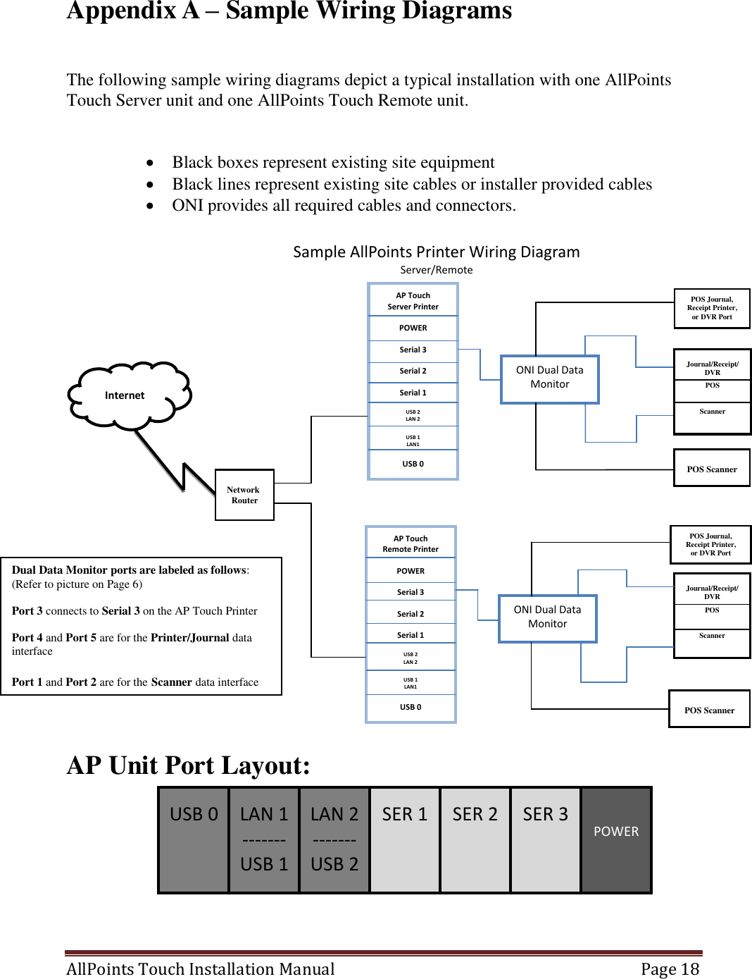
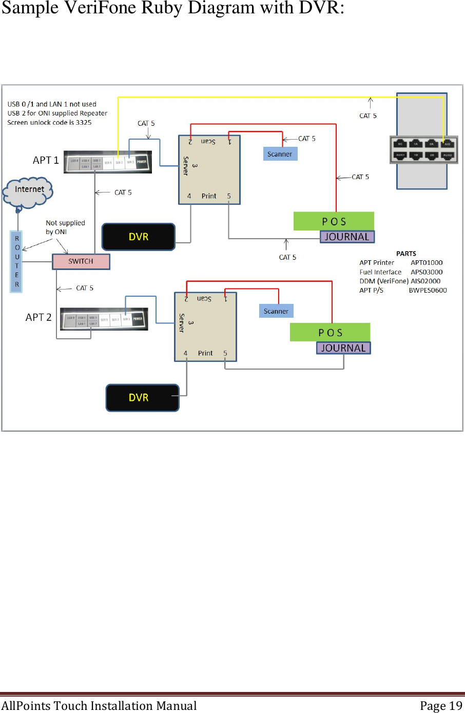
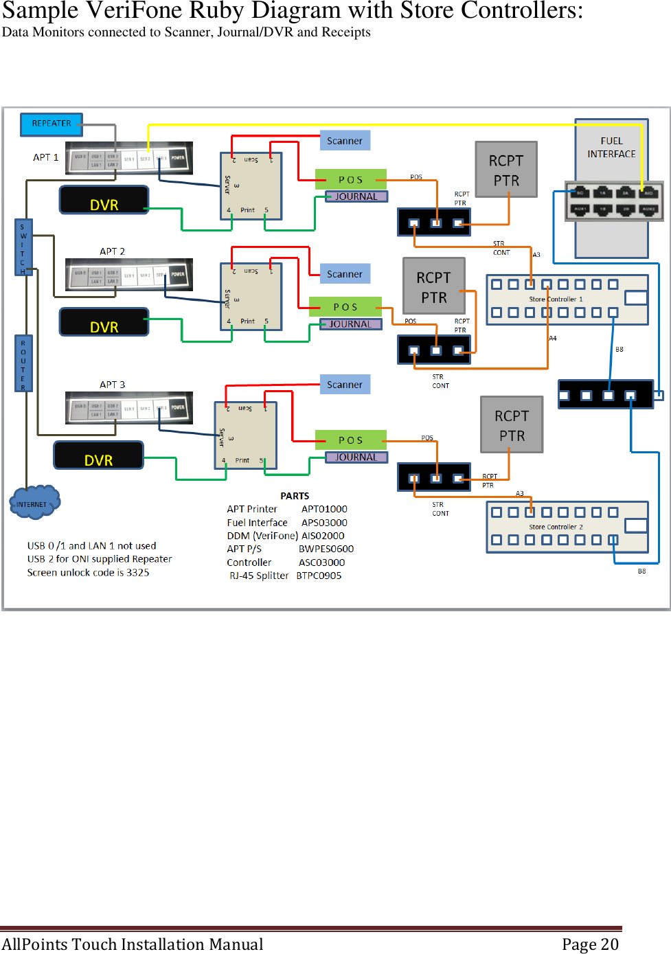
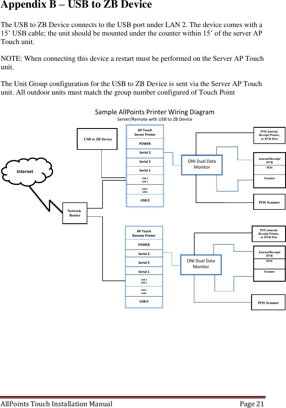
Outsite Networks APT-2014 AllPoints Touch Printer (APT) User Manual

Outsite Networks, Inc. AllPoints Touch Printer (APT)

User Manual

Rhein Tech Laboratories, Inc.  Client: Outsite Networks, Inc. 360 Herndon Parkway  Model: APT Suite 1400  Standards: FCC 15.225/IC RSS-210 Herndon, VA 20170  ID’s: U2C-APT-2014/6944A-APT http://www.rheintech.com  Report #: 2014053    Page 30 of 41  Appendix J:  Manual  Please refer to the following pages.
 AllPoints Touch Installation Manual 2.1  July 2, 2013      AllPoints™ Touch Printer Installation Manual  (Touch Unit for VeriFone Ruby or Topaz and TDL NCR RealPOS 7402 Models)      OUTSITE NETWORKS, INC.  2551 Eltham Ave., Suite N Norfolk, VA 23513 Office: 800-371-1118  Fax: 757-853-3089
 AllPoints Touch Installation Manual   Page 2   Upon installation provide this document to the Store Manager         Copyright  2012 Outsite Networks, ™ Inc.  All rights reserved.  Outsite Networks, Inc. created this document.  No part of this publication may be reproduced, stored in a retrieval system, modified, or transmitted in any form or by any means, electronic, mechanical, photocopying, recording or otherwise, without the express, prior written consent of Outsite Networks, Inc.       Note: This equipment has been tested and found to comply with the limits for a Class A digital device, pursuant to part 15 of the FCC Rules. These limits are designed to provide reasonable protection against harmful interference when the equipment is operated in a commercial  environment.  This  equipment  generates,  uses,  and  can  radiate  radio frequency energy and, if not installed and used in accordance with the instruction manual, may cause harmful interference to radio communications. Operation of this equipment in a residential area is likely to cause harmful interference in which case the user will be required to correct interference at their expense. Modifications not expressly approved by the  manufacturer  could  void  the  user's  authority  to  operate  the  equipment  under  FCC rules.  Changes or modifications not expressly approved by the manufacturer could void the user’s authority to operate the equipment.     This device complies with Industry Canada license-exempt RSS standard(s). Operation is subject to the following two conditions: (1) this device may not cause interference, and (2) this device must accept any interference, including interference that may cause undesired operation of the device.   Le présent appareil est conforme aux CNR d'Industrie Canada applicables aux appareils radio exempts de licence. L'exploitation est autorisée aux deux conditions suivantes : (1) l'appareil ne doit pas produire de brouillage, et (2) l'utilisateur de l'appareil doit accepter tout brouillage radioélectrique subi, même si le brouillage est susceptible d'en compromettre le fonctionnement.
 AllPoints Touch Installation Manual   Page 3
 AllPoints Touch Installation Manual   Page 4  Table of Contents  1. Electrical Connection Specifications .......................................................... 5 2. Power Specifications ................................................................................... 5 3. Environmental Conditions .......................................................................... 5 4. Provided Materials ...................................................................................... 5 5. Optional Materials per configuration requirements .................................... 6 6. Tools Needed .............................................................................................. 6 7. Site Preparation ........................................................................................... 6 8. AllPoints Touch Printer .............................................................................. 6 9. Installation Procedures ................................................................................ 7 8.1 VeriFone Ruby/Verifone Topaz DDM Instructions ................................... 8 8.2 TDL NCR RealPOS 7402 Instructions ....................................................... 8 8. Make Network Connections ....................................................................... 9 9. Load AllPoints Touch paper ....................................................................... 9 10. Powering On the AllPoints Touch .............................................................. 9 11. Configure the AllPoints Touch ................................................................. 10 11.1. EZ-Install Application .............................................................................. 10 11.2. Manual configuration ................................................................................ 10 11.2.1. Enter AllPoints Touch Configuration Mode ............................................. 10 11.2.2. Configure the Unit Mode .......................................................................... 13 11.2.3. Configure the Unit ID number .................................................................. 13 11.2.4. Configure the Unit Group ......................................................................... 14 11.2.5. Configure the Demo Mode ....................................................................... 14 11.2.6. Configure the Num Units .......................................................................... 14 11.2.7. Configure the Internet Connection Settings .............................................. 14 11.2.8. Configure Static IP settings ...................................................................... 15 11.2.9. Configure the Site ID number ................................................................... 16 11.2.10. Configure Servicer Index .......................................................................... 16 11.2.11. Configure the Service IP Address ............................................................. 16 11.2.12. Configure the Volume Level .................................................................... 17 12. Connect the AllPoints Touch to the Internet ............................................. 17 13. AllPoints Touch final check-Out .............................................................. 17 Appendix A – Sample Wiring Diagrams .......................................................................... 18 Appendix B – USB to ZB Device ..................................................................................... 21 Appendix C – Fuel Interface Box ..................................................................................... 22 Appendix D – Paper Specifications .................................................................................. 23
 AllPoints Touch Installation Manual   Page 5      1. Electrical Connection Specifications  Instructions and Standards 1. Read this guide completely prior to installing the AllPoints Touch Printer. 2. All Electrical connections must comply with the following:  Equipment must be installed and used in accordance with the National Electrical Code (NEC), and the National Fire Protection Association (NFPA) – Automotive and Marine Service Station Code.  Equipment must be installed in compliance with the instructions set forth in this manual. 3. This manual contains wiring diagrams, drawings, and photographs to assist in the proper installation of the AllPoints Touch Printer.  Any questions regarding this manual or the proper installation of the AllPoints Touch Printer should be addressed to Outsite Networks, Inc. at 800-371-1118.  2. Power Specifications  AC Input    100-240V~, 60/50Hz, 1.5 (1.5A)  3. Environmental Conditions  Operating. Temperature: 5°C to 45°C Humidity: 10% to 90% RH (without condensation)   Transport/storage (except for paper)  Temperature: -20°C to 60°C  Humidity:  10% to 90% RH (without condensation)  4. Provided Materials   AllPoints Touch Printer(s)  A/C Power Cable  AllPoints Touch External Power Supply
 AllPoints Touch Installation Manual   Page 6  5. Optional Materials per configuration requirements   Dual Data Monitor(s)  14’ RJ45 Cat5 Cable(s)  2’ RJ45 Cat5 Cable(s) (used for Data Monitors)  DB-25 to RJ45 Converter (Male and Female used for connecting Serial Printer or Scanner Dual Data Monitors)  DB-9 to RJ45 Converter (Male and Female used for connecting Serial Printer Dual Data Monitor)  6. Tools Needed  None needed for AP Touch unit using Dual Data Monitor (DDM) or All Points Interface (API). 7. Site Preparation   One 110VAC power outlet within 4’ of each installed AllPoints Touch Printer  LAN connection jack in close proximity of each AllPoints Touch Printer to be installed.   8. AllPoints Touch Printer   The AllPoints Touch printer (AP Touch) prints reward coupons and other consumer related promotional documents. It does not replace the Point of Sale (POS) register receipt printer.  Nor is it installed directly as a configurable / controllable peripheral of the POS.  However, each AP Touch unit is associated with a particular POS device.  The AP Touch will normally be installed with one Dual Data Monitor (DDM) device.  The Dual Data Monitor device is configured to capture data from the POS journal or receipt printer port.  Generally capturing transaction data from the journal printer port is more advantageous because it does not require a printed receipt for each transaction.  If the journal port option is not available, then transaction data must be captured from the POS receipt printer port and a receipt must be printed for each transaction.     In addition, a DDM/API  will be used to capture product UPC data from the POS Barcode Scanner Port.
 AllPoints Touch Installation Manual   Page 7   Some POS systems provide a Loyalty Port which provides transaction data to external devices such as the AllPoints Touch printer.  Depending on the particular application, the AP Touch installation may include a connection to the POS Loyalty Port.  Multiple AP Touch units may be installed at a retail location.  However, one AP Touch unit will normally be configured as an AP Touch Server unit.  The AP Touch Server  will be configured to connect to the internet.  All remote AP Touch units will communicate to the AP Touch Server unit via the IP Address of the AP Touch Server unit, to send and receive data from the Program Data Center Network.       9. Installation Procedures  Place the AP Touch unit on the checkout counter adjacent to the POS to which it will be associated.  Ensure that the Touch panel on the front of the AP Touch Printer and the paper chute are visible and easily accessible by the consumer during checkout.  Positioning the AllPoints Touch Printer in this manner is necessary for proper access and usage by the consumer.  The AP Touch unit reads, or captures, transaction information from the POS journal printer or receipt printer port via a Dual Data Monitor (DDM).   Each Dual Data Monitor is installed between the POS and a POS peripheral such as the POS journal printer, receipt printer and the POS Barcode Scanner.    NOTE: The DDM combines data monitors for printer and scanner in a single device. Currently, the DDM is only used on VeriFone Ruby, VeriFone Topaz and TDL NCR RealPOS 7402 POS systems.                Dual Data Monitor (DDM)
 AllPoints Touch Installation Manual   Page 8  10.1 VeriFone Ruby/Verifone Topaz DDM Instructions  1. Disconnect the journal or receipt printer cable from the back of the POS.  This is usually a Cat 5 cable with an RJ45 connector. 2. Connect this cable into the port marked Print 4 of the DDM. 3. Connect the provided 2’ Cat5 cable into the printer port of the POS. 4. The other end of the 2’ Cat5 cable connects to the port marked Print 5 on the DDM. 5. Disconnect the Barcode Scanner cable from the back of the POS.  This is usually a Cat5 cable with an RJ45 connector.  Connect this cable into the port marked Scan 1 of the DDM. 6. Connect the provided 2’ Cat5 cable into the scanner port of the POS. 7. The other end of the 2’ Cat5 cable connects to the port marked Scan 2 on the Serial DM. 8. Connect the provided 14’ Cat5 cable from the port marked Server of the DDM to the Serial Port 3 (port closest to POWER) connection on the back of the AP Touch.   Part Numbers and Descriptions for VeriFone Ruby or Topaz: AIS02000  DDM-VF BPRES0002 Data Cable 2’ CAT5  BPRES0005 Data Cable 7’ CAT5   10.2 TDL NCR RealPOS 7402 Instructions  1. Disconnect the DVR/Security Interface cable from the front of the POS.  This is usually a serial cable with a DB9 connector. 2. Connect the provided DB9 Female to RJ45 cable to the DB9 removed from the DVR/Security Interface port in Step 1. 3. Connect this cable into the port marked Print 4 of the DDM. 4. Connect the provided 2’ DB9 Male to RJ45 cable into the DVR/Security Interface port of the POS. 5. The other end of the 2’ Cat5 cable connects to the port marked Print 5 on the DDM. 6. Disconnect the Barcode Scanner cable from the back of the POS.  This is usually a DB9 Male cable. 7. Connect the provided DB9 Female to RJ45 cable to the DB9 of the scanner. 8. Connect this cable into the port marked Scan 1 of the DDM. 9. Connect the provided DB9 Male to RJ45 cable into the scanner port of the POS. 10. The other end of the cable connects to the port marked Scan 2 on the Serial DM. 11. Connect the provided 14’ Cat5 cable from the port marked Server of the DDM to the Serial Port 3 (port closest to POWER) connection on the back of the AP Touch.  NOTE: The DDM Server connection must be made to Serial Port 3. The DDM will not properly function connected to Serial Port 1 or Serial Port 2
 AllPoints Touch Installation Manual   Page 9  Part Numbers and Descriptions for TDL: AIS02001  DDM, NCR-TDL BPRES0011 Cable,Custom TDL Scanner Male  BPRES0012 Cable,Custom,TDL,Scanner, Female BPRES0013 Cable Custom TDL DVR Male  BPRES0014 Cable Custom TDL DVR Female    11. Make Network Connections  Multiple AP Touch printers at a location must communicate with one another via a Local Area Network (LAN) connection.  Additionally, the AP Touch Server unit must communicate with the Internet in order to properly process transactions with the ONI host.  To physically connect the AP Touch printer to the LAN, use the LAN 2 port on the back of the AP Touch printer to connect it to the LAN.  12. Load AllPoints Touch paper  The AllPoints Touch printer uses thermal paper.  The paper specifications are provided in Appendix C.  A roll of paper is provided in the box with every AP Touch unit.    Open the paper compartment by pressing down on the compartment latch button located on the left side of the paper compartment door.   Insert the paper roll with the paper feeding over the top of the roll.   Note:  There is an illustration on the inside of the paper compartment door showing how the paper should be loaded.   13. Powering On the AllPoints Touch   The AP Touch unit does not require a dedicated/isolated ground outlet.  However, the electrical service should be suitable for the installation of computer based electronic equipment.  The AllPoints Touch unit consists of two major components; the printer and the electronics base.
 AllPoints Touch Installation Manual   Page 10  Therefore powering on the AP Touch unit is a two-step process:    1. Connect the provided AP Touch power supply to the AP Touch Power port on the back connection panel of the unit. 2. Connect the AP Touch power supply to the electrical outlet.   Note:  There is no power switch on an AllPoints Printer. Cycling power on the AP Touch Unit requires disconnecting power at the power supply or outlet. 14. Configure the AllPoints Touch   The AP Touch has several configuration items which may require setting.  Setting these item values maybe accomplished using one of two methods.  14.1.  EZ-Install Application  The AP Touch supports configuration via a PC to AP Touch cable connection and the browser based EZ-Install application.  This is the preferred method of installation because the browser interface is much easier to use.  To use the EZ-Install application and complete the installation, refer to the provided AP Touch EZ-Install reference guide. 14.2.  Manual configuration  The AP Touch Manual configuration is accomplished by using the Touch Screen.    14.2.1.  Enter AllPoints Touch Configuration Mode  To enter the Configuration Mode, the Touch Screen is divided into 3 sections as depicted below; pressing the MIDDLE, BOTTOM and MIDDLE again will bring up the Main Entry Screen.     TOP MIDDLE BOTTOM
 AllPoints Touch Installation Manual   Page 11   Main Entry Screen:      Press “3/S” then “3/S” then “2/C” then “5/Y”, this will bring you to the Options Screen below:    To enter Configuration, press the “Config (P+C)” button.  To change one of the item values, press the 1st key then the 2nd key to select the item.  In this manual we will refer to these 1st and 2nd key combinations as # then #; for example “2/C” then “2/C”.   After pressing the indicated keys, additional status and instruction messages will print.   For example, to change the Volume level, press the “1/P” key followed by the “4/R” key. Repeat this sequence to increase the volume. The printer will print each time the level is incremented (highlighted on the Basic Configuration Report).  To exit the Configuration Mode press “1/P” then “1/P” key again.  Other items on the Options Screen:   Status Report can be printed by pressing “Status (S+R)”   A connection can be sent to Technical Support by pressing the “Browser (R+Y)” key. Please call Outsite Networks, Inc.’s Technical Support group before using.
 AllPoints Touch Installation Manual   Page 12    “Reboot (P+R+Y)” and “Debug (P+C+R)” are not to be used unless instructed by Outsite Networks, Inc.’s Technical Support group.  Note:  Upon exiting, after making a change, the AP Touch will print the Basic Configuration Report (see page 9) and will reset if an operational change is made. For example changing Unit Mode or Unit ID will cause the unit to reset. Changing Paper Width does not initiate a reset.
 AllPoints Touch Installation Manual   Page 13      14.2.2.  Configure the Unit Mode  The AllPoints Touch printer operates in one of two available Unit Modes; Server or Remote.  The Server mode allows the AP Touch to connect to the Internet and act as an internet access server for other AP Touch units which operate as Remote units.  AP Touch units operating in the Remote mode do not connect directly to the Internet and must connect to an AP Touch operating in the Server Mode.  Only one AP Touch unit should be configured to operate in the Server mode per site.  That unit will be referred to in this manual as the AP Touch Server.  The Unit Mode values are:  Server Mode  = “1” Remote Mode = “2”   After entering the Configuration Mode, set the Unit Mode item value, pressing the “2/C” key followed by the “2/C” key again.  And then follow the printed directions.  14.2.3.  Configure the Unit ID number  Configuration of the AP Touch requires setting the printer’s Unit ID #.  The AP Touch server unit must always be configured as Unit ID number “1”.   If more than one AP Touch unit is installed at the site, the additional units must be installed as Unit ID number “2” and up.        To set the Unit ID item, press “2/C” then “3/S” key, and then follow the printed directions.  Note: By default setting the Unit Mode to “1” will set the Unit ID number to “1”.  Setting the Unit Mode to “2” will set the Unit ID to “2”.  If more than one AP Touch unit is set to the Remote Mode then the Unit ID must be manually incremented.  For example, if there are 3 AP Touch units at a site, the 2nd AP Touch set to Unit Mode “2” would need to be set to Unit ID number “3”.
 AllPoints Touch Installation Manual   Page 14  14.2.4.  Configure the Unit Group  The Unit Group item must be set the same for all wireless ONI loyalty devices at the site including the Touch Point units installed on any dispensers.  If no wireless devices are installed the Unit Group value is not used and does not need to be configured.    The Unit Group defines the wireless channel that all of the devices will use to communicate with one another.  You may think of the Unit Group as a channel on a Citizen Band (CB) radio.  Because the wireless range of the equipment is up to one mile, the Unit Group number may need to be changed in order not to conflict with other sites using wireless ONI loyalty equipment.  Consult with the ONI service group at 1-800-371-1118 to determine if there may be other conflicting sites in the area.  To set the Unit Group item, press “2/C” then “4/R” key, and then follow the printed directions.  14.2.5.  Configure the Demo Mode  The Demo Mode item allows the unit to be placed in one of several demonstration modes.  This value should be left at “0”.  14.2.6.  Configure the Num Units  The “Num Units” item must be set for the AP Touch Server unit.  The Number of Units value should equal the total number of AP Touch units installed at the site including the server unit.    To set the Num Units item, press “2/C” then “1/P” key, and then follow the printed directions.  14.2.7.  Configure the Internet Connection Settings  One All In Printer at each location must be configured with the Unit Mode set to “1” or Server mode.  And that unit must be configured to access the Internet. The AP Touch unit can be configured to use either Dynamic Host Configuration Protocol (DHCP) or a fixed Internet Protocol (IP) address.
 AllPoints Touch Installation Manual   Page 15  When an AP Touch unit is configured for Unit Mode “1”, the Use DHCP configuration item will automatically be set to “1” which means it will use DHCP.  It will by default be ready to connect to the Internet using DHCP.  If DHCP is appropriate for the Internet service at the site no further Internet options need to be configured. The Use DHCP values are:  Do not use DHCP  = “0” Use DHCP    = “1”  To set the Use DHCP item value to “0” meaning do not use DHCP”, press 3/2C or the “3” key followed by the “2” key and then follow the printed directions. 14.2.8.  Configure Static IP settings  If the Internet service at the site requires a static IP address and the Use DHCP item has been configured to “0”.  Then it will be necessary to set the IP address, Subnet Mask, Gateway and DNS values per the Internet Service provider’s requirements.  Press the appropriate Menu keys (# then #) to select the item and then follow the printed instructions. (Use the table, on the next page, as a place to write the required configuration information)  Configuration Menu Keys Internet Address Menu Item   Part 1    Part 2   Part 3   Part 4 # # #    # # #    # # #     # # # “3/S” then “3/S” IP Address 1 ______ ______ ______ ______ “3/S” then “4/R” Subnet Mask  ______ ______ ______ ______ “4/R” then “2/C” Default Gateway Index  “4/R” then “3/S” Default Gateway 1 ______ ______ ______ ______ “4/R” then “4/R” Default Gateway 2 ______ ______ ______ ______ “4/R” then “5/Y” Default Gateway 3 ______ ______ ______ ______ “5/Y” then “2/C” DNS Server Index  “5/Y” then “3/S” DNS Server 1 ______ ______ ______ ______ “5/Y” then “4/R” DNS Server 2 ______ ______ ______ ______ “5/Y” then “5/Y” DNS Server 3 ______ ______ ______ ______
 AllPoints Touch Installation Manual   Page 16  14.2.9.  Configure the Site ID number  AllPoints Touch units set to Mode “1” or Server Mode must have the Site ID number configured.  The unique Site ID number identifies each server and the location where it is installed.  The Site ID consists of the following characters:   ZZZZZTTTT1    Where ZZZZZ   = the Site’s Zip Code  Where TTTT   = the last four digits of the sites main voice telephone line  Where 1   = the number 1  For example if the site’s Zip Code is 12345 and the main voice telephone number is 757-853-3000, the Site ID would be 1234530001.    (Use this table as a place to write the required configuration information) ITEM VALUE ZipCode: (ZZZZZ)  Last four digits of the main voice telephone number: (TTTT)  SiteID: (ZZZZZTTTT1)   To set the Unit ID item, press “3/S” then “5/Y” key, and then follow the printed directions.  Once all of the digits of the Site ID have been entered, you may exit the menu by pressing “1/P” then “1/P”. You will hear 2 beeps, this indicates you have exited configuration.   14.2.10.  Configure Servicer Index  The Servicer Index item is used to connect with a specific ONI service technician during remote configuration or diagnostics.  This value should only be changed or set under the supervision of an ONI service technician.  14.2.11.  Configure the Service IP Address  The Service IP Address item is used to connect with ONI service during remote configuration or diagnostics.  This value should only be changed or set under the supervision of an ONI service technician.
 AllPoints Touch Installation Manual   Page 17   14.2.12.  Configure the Volume Level  Use the Volume Level item to increase the audio volume level.  By default the AP Touch volume level will be set to “4”.  The Volume Level range is “0” to “9”.   To change the Volume level, press “1/P” then “4/R” key, and then follow the printed directions.    15. Connect the AllPoints Touch to the Internet  The AP Touch Server Unit requires an Internet connection to function properly.  After configuring the AP Touch Server unit per the Section 11 of this document, use the AP Touch RJ45 Ethernet port on the back of the unit to connect the server unit to the Internet.   16. AllPoints Touch final check-Out  After all of the AP Touch units to be installed are configured and the server unit is connected to the Internet, contact the ONI Service department at 1-800-371-1118 to complete the AP Touch server configuration remotely.  The ONI Service Department is available to remotely configure units between 8:00 a.m. EST and 6:30 p.m. EST, Monday through Friday.  When contacting the ONI Service department have the Server Site ID number, Site Name, address and telephone number available.  The Service Technician will need this information.
 AllPoints Touch Installation Manual   Page 18  Appendix A – Sample Wiring Diagrams   The following sample wiring diagrams depict a typical installation with one AllPoints Touch Server unit and one AllPoints Touch Remote unit.     Black boxes represent existing site equipment  Black lines represent existing site cables or installer provided cables  ONI provides all required cables and connectors.      AP Unit Port Layout:     Sample AllPoints Printer Wiring Diagram Server/Remote AP Touch Server Printer  POWER  Serial 3  Serial 2  Serial 1  USB 2 LAN 2  USB 1 LAN1  USB 0   POS Journal, Receipt Printer, or DVR Port  POS Scanner  ONI Dual Data Monitor Journal/Receipt/DVR POS  Scanner  Network   Router  Internet AP Touch Remote Printer  POWER  Serial 3  Serial 2  Serial 1  USB 2 LAN 2  USB 1 LAN1  USB 0   POS Journal, Receipt Printer, or DVR Port  Journal/Receipt/DVR POS  Scanner   POS Scanner  ONI Dual Data Monitor USB 0 SER 1 LAN 1 -------USB 1 SER 3 SER 2 LAN 2 ------- USB 2 POWER Dual Data Monitor ports are labeled as follows: (Refer to picture on Page 6)  Port 3 connects to Serial 3 on the AP Touch Printer  Port 4 and Port 5 are for the Printer/Journal data interface  Port 1 and Port 2 are for the Scanner data interface
 AllPoints Touch Installation Manual   Page 19  Sample VeriFone Ruby Diagram with DVR:
 AllPoints Touch Installation Manual   Page 20  Sample VeriFone Ruby Diagram with Store Controllers: Data Monitors connected to Scanner, Journal/DVR and Receipts
 AllPoints Touch Installation Manual   Page 21  Appendix B – USB to ZB Device  The USB to ZB Device connects to the USB port under LAN 2. The device comes with a 15’ USB cable; the unit should be mounted under the counter within 15’ of the server AP Touch unit.  NOTE: When connecting this device a restart must be performed on the Server AP Touch unit.  The Unit Group configuration for the USB to ZB Device is sent via the Server AP Touch unit. All outdoor units must match the group number configured of Touch Point         Sample AllPoints Printer Wiring Diagram Server/Remote with USB to ZB Device AP Touch Server Printer  POWER  Serial 3  Serial 2  Serial 1  USB 2 LAN 2  USB 1 LAN1  USB 0   POS Journal, Receipt Printer, or DVR Port  POS Scanner  ONI Dual Data Monitor Journal/Receipt/DVR POS  Scanner  Network   Router  Internet AP Touch Remote Printer  POWER  Serial 3  Serial 2  Serial 1  USB 2 LAN 2  USB 1 LAN1  USB 0   POS Journal, Receipt Printer, or DVR Port  Journal/Receipt/DVR POS  Scanner   POS Scanner  ONI Dual Data Monitor   USB to ZB Device
 AllPoints Touch Installation Manual   Page 22  Appendix C – Fuel Interface Box  The Fuel Interface Box connects to the AP Touch unit via a Standard CAT 5 Cable. Connect one end of the CAT 5 to the AIO port of the Fuel Interface Box. The other end connects to Serial 2 of the AP Touch Unit.  Refer to the Fuel Interface Box Installation Manual for detail information on Dispenser Distribution Box/Interface connections.  NOTE: “Config via Loyalty” must be disabled to allow the Fuel Interface Box to communicate the AP Touch Unit.      Sample AllPoints Printer Wiring Diagram Server/Remote with USB to ZB Device with Fuel Interface AP Touch Server Printer  POWER  Serial 3  Serial 2  Serial 1  USB 2 LAN 2  USB 1 LAN1  USB 0   POS Journal, Receipt Printer, or DVR Port  POS Scanner  ONI Dual Data Monitor Journal/Receipt/DVR POS  Scanner  Network   Router  Internet AP Touch Remote Printer  POWER  Serial 3  Serial 2  Serial 1  USB 2 LAN 2  USB 1 LAN1  USB 0   POS Journal, Receipt Printer, or DVR Port  Journal/Receipt/DVR POS  Scanner   POS Scanner  ONI Dual Data Monitor   USB to ZB Device Fuel Interface Box Pumps
 AllPoints Touch Installation Manual   Page 23  Appendix D – Paper Specifications   ROLL PAPER SPECIFICATIONS   Thermal paper   Thickness 65 - 85m   Width: 79.5 + or – 0.5mm  (57.5 = or – mm when the optional paper roller holder is used)   Outer roll diameter:  90mm or less   Take up paper roll width:  80mm or (58 mm when the optional paper roller holder is used)   Core outer/inner diameter, (Paper thickness, 65 - 85m), (Core Outer, 18 + or – mm), (Core Inner, o12+ or –1mm)   Printed surface:  Outer edge of roll   Tail end handling:  Do not use paste or glue to secure the roll paper or its core (Do not fold the tail end of the paper)   RECOMMENDED PAPER  Mitsubishi Paper Mills Limited   P220AG (normal type paper), 65m (thickness)   HP220A (high image stability paper), 65m (thickness)   HP220AB-1 (high image stability paper, 75m (thickness)   P220AB (normal type paper, card ticket), 85m (thickness)  Oji Paper Co, Ltd   PD150R (normal type paper), 75m (thickness)   PD160R (high image stability paper), 65/75m (thickness)  Nippon Paper Industries   TF50KS-E2C (normal type paper), 65m (thickness)    Verified Supplier:  Ribbon World, 1-800-636-2050                             1 Ply, part number 3203

Navigation menu