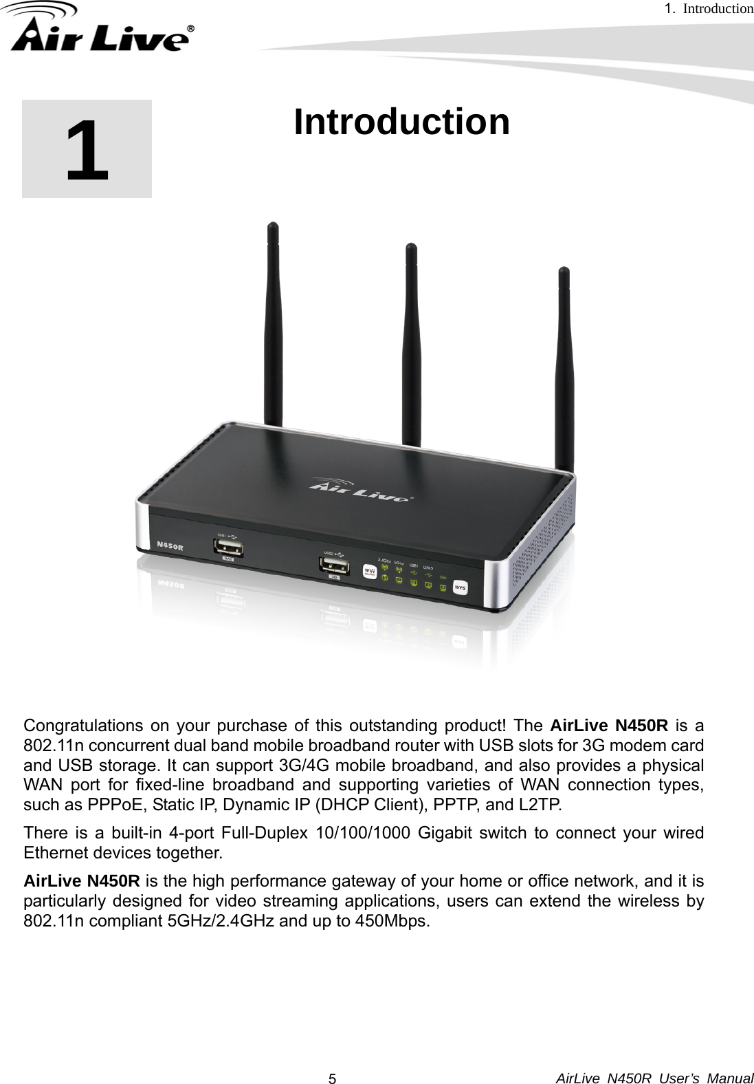
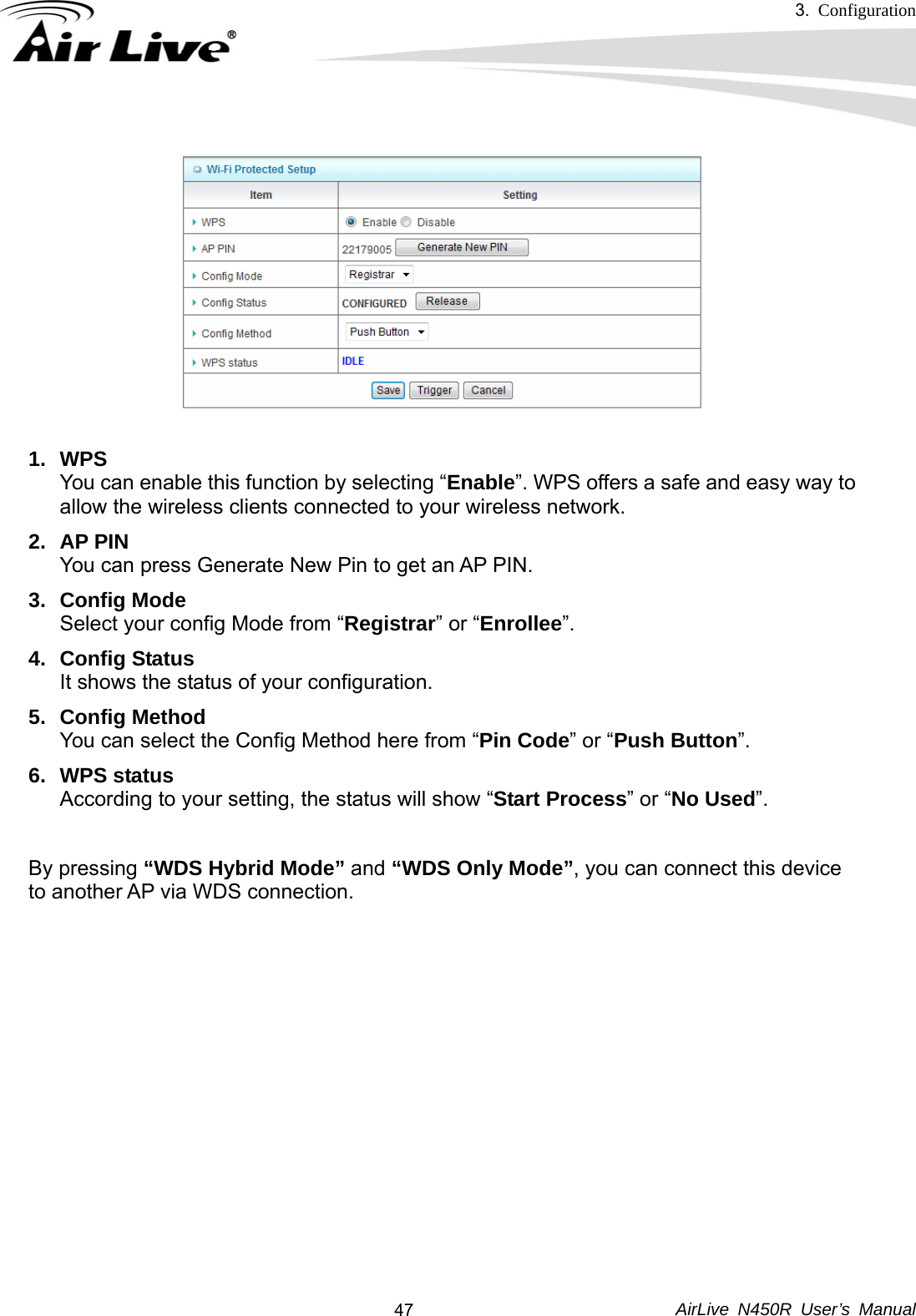
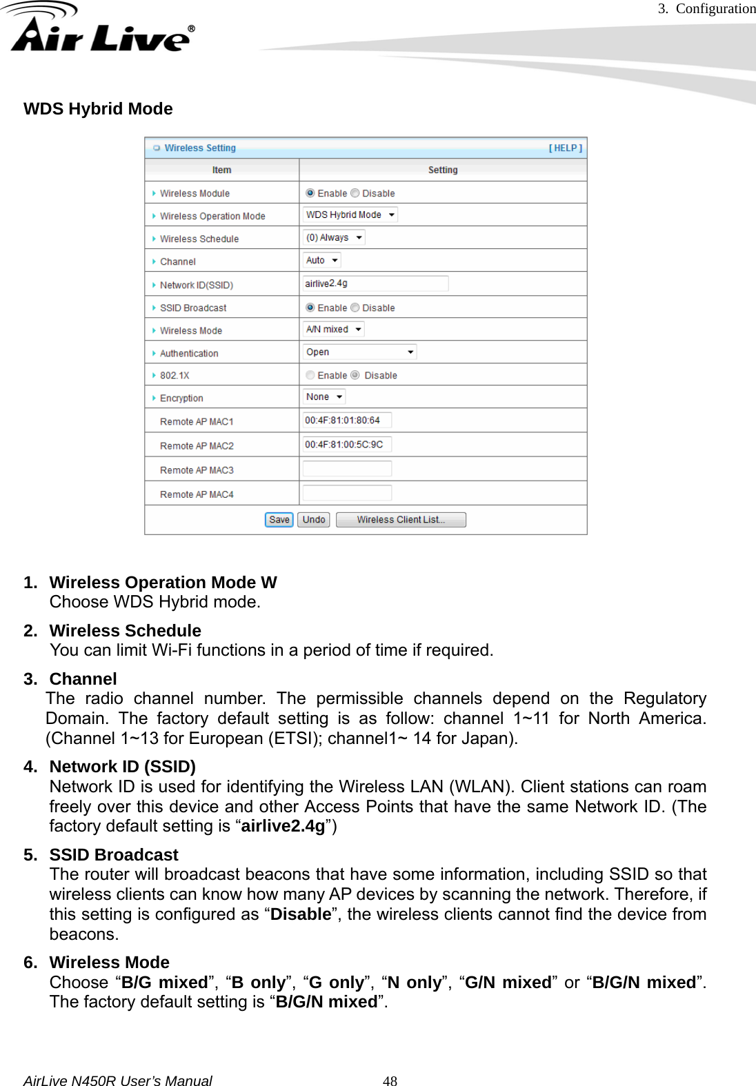
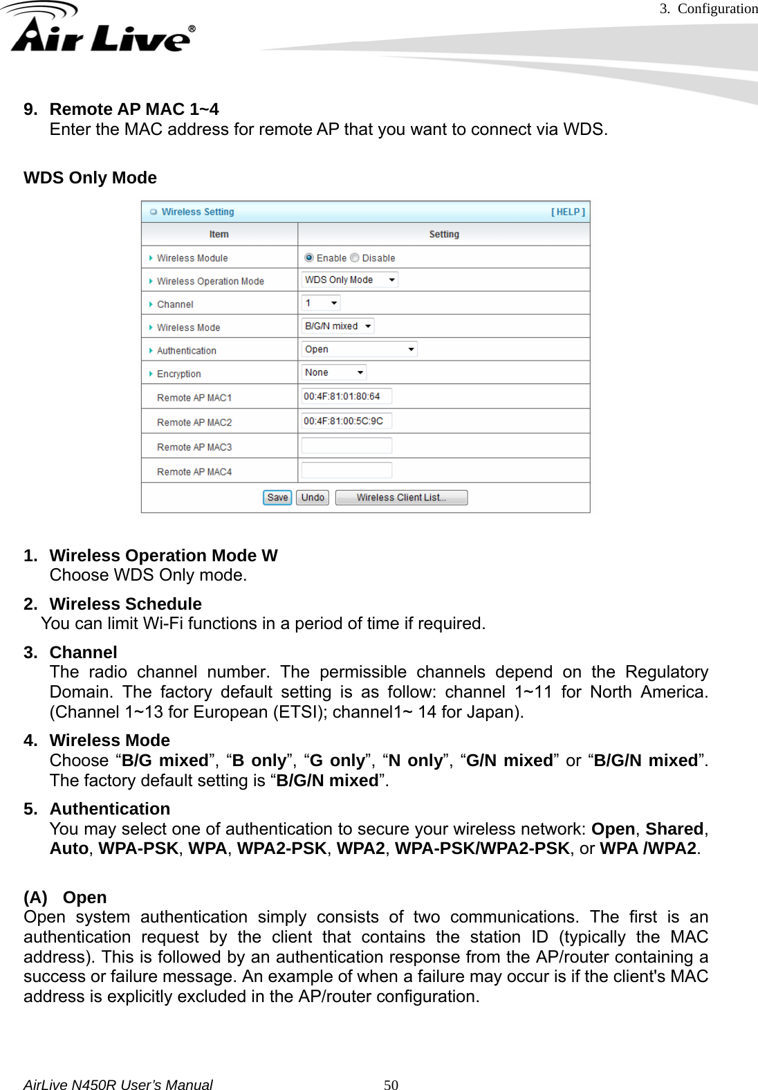
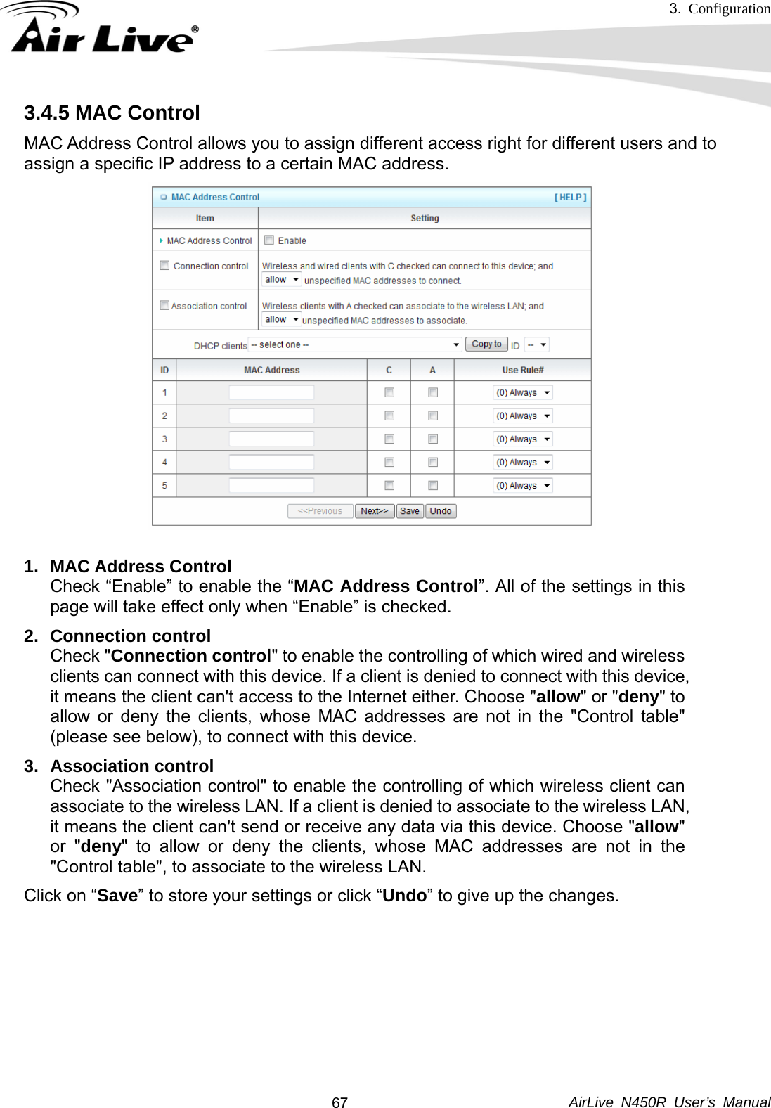
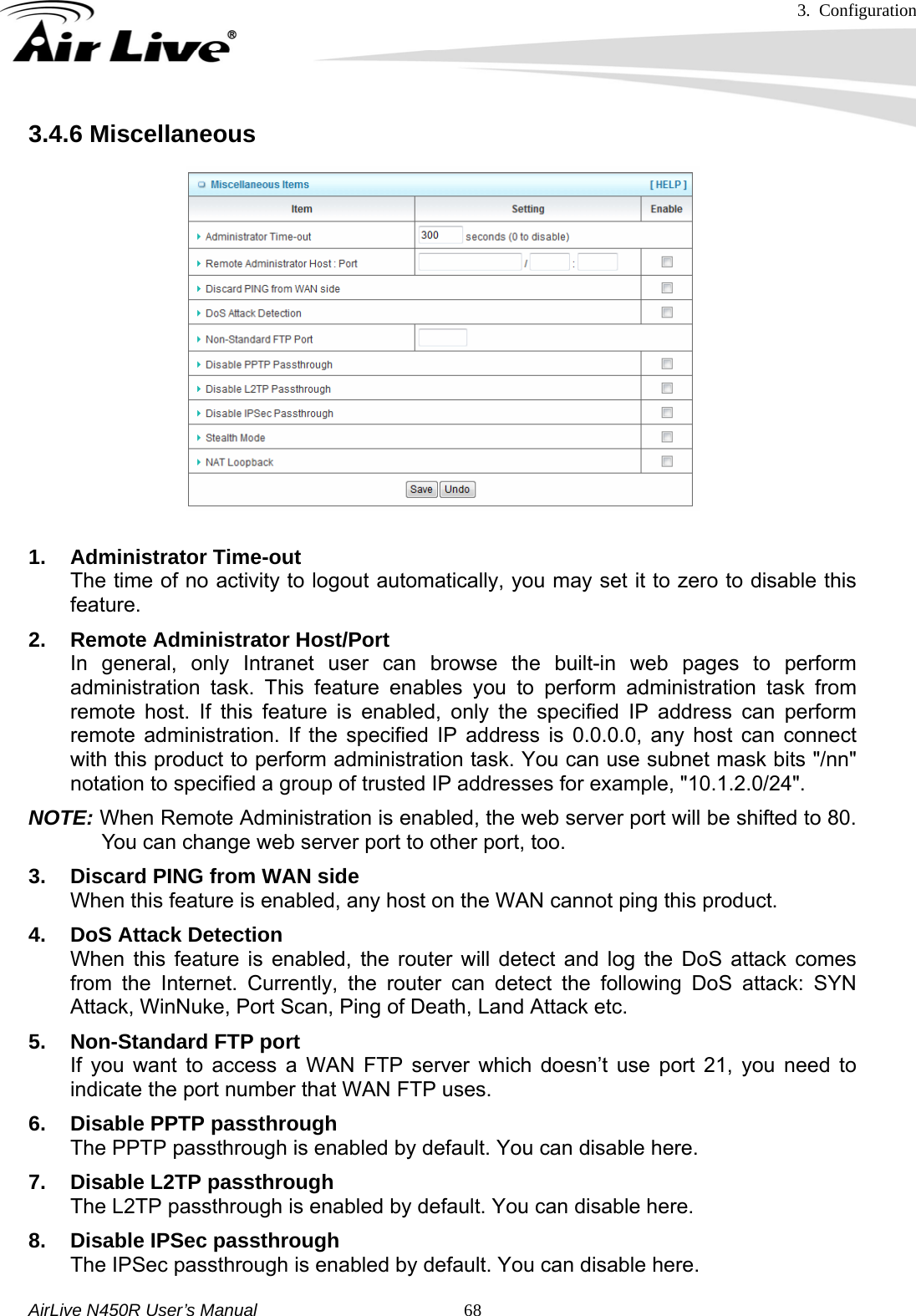
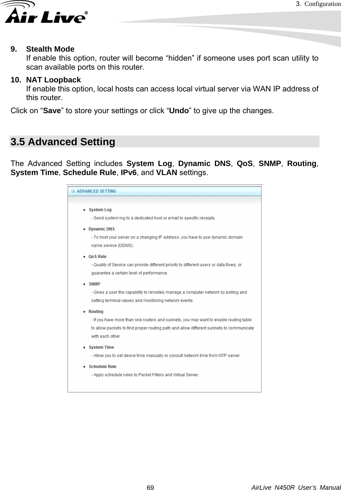
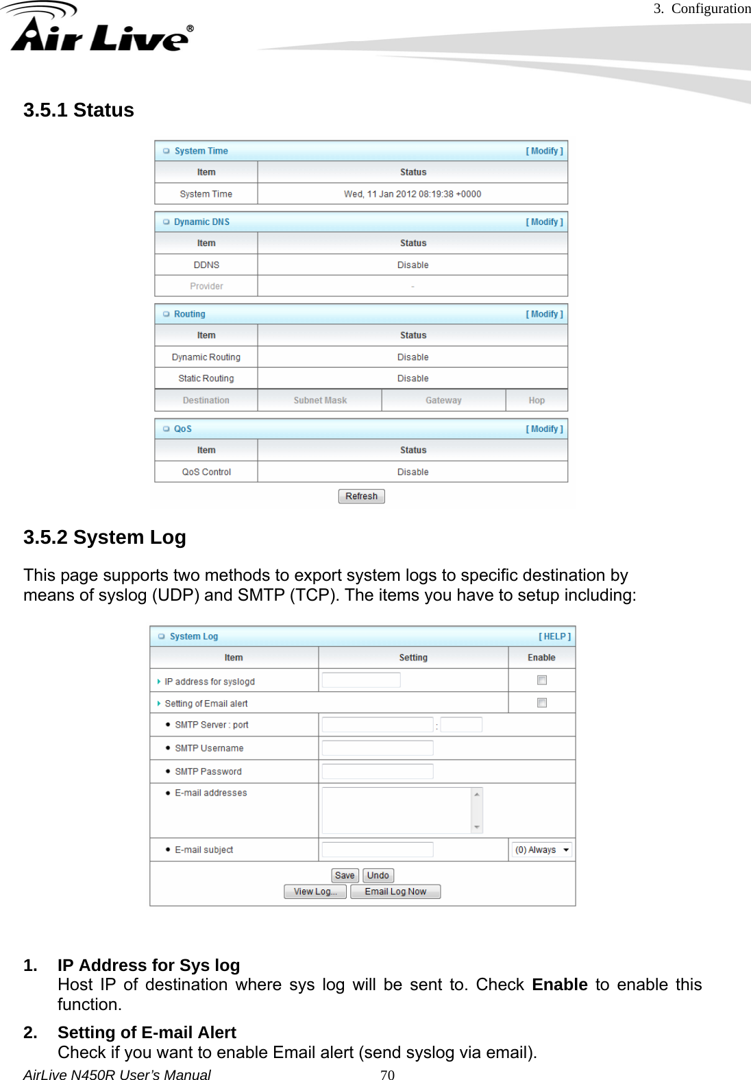
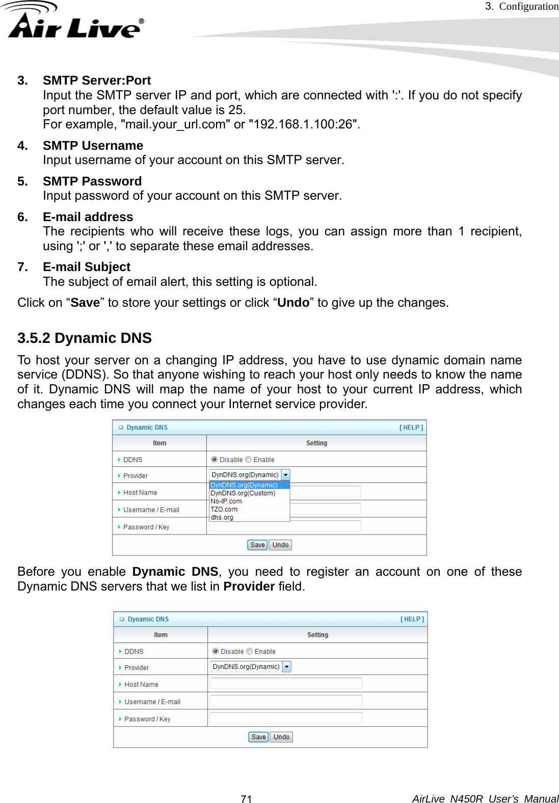
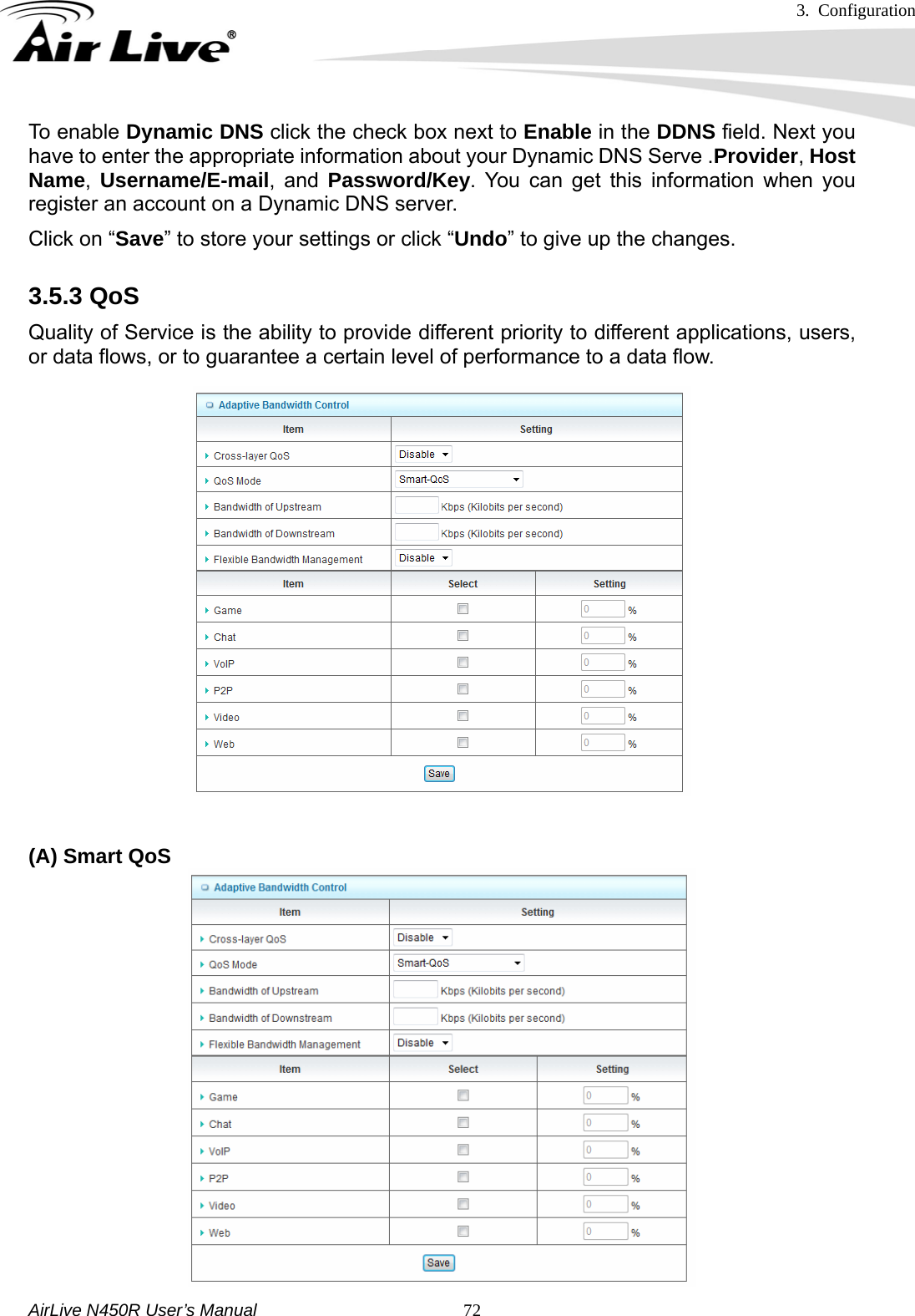
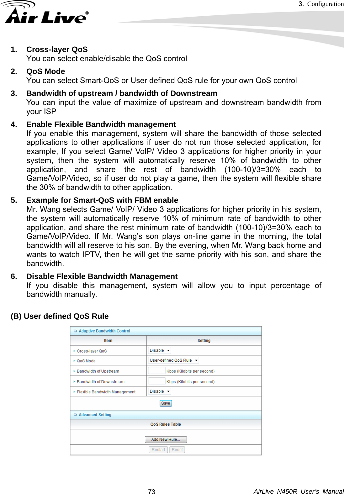
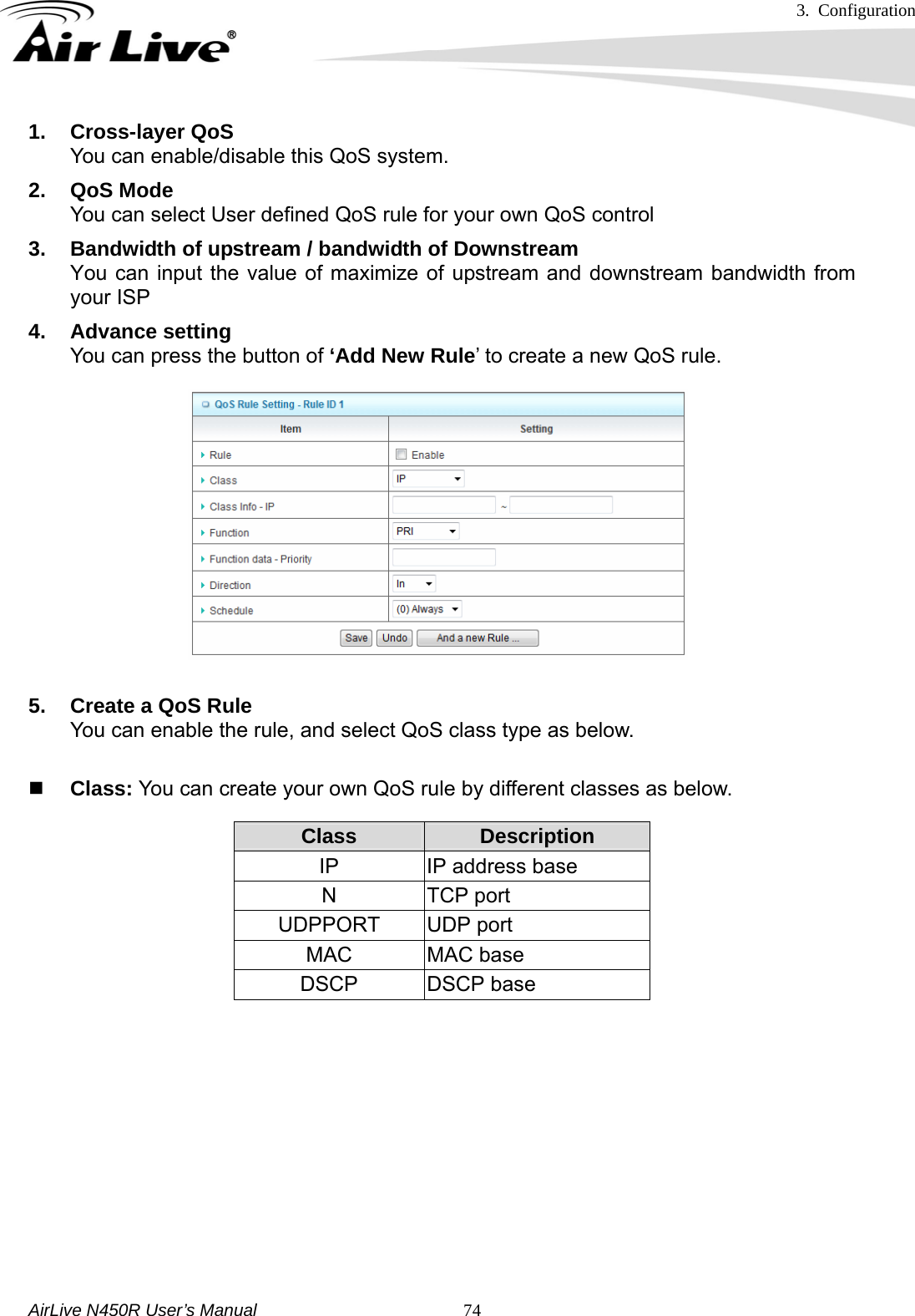
OvisLink N450R 3T3R WIRELESS-N DUAL BAND GIGABIT ROUTER User Manual 05 N450R
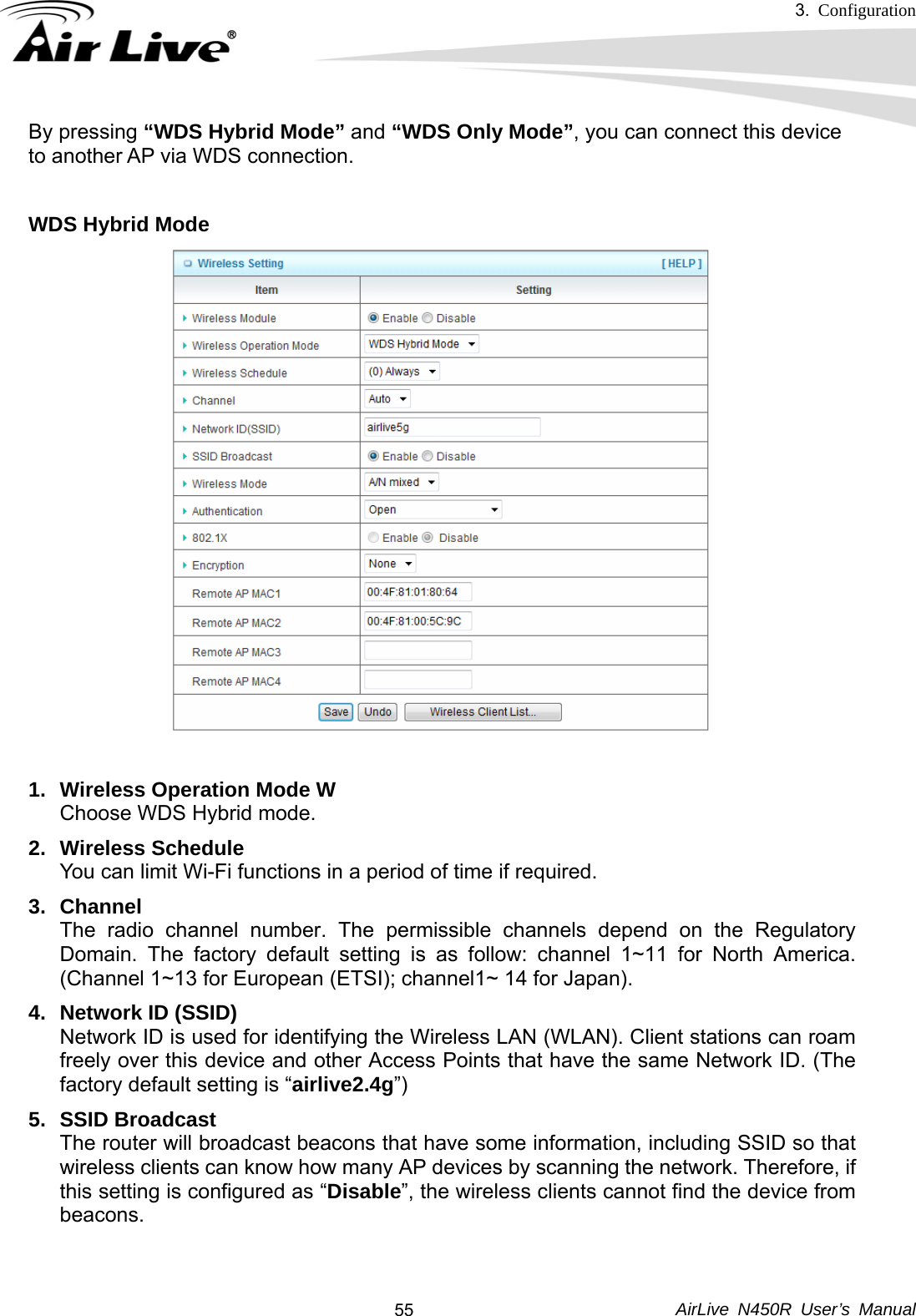
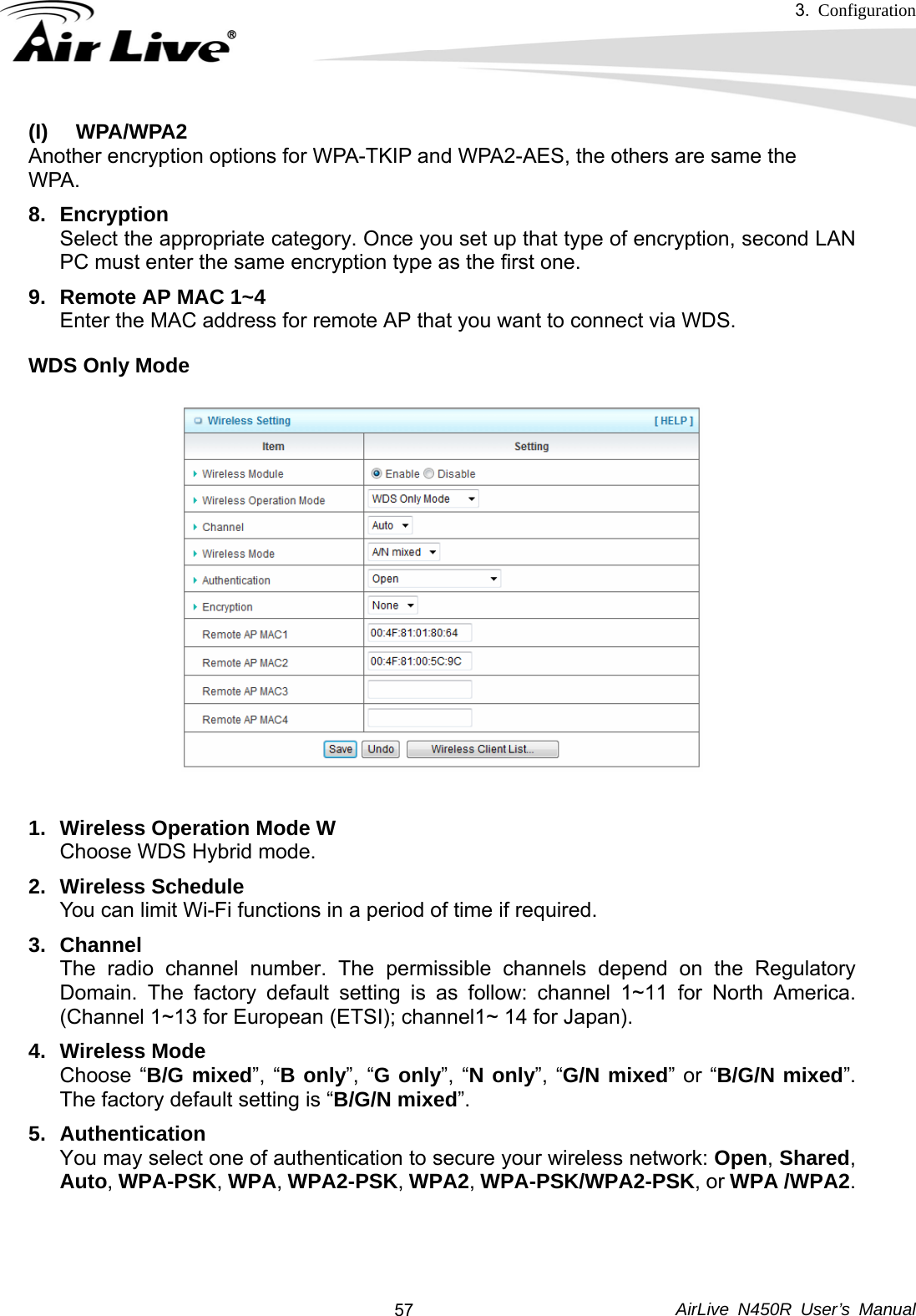
OvisLink Corp. 3T3R WIRELESS-N DUAL BAND GIGABIT ROUTER 05 N450R
UserManual.wiki
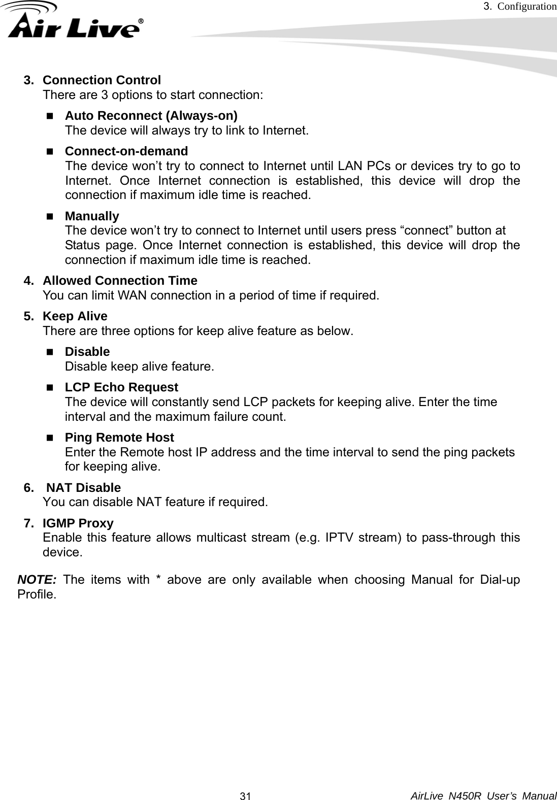
>
OvisLink
>
N450R User Manual
Users Manual
Navigation menu
Upload a User Manual
Namespaces
Wiki Guide
HTML
PDF
Info
Views
User Manual
Discussion / Help
Navigation