OvisLink SI101 Door/window sensor + Illumination + Temperature 3 in 1 Multi-sensor User Manual
OvisLink Corp. Door/window sensor + Illumination + Temperature 3 in 1 Multi-sensor Users Manual
OvisLink >
Users Manual
Table of Content
Add to/Remove from Z-WaveTM Network ........................................................................................................... 1
Z-WaveTM Notification ......................................................................................................................................... 2
Z-WaveTM Message Report .................................................................................................................................. 3
* Door/Window Report: ................................................................................................................................. 3
* Tamper Report: ............................................................................................................................................ 3
* Temperature Report: .................................................................................................................................... 3
* Illumination Report: .................................................................................................................................... 4
* Timing Report:............................................................................................................................................. 4
Power Up Procedure ............................................................................................................................................... 4
* Battery Power Check ................................................................................................................................... 4
* NWI ............................................................................................................................................................. 5
* Wake ............................................................................................................................................................ 5
Over The Air (OTA) Firmware Update .................................................................................................................. 5
Security Network .................................................................................................................................................... 5
Function DIP Switch .............................................................................................................................................. 5
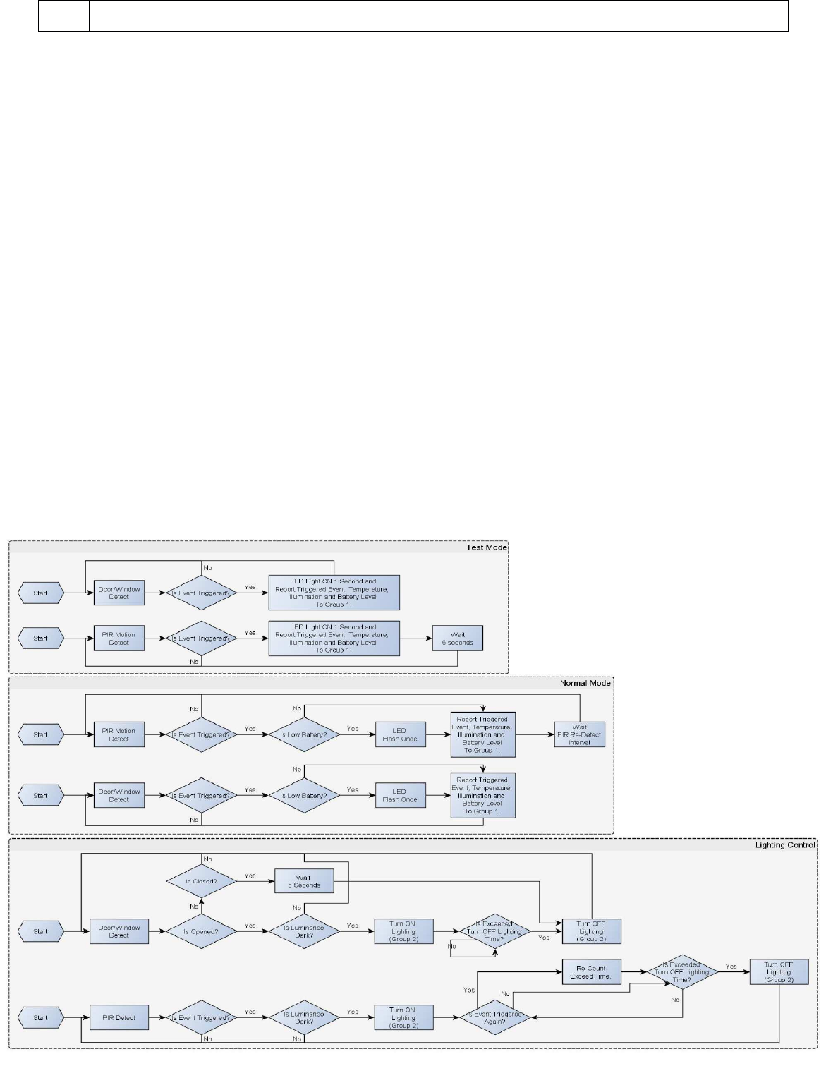
Operation Mode ...................................................................................................................................................... 6
Battery Installation ................................................................................................................................................. 7
Choosing a Suitable Location ................................................................................................................................. 7
Installation .............................................................................................................................................................. 8
Z-Wave Configuration Settings .............................................................................................................................. 8
Z-Wave Supported Command Class..................................................................................................................... 11
Specifications ....................................................................................................................................................... 12
FCC Interference Statement ................................................................................................................................. 13
Warning ................................................................................................................................................................ 13

1
SI-101
3 in 1 Multi-sensor
The slim multi-sensor has door/window, temperature and illumination, 3 sensors function in one, based on
Z-Wave
TM
technology.
It is the Z-Wave
TM
plus product, it support the security, OTA. Those newest features of the Z-Wave
TM
technology. Z-Wave
TM
is a wireless communication protocol designed for home automation, specifically to
remotely control applications in residential and light commercial environments. The technology uses a
low-power RF radio embedded or retrofitted into home electronics devices and systems, such as lighting, home
access control, entertainment systems and household appliances.
This product can be included and operated in any Z-Wave
TM
network with other Z-Wave
TM
certified devices
from other manufacturers and/or other applications. All non-battery operated nodes within the network will act
as repeaters regardless of vendor to increase reliability of the network.
The device adopts the Z-Wave
TM
500 series chip, when your Z-Wave
TM
network system is all made by
Z-Wave
TM
500 series devices. The network system will have the advantages as below.
• Concurrent multi-channel support reduces external interference.
• Better RF range, improve about 10 meters in indoor.
• Support 100 Kbps transmit speed, speed up communication.
Add to/Remove from Z-Wave
TM
Network
There are two tamper keys in the device, one is in the back side, another is in the front side. Both of them can
add, remove, reset or association from Z-Wave
TM
network.
In the first time, add the device into the Z-Wave
TM
network. First, make sure the primary controller is in the add
mode. And then power on the device, just take out the insulation Mylar in the back side of the device. The
device will auto start the NWI (Network Wide Inclusion) mode. And it should be included in 5 seconds. You
will see the LED light ON one second.

2
Notice: Including a node ID allocated by Z-Wave
TM
Controller means “Add” or “Inclusion”. Excluding a node
ID allocated by Z-Wave
TM
Controller means “Remove” or “Exclusion”.
Function
Description
Add
1.
Have Z
-
Wave
TM
Controller entered inclusion mode.
2. Pressing tamper key three times within 1.5 seconds to enter the inclusion mode.
3. After add successful, the device will wake to receive the setting command
from Z-Wave
TM
controller about 20 seconds.
Remove
1.
Have Z
-
Wave
TM
Controller entered exclusion mode.
2. Pressing tamper key three times within 1.5 seconds to enter the exclusion mode.
Node ID has been excluded.
Reset
Notice: Use this procedure only in the event that the primary controller is lost or
otherwise inoperable.
1. Pressing tamper key four times within 1.5 seconds and do not release the tamper key
in the 4th pressed and the LED will light ON.
2. After 3 seconds the LED will turn OFF, after that within 2 seconds, release the
tamper key. If successful, the LED will light ON one second. Otherwise, the LED
will flash once.
3. IDs are excluded and all settings will reset to factory default.
Association
1. Have Z-Wave
TM
Controller entered association mode.
2. Pressing tamper key three times within 1.5 seconds to enter the association mode.
Note: The device supports 2 groups. The group 1 is for receiving the report message, like
triggered event, temperature, illumination etc. The group 2 is for light control, the device
will send the “Basic Set” command to this group. And each group support 8 nodes
maximum.
Failed or success in add/remove the node ID can be viewed from Z-Wave
TM
Controller.
Notice 1: Always RESET a Z-Wave
TM
device before trying to add it to a Z-Wave
TM
network.
Notice 2: When the device into NWI mode, the sensor functionality will useless. The NWI mode will timeout
after 30 seconds. You can press the tamper key 3 times to abort the NWI mode.
Z-Wave
TM
Notification
After the device adding to the network, it will wake-up once per day in default. When it wake-up it will
broadcast the “Wake Up Notification” message to the network, and wake-up 10 seconds for receive the setting
commands.
The wake-up interval minimum setting is 30 minutes, and maximum setting is 120 hours. And the interval step
is 30 minutes.
If the user wants to wake-up the device immediately, please remove the front cover, and press the tamper key
once. The device will wake-up 10 seconds.

3
Z-Wave
TM
Message Report
When the door/windows triggered, the device will report the trigger event and also report the battery status,
temperature and illumination level.
In default the device will using Notification Report to represent the trigger event, it can be changed to Sensor
Binary Report by setting the configuration NO. 7 Bit4 to 1.
* Door/Window Report:
When the door/window state changed, the device will unsolicited to send the report to the nodes in the group 1.
Notification Report (V4)
Notification Type: Access Control (0x06)
Event: Door/Window is open (0x16)
Door/Window is closed (0x17)
Sensor Binary Report (V2)
Sensor Type: Door/Window (0x0A)
Sensor Value: 0x00 is closed, 0xFF is opened.
* Tamper Report:
Both the 2 tamper keys are pressed over 5 seconds. The device will into the alarm state. In that state, if any one
of the tamper keys be released, the device will unsolicited to send the report to the nodes in the group 1.
Notification Report (V4)
Notification Type: Home Security (0x07)
Event: Tamperin
g. Product covering removed (0x03)
Sensor Binary Report (V2)
Sensor Type: Tamper (0x08)
Sensor Value: 0xFF
* Temperature Report:
When the door/window state changed, the device will unsolicited to send the “Sensor Multilevel Report” to the
nodes in the group 1.
Sensor Type: Temperature (0x01)
Note: To disable this functionality by setting the configuration N0.5 bit5 to 1.
*** Temperature differential report ***
This function default is enabled, to disable this function by setting the configuration NO.21 to 0.
In the default, when the temperature is changed to plus or minus one degree Fahrenheit (0.56 degree Celsius),
the device will report temperature information to the nodes in the group 1.

4
The device will measure the temperature in every one minute. And if the temperature is over 140 degree
Fahrenheit (60 degree Celsius), the device will always report in each measurement.
* Illumination Report:
When the door/window state changed, the device will unsolicited to send the “Sensor Multilevel Report” to
the nodes in the group 1.
Sensor Type: Luminance (0x03)
Note: To disable this functionality by setting the configuration N0.5 bit4 to 1.
*** Illumination differential report ***
This function default is disabled, to enable this function by setting the configuration NO.22 not to zero.
Enable this functionality, the device will measure the illumination in every one minute. And if the illumination
is changed to plus or minus the value (setting by the configuration NO.22), the device will report illumination
information to the nodes in the group 1.
Caution 1: Enable this function will reduce the battery life about 15% ~ 20%. And another issue is setting the
differential value too small, it will cause report too frequency, shorter the battery life more. Propose the setting
differential value should not small than 10.
Caution 2: If the configuration No.4 is setting to 0 or 100, this functionality is useless.
* Timing Report:
Beside the event triggered could report message, the device also support the timing unsolicited report of the
status.
• Battery level report: Every 6 hours report once in default. It could be changed by setting the
configuration NO. 10.
• Low battery report: When the battery level is too low, every 30 minutes will report once.
• Door/window state report: Every 6 hours report once in default. It could be changed by setting the
configuration NO. 11.
• Illumination level report: Every 6 hours report once in default. It could be changed by setting the
configuration NO. 12.
• Temperature report: Every 6 hours report once in default. It could be changed by setting the
configuration NO. 13.
Notice: The configuration NO. 10, 11, 12 and 13 could be setting to zero to disable the auto report. And the
configuration NO. 20 could change the tick interval, the default value is 30, if setting to 1, that means the
minimum auto report interval will be one minute. And please notice if setting this value to zero, that means
disable all of the timing report except the low battery detection.
Power Up Procedure
* Battery Power Check
When the device power up, the device will detect the power level of the battery immediately. If the power level
is too low, the LED will continue flash about 5 seconds. Please change another new battery.

5
* NWI
When the device power on, the device will check is it already adding to the network? If doesn't, it will auto
start the NWI mode. The LED will flash in every second and continue 30 seconds. Until timeout or the device
successful to inclusion by controller. The use can press the tamper key 3 times to abort the NWI mode.
* Wake
When the device power on, the device will wake about 20 seconds. In this duration, the controller can
communicate with the device. Normally the device is always sleeping to save the battery energy.
Over The Air (OTA) Firmware Update
The device supports the Z-Wave firmware update via OTA.
Before starting the procedure, please remove the front cover of the device. Otherwise the hardware check will
be failed.
Let the controller into the firmware update mode, and then press the front tamper key once to start the update.
After finish the firmware download, the LED will start flash in every 0.5 second. At that time, please don't
remove the battery, otherwise it will cause the firmware broken, and the device will no function.
After the LED stops flash, it is recommended that the user power up the device. Caution: After remove the
battery, please wait about 30 seconds, and then re-install the battery.
Security Network
The device supports the security function. When the device included with a security controller, the device will
auto switch to the security mode. In the security mode, the follow commands need using Security CC wrapped
to communicate, otherwise it will not response.
COMMAND_CLASS_BATTERY COMMAND_CLASS_NOTIFICATION_V4
COMMAND_CLASS_ASSOCIATION_V2 COMMAND_CLASS_CONFIGURATION
COMMAND_CLASS_SENSOR_BINARY_V2 COMMAND_CLASS_SENSOR_MULTILEVEL_V5
COMMAND_CLASS_WAKE_UP_V2
Function DIP Switch
There is one function DIP switch in front of the device.
Remove the front cover in the right top of the PCB, and also has mark “M1” and “M2” for two switch.
Notice: SI-101-C don't have DIP switch in hardware.
M1
M2
Description
ON
ON
Test Mode.
ON
OFF
Normal Mode.
OFF
ON
Normal Mode.
6
OFF
OFF
Customer Mode. According to the configuration setting NO. 5 to set the operation mode.
Operation Mode
There are two modes “Test” and “Normal”.
“Test Mode” is for the user test the sensor function when installation. “Normal Mode” for the normal operation.
When the event triggered, normally the LED won't indicated, unless the battery is in the low level, the LED
will flash once. But in the “Test Mode” the LED also will light ON one second.
When the event triggered, the device will report the messages to the nodes in the group 1. The messages also
include the battery level, the temperature and the illumination level. The user can switch the report by setting
the configuration NO. 5 bit4 (illumination) and bit5 (temperature), and the configuration NO. 7 bit6 (battery).
When the event triggered, if the environment luminance is less than the setting of the value of the configuration
NO. 4, the device will emit the signal to turn ON the lighting equipment, those nodes are in the group 2. And
delay a while to turn OFF the lighting equipment. The delay time is setting by the configuration NO. 9.
Notice: When the tamper key of the back side is released, the device always in the “Test Mode”, no matter the
DIP switches setting.
7
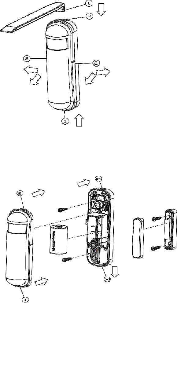
Battery Installation
When the device report the low battery message. The user should replace the battery to new one. The
battery type is CR123A, 3.0V.
The way to open the front cover please follow below steps.
1. Using a tool to press the 1-1 position, to release the cover.
2. Hold the front cover and pull back
3. Hold the front cover and pull up
Replace the new battery and install the cover back.
1. Put the front cover bottom to 1-1, and press down.
2. Push the front cover top to 2-1.
Choosing a Suitable Location
1. The recommended mounting height is 160cm
2. Don't let the device facing the window or the sunlight.
3. Don't let the device facing the source of heat. For instance the heater or the air-condition.
8
Installation
1. In the first time, add the device into the Z-Wave
TM
network. First, make sure the primary controller is in
the inclusion mode. And then power on the device, just take out the insulation Mylar in the back side of the
device. The device will auto start the NWI (Network Wide Inclusion) mode. And it should be included in 5
seconds. You will see the LED light ON one second.
2. Let the controller associate with the device into the first group, any light switch that intend to be turned on
when the device trig please associate with the device into the second group.
3. In the accessory pack. There are two type of double coated tape, one is thicker (hereinafter referred to as A
tape) and another is thinner (hereinafter referred to as B tape), you can use A tape for the test at the beginning.
The right way for A tape installation is stick it to the position below tamper key. The thicker tape won't let the
tamper key pressed, so the sensor will enter the test mode, you may test if installed position is good or not by
this way.
After finish the test and decide to fix, then you can remove tape A, and mounting the sensor by using tape B.
The tamper key will pressed and let the sensor enter normal mode.
Z-Wave Configuration Settings

9
Notice:
* All of the configuration, the data size is 1.
* The configuration mark with star(*), means after the remove the setting still keep, don't reset to factory
default. Unless the user execute the “RESET” procedure.
* The reserve bit or not supported bit is allowed any value, but no effect.
NO.
Name Def. Valid Description
2
Basic Set Level
OxFF All
Setting the BASIC command value to turn on the light. The
0xFF(-1) means turn on the light. For dimmer equipment 1 to
100 means the light strength.
0 means turn off the light.
4 Light
Threshold 99 0~100
Setting the illumination threshold to turn on the light. When the
event triggered and the environment illumination lower then the
threshold, the device will turn on the light.
0 means turn off illumination detected function. And never turn
on the light. 1 means darkest.
99
means brightest.
100
means turn off illumination detected function. And
always turn on the light.
Notice: In none test mode, only the value in 1 to 99 will enable the
illumination detected function and update the illumination value.
5(*)
Operation
Mode
0 All Operation mode. Using bit to control.
Caution: The value is unsigned byte, the range is from 0x00 ~
0xFF.
0
Bit1: 1 means test mode,
0 means normal mode.
Notice:
This bit only effect by the DIP Switch setting to “customer
mode”, otherwise it decides by DIP Switch setting to Test or
Normal Mode.
0
Bit2: Disable the door/window function. (1:Disable, 0:Enable)
0
Bit3: Setting the temperature scale. 0: Fahrenheit, 1:Celsius
0
Bit4: Disable the illumination report after event triggered.
(1:Disable, 0:Enable)
0
Bit5: Disable the temperature report after event triggered.
(1:Disable, 0:Enable)

1
0
0
Bit7: Disable the back key release into test mode. (1:Disable,
0:Enable)
NO.
Name Def. Valid Description
6(*)
Mult- Sensor
Function
Switch
4 All Multisensor function switch. Using bit to control
0
Bit0: Disable magnetic integrate illumination to turn ON the
lighting nodes in the association group 2. (1:Disable,
0:Enable)
0
Bit4: Disable delay 5 seconds to turn off the light, when
door/window closed.
0
Bit5: Disable auto turn off the light, after door/window opened
to turn on the light. (1:Disable, 0:Enable)
Notice: If bit2 is zero, this setting is useless.
Notice: If the configuration No.9 is zero, this setting is useless.
7(*)
Customer
Function
4 All Customer function switch, using bit control.
0
Bit3: Disable send out BASIC OFF after door closed.
(1:Disable, 0:Enable)
0
Bit4: Notification Type,
0: Using Notification Report. 1: Using Sensor Binary
Report.
0
Bit5: Disable Multi CC in auto report. (1:Disable, 0:Enable)
0
Bit6: Disable to report battery state when the device triggered.
(1:Disable, 0:Enable)
9
Turn Off
Light Time
4
0 ~
127
8 seconds per tick, default tick is 4 (32 seconds).
0 means never send turn off light command.
10
Auto Report
Battery Time
12
0 ~
127
The interval time for auto report the battery level.
0 means turn off auto report battery. The default value is 12. The
tick time can setting by the configuration No.20.
11
Auto Report
Door/Windo
w
State
12
0 ~
127
The interval time for auto report the door/window state.
0 means turn off auto report door/window state.
The default value is 12. The tick time can setting by the
configuration No.20.
12
Auto Report
Illumination
Time
12
0 ~
127
The interval time for auto report the illumination.
0 means turn off auto report illumination.
The default value is 12. The tick time can setting by the

11
configuration No.20.
NO.
Name Def. Valid Description
13
Auto Report
Temperature
Time
12
0 ~
127
The interval time for auto report the temperature.
0 means turn off auto report temperature.
The default value is 12. The tick time can setting by the
configuration No.20.
20
Auto Report
Tick Interval
30
0 ~
0xFF
The interval time for auto report each tick. Setting this
configuration will effect configuration No.10, No.11, No.12 and
No.13.
Caution: Setting to 0 means turn off all auto report function.
21
Temperature
Differential
Report
1
0 ~
0x7F
The temperature differential to report. 0 means turn off this
function.
The unit is Fahrenheit.
Enable this function the device will detect every minute.
And when the temperature is over 140 degree Fahrenheit, it will
continue report.
Enable this functionality will cause some issue please see the
detail in the
“Temperature Report” section.
22
Illumination
Differential
Report
0
0 ~
0x63
The illumination differential to report. 0 means turn off this
function.
The unit is percentage.
Enable this function the device will detect every minute.
Enable this functionality will cause some issue please see the
detail in the
“Illumination Report” section.
Z-Wave Supported Command Class
COMMAND_CLASS_ZWAVEPLUS_INFO_V2 COMMAND_CLASS_BATTERY
COMMAND_CLASS_NOTIFICATION_V4 COMMAND_CLASS_ASSOCIATION_V2
COMMAND_CLASS_CONFIGURATION COMMAND_CLASS_MANUFACTURER_SPECIFIC_V2
COMMAND_CLASS_VERSION_V2 COMMAND_CLASS_SENSOR_BINARY_V2
COMMAND_CLASS_SENSOR_MULTILEVEL_V5 COMMAND_CLASS_WAKE_UP_V2
COMMAND_CLASS_ASSOCIATION_GRP_INFO COMMAND_CLASS_POWERLEVEL
COMMAND_CLASS_DEVICE_RESET_LOCALLY COMMAND_CLASS_MULTI_CMD
COMMAND_CLASS_SECURITY COMMAND_CLASS_FIRMWARE_UPDATE_MD_V2
COMMAND_CLASS_MARK
COMMAND_CLASS_BASIC

1
2
Specifications
Power by CR123A lithium battery.
Signal (Frequency):
SI-101: 868.40 MHz, 869.85 MHz(EU),
SI-101: 908.40 MHz, 916.00 MHz(US),
SI-101: 922~927 MHz(JP/TW),
SI-101: 921.40 MHz, 919.80 MHz(ANZ),
SI-101: 869.00 MHz(RU),
SI-101: 865.20 MHz(IN),
SI-101-IL:916.00 MHz(IL),
Range:
Minimum 40 meters indoor,
100 meters outdoor line of sight.
RF Maximum Power: +5dBm
Operating Temperature: -10oC ~ 40oC
For indoor use only.
Specifications subject to change without notice due to continuing product improvement.
OvisLink Corp.,
http://www.airlive.com/
TEL: +886 2 2218 6888
FAX: +886 2 2918 6988

1
3
FCC ID: ODMSI101
FCC Interference Statement
This equipment has been tested and found to comply with the limits for a Class B digital device, pursuant to
Part 15 of the FCC Rules. These limits are designed to provide reasonable protection against harmful
interference in a residential installation. This equipment generates uses and can radiate radio frequency energy
and, if not installed and used in accordance with the instructions, may cause harmful interference to radio
communications. However, there is no guarantee that interference will not occur in a particular installation. If
this equipment does cause harmful interference to radio or television reception, which can be determined by
turning the equipment off and on, the user is encouraged to try to correct the interference by one of the
following measures:
• Reorient or relocate the receiving antenna.
• Increase the separation between the equipment and receiver.
• Connect the equipment into an outlet on a circuit different from that to which the receiver is connected.
• Consult the dealer or an experienced radio/TV technician for help.
This device complies with Part 15 of the FCC Rules. Operation is subject to the following two conditions:
(1) This device may not cause harmful interference, and
(2) This device must accept any interference received, including interference that may cause undesired
operation.
FCC Caution: Any changes or modifications not expressly approved by the party responsible for compliance
could void the user's authority to operate this equipment.
This transmitter must not be co-located or operating in conjunction with any other antenna or transmitter.
Warning
Do not dispose of electrical appliances as unsorted municipal waste, use separate collection facilities. Contact
your local government for information regarding the collection systems available. If electrical appliances are
disposed of in landfills or dumps, hazardous substances can leak into the groundwater and get into the food
chain, damaging your health and well-being.
When replacing old appliances with new once, the retailer is legally obligated to take back your old appliance
for disposal at least for free of charge.