OvisLink SMARTCUBE300W Intelligent 3MP Wireless Cube IPCAM with Temperature & Humidity Sensors User Manual CU 226 V1 1
OvisLink Corp. Intelligent 3MP Wireless Cube IPCAM with Temperature & Humidity Sensors CU 226 V1 1
OvisLink >
User manual
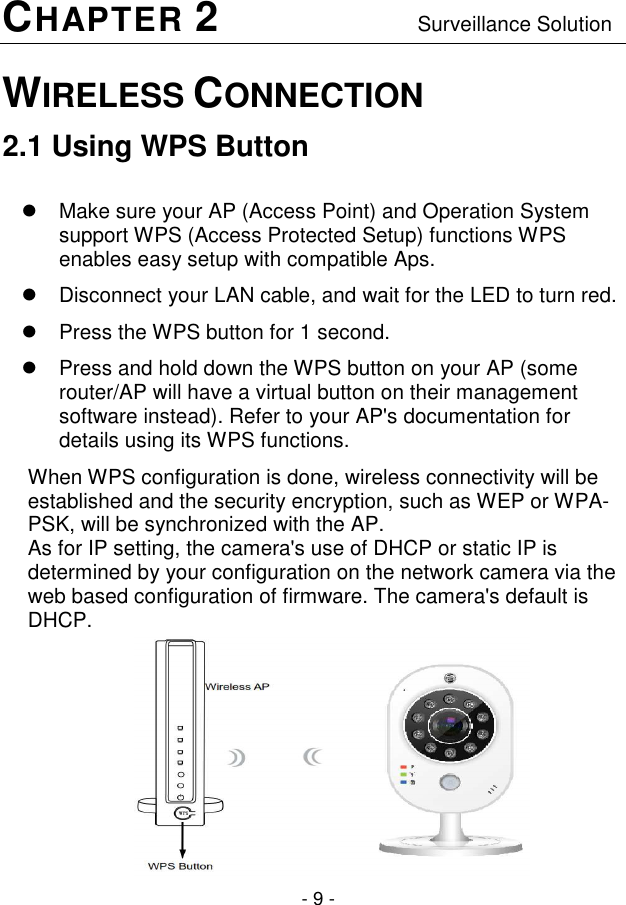
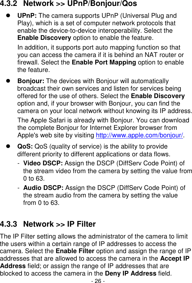
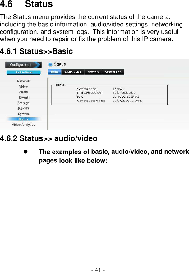
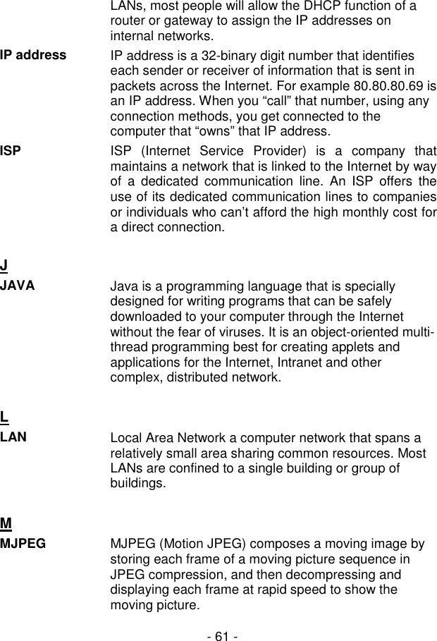
![- 17 - 3.3 Configuring the IP Address of the PC If you are failed to access to the camera, please check the IP address of your computer. When you connect the camera to your computer directly to proceed with configuration of the camera, you need to set up the IP addresses to be in the same segment for the two devices to communicate. 1. On your computer, click Start > Control Panel to open the Control Panel window. 2. Double-click Network Connection to open the Network Connection window. 3. Right-click Local Area Connection and then click Properties from the shortcut menu. 4. When the Local Area Connection Properties window appears, select the General tab. 5. Select Internet Protocol [TCP/IP] and then click Properties to bring up the Internet Protocol [TCP/IP] Properties window. 6. To configure a fixed IP address that is within the segment of the camera, select the Use the following IP address option. Then, enter an IP address into the empty field. The suggested IP address is 192.168.1.x (x is 1~254 except 99), and the suggested Subnet mask is 255.255.255.0. 7. When you are finished, click OK.](https://usermanual.wiki/OvisLink/SMARTCUBE300W/User-Guide-2940414-Page-18.png)