OvisLink WN370USB Long Range Wireless-B/G/N USB Dongle with Detachable Antenna User Manual AirLive WN 370USB QIG Manual
OvisLink Corp. Long Range Wireless-B/G/N USB Dongle with Detachable Antenna AirLive WN 370USB QIG Manual
OvisLink >
Users Manual

Live WN-370USB Manual
Long Range Wireless-B/G/N
USB Dongle with Detachable
Antenna
User’s Manual
W
N-370USB

Copyright and Disclaimer
AirLive WN-370USB User’s Manual
i
Copyright
The contents of this publication may not be reproduced in any part or as a whole, stored,
transcribed in an information retrieval system, translated into any language, or transmitted
in any form or by any means, mechanical, magnetic, electronic, optical, photocopying,
manual, or otherwise, without the prior written permission.
Trademarks
All products, company, brand names are trademarks or registered trademarks of their
respective companies. They are used for identification purpose only. Specifications are
subject to be changed without prior notice.

Copyright and Disclaimer
AirLive WN-370USB User’s Manual ii
FCC Interference Statement
This equipment has been tested and found to comply with the limits for a Class B digital
device pursuant to Part 15 of the FCC Rules. These limits are designed to provide
reasonable protection against radio interference in a commercial environment.
This equipment can generate, use and radiate radio frequency energy and, if not installed
and used in accordance with the instructions in this manual, may cause harmful
interference to radio communications. Operation of this equipment in a residential area is
likely to cause interference, in which case the user, at his own expense, will be required to
take whatever measures are necessary to correct the interference.
CE Declaration of Conformity
This equipment complies with the requirements relating to electromagnetic compatibility,
EN 55022/A1 Class B.
This device complies with Part 15 of the FCC Rules. Operation is subject to the
following conditions:
1) This device may not cause harmful interference and
2) This device must accept any interference received, including interference that may
cause undesired operation of the device.
NOTE
Please include the 20cm separation distance warning in the User Manual.
“Separation Distance” between the User and the EUT:“To maintain compliance with FCC’s
RF exposure guidelines, this equipment should be installed and operated with minimum
distance 20cm between the radiator and your body. Use only the supplied antenna(s).”

Copyright and Disclaimer
AirLive WN-370USB User’s Manual
iii
TABLE OF CONTENTS
1. INTRODUCTION .........................................................................................1
2. SPECIFICATION .........................................................................................3
3. INSTALLATION/ UN-INSTALLATION .........................................................5
3.1 Installation........................................................................................... 5
3.2 Un-Installation..................................................................................... 8
4. WLAN: WIRELESS LAN MANAGEMENT GUI ........................................11
4.1 Introduction of Main Window..............................................................11
4.2 Station Mode..................................................................................... 18
4.3 Access Point Mode ........................................................................... 25
5. APPENDIX.................................................................................................31
5.1 Troubleshooting ................................................................................ 31
5.2 Glossary............................................................................................ 32
1. Introduction
AirLive WN-370USB User’s Manual 1
1 1. Introduction
Thank you for purchasing Wireless LAN USB Adapter. Wireless LAN USB Adapter is a
perfect combination of both performance and cost-effective product introduced. It is
sincerely hoped that you can enjoy the wireless world through this solidly profiled wireless
adapter.
It provides a full solution of all the IEEE 802.11 b/g/n protocols, which pass the WiFi tests
and are compatible with all the wireless products with WiFi logo. If you have a Wireless LAN
USB Adapter on hand, it means you can connect to the wireless world without any difficulty.

1. Introduction
AirLive WN-370USB User’s Manual
2
It also provides all the data rates in the IEEE 802.11 b/g/n standards, with both short and
long preambles to ensure the compatibility of legacy wireless products and new ones,
saving the panic works for end users to find compatible products.
Since the security issue has become one of the most important one in the wireless society,
it provides you with the full security coverage from the 64/128bits WEP encryptions, second
generation WPA-PSK encryption, to the most advanced WPA2-AES encryption. WPA2 is
the latest security standard currently approved by WiFi standards.
Saving mode, Ad-hoc wireless LAN, Wake on LAN (WOL) and other exciting features are
also included in this Wireless LAN USB Adapter. This user manual will guide you through
these exciting features in the following chapters and we is believed that you will be greatly
satisfied with its performance and ease of use.
2. Specification
AirLive WN-370USB User’s Manual 3
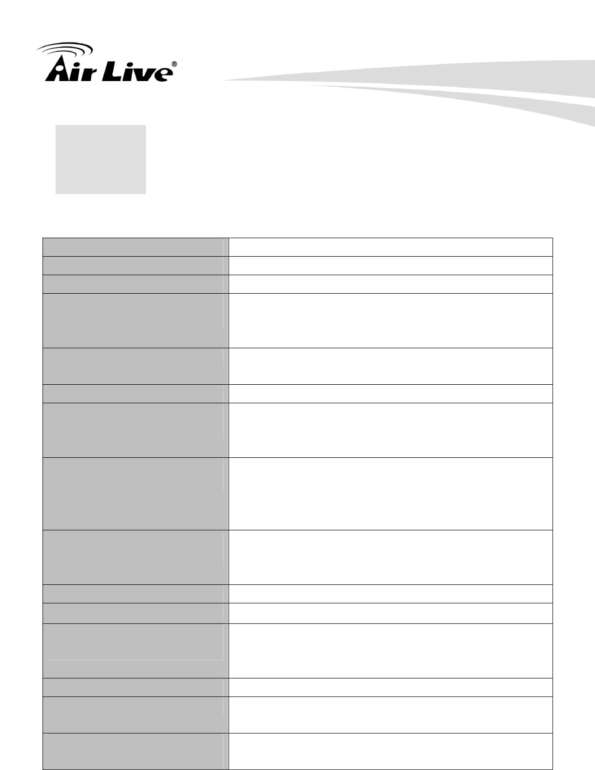
Standards IEEE 802.11 b/g/n standards compliant
Antenna 5dBi
Frequency Range 2.400GHz~2.4835GHz
Operating Frequency /
Channel
- 2.412~2.462GHz (Canada, FCC) / 11 Channels
- 2.412~2.484GHz (Japan, TELEC) / 14 Channels
- 2.412~2.472GHz (Euro, ETSI) / 13 Channels
Security - WEP 64/128
- WPA, WPA2
Access Protocol CSMA/CA
Output Power (HIGH-POWER)
- 11n: 19dBm (Typical) ± 1
- 11g: 20dBm (Typical) ±1
- 11b: 25dBm (Typical) ±1
Data Rate
- 11n (40MHz): up to 150Mbps
- 11n (20MHz): up to 72Mbps
- 11g: 54, 48, 36, 24, 18, 12, 9 and 6Mbps
- 11b: 11, 5.5, 2, and 1Mbps with auto-rate fall back
Sensitivity
- 11n: 90dBm
- 11g: 92dBm
- 11b: 95dBm
Host Interface A-Type USB 2.0 connector
Operation Voltage 5V DC
Environment Specifications
- Operating Temp : 0℃ to 60℃
- Storage Temp : -20℃ to 70℃
- Storage Humidity: 10% to 90% Non-Condensing
Physical Specifications 49(L) x 26(W) x 10(H) (not including antenna)
Operating System Support - Windows® 98SE/ME/2000/XP/VISTA/, Win 7, Mac and
Linux
Approval
- FCC Part 15
- CE
2 2. Specification

2. Specification
AirLive WN-370USB User’s Manual
4
SYSTEM REQUIREMENTS
Windows System: Windows, 2000, XP 32/64 bit, Vista 32/64 bit, and Win 7 32/64bit
PCs must have a device driver installed. It allows you to communicate with WLAN Mini USB
Adapter.
PACKAGE CONTENTS
1. Wireless LAN USB Adapter x 1
2. Installation Software CD x 1
3. Quick Setup Guide x 1
4. Antenna x 1
3. Installation/ Un-installation
AirLive WN-370USB User’s Manual 5
3 3. Installation/
Un-installation
Warning! Do not cover or block the airflow to the adapter. The adapter will reach a high
temperature during use.
3.1 Installation
Before you proceed with the installation, please notice the following descriptions.
Note1: The following installation was operated under Windows Vista. (Procedures are
similar for Windows /2000/XP.)
Note2: If you have installed the WLAN USB driver & utility before, please uninstall the old
version first.
1. Do not plug the wireless LAN USB adapter into your computer USB port before installing
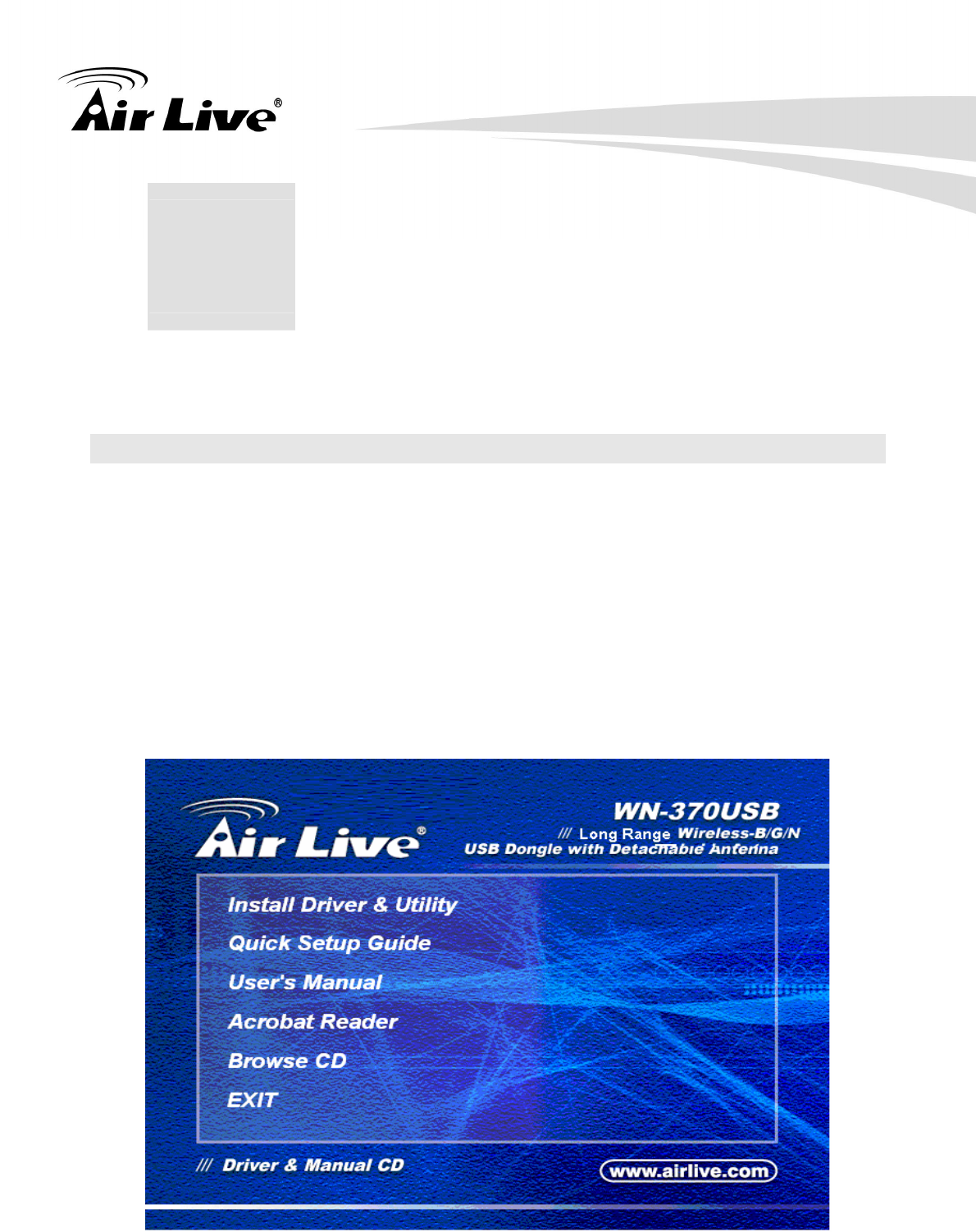
the software program. Insert the software program CD, then auto installation window pops
up on following:
2. While the following screen pops out, click Install Driver & Utility
3. Installation/ Un-installation
AirLive WN-370USB User’s Manual
6
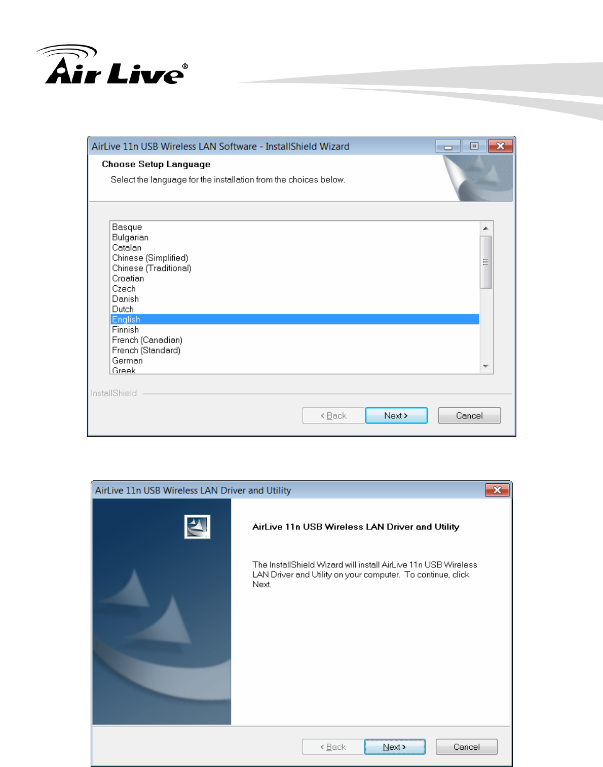
3. Choose a set up language. Click Next to process the installation.
4. Click Next
3. Installation/ Un-installation
AirLive WN-370USB User’s Manual 7
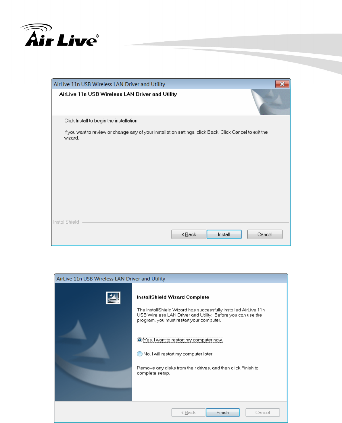
5. Click Install
6. Click Finish to complete the installation
3. Installation/ Un-installation
AirLive WN-370USB User’s Manual
8
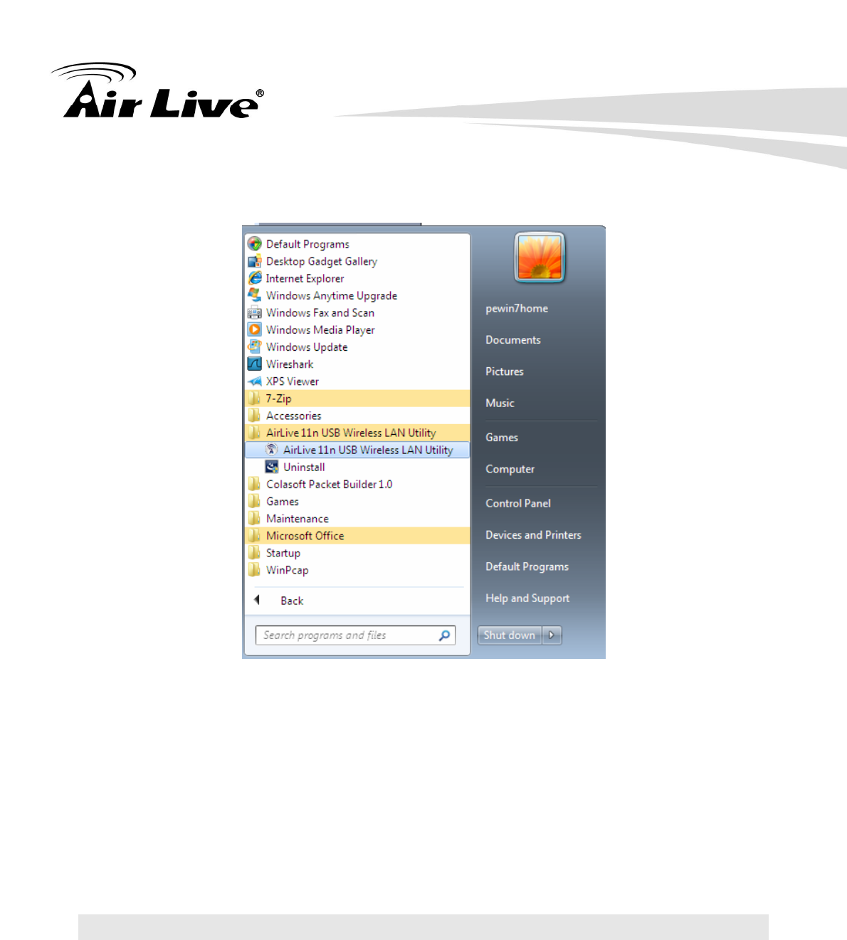
7. After click Finish to complete the installation, under Windows Vista <ALL Programs>
menu, AirLive USB wireless LAN Utility program installed.
8. Please connect the detachable antenna.
9. Insert the wireless LAN USB adapter into your computer USB port, the computer detect
and drive the wireless LAN USB adapter automatically.
Warning! For avoid damage the device, please connect the detachable antenna before
connect to the power (or USB).
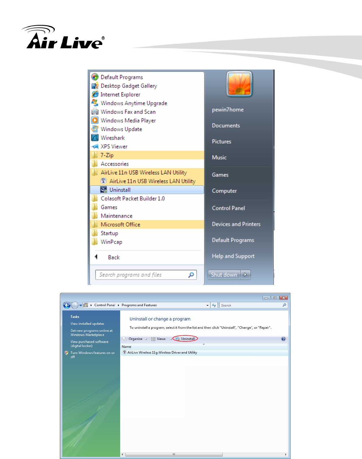
3.2 Un-Installation
From “Wireless Network Driver and Utility”, “Control Panel” ”Change or Remove Programs”.
A. Uninstall the WLAN USB Adapter Driver from “Start”, “All Programs”, Click “Uninstall” (or
“Change/Remove”) to remove Wireless LAN USB Adapter driver.
3. Installation/ Un-installation
AirLive WN-370USB User’s Manual 9
3. Installation/ Un-installation
AirLive WN-370USB User’s Manual
10
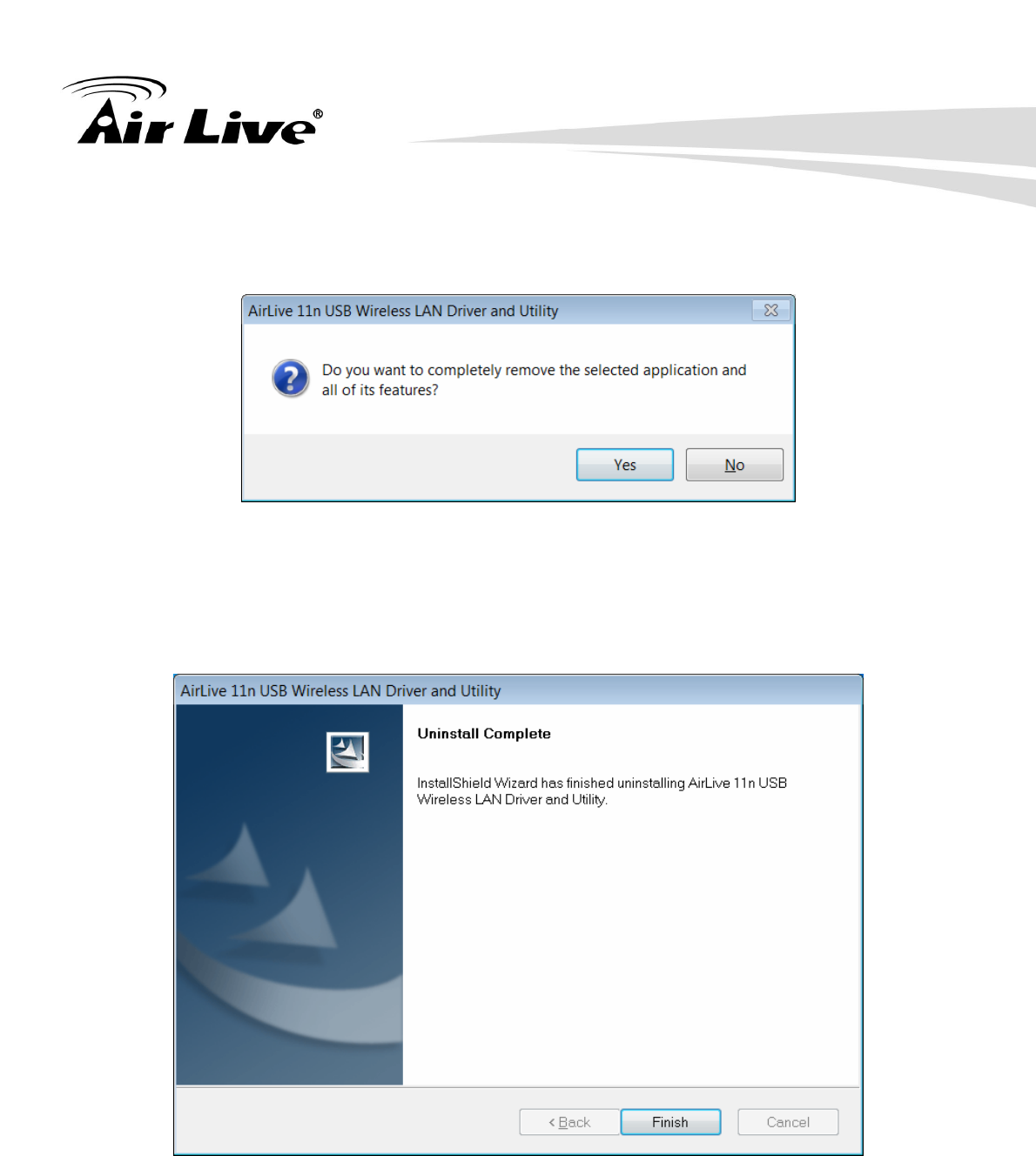
B. Click “Yes” if you want to remove Wireless LAN USB Adapter Driver.
Click “Finish” to complete the Un-installation.
4. WLAN: Wireless LAN Management GUI
AirLive WN-370USB User’s Manua 11
4 4. WLAN: Wireless LAN
Management GUI
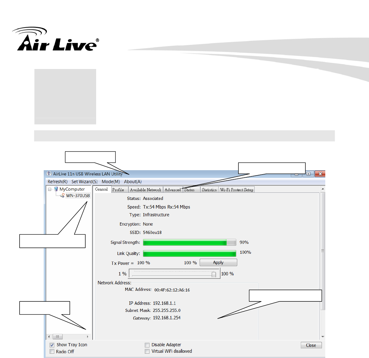
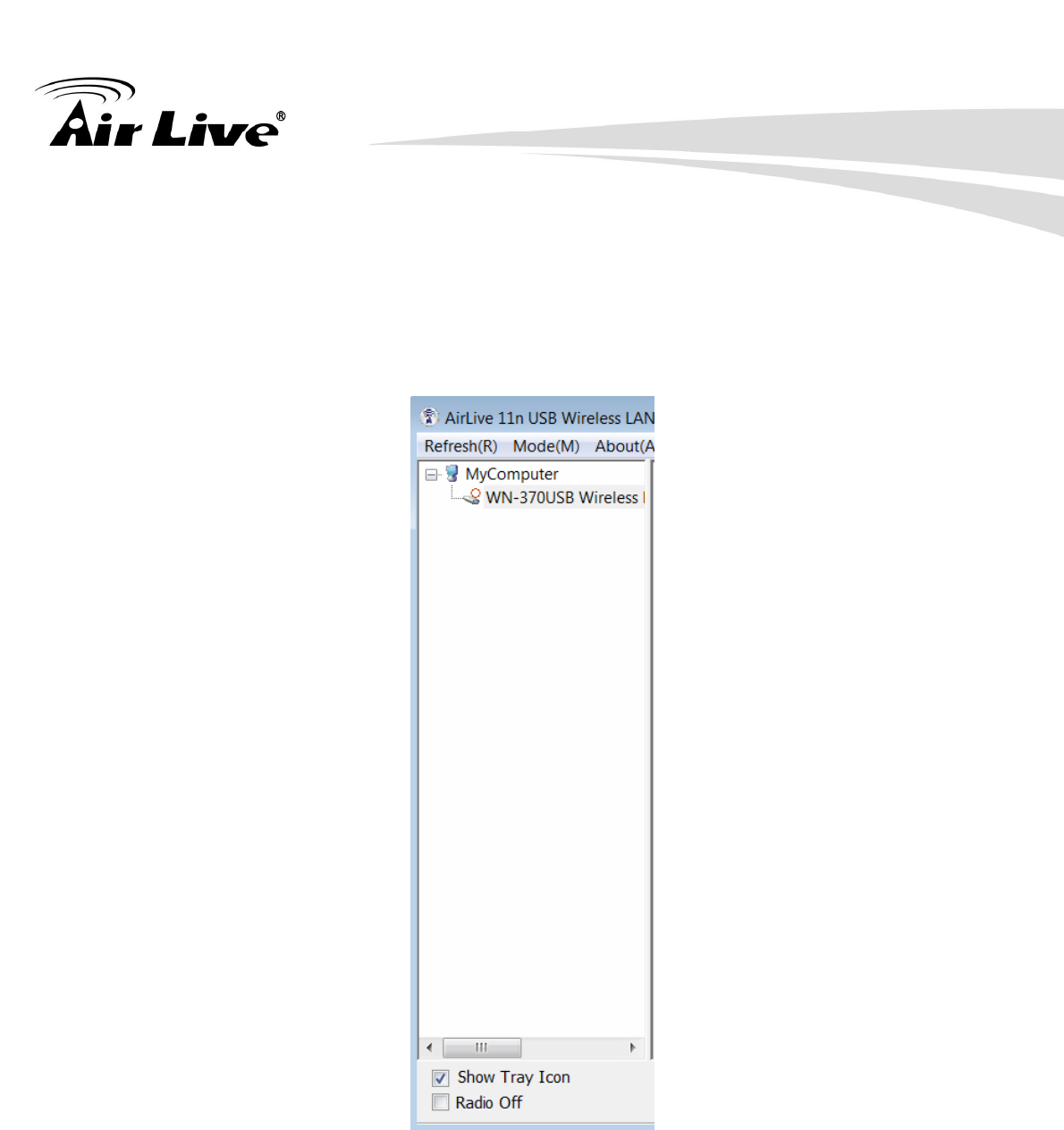
4.1 Introduction of Main Window
A. Main Menu
C. Properties Area
B. Adapter List
D. Global Control
E. Status Bar
A. Main Menu
The main menu includes five submenus.
1. Refresh(R)
When clicking the refresh menu, you can update and re-enumerate the contents of
adapter list area.
4. WLAN: Wireless LAN Management GUI
AirLive WN-370USB User’s Manual
12
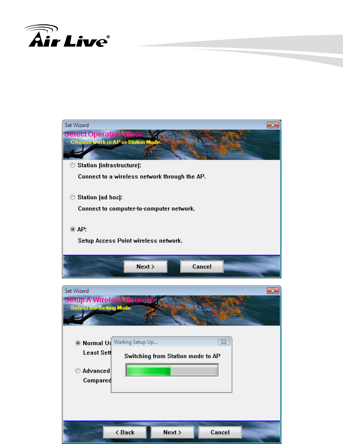
2. Set Wizard(S)
2.1 Wizard-1
Click Set Wizard(S) menu to enter operation wizard. Click AP: Setup a wireless
network.
To configure Access Point parameters—
4. WLAN: Wireless LAN Management GUI
AirLive WN-370USB User’s Manua 13
2.2 Wizard-2
User defines wireless network Name [SSID](less than 32 characters). User may
skip wireless security. Strongly recommend user to setup wireless security to
avoid invalid users.
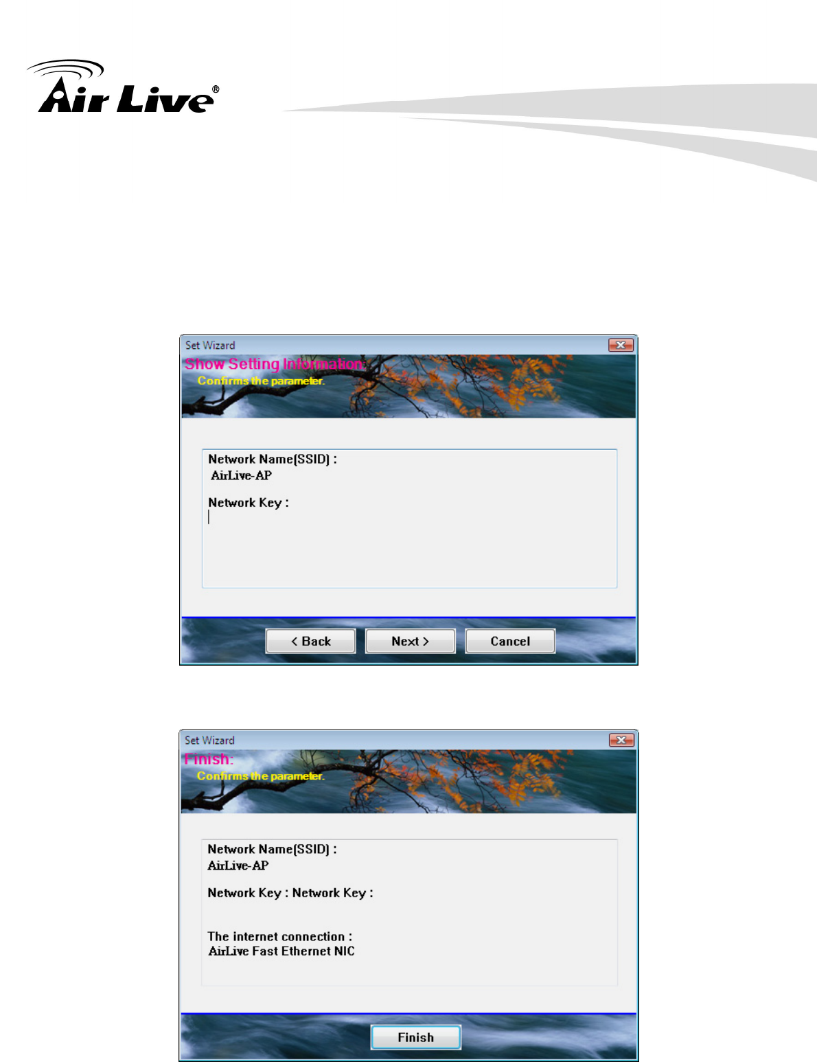
2.3 Wizard-3
This page shows SSID & Security settings.
2.4 Wizard-4
Show all settings under AP mode. Click Finish to complete wizard setup.
4. WLAN: Wireless LAN Management GUI
AirLive WN-370USB User’s Manual
14
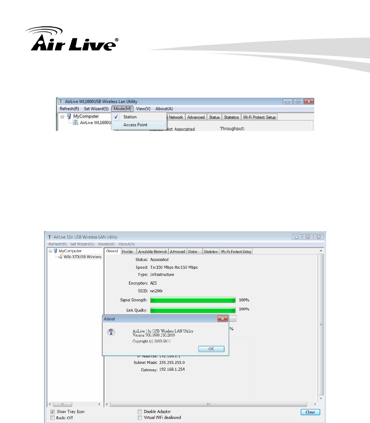
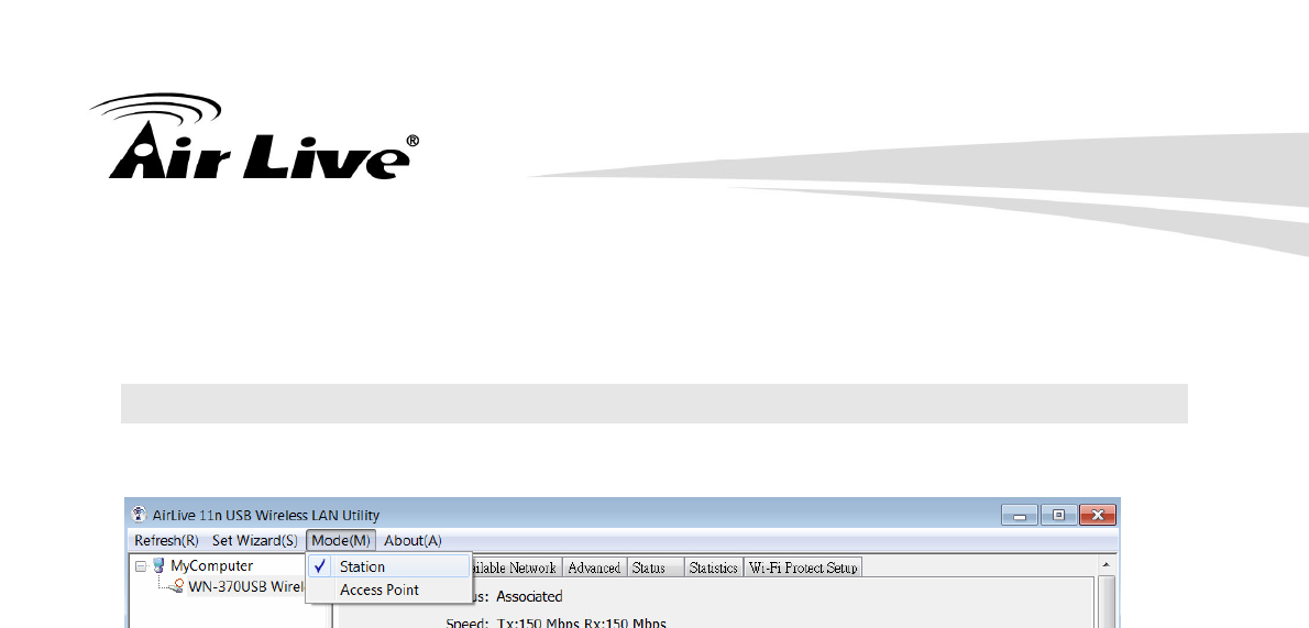
3. Mode (M)
Wireless configuration is quickly switched to either [Station] or [AP].
4. View (V)
Enable/disable the presence of E. Status Bar. Without the check mark (v) the E.
Status Bar will be hidden.
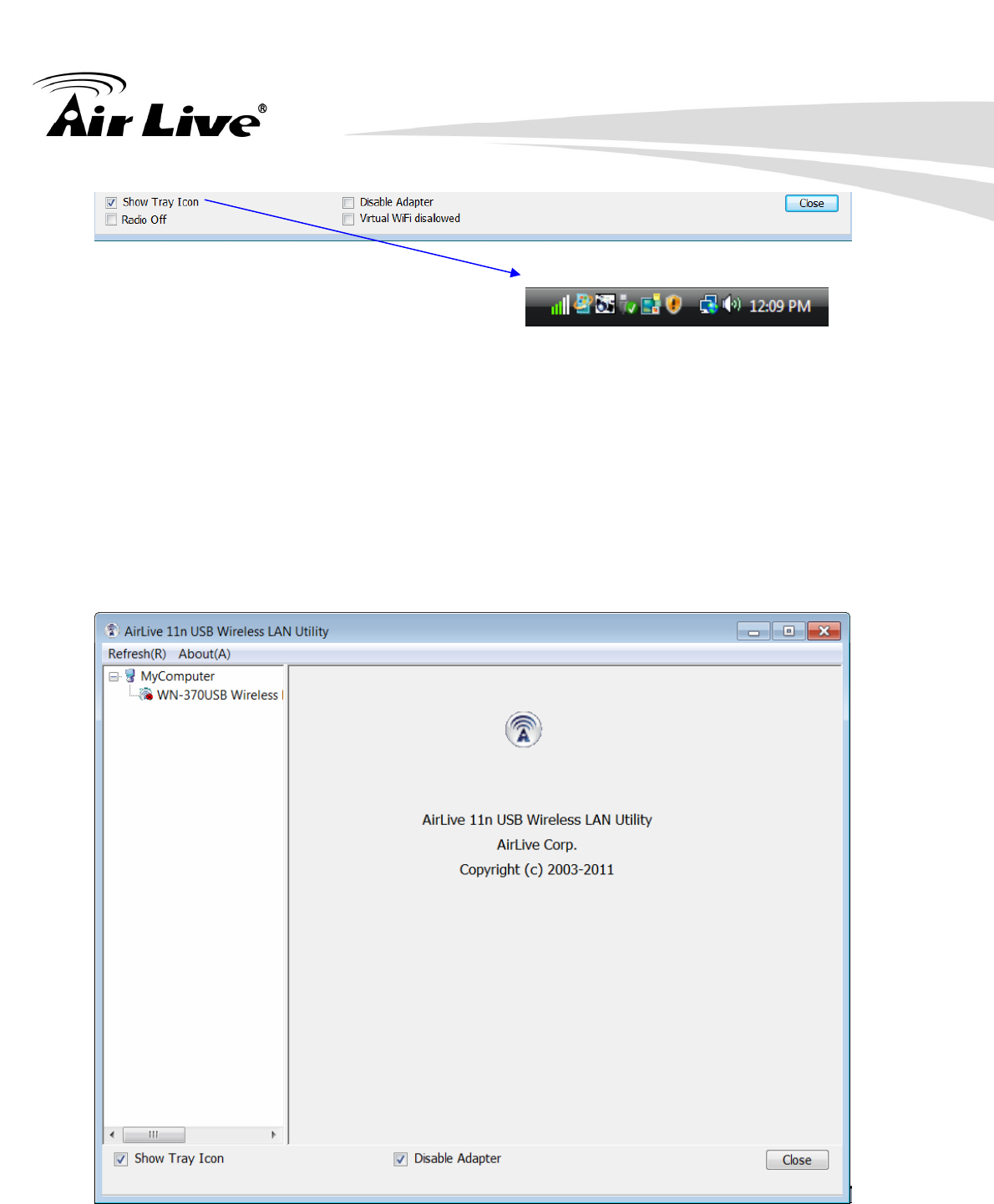
5. About (A)
Click the “About” to show the utility information dialog. The application version and
license information are shown in utility information dialog.
4. WLAN: Wireless LAN Management GUI
AirLive WN-370USB User’s Manua 15
B. Adapter List Area
All connected adapters on this system with multiple adapter installations are displayed in
this area. It is easy for users to change the selected adapter by one click. The contents of
properties area are dependant on wireless configuration that the selected adapter is set up.
If only single adapter is installed on the system, only one adapter is always selected.
4. WLAN: Wireless LAN Management GUI
AirLive WN-370USB User’s Manual
16
C. Properties Area
The contents of this area are dependent on current wireless configuration. The current
configuration is determined on previous explanation of submenu “Mode”. The more detailed
contents are described in the following wireless configuration sections for both Station and
AP mode.
D. Global Control Bar
Each control item on this bar affects the adapter or management GUI directly.
Show Tray Icon
Checking "Show Tray Icon" and clicking “Close” button, the management GUI will be
minimized and stay on the tray icon which is located at the right bottom corner of Windows.
If not, management GUI will shut down while clicking "Close" button with unchecked
condition
4. WLAN: Wireless LAN Management GUI
AirLive WN-370USB User’s Manua 17
Radio Off
Turn off the radio to save power. While the radio is off, the links with other wireless network
nodes are disconnected. User should be aware that while the wireless configuration is in
AP mode. The radio off will cause the sub network which belongs to the AP to be
disconnected with internet/intranet.
Disable Adapter
Stop wireless USB device.
4. WLAN: Wireless LAN Management GUI
AirLive WN-370USB User’s Manual
18
E. Status Bar
The hints or status of the management GUI are presented in the status bar.
4.2 Station Mode
The following explanations focus on the properties area.
Infrastructure and Ad-Hoc
With both Infrastructure and Ad-Hoc types, the properties should look like the picture above.
Six property pages present different information of current wireless network status. Please
read the following explanations before you reviewing these pages, it could help you to well
understand the wireless environment around the system. It is easy to use to switch property
pages just by clicking left button of mouse on the title of each page. The following six
sections describe detailed information of each page.
4. WLAN: Wireless LAN Management GUI
AirLive WN-370USB User’s Manua 19
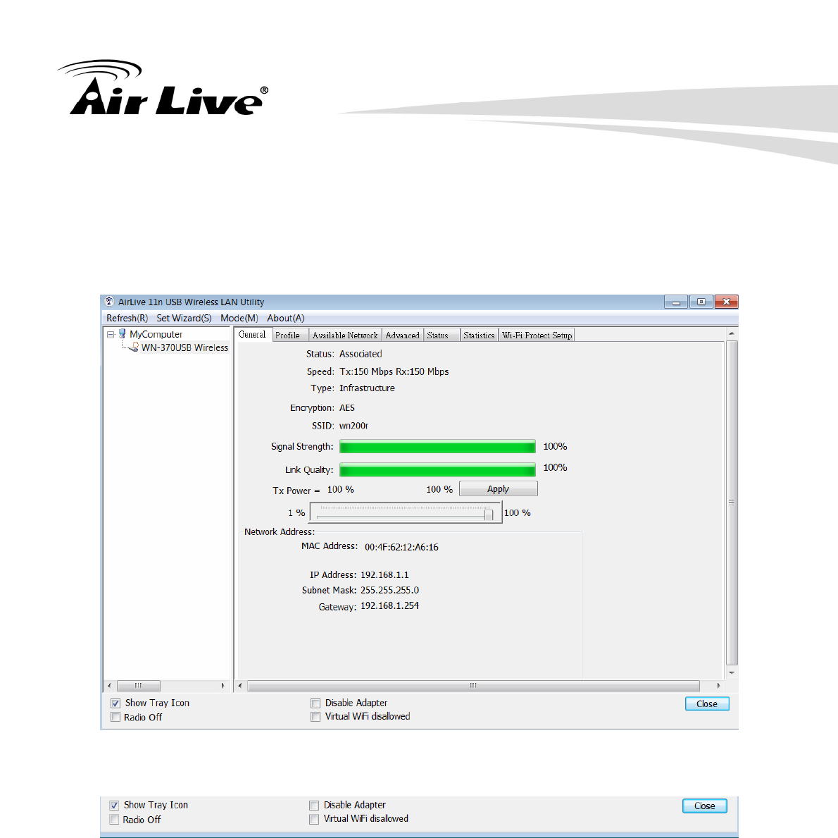
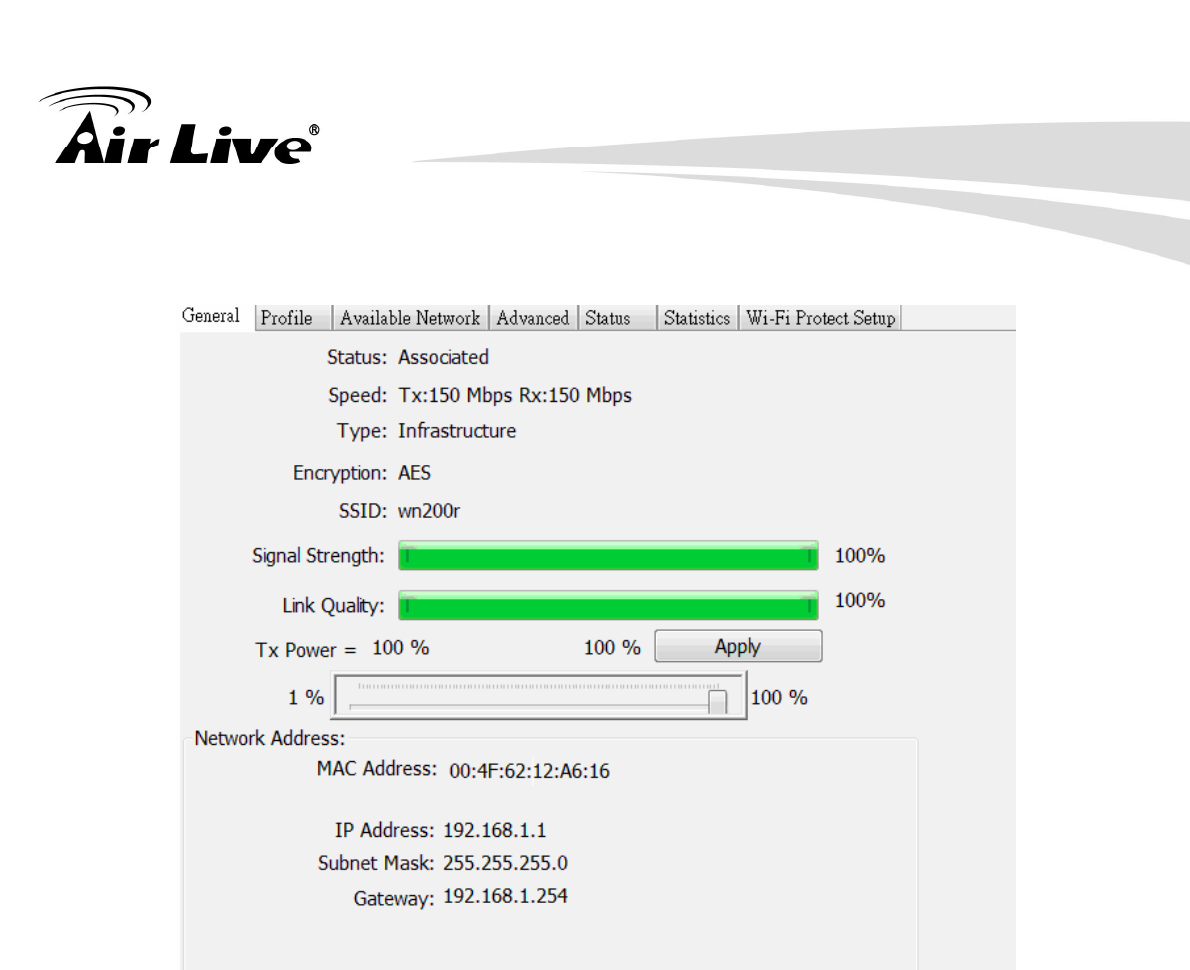
A. General Page
This page represents the general information of this adapter.
1. Status
The status of station connection to AP.
2. Speed
Current transition speed in Mbps (Mega-Bits-Per-Second).
3. Type
Current wireless LAN configuration type.
4. Encryption
Current encryption mode used.
5. SSID
Name of wireless network.
6. Signal Strength
The average signal quality of packets received from wireless network.
We recommend connecting AP with over 70% signal strength.
7. Throughput Diagram
Current throughput, including transmission (Tx) and total traffic (Total).
4. WLAN: Wireless LAN Management GUI
AirLive WN-370USB User’s Manual
20
8. Network Address
Mac Address: six two-digital number of this Wireless LAN USB adapter
IP Address: assigned network address by DHCP server or self-definition in four
three-digital number format.
■ Subnet Mask: the only valid value is 2555.255.255.0
■ Gateway: It comes from connected AP. Your system can not connect internet
with this field empty.
9. Tx Power Adjustment Shift Bar
This item can adjust the Tx power from 1 to 100 %. By the default, the Tx Power is
1%, so you may adjust this value according to your environment required.
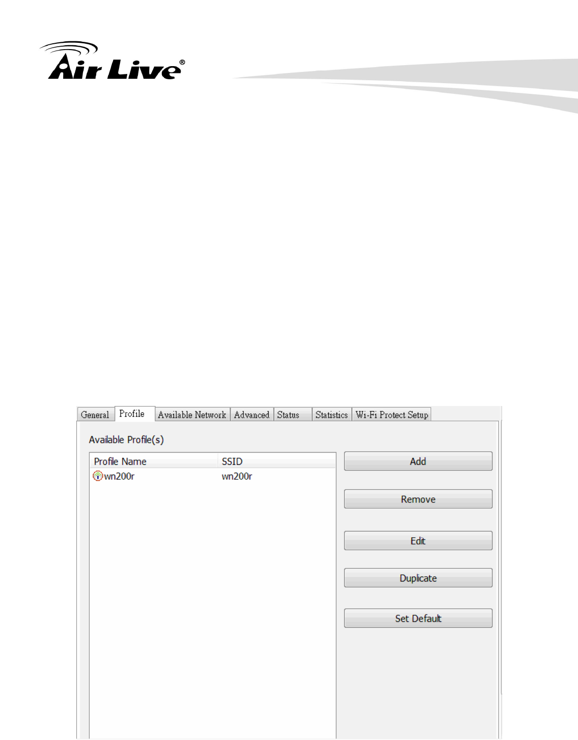
B. Profile Page
This page provides profiles management such as add, remove, edit and duplicate
just by pressing the respected button.
Available Profile(s)
The list box shows all the created profiles.
4. WLAN: Wireless LAN Management GUI
AirLive WN-370USB User’s Manua 21
1. Add
Add a new profile for AP or IBSS (Ad-Hoc mode).
2. Remove
Remove the selected profile.
3. Edit
Edit contents of selected profile.
4. Duplicate
Make copy of selected profile.
5. Set Default
Set the selected profile as default selection.
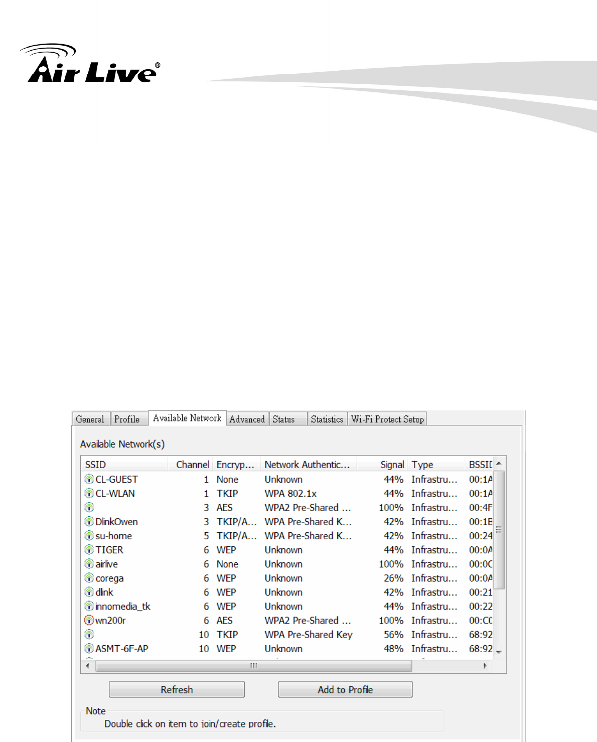
6. Available Network Page
This page presents all BSS, including AP and IBSS, around this system. You can
pick any one of these network connections.
C. Available Network(s)
Show network connection around this system

4. WLAN: Wireless LAN Management GUI
AirLive WN-370USB User’s Manual
22
1. Refresh
Rescan network connection around this system.
2. Add to Profile
Create profile for selected network connection and add it to profile list.
B. Advanced Page
1. Power Save
None: without power save function.
Min: wake up more frequently to receive packets.
Max: wake up less frequently to receive packets.
2. Wireless Mode
802.11b
802.11g/b
3. 802.11b Preamble Mode
Long: higher quality but with lower performance than preamble short mode.
Short: Normal quality but with higher performance than preamble long mode.
Auto: use the preamble mode of current.
4. WLAN: Wireless LAN Management GUI
AirLive WN-370USB User’s Manua 23
4. Fragment Threshold
The threshold of fragment length. Higher threshold increase data transition
performance with good signal quality. However, in a poor signal quality
environment, data throughput might be worse on high fragment threshold than low
fragment threshold.
5. RTS Threshold
Threshold of Request To Send mechanism. The RTS frame will not send out until
the packet size over threshold.
6. WOL (Wake On LAN)
The wake-on-LAN is applied for remote control purpose. You could wake up a
system through network packets. For Wireless LAN USB Adapter, only the same
adapter on another system could wake it up. Input MAC Address: the six two-digit
numbers of Wireless LAN USB Adapter on target system.
Wake Up: click this button to wake it up .
7. Set Defaults
Restore the default value to be current settings.
8. Apply
Apply the current settings to GUI.
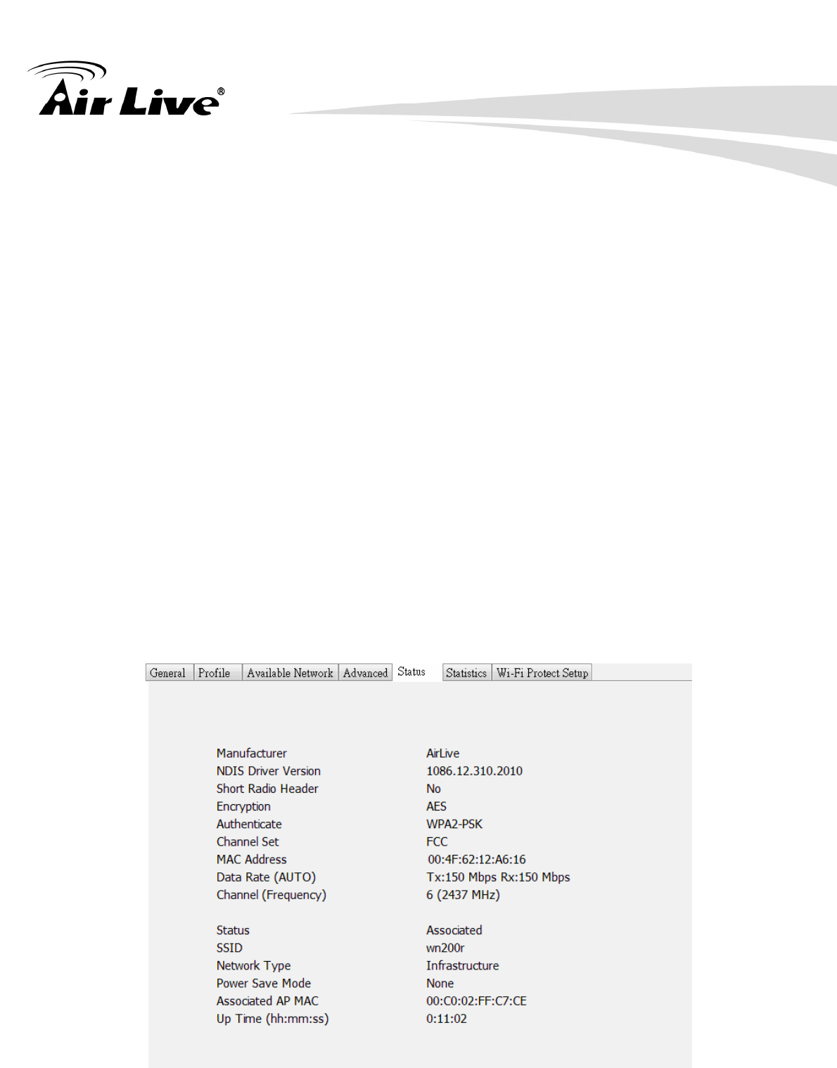
C. Status Page
4. WLAN: Wireless LAN Management GUI
AirLive WN-370USB User’s Manual
24
1. NDIS Driver Version: Driver version
2. Short Radio Header: Yes
3. Encryption: Current encryption mode.
4. Authenticate: Authentication state
5. Channel Set: Selected channel plan currently.
6. MAC Address: MAC address of this adapter.
7. Data Rate: Wireless LAN transition speed
8. Channel (Frequency): Current channel number
9. Status: Wireless network status
10. SSID: Name of connecting AP
11. Network Type: Indicate current network configuration type
12. Power Save Mode: Current setting power save mode
13. Associated AP MAC: MAC address of connecting AP
14. Up Time (hh:mm:ss): Total connection time
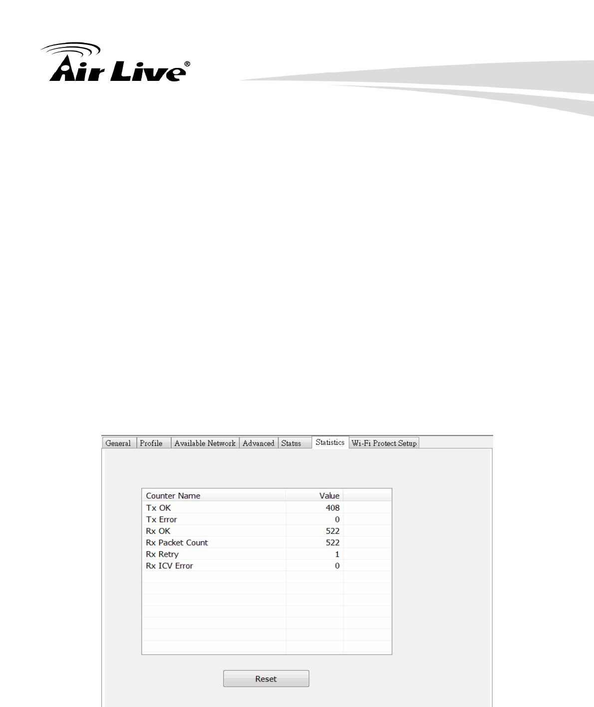
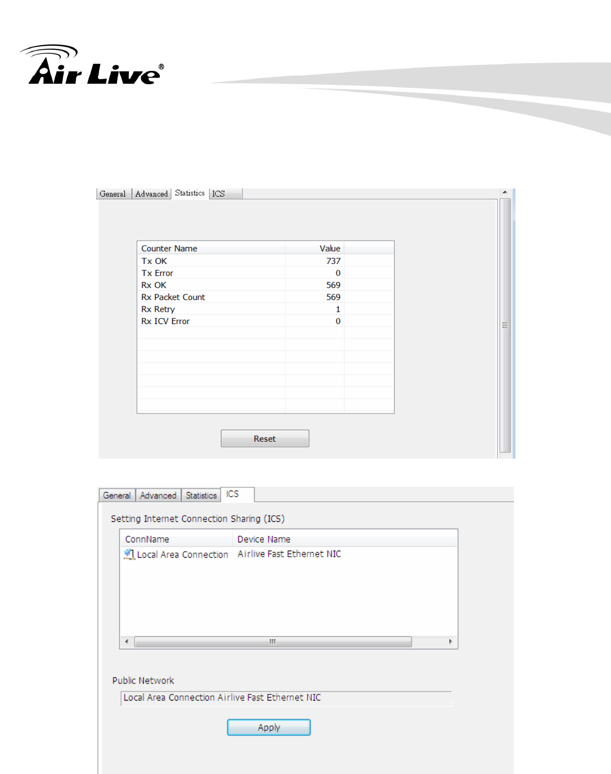
F. Statistics Page
You could watch the Tx/Rx status of current wireless connection. This page shows a
statistic analysis of packet transition.
4. WLAN: Wireless LAN Management GUI
AirLive WN-370USB User’s Manua 25
4.3 Access Point Mode
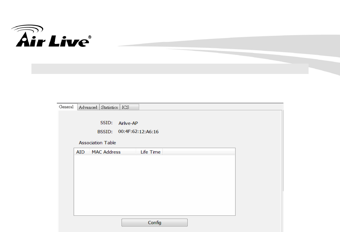
A. General Page
This page provides general information of this AP, including name, MAC address and list of
joined stations.
1. SSID
The name of this AP.
2. BSSID
Six two-digital numbers of the MAC address of this AP.
3. Association Table
It is the list of joined stations to this AP.
4. AID (Association ID)
The AID field is a value assigned by an AP during association that represents
16-bit ID of a station. It is a unique value assigned by AP.
5. MAC address
It is the six two-digit numbers that assemble the MAC address of respected joined
station.
4. WLAN: Wireless LAN Management GUI
AirLive WN-370USB User’s Manual
26
6. Life Time
It is the timer that counts down from 10 minutes whenever the AP connects the
station successfully. If an STA associated to SW AP does not have any interaction
with the AP in 10 minutes, it will be disassociated from the Infra-structure BSS.
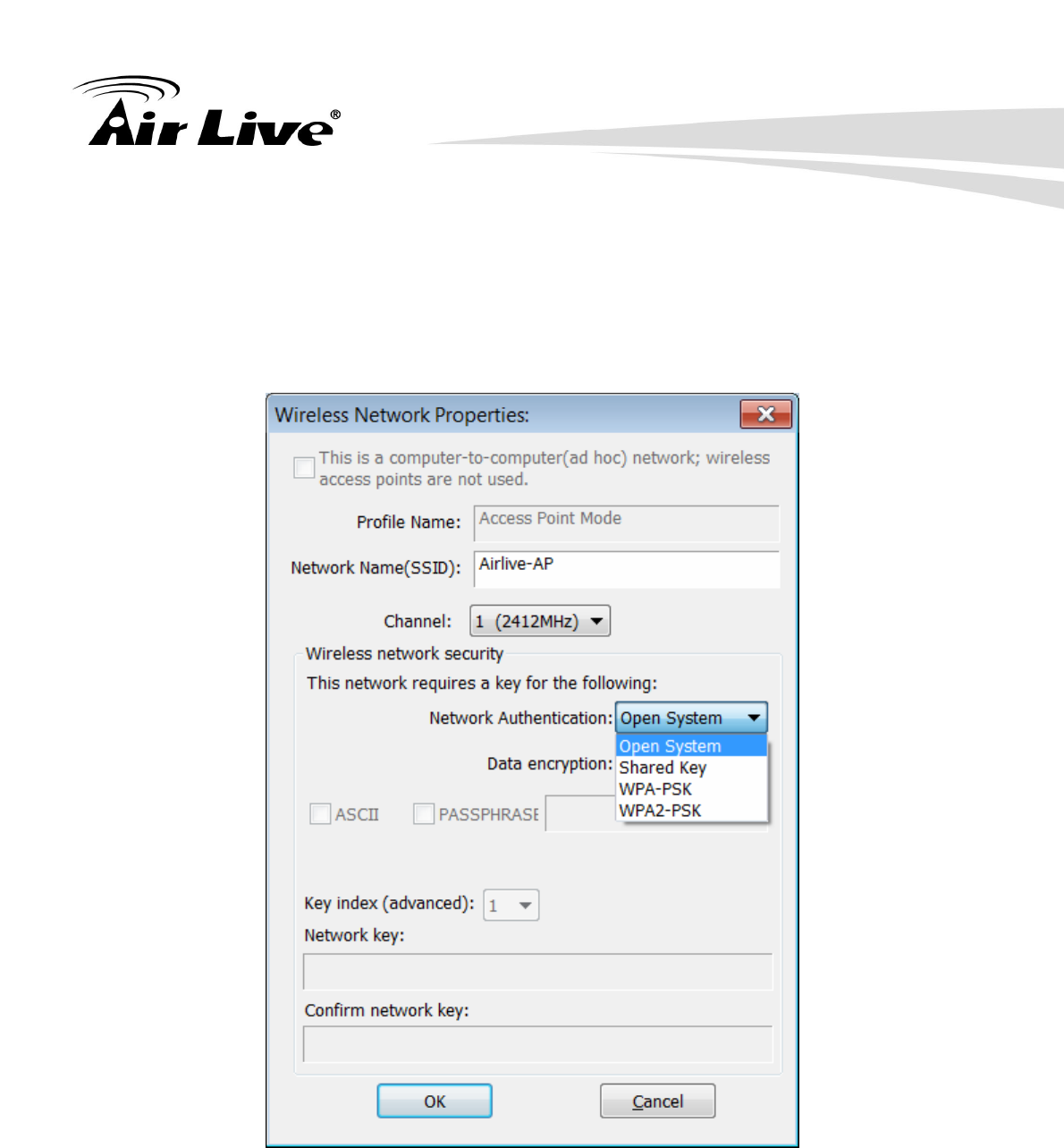
7. Configuration
A dialog of this AP is shown for configuration modification.
7.1. Network Name (SSID)
Name of the AP searchable by other wireless nodes. The length of SSID should
be shorter than 32 characters.
7.2. Channel
Select the wireless channel within current channel plan.

4. WLAN: Wireless LAN Management GUI
AirLive WN-370USB User’s Manua 27
7.3. Network Authentication & Data Encryption
There are three types of authentication:
z Open System
It is combined with data encryption type to be WEP or to be disabled.
Encryption ~ disabled: you decide to open this AP to every one without network
authentication.
Encryption ~ WEP: you decide to setup the basic data encryption with a defined
network key.
z Shared Key + WEP
You decide to apply both authentication and data encryption to prevent
unauthorized login.
z WPA-PSK + TKIP & WPA2-PSK + TKIP
The most advanced authentication and data encryption that provide the best
security protection.
7.4. ASCII/ PASSPHRASE
The most advanced authentication and data encryption that provide the best
security protection.
z ASCII: You should provide either 5 or 13 ASCII characters on Network key
edit box.
z PASSPHRASE: You could input words on Network Key edit box.
64 bits: The generated pass key is 64-bit to be complied with data packets.
128 bits: The generated pass key is 128-bit to be complied with data packets.
z Hexadecimal: While both ASCII and PASSPHRASE are not checked, you
should input hexadecimal number in the network key box. For example, 10
digits hex number for 64-bit WEP or 26 digits hex number for 128-bit WEP.
7.5. Key index (1 ~4)
At most four key index to represent the opposite network key.
4. WLAN: Wireless LAN Management GUI
AirLive WN-370USB User’s Manual
28
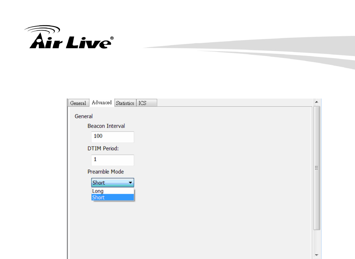
B. Advanced Page
Users could setup the advanced characteristics of network packet for transmission on this
page.
1. Beacon Interval
This filed indicates the interval between each beacon that this AP sends out in unit
of TU (1024 micro-seconds).
2. DTIM Period
The DTIM Period field is the number of Beacon intervals between successive
DTIMs.
3. Preamble Mode
z Long: higher quality but with lower performance than preamble short mode.
z Short: Normal quality but with higher performance then preamble long mode.
4. WLAN: Wireless LAN Management GUI
AirLive WN-370USB User’s Manua 29
C. Statistics Page
The Tx/Rx status of current wireless connection is shown. A statistic analysis of packet
transition is listed.
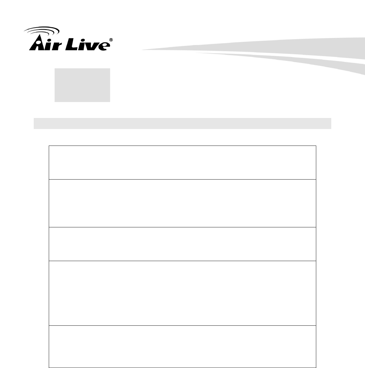
D. ICS Page

4. WLAN: Wireless LAN Management GUI
AirLive WN-370USB User’s Manual
30
1. Con Name
List all network connections to this system. You can pick up one from the listed
item(s) whose network domain you would want to connect to.
2. Apply
Execute the current settings.
5. Appendix
AirLive WN-370USB User’s Manua 31
5 5. Appendix
5.1 Troubleshooting
Q: The LED is off.
A: Make sure the PC Card is inserted properly. Otherwise contact your vendor.
Q: The LED is always on not blinking.
A: Make sure that you have installed the driver from attached CD.
Otherwise contact your vendor.
Q: The LED is blinking but the PC Card icon does not appear in your icon tray.
A: Make sure that you have installed the Utility from the attached CD.
Q: The PC Card is linking, but can’t share files with others.
A: Make sure the file and printer sharing function is enabled.
You can enable the function by checking the icon of My Computer -> Control
Panel -> Network -> file and printer sharing -> I want to be able to give
others to access to my files.
Q: Slow or poor performance under AP mode
A: Try to select another channel for the communicating group or move your
device closer to the Access Point.

5. Appendix
AirLive WN-370USB User’s Manual
32
5.2 Glossary
IEEE 802.11 Standard
The IEEE 802.11 Wireless LAN standards subcommittee, which is formulating a standard
for the industry.
Access Point
An internetworking device that seamlessly connects wired and wireless networks together.
Ad Hoc
An Ad Hoc wireless LAN is a group of computers, each with a WLAN adapter, connected as
an independent wireless LAN
Ad Hoc wireless LAN is applicable at a departmental scale for a branch or SOHO operation.
BSSID
A specific Ad Hoc LAN is called a Basic Service Set (BSS). Computers in a BSS must be
configured with the same BSSID.
DHCP
Dynamic Host Configuration Protocol - a method in which IP addresses are assigned by
server dynamically to clients on the network. DHCP is used for Dynamic IP Addressing and
requires a dedicated DHCP server on the network.
Direct Sequence Spread Spectrum
This is the method the wireless cards use to transmit data over the frequency spectrum.
The other method is frequency hopping. Direct sequence spreads the data over one
frequency range (channel) while frequency hopping jumps from one narrow frequency band
to another many times per second.
ESSID
An Infrastructure configuration could also support roaming capability for mobile workers.
More than one BSS can be configured as an Extended Service Set (ESS). Users within an
ESS could roam freely between BSSs while served as a continuous connection to the
network wireless stations and Access Points within an ESS must be configured with the
same ESSID and the same radio channel.
Ethernet
Ethernet is a 10/100Mbps network that runs over dedicated home/office wiring. Users must
be wired to the network at all times to gain access.
Gateway
A gateway is a hardware and software device that connects two dissimilar systems, such as
a LAN and a mainframe. In Internet terminology, a gateway is another name for a router.
Generally a gateway is used as a funnel for all traffic to the Internet

5. Appendix
AirLive WN-370USB User’s Manua 33
IEEE
Institute of Electrical and Electronics Engineers Infrastructure. An integrated wireless and
wired LAN is called an Infrastructure configuration. Infrastructure is applicable to enterprise
scale for wireless access to central database, or wireless
ISM Band
The FCC and their counterparts outside of the U.S. have set aside bandwidth for
unlicensed use in the so-called ISM (Industrial, Scientific and Medical) band. Spectrum in
the vicinity of 2.4 GHz, in particular, is being made available (Industrial, Scientific and
Medical) band. Spectrum in the vicinity of 2.4 GHz, in particular, is being made available of
users around the globe.
Local Area Network (LAN)
A LAN is a group of computers, each equipped with the appropriate network adapter card
connected by cable/air, that share applications, data, and peripherals. All connections are
made via cable or wireless media, but a LAN does not use telephone services. It typically
spans a single building or campus.
Network
A network is a system of computers that is connected. Data, files, and messages can be
transmitted over this network. Networks may be local or wide area networks.
Protocol
A protocol is a standardized set of rules that specify how a conversation is to take place,
including the format, timing, sequencing and/ or error checking.
SSID
A Network ID unique to a network. Only clients and Access Points that share the same
SSID are able to communicate with each other. This string is case-sensitive.
Static IP Addressing
A method of assigning IP addresses to clients on the network. In networks with Static IP
address, the network administrator manually assigns an IP address to each computer.
Once a Static IP address is assigned, a computer uses the same IP address every time it
reboots and logs on to the network, unless it is manually changed.
Temporal Key Integrity Protocol (TKIP)
The Temporal Key Integrity Protocol, pronounced tee-kip, is part of the IEEE 802.11i
encryption standard for wireless LANs. TKIP is the next generation of WEP, the Wired
Equivalency Protocol, which is used to secure 802.11 wireless LANs. TKIP provides
per-packet key mixing, a message integrity check and a re-keying mechanism, thus fixing
the flaws of WEP.

5. Appendix
AirLive WN-370USB User’s Manual
34
Transmission Control Protocol / Internet Protocol (TCP/IP)
TCP/IP is the protocol suite developed by the Advanced Research Projects Agency (ARPA).
It is widely used in corporate Internet works, because of its superior design for WANs. TCP
governs how packet is sequenced for transmission the network. The term “TCP/IP” is often
used generically to refer to the entire suite of related protocols.
Transmit / Receive
The wireless throughput in Bytes per second averaged over two seconds.
Wi-Fi Alliance
The Wi-Fi Alliance is a nonprofit international association formed in 1999 to certify
interoperability of wireless Local Area Network products based on IEEE 802.11
specification. The goal of the Wi-Fi Alliance’s members is to enhance the user experience
through product interoperability. The organization is formerly known as WECA.
Wi-Fi Protected Access (WPA)
The Wi-Fi Alliance put together WPA as a data encryption method for 802.11 wireless LANs.
WPA is an industry-supported, pre-standard version of 802.11i utilizing the Temporal Key
Integrity Protocol (TKIP), which fixes the problems of WEP, including using dynamic keys.
Wide Area Network (WAN)
A WAN consists of multiple LANs that are tied together via telephone services and / or fiber
optic cabling. WANs may span a city, a state, a country, or even the world
Wired Equivalent Privacy (WEP)
Now widely recognized as flawed, WEP was a data encryption method used to protect the
transmission between 802.11 wireless clients and APs. However, it used the same key
among all communicating devices. WEP’s problems are well-known, including an
insufficient key length and no automated method for distributing the keys. WEP can be
easily cracked in a couple of hours with off-the-shelf tools.
Wireless LAN (WLAN)
A wireless LAN does not use cable to transmit signals, but rather uses radio or infrared to
transmit packets through the air. Radio Frequency (RF) and infrared are the commonly
used types of wireless transmission. Most wireless LANs use spread spectrum technology.
It offers limited bandwidth, usually under 11Mbps, and users share the bandwidth with other
devices in the spectrum; however, users can operate a spread spectrum device without
licensing from the Federal Communications Commission (FCC).

5. Appendix
AirLive WN-370USB User’s Manua 35
Fragment Threshold
The proposed protocol uses the frame fragmentation mechanism defined in IEEE 802.11 to
achieve parallel transmissions. A large data frame is fragmented into several fragments
each of size equal to fragment threshold. By tuning the fragment threshold value, we can
get varying fragment sizes. The determination of an efficient fragment threshold is an
important issue in this scheme. If the fragment threshold is small, the overlap part of the
master and parallel transmissions is large.
This means the spatial reuse ratio of parallel transmissions is high. In contrast, with a large
fragment threshold, the overlap is small and the spatial reuse ratio is low. However high
fragment threshold leads to low fragment overhead. Hence there is a trade-off between
spatial re-use and fragment overhead. Fragment threshold is the maximum packet size
used for fragmentation. Packets larger than the size programmed in this field will be
fragmented If you find that your corrupted packets or asymmetric packet reception (all send
packets, for example). You may want to try lowering your fragmentation threshold. This will
cause packets to be broken into smaller fragments. These small fragments, if corrupted,
can be resent faster than a larger fragment. Fragmentation increases overhead, so you'll
want to keep this value as close to the maximum value as possible.
RTS (Request To Send) Threshold
The RTS threshold is the packet size at which packet transmission is governed by the
RTS/CTS transaction. The IEEE802.11-1997 standard allows for short packets to be
transmitted without RTS/CTS transactions. Each station can have a different RTS threshold.
RTS/CTS is used when the data packet size exceeds the defined RTS threshold. With the
CSMA/CA transmission mechanism, the transmitting station sends out an RTS packet to
the receiving station, and waits for the receiving station to send back a CTS (Clear to Send)
packet before sending the actual packet data. This setting is useful for networks with many
clients. With many clients, and a high network load, there will be many more collisions. By
lowering the RTS threshold, there may be fewer collisions, and performance should
improve. Basically, with a faster RTS threshold, the system can recover from problems
faster. RTS packets consume valuable bandwidth, however, so setting this value too low
will limit performance.
Beacon Interval
In addition to data frames that carry information from higher layers, 802.11 include
management and control frames that support data transfer. The beacon frame, which is a
type of management frame, provides the "heartbeat" of a wireless LAN, enabling stations to
establish and maintain communications in an orderly fashion. Beacon Interval represents
the amount of time between beacon transmissions. Before a station enters power save
mode, the station needs the beacon interval to know when to wake up to receive the
beacon (and learn whether there are buffered frames at the access point).

5. Appendix
AirLive WN-370USB User’s Manual
36
Preamble Type
There are two preamble types defined in IEEE 802.11 specification. A long preamble
basically gives the decoder more time to process the preamble. All 802.11 devices support
a long preamble. The short preamble is designed to improve efficiency (for example, for
VoIP systems). The difference between the two is in the Synchronization field. The long
preamble is 128 bits, and the short is 56 bits.
WPA2
It is the second generation of WPA. WPA2 is based on the final IEEE 802.11i amendment to
the 802.11 standard.
Temporal Key Integrity Protocol (TKIP)
The Temporal Key Integrity Protocol, pronounced tee-kip, is part of the IEEE 802.11i
encryption standard for wireless LANs. TKIP is the next generation of WEP, the Wired
Equivalency Protocol, which is used to secure 802.11 wireless LANs. TKIP provides
per-packet key mixing, a message integrity check and a re-keying mechanism, thus fixing
the flaws of WEP.
802.1x Authentication
802.1x is a framework for authenticated MAC-level access control, defines Extensible
Authentication Protocol (EAP) over LANs (WAPOL). The standard encapsulates and
leverages much of EAP, which was defined for dial-up authentication with Point-to-Point
Protocol in RFC 2284. Beyond encapsulating EAP packets, the 802.1x standard also
defines EAPOL messages that convey the shared key information critical for wireless
security.
Advanced Encryption Standard (AES)
Security issues are a major concern for wireless LANs, AES is the U.S. government’s
next-generation cryptography algorithm, which will replace DES and 3DES.
Federal Communication Commission Interference Statement
This equipment has been tested and found to comply with the limits for a Class B
digital device, pursuant to Part 15 of the FCC Rules. These limits are designed to
provide reasonable protection against harmful interference in a residential installation.
This equipment generates, uses and can radiate radio frequency energy and, if not
installed and used in accordance with the instructions, may cause harmful interference
to radio communications. However, there is no guarantee that interference will not
occur in a particular installation. If this equipment does cause harmful interference to
radio or television reception, which can be determined by turning the equipment off
and on, the user is encouraged to try to correct the interference by one of the
following measures:
. Reorient or relocate the receiving antenna.
. Increase the separation between the equipment and receiver.
. Connect the equipment into an outlet on a circuit different from that to which the
receiver is connected.
. Consult the dealer or an experienced radio/TV technician for help.
FCC Caution: To assure continued compliance, any changes or modifications not
expressly approved by the party responsible for compliance could void the user's
authority to operate this equipment. (Example - use only shielded interface cables
when connecting to computer or peripheral devices).
FCC Radiation Exposure Statement
This equipment complies with FCC RF radiation exposure limits set forth for an
uncontrolled environment. This equipment should be installed and operated with a
minimum distance of 20 centimeters between the radiator and your body.
This transmitter must not be co-located or operating in conjunction with any other
antenna or transmitter.
The antennas used for this transmitter must be installed to provide a separation
distance of at least 20 cm from all persons and must not be co-located or operating in
conjunction with any other antenna or transmitter.