Ox Co IVP-GU Wireless Gateway User Manual iVISION FIX USER MANUAL 20121115 ai
Optex Co Ltd Wireless Gateway iVISION FIX USER MANUAL 20121115 ai
Ox Co >
Users Manual
INDEX
- 1 -- 1 -
iVISION+ User Manual
1-1. Basic features of iVISION+
1-2. Expanding iVISION+ with an optional unit
2-1. Handheld Monitor Unit (IVP-HU)
2-2. Door Camera Unit (IVP-DU)
2-3. Gateway Chime Unit (IVP-GU)
3-2. How to turn ON/OFF
3-1. Getting ready with iVISION+ system
3-3. Date and Time Setting
3-5. Changing Brightness on Handheld Monitor Unit
3-4. Changing Volumes
4-1. Answering to a Door Camera Unit
4-2. Using SNAP function to capture an image
4-4. Ending ANSWER / BROWSING MODE (Returning to IDLE MODE)
4-3. Operating OPEN DOOR function
5-1. How “Auto Recording” works
5-2. Changing number of images to be captured in “Auto Recording”
5-3. Note about timings for capturing images
6-1. Viewing Images
6-3. Viewing Images from Your PC
6-2. Deleting Stored Images
7-1. Talk Switching Mode Setting
1. What you can do with iVISION+
2. Overview of iVISION+ devices
3. Before Using iVISION+
4. How to Use Basic Features
5. Auto Recording Images
6. Handling Stored Images
7. Other Settings
9. Trouble Shooting
8. Frequently Asked Questions
- 14 -
- 2 -
1. What you can do with iVISION+
1-1. Basic features of iVISION+
1-2. Expanding iVISION+ with an optional unit
iVISION+ is a wireless video intercom system with multi unit expansion capability.
When someone comes to your door and presses the button on the Door
Camera Unit (Max. 2 units), the Handheld Monitor Unit (Max. 4 units) rings a chime
and displays a video image from the camera. The Handheld Monitor Unit will store
still images if no one was there to answer the call.
Knowing who is/was at your door
Replace an old door bell with video
If you already have a door bell with 10-24VAC/DC power supplied, enable
Door Camera Unit for a browsing feature and actively view from a Handheld
Monitor Unit anytime you like. Gateway Chime Unit adds a extra chime to
let you know someone is at the door.
Operate third party equipment (e.g. Door Lock)
Connecting the OPTEX RC-20U to the iVISION+ enables “Open Door” function
to operate third party equipment connected to the output relay on RC-20U.
- 13 -
Subjects show up in black
and white or background is
a greenish color
Is the background dark, such as at night time?
• Subjects shows up as black and white due to
color-dulling when it becomes dark. Also could appear
“greenish” in areas covered by outdoor lights. This is
normal at night when lighting is provided by the IR LED
in the Door Camera Unit.
The visitors face is dark or
unclear in the video image. If the Door Camera Unit is mounted in an area with a
bright backlight (either from sunlight or outdoor lighting)
the visitor’s face may appear as a silhouette.
• Check that the camera lens is not dirty or has
condensation on the surface. Wipe with a dry cloth.
• Adjust the brightness setting (Refer to Sec. 3-5)
• Re-locate the camera to a position with no backlight.
The video image shows up
whitish or white lines or rings
show up in images.
There are small black spots
in the background of the
image.
The video image flickers.
The video image is distorted.
The voice is cut off while
answering/browsing a Door
Camera Unit.
It may be difficult to see the image if the camera lens
receives strong light such as sunlight.
• Avoid direct sunlight by re-positioning or placing a shade.
• Adjust the brightness setting (Refer to Sec. 3-5)
Does the sun show up in the image?
The center of the sun can appears as black spots if
the sun is in a view.
• Avoid direct sunlight by re-positioning or placing a shade.
• Adjust the brightness setting (Refer to Sec. 3-5)
Is a microwave oven or a wireless LAN device in operation
near to the Handheld Monitor Unit?
• Re-locate the Handheld Monitor Unit away from
such equipment.
Fluorescent lights nearby to the Camera Door Unit can
cause the image to flicker.
Symptoms Probable causes & solutions
9. Trouble Shooting
- 12 -
Symptoms
A howling noise distorts
the sound.
The ring tone cannot be
heard.
The charging does not start
when the Handheld Monitor
Unit is placed in the charging
cradle.
Probable causes & solutions
• Check battery status on Handheld Monitor Unit and
charge if necessary. Change volume setting on the
Handheld Monitor Unit. (Refer to Sec. 3-1 “Check 3”)
8. Frequently Asked Questions.
Q: Is the iVISION+ compatible to the old iVISION
A: No, but the iVISION+ is compatible with OPTEX RC-20U, which allows
the iVISION+ additional feature to operate a third-party equipment.
Q: If I connect existing door bell wires to the Door Camera Unit, will the bell still ring?
A: No. The input terminals on the Door Camera Unit are strictly for power purposes.
Please use Gateway Chime Unit to replace the existing doorbell for additional sound.
Q: Can I unload the images from the Handheld Monitor Unit to my PC?
A: Yes. micro-USB cable is required to unload images. (Refer to Sec. 6-3)
Q. What is the RF transmission range for iVISION+?
A: Signal reaches a maximum of six hundred ft (clear line of site).
RF signal condition may vary depending on surrounding environment and materials.
Q: How many Handheld Monitor Units can I have communicating to a Door Camera Unit?
A: One at a time. If another Door Camera Unit makes a call while answering, the call
will be withheld until the current session ends.
A: There is no volume adjustment for the Door Camera Unit.
Q: How can I adjust the volume on the Door Camera Unit?
If the Handheld Monitor Unit is too close to the Door
Camera unit, a howling sound can occur.
• Keep the Handheld Monitor Unit away from the Door
Camera unit.
Is the AC adaptor disconnected from the socket or the
charging cradle?
• Please check all power connections.
• Clean the charging terminals with a dry cloth.
The display on a Handheld
Monitor Unit is black and
does not respond to any key.
Is the unit in standby?
• Press any button to energize the display.
• Make sure the unit is powered on. (Refer to Sec. 3-2)
• If the battery has ran out, charge the Handheld
Monitor Unit for about 10 minutes before turning ON.
- 3 -
2. Overview of iVISION+ devices
2-1. Handheld Monitor Unit (IVP-HU)
LEFT key
RIGHT key
OPEN DOOR
PLAY
DOWN
UP
SNAP
BROWSE
ANSWER
OFF
BRIGHTNESS
Monitor Screen / Status Indicator
IMAGE VIEWING MODE
IDLE MODE
Please make sure that all the Handheld Monitor Units are on cradles and being charged while
they are in their idle mode. Intercom sound may be unstable due to different locations having
different radio transmission environments.
Monitor Screen shows video image from Door Camera
Unit when, PUSH button on the IVP-DU is pressed.
Status Indicator appears for 10 sec when any button
is pressed.
Current Date & Time
BROWSING MODE
Handheld Monitor Unit battery status
Device ID (from 1 - 4)
Current Date & Time
Door Camera Unit Low Battery Indicator
Door Camera Unit Number (1 or 2)
Handheld Monitor Unit battery status
Signal status
Door Camera Unit Number (1 or 2)
Captured Date & Time of viewing image
Number / Number of stored images
Used for confirmation of a command that appears
on the lower left of the screen.
Press and hold for 2 sec to enter into
SYSTEM SETUP menu.
(Push to talk in “Manual”Talk Switching Mode)
Used for confirmation of a command that appears
on the lower right of the screen.
Enabled only when a third party Electronic Door
Lock is connected to iVISION+ system via
OPTEX RC-20U unit.
Select DOOR1 or DOOR 2 to activate
output relay on designated RC-20U Unit.
Press to answer a call from Door Camera Unit
Press to terminate a session. Lights when charging.
Press and hold for 2 sec to ON/OFF the device.
Unit 1 must remain “ON” for automatic
recording function to be enabled.
Press to capture an image while answering
a call or when browsing a Door Camera Unit.
IDLE MODE: Select a volume of a ring tone
< >
While Answer or Browse: Select a volume
< >
IDLE MODE: Press to enter IMAGE VIEWING MODE
Press and hold for 2 sec to delete all stored images.
While Answer or Browse: Press to set brightness
< >
IDLE MODE: Press to enter BROWSING MODE
Select Door 1 or Door 2 to view.
Enabled only when Door Camera Unit is
powered from an external power source.
- 4 -
2-2. Door Camera Unit (IVP-DU)
2-3. Gateway Chime Unit (IVP-GU)
Camera Module with IR LEDs
Auto Day and Night(IR) Vision enables
color images in daytime and
black & white images when dark.
MICROPHONE
PUSH button
The button glows with fluorescence
after dark. If the unit is supplied with
external power, the button stays
illuminated.
The Door Camera Unit is a device that makes a call to the Handheld Monitor Units (IVP-HU) when
the push button is pressed by a visitor. Each iVISION+ system can carry up to 2 units of
Door Camera Units and each is identified by or on Handheld Monitor Units.
Please replace the batteries when Handheld Monitor Units show a low battery status indicator
on upper middle of the screen. The sign indicates that Door Camera Unit has low power supply
from current 3 AA batteries.
The Gateway Chime Unit is a chime device for the iVISION+ and is required when expanding with
OPTEXRC-20U. The unit enables the “Open door” function.
Sound ON/OFF Switch
This switch is for turning
ON/OFF a speaker module.
The Gateway Chime Unit remains
ON while power is being supplied.
Do not mix oldandnewbatteriesorlithiumandalkalinebatteries in this unit.
Leakageorpossibleexplosion can occur and may lead to severe damage or injuries.
Caution
- 11 -
7. Other Settings
7-1. Talk Switching Mode Setting
SYSTEM SETUP
1 DATE & TIME
2 SYSTEM CONFIGURATION
3 DEVICES IN NETWORK
4 PC CONNECTION
OK BACK
SYSTEM CONFIGURATION
1 NUMBER OF CAPTURING IMAGE
2 TALK SWITCHING MODE
OK BACK
TALK SWITCHING SETUP
PRESS UP OR DOWN KEY TO SET UP
2 AUTO(LOW NOISE)
3 AUTO(MIDDLE NOISE)
4 AUTO(HIGH NOISE)
OK BACK
1 MANUAL
(1)Enter SYSTEM SETUP menu buy pressing LEFT function
key for more than 2 seconds.
By default, Talk Switching Mode between a Door Camera Unit
and a Handheld Monitor Unit is set to AUTO(MIDDLE NOISE).
This means that a conversation switches automatically from
a listener to a speaker on either side of the intercom when
an unit is picking up a voice or any relevant sound.
If you wish to change the setting please take following
procedures.
(2)Select “2 TALK SWITCHING MODE” by using UP and
DOWN keys and press LEFT function key to confirm “OK”
(3) In TALK SWITCHING SETUP screen, select a mode from 1 to
4 by usingUP and DOWN keys and press LEFT function
key to confirm “OK”.
1 MANUAL
2 AUTO(LOW NOISE)
3 AUTO(MIDDLE NOISE)
4 AUTO(HIGH NOISE)
This is a “Push to talk” mode. Door Camera Unit only receives a voice or
a sound from a Handheld Monitor Unit when LEFT function key is being
pressed. Use this mode to avoid unwanted sound from the house to be
heard from a Door Camera Unit.
Listener and speaker side switches automatically in this mode. Use this
in a very quiet and low noise environment to enhance conversational
responses.
Listener and speaker side switches automatically in this mode. This is
a default factory setting.
Listener and speaker side switches automatically in this mode. Use this
with a noisy environment to enhance conversational responses.
Press LEFT function key
to speak to a Door Camera Unit
when in MANUAL setting.
- 5 -
3. Before Using iVISION+
3-2. How to ON/OFF the system.
3-1. Getting ready with iVISION+ system
Before using iVISION+ system, the system must be installed accordingly
to individual Installation Instruction. Once the installation is done, please
make sure that each Handheld Monitor Unit is fully charged on a cradle.
The OFF button lights up while charging until fully charged.
To check number of iVISION+ devices in your system, press and hold
LEFT function key for 2 sec to bring upa SYSTEM SETUP menu.
Select “3 DEVICES IN NETWORK” by DOWN button and confirm OK.
Pressing down the “OFF” button for more than 3 seconds,
will turn ON/OFF the Handheld Monitor Unit.
Identify the Main Handheld Unit by an indicator on a screen.
The main handheld unit is the unit that captures and stores images
while “Auto Recording Function”is activated.
The main unit must stay turned ON for the “Auto Recording Function”
CHECK 1: Handheld Monitor Unit needs be charged before usage.
CHECK 2: Confirm devices registered in the system
CHECK 3: Identify the Main Handheld Unit
CHECK 4: Select a chime volume from the Handheld Monitor Unit
While in IDLE MODE, Use UP and DOWN keys to select a chime volume for
each Handheld Monitor Unit in the iVISION+ system.
At least one paired Handheld Monitor Unit needs to stay turned
“ON” to respond to a call from the external Door Camera Unit.
When the main Handheld Monitor Unit is turned off,
the iVISION+ does not have the auto recording feature enabled.
This indicator shows battery status on the Handheld Monitor Unit.
SYSTEM SETUP
1 DATE & TIME
2 SYSTEM CONFIGURATION
3 DEVICES IN NETWORK
4 PC CONNECTION
OK BACK
IDLE MODE
IDLE MODE
This indicator No. 1 is shown on the main unit. 2,3 & 4 are sub units.
< < < <
MUTE MAX
Caution
Installation Instruction of Handheld Monitor Unit
[7-1 Confirming number of iVISION+ devices in a HOME ID]
REFERENCE
- 10 -
6. Handling Stored Images
6-1. Viewing Images
6-3. Viewing Images from Your PC
6-2. Deleting Stored Images
(1) While in IDLE MODE, press PLAY to enter
IMAGE VIEWING MODE
DELETE ALL IMAGES?
OK BACK
DELETE
(2)Use UP and DOWN keys to browse through stored
images.
(3)End IMAGE VIEWING MODE by pressing OFF button.
(1) While in IMAGE VIEWING MODE, select image to delete
by UP and DOWN keys.
Deleting selected images in a memory
(2) Press RIGHT function key to delete the image.
Deleting all images stored in a memory
(1) While in IDLE MODE, press and hold PLAY button
for more than 2 seconds.
(2) If OK, press LEFT function key to delete all images.
Please note that once images are deleted, they can not be restored.
CAUTION
CONNECT TO PC ?
OK BACK
(1) Enter SYSTEM SETUP menu by pressing LEFT function
key for more than 2 seconds.
(2) Select “4 PC CONNECTION” by using UP and
DOWN keys. Confirm “OK” by LEFT function key.
Make sure that the Handheld Monitor Unit is connected
to a PC by micro-USB cable*1. and proceed with “OK” by
pressing LEFT function key. PC CONNECTION MODE
will start.
(3)
*1micro-USB cable must be obtained separately from available electronics shops
(4) Your PC will recognize the Handheld Monitor Unit as
an external storage device. Access the device to retrieve
or manage stored image files*2.
(5) Eject the storage device from the PC and confirm “BACK”
by RIGHT function key to return to IDLE MODE.
*2PC may require addition procedures to recognize the unit. Supported Window 7 or a later version.
- 6 -
3-3. Date and Time Setting
Please enter SYSTEM SETUP menu by pressing down on LEFT function key for more
than 2 seconds. (Changes in SETUP can only be made on HU1)
3-5. Changing Brightness on Handheld Monitor Unit
SYSTEM SETUP
1 DATE & TIME
2 SYSTEM CONFIGURATION
3 DEVICES IN NETWORK
4 PC CONNECTION
OK BACK
Select “1 DATE & TIME” by using UP and DOWN keys
and press LEFT function key to confirm “OK”
Within a DATE & TIME SETUP mode:
UseUP and DOWN keys to increase / decrease a value
Press PLAY to move to the next field.
DATE & TIME SETUP
20XX / XX / XX 11 : 59 AM
OK BACK Complete the setup with OK.
3-4. Changing Volumes
Pressing Up and DOWN keys while on idle changes volume of
the chime that ring out from the Handheld Monitor Units.
IDLE MODE
ANSWERING/BROWSING
Pressing Up and DOWN keys while answering a call or browsing
changes volume of the sound out from the Handheld Monitor Units.
While in Answer or Browsing mode, Click on Brightness to shift
brightness of the screen. Brightness changes in 5 steps and repeats.
Brighter
Dimmer
- 9 -
5. Auto Recording Images
5-1. How “Auto Recording” works
5-2. Changing number of images to be captured in “ Auto Recording”
Every time Door Camera Unit makes a call to a main Handheld
Monitor Unit, HU1 will capture images from the screen
and stores into its internal memory.
If you wish to disable the Auto Recording function, please follow
step 5-2 as described in the next section. Set number of images
to be captured to “0” zero.
The internal memory of the Main Handheld Monitor Unit can store
up to 500 images. If any exceeding number of images are to be
captured, oldest pictures are deleted and overwritten immediately.
When the Handheld Monitor Unit has newly captured images
from Auto Recording, PLAY button will be blinking.
By default, the number of images to be captured during Auto
Recording is “2” two.
!
SYSTEM SETUP
1 DATE & TIME
2 SYSTEM CONFIGURATION
3 DEVICES IN NETWORK
4 PC CONNECTION
OK BACK
NOTE
Please enter SYSTEM SETUP menu by pressing down on
LEFT function key for more than 2 seconds.
Select “2 SYSTEM CONFIGURATION” by using UP and
DOWN keys and press LEFT function key to confirm “OK”
SYSTEM CONFIGURATION
1 NUMBER OF CAPTURING IMAGE
2 TALK SWITCHING MODE
OK BACK
PRESS UP OR DOWN KEY TO SET UP
NUMBER OF CAPTURING IMAGE: 2
OK BACK
Select “1 NUMBER OF CAPTURING IMAGE” and press
LEFT function key to confirm “OK”
UsingUP and DOWN keys, select the number of images
to be captured during “Auto Recording” from “0” zero
to “10” ten.
Please press LEFT Function key to “OK” your selection. The
screen will consequently return to IDLE MODE.
5-3. Note about timings for capturing images.
!
First image will be captured within a second after the PUSH button on the
Door Camera Unit is pressed. The second image will be captured 3 seconds
after the first image. The third and the following images will be captured
after intervals of 2 second in between.
(1)
(2)
(3)
(4)
(5)
- 8 -
4-2. Using SNAP function to capture an image
4-4. Ending a ANSWER / BROWSING MODE (Returning to IDLE MODE)
During ANSWER or BROWSING MODE, press SNAP to record
a still image from the Door Camera Unit. An REC Indicator in red
will appear on the top of the screen for 1 second.
Press OFF button to terminate ANSWER or BROWSING MODE
and return to IDLE MODE.
4-3. Operating OPEN DOOR function
the Handheld Monitor Unit can capture an image from a Door
Camera Unit and stores up to 500 images in an internal memory.
REC Indicator
OPEN DOOR function is only available if iVISION+ system is expanded with
an OPTEX RC-20U Unit through a Gateway Chime Unit.
OPEN DOOR
DOOR1 DOOR2
Pressing OPEN DOOR button will bring an OPEN DOOR menu
on the screen. Select DOOR1 or DOOR2 to activate a designated
output relay on RC-20U unit. Two short beeps will confirm the
signal transmission. Return to IDLE mode by pressing OFF.
IDLE MODE
During ANSWER or BROWSE mode
Pressing OPEN DOOR button while answering a call or
browsing directly activates the RC-20U output relay designated
to a Door Camera Unit. This is indicated on the top of the screen.
ANSWER/BROWSING MODE
Indicator for a Door Camera Unit in operation
Pressing OFF button for more than 2 seconds will turn off the
power of the Handheld Monitor Unit. When the power is turned
off the unit will not respond to a call from a Door Camera Unit.
CAUTION
CAUTION
- 7 -
4. How to Use Basic Features
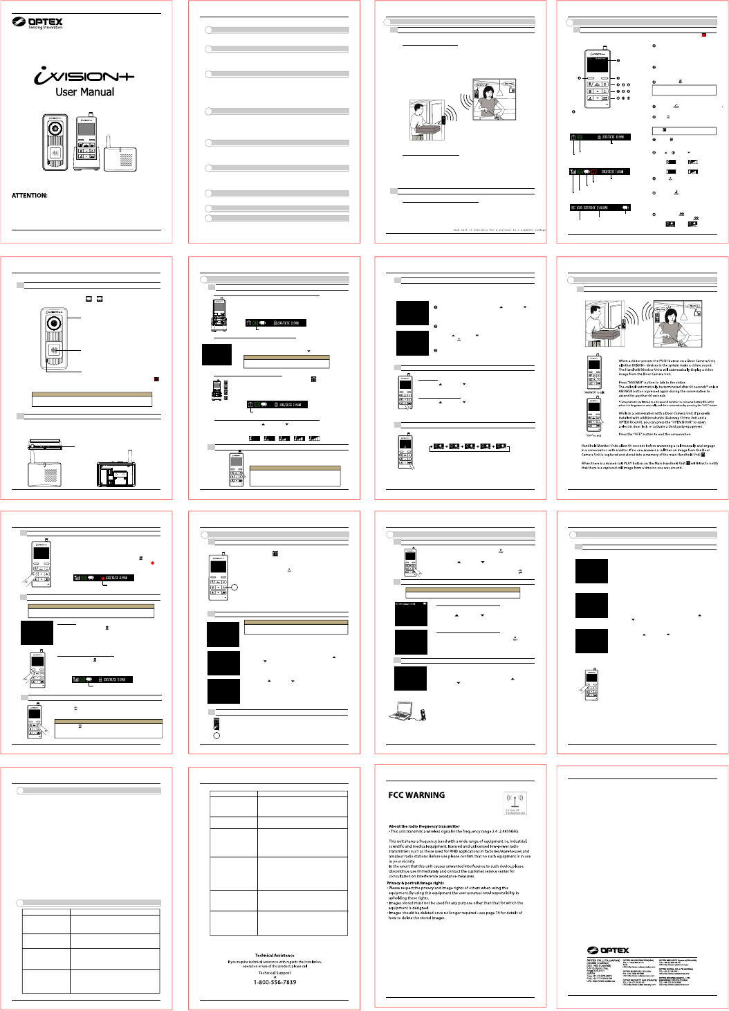
4-1. Answering to a Door Camera Unit
(1)
(2)
(3)
(4)
Wireless Video Intercom
Thank you for purchasing the iVISION+ wireless video intercom.
Due to the nature of radio frequency transmission technology, the transmission range,
stability of images, video and sound of the iVISION+ can not be guaranteed at all times.
Performance of this product depends on the environment where the product is being used.
Please carefully read all included documents and test for feasibility before applying
any damages to the installation environment. Keep documents safe for future reference.
3 DOOR OPEN DURATION SETUP
FCC StatementsFCC StatementsFCC StatementsFCC StatementsFCC StatementsFCC StatementsFCC Statements
Any Changes or modifications not expressly approved by the party responsible for compliance could void the user’s authority to
This device complies with part 15 of the FCC Rules. Operation is subject to the following two conditions: (1) This device may not
cause harmful interference, and (2) this device must accept any interference received, including interference that may cause
undesired operation.
operate the equipment.
FCC Radiation Exposure Statement
This equipment complies with FCC radiation exposure limits set forth for an uncontrolled environment.
This transmitter must not be co-located or operating in conjunction with any other antenna or transmitter.
FCC Radiation Exposure StatementFCC Radiation Exposure Statement
Note: This equipment has been tested and found to comply with the limits for a Class B digital device, pursuant to part 15
of the FCC Rules. These limits are designed to provide reasonable protection against harmful interference in a
residential installation. This equipment generates uses and can radiate radio frequency energy and, if not installed and
used in accordance with the instructions, may cause harmful interference to radio communications.
However, there is no guarantee that interference will not occur in a particular installation. If this equipment does cause
harmful interference to radio or television reception, which can be determined by turning the equipment off and on,
the user is encouraged to try to correct the interference by one or more of the following measures:
—Reorient or relocate the receiving antenna.
—Increase the separation between the equipment and receiver.
—Connect the equipment into an outlet on a circuit different from that to which the receiver is connected.
—Consult the dealer or an experienced radio/TV technician for help.
IC StatementsIC Statements
This device complies with Industry Canada licence-exempt RSS standard (s). Operation is subject to the following two conditions:
(1) this device may not cause interference, and (2) this device must accept any interference,including interference that may cause
undesired operation of the device.
Le présent appareil est conforme aux CNR d'Industrie Canada applicables aux appareils radio exempts de licence.
L'exploitation est autorisée aux deux conditions suivantes:
(1) l'appareil ne doit pas produire de brouillage, et
(2) l'utilisateur de l'appareil doit accepter tout brouillage radioélectrique subi, même si le brouillage est susceptible d'en
compromettre le fonctionnement.
Under Industry Canada regulations, this radio transmitter may only operate using an antenna of a type and maximum (or lesser)
gain approved for the transmitter by Industry Canada. To reduce potential radio interference to other users, the antenna type
and its gain should be so chosen that, the equivalent isotropically radiated power (e.i.r.p.) is not more than that
necessary for successful communication.
Conformément à la réglementation d'Industrie Canada, le présent émetteur radio peut fonctionner avec une antenne d'un type et
d'un gain maximal (ou inférieur) approuvé pour l'émetteur par Industrie Canada. Dans le but de réduire les risques de
brouillage radioélectrique à l'intention des autres utilisateurs, il faut choisir le type d'antenne et son gain de
sorte que la puissance isotrope rayonnée équivalente (p.i.r.e.) ne dépasse pas l'intensité nécessaire à l'établissement d'une
communication satisfaisante.
This radio transmitter (identify the device by certification number, or model number if Category II) has been approved by Industry
Canada to operate with the antenna types listed below with the maximum permissible gain and required antenna impedance for each
antenna type indicated. Antenna types not included in this list, having a gain greater than the maximum gain indicated for that
type, are strictly prohibited for use with this device.
Le présent émetteur radio (identifier le dispositif par son numéro de certification ou son numéro de modèle s'il fait partie du matériel
de catégorie I) a été approuvé par Industrie Canada pour fonctionner avec les types d'antenne énumérés ci-dessous et ayant un
gain admissible maximal etl'impédance requise pour chaque type d'antenne. Les types d'antenne non inclus dans cette liste,
ou dont le gain est supérieur au gain maximal indiqué, sont strictement interdits pour l'exploitation de l'émetteur.
IC Radiation Exposure StatementIC Radiation Exposure Statement
This equipment complies with IC RF radiation exposure limits set forth for an uncontrolled environment. This transmitter must not
be co-located or operating in conjunction with any other antenna or transmitter.
IC exposition aux radiations:
Cet équipement est conforme avec IC les limites d'exposition aux rayonnements définies pour un contr?lé environnement.
Cet émetteur ne doit pas être co-localisés ou fonctionner en conjonction avec une autre antenne ou émetteur.
This transmitter (IVP-DU&IVP-GU) should be installed and operated with minimum distance 20cm between the radiator
& your body.
This transmitter (IVP-DU&IVP-GU) should be installed and operated with minimum distance 20cm between the radiator
& your body.
Cet émetteur (IVP-DU & IVP-GU) doit être installé et utilisé à distance minimum de 20cm entre le radiateur et votre corps.