User manual

1000
12
1
3
12
1
312
1
312
1
312
1
3
TR-10U REPEATER
This product is only compatible with the Wireless 1000 series.
TR-10U MANUAL
Please read this manual carefully before installation.
FEATURES
• Compatible with the TD-10U (In/Outdoor Sensor Transmitter), the TS-10U (Handheld Transmitter),
TC-10U (Door/Window Transmitter), RC-10U (Chime Box W/Relay), RG-10U (Single Relay
Receiver)
• Identifies the zone (location) by LED lights (4 channel)
• A total of 4 transmitters can be learned
• Preset transmission codes are automatically “learned” by the repeater
• Over 8 million codes possible, eliminates interference from neighbors
• Push button switches to select the function settings
• Low battery indicator
• Powered by a 9VAC adaptor (included)
CAUTION
Please be careful of the following:
1. Do not use outside.
This product is not supposed to use outside of the building.
2. High Temperature, High humidity & Dirty Fumes
Do not expose the TR-10U to high temperature changes, rapid changes in temperature,
steam, high humidity or oily smoke.
3. Transmission range may decrease under the following conditions:
• A steel door, reinforced concrete, or other metal obstructions between the transmitter and
TR-10U and the receiver.
• Installing either the transmitter or TR-10U or the receiver on a metal surface.
• Places near strong radio sources, such as broadcast stations or high power lines.
• To comply with the FCC RF exposure compliance requirements, this device and its antenna
must not be co-located or operating in conjunction with any other antenna or transmitter.
4. Other Electric Devices
Use the TR-10U at least 3ft (1m) away from following devices: TV, radio, personal
computer, microwave oven, refrigerator, and any device that has an electric motor
(This may cause malfunction).
5. Impact/Shock
Do not drop or impact the TR-10U in any manner.
6. Tampering
Do not change or modify the products without approval from a professional engineer
or electrician. Manufacturer can not accept responsibility for any accidents.
7. Cleaning
Harsh cleaners such as paint removers or benzene may ruin the surface. Use a soft,
wet cloth and mild soap or detergent to clean.
8. Adaptor
Do not use any other AC adaptor except including one.
INSTALLATION
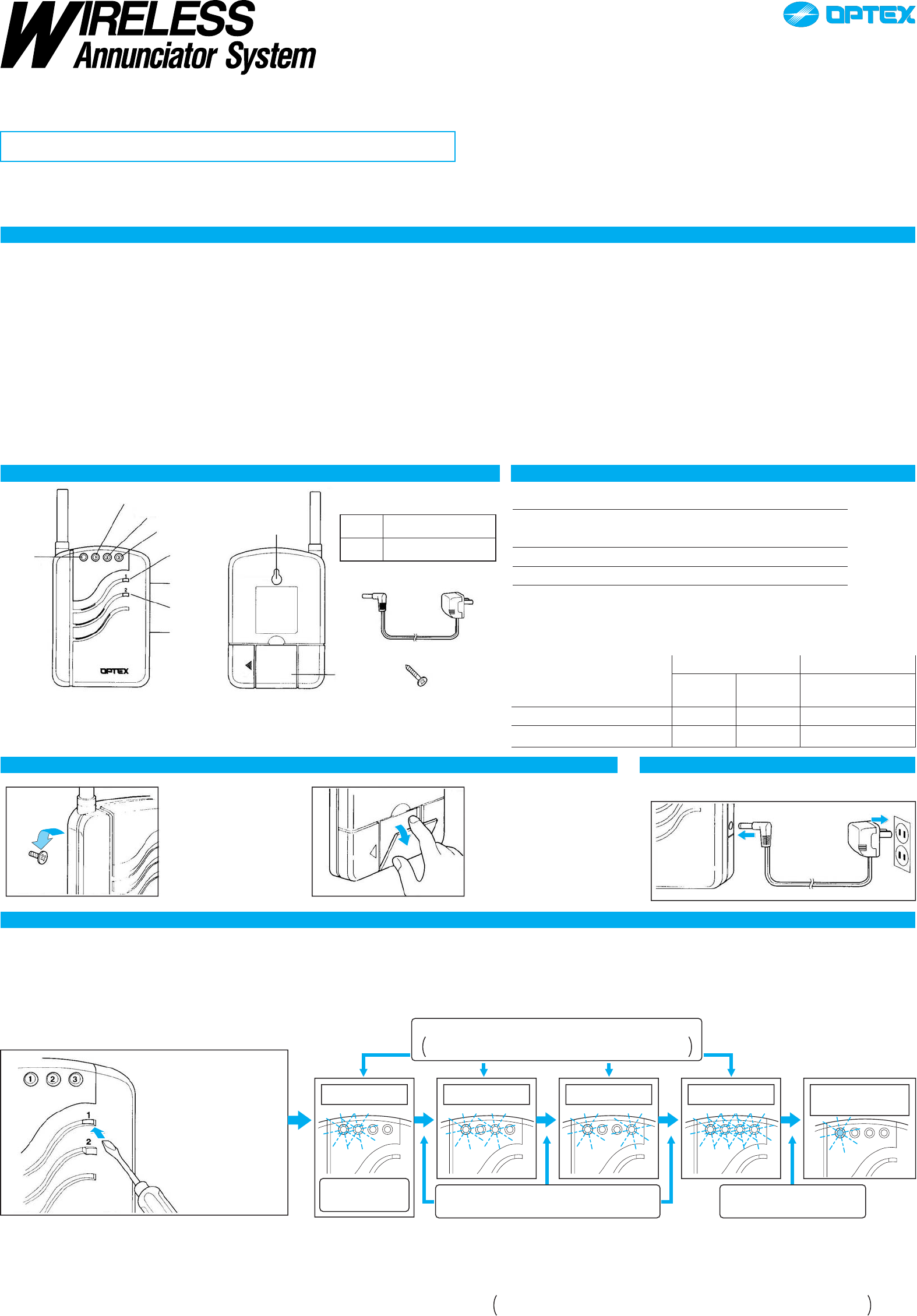
Mounting on a wall
Use the mounting screw on
a wall. Leave some length
of the screw out for the
mounting hole of the TR-
10U.
Desktop
Pull out the stand on the
back of the TR-10U and
place it on any flat surface.
PART IDENTIFICATION
FRONT
Power
indicator
Channel indicator 1
Channel indicator 2
Channel indicator 3
Switch 1
Power
switch
Switch 2
Adaptor
jack
BACK
Mounting
hole
Stand
Function
Switch 1 Activating “LEARN MODE”
and “TEACH MODE”
Switch 2 Activating making selection
AC Adaptor
Mounting screw
TEACH TRANSMITTER CODES TO THE REPEATER “LEARN MODE”
Each transmitter has a unique transmission code, which can be automatically “LEARN” by the TR-10U.
The TR-10U’s channel must be taught to respond to the appropriate transmitter.
The channel characteristics can be programmed as shown below.
Activate “LEARN MODE”
A) The TR-10U automatically
starts in “LEARN MODE”
if no transmitter code has
been programmed.
OR
B) Press and hold Switch 1
until the power indicator
starts to flash.
Teach the transmitter code to the TR-10U
Activate the transmitter you wish to teach the TR-10U.
The corresponding channel indicator flashes rapidly at intervals of
1 sec according to the N number of transmitters, N=Maximum 4.
Channel 1 Channel 2 Channel 3 Channel 4 Normal
Operation Status
TR-10U starts
in Channel 1. Press Switch 2 to advance to the next
channel. Press Switch 2 to revert to
normal operation status.
Notes:
• Revert to normal operation status before use.
• Verify that each transmitter has been learned by the TR-10U by triggering them.
• Turning off the devices, or losing power will not affect the transmitter or the TR-10U’s code memory.
Erasing Codes from the TR-10U’s Memory
1) Hold Switch 1 until the power indicator starts to flash.
2) Press Switch 2 until the appropriate channel indicator is lit.
3) Press Switch 1 to erase. Channel indicator will start to flash.
4) Press Switch 2 a few times until the power indicator stops flashing and remains lit.
Note: To erase all programming and revert to the factory default setting, turn on the
power while pressing and holding Switch 1.
MAXIMUM RECEPTION/TRANSMISSION RANGE
RECEPTION (TRANSMITTER TO TR-10U)
1000 ft. (300 m) (with TD-10U, open field, line of sight)
700 ft. (210 m) (with TS-10U/TC-10U, open field, line of sight)
TRANSMISSION (TR-10U TO RECEIVER)
1000 ft. (300 m) (with RC-10U/RG-10U, open field, line of sight)
Measurements were made over and level unobstructed ground. Natural or man-made
obstacles and other environmental factors can interfere with or otherwise reduce the
transmission range. Always confirm the actual transmission range during the system
installation. Please also use the information below as a reference for the transmission
performance.
RECEPTION from
TD-10U TS-10U
TC-10U
TRANSMISSION to
RC-10U
RG-10U
Plaster construction:
Reinforced concrete construction:
POWER CONNECTION
Use only the power adaptor supplied with the product.
150 ft. (45m)
100 ft. (30m)
110 ft. (33m)
70 ft. (21m)
150 ft. (45m)
100 ft. (30m)
* When you will waste product, please disassemble the product and waste according to states law.