P Com PMP-01-240 Point-to-Multipoint Radio User Manual Cover
P Com Inc Point-to-Multipoint Radio Cover
P Com >
Operation Manual

November 1999
No. M68333 Rev. A
Issued by P-COM, Inc.
1801 Penn Street, Melbourne, Florida 32901 Printed in U.S.A
Every effort has been made to ensure that the information contained herein is complete and accurate. However the
information contained in this manual is subject to change without notice and P-COM reserves the right to change
specifications of hardware and software without prior notice and assumes no responsibility for any damages result-
ing from any errors or omissions in this manual. P-COM’s obligations regarding the use or application of its products
shall be limited to those commitments to the purchaser set forth in its Standard Terms and Conditions of Sale for a
delivered product.
© Copyright 1999, P-COM, Inc. All rights reserved. This document contains information Confidential and Proprietary
to P-COM, Inc. No part of this publication may be reproduced or transmitted by any means and disclosure or distribu-
tion of its contents outside the company in any form without written consent from P-COM is strictly prohibited.
Tel-Link
Point-To-Multipoint
Sector Terminal Installation &
Maintenance Manual
.

November 1999
M68333 Rev. A Tel-Link PMP - Sector Terminal Installation & Maintenance Manual i
Tel-Link Point-To-Multipoint
Sector Terminal Installation & Maintenance Manual
Revision Page
Approval Signature
Rev By Desription of Changes Date
ARAD Initial Release 11/08/99
Title Signature Date
Executive Vice President for
Engineering
Program Management
Quality Assurance
Customer Service
Engineering
Technical Writer

November 1999
ii M68333 Rev. A Tel-Link PMP - Sector Terminal Installation & Maintenance Manual
This Page Intentionally Left Blank

November 1999
M68333 Rev. A Tel-Link PMP - Sector Terminal Installation & Maintenance Manual iii
Tel-Link Point-To-Multipoint
Sector Terminal Installation Manual
Contents
1.0 General Information.......................................................................................................... 1-1
1.1 Manual Organization.............................................................................................. 1-1
1.2 FCC Requirements Summary................................................................................ 1-2
1.3 Requesting Changes.............................................................................................. 1-2
1.4 Special Notations................................................................................................... 1-3
1.5 General Safety Reminders..................................................................................... 1-3
1.6 P-COM PMP Terminology...................................................................................... 1-4
2.0 Sector Terminal Overview................................................................................................ 2-1
2.1 Indoor Unit (IDU).................................................................................................... 2-2
2.2 Sector ODU Power Supply..................................................................................... 2-7
2.3 Outdoor Unit (ODU)............................................................................................... 2-8
2.4 Antenna ..................................................................................................... 2-9
2.5 IF Cable Run ..................................................................................................... 2-10
3.0 Tools and Test Equipment............................................................................................... 3-1
4.0 Site Preparation................................................................................................................. 4-1
4.1 ODU/Antenna Installation Preparation................................................................... 4-1
4.2 IDU Installation Preparation................................................................................... 4-2
4.3 Power Preparation.................................................................................................. 4-2
4.4 IFL Installation Preparation.................................................................................... 4-2
5.0 Equipment Receiving, Unpacking and Inspection......................................................... 5-1
5.1 Introduction ..................................................................................................... 5-1
5.2 Receiving and Unpacking the Equipment.............................................................. 5-1
5.3 Inspecting the Equipment....................................................................................... 5-2
6.0 Sector Terminal ODU Installation.................................................................................... 6-1
6.1 Introduction ..................................................................................................... 6-1
6.2 Tools Required ..................................................................................................... 6-1
6.3 Materials Required................................................................................................. 6-1
6.4 Sector Terminal ODU/Antenna Installation Procedure........................................... 6-1

November 1999
iv M68333 Rev. A Tel-Link PMP - Sector Terminal Installation & Maintenance Manual
7.0 Sector Terminal IDU Chassises & ODU Power Supply Chassis Rack Installation..... 7-1
7.1 Introduction ..................................................................................................... 7-1
7.2 Sector IDU Chassis Rack Installation.................................................................... 7-1
7.2.1 Tools Required............................................................................................. 7-1
7.2.2 Materials Required....................................................................................... 7-1
7.2.3 Sector IDU Chassis Rack Installation Procedure......................................... 7-1
7.3 ODU Power Supply Chassis Rack Installation....................................................... 7-3
7.3.1 Tools Required............................................................................................. 7-3
7.3.2 Materials Required....................................................................................... 7-3
7.3.3 ODU Power Supply Chassis Rack Installation Procedure........................... 7-3
8.0 Sector Terminal Wire and Cabling Installation............................................................... 8-1
8.1 Introduction ..................................................................................................... 8-1
8.2 Ground, Power and Signal Wiring.......................................................................... 8-1
8.2.1 Tools Required............................................................................................. 8-1
8.2.2 Material Required......................................................................................... 8-1
8.2.3 Grounding.................................................................................................... 8-2
8.2.4 AC Power Supply......................................................................................... 8-5
8.2.4.1 ODU Power Supply Chassis........................................................... 8-5
8.2.4.2 Sector IDU Chassises..................................................................... 8-5
8.2.5 DC Power Supply......................................................................................... 8-6
8.2.5.1 ODU Power Supply Chassis........................................................... 8-6
8.2.5.2 Sector IDU Chassises..................................................................... 8-7
8.2.6 IFL Cabling................................................................................................... 8-9
8.3 IDU to NMS and CPE Cabling................................................................................ 8-10
8.3.1 Tools Required............................................................................................. 8-10
8.3.2 Material Required......................................................................................... 8-10
8.3.3 NMS Cabling................................................................................................ 8-10
9.0 Sector Terminal IDU Board Installation.......................................................................... 9-1
9.1 Introduction ..................................................................................................... 9-1
9.2 Board Installation................................................................................................... 9-3
9.3 Power Supply Installation....................................................................................... 9-4
9.4 Board Removal ..................................................................................................... 9-4
9.5 Power Supply Removal.......................................................................................... 9-5
10.0 Sector Terminal Initial Power Application...................................................................... 10-1
10.1 DC Power Application............................................................................................ 10-1
10.2 AC Power Application............................................................................................ 10-1

November 1999
M68333 Rev. A Tel-Link PMP - Sector Terminal Installation & Maintenance Manual v
11.0 Initial Terminal Configuration and Testing..................................................................... 11-1
11.1 Terminal Configuration........................................................................................... 11-1
11.2 Antenna Alignment................................................................................................. 11-3
11.3 Terminal Commissioning........................................................................................ 11-3
11.3.1 LED Functionality....................................................................................... 11-3
11.3.2 Hot Swap/Redundancy Test...................................................................... 11-5
11.3.2.1 Sector ATM Controller (SAC)...................................................... 11-5
11.3.2.2 Modulators................................................................................... 11-6
11.3.2.3 ODU Mux..................................................................................... 11-6
11.3.2.4 FDMA Demodulators................................................................... 11-6
11.3.3 Power-up Restoration................................................................................ 11-7
11.3.4 ATM Connectivity (End-to-End) Test......................................................... 11-7
12.0 Technical Support............................................................................................................. 12-1
12.1 Warranty ..................................................................................................... 12-1
12.2 Return Process ..................................................................................................... 12-1
APPENDIX A: PMP Installation Procedure Checklist................................................................ A-1
APPENDIX B: Site Survey Checklist........................................................................................... B-1
Glossary.............................................. ..................................................................................... Gloss-1

November 1999
vi M68333 Rev. A Tel-Link PMP - Sector Terminal Installation & Maintenance Manual
This Page Intentionally Left Blank

November 1999
M68333 Rev. A Tel-Link PMP - Sector Terminal Installation & Maintenance Manual vii
List of Figures
Figure 2-1 - Example of Simplified Base Station Site...................................................................... 2-1
Figure 2-2 - Sector IDU Configuration (Block Diagram).................................................................. 2-3
Figure 2-3 - Sector IDU Chassis...................................................................................................... 2-4
Figure 2-4 - Basic IDU Chassis (Rear View)................................................................................... 2-5
Figure 2-5 - Expansion IDU Chassis (Rear View)........................................................................... 2-6
Figure 2-6 - Sector ODU Power Supply (Front View)...................................................................... 2-7
Figure 2-7 - Sector ODU Power Supply AC (Rear View)................................................................ 2-7
Figure 2-8 - Sector ODU Power Supply DC (Rear View)................................................................ 2-8
Figure 2-9 - Sector Terminal Outdoor Unit...................................................................................... 2-9
Figure 6-1 - Mounting Bracket Assembly........................................................................................ 6-2
Figure 6-2 - Antenna Mount Assembly............................................................................................ 6-3
Figure 6-3 - Tx and Rx Antenna Feedhorns.................................................................................... 6-3
Figure 6-4 - 38 GHz Antenna Feedhorn.......................................................................................... 6-4
Figure 6-5 - Aligning the Sector Antenna........................................................................................ 6-4
Figure 6-6 - Attaching ODU to Antenna Mount Assembly............................................................... 6-5
Figure 6-7 -.Attaching the Waveguides........................................................................................... 6-6
Figure 6-8 - Attaching 38 GHz ODU to Antenna Mount Assembly.................................................. 6-6
Figure 7-1 - Rack Elevation of a Sector Terminal........................................................................... 7-2
Figure 8-1 - Basic Sector Chassis AC Input (Rear View)................................................................ 8-3
Figure 8-2 - Expansion Chassis AC Input (Rear View)................................................................... 8-4
Figure 8-3 - Sector ODU Power Supply AC Input (Rear View)....................................................... 8-5
Figure 8-4 - Interconnecting of the ODU Power Supply to the Sector IDU..................................... 8-6
Figure 8-5 - Sector ODU Power Supply DC Input (Rear View)....................................................... 8-7
Figure 8-6 - Basic Sector Chassis DC Input (Rear View)................................................................ 8-8
Figure 8-7 - Basic Chassis Connection to Expansion Chassis (Rear View)................................... 8-9
Figure 9-1 - Basic IDU Chassis Board Placement.......................................................................... 9-2
Figure 9-2 - Expansion IDU Chassis Board Placement.................................................................. 9-2
Figure 9-3 - Example of Printed Circuit Board................................................................................. 9-3
Figure 9-4 - Basic Sector Chassis (Rear View)............................................................................... 9-4
Figure 11-1 - LSM Interface Port of the Sector ATM Controller Card............................................. 11-2

November 1999
viii M68333 Rev. A Tel-Link PMP - Sector Terminal Installation & Maintenance Manual
This Page Intentionally Left Blank

November 1999
M68333 Rev. A Tel-Link PMP - Sector Terminal Installation & Maintenance Manual ix
List of Tables
Table 2-1 - LMR-400 Performance Characteristics....................................................................... 2-10
Table 2-2 - IFL Signals.................................................................................................................. 2-11
Table 3-1 - Recommended Tools and Equipment (Site Survey)................................................... 3-1
Table 3-2 - Recommended Tools and Equipment (Installation/Commissioning).......................... 3-2
Table 5-1 - PMP Sector Terminal Equipment Parts List............................................................... 5-2
Table 9-1 - Basic IDU Chassis Redundancy................................................................................. 9-1
Table 9-2 - Expansion IDU Chassis Redundancy......................................................................... 9-1
Table 11-1 - Board LED Indications.............................................................................................. 11-1

November 1999
x M68333 Rev. A Tel-Link PMP - Sector Terminal Installation & Maintenance Manual
This Page Intentionally Left Blank

November 1999
M68333 Rev. A Tel-Link PMP - Sector Terminal Installation & Maintenance Manual 1-1
1.0 General Information
Before installing and operating a Tel-Link Point to Multipoint (PMP) System, P-COM recommends
installation personnel read this section in its entirety. Once accomplished, the user can proceed directly to
the section or subsection of interest.
This manual provides the installation procedures and guidelines for installing hardware associated with a
PMP System. This manual is intended for personnel who are responsible for installing and testing the PMP
system. The user should keep this manual next to the system at all times.
P-COM highly recommends the user utilize the P-COM PMP Installation Procedure Checklist located in
Appendix A to ensure the correct procedures are followed. For further assistance, contact the P-COM
Technical Assistance Center (TAC) at 1-877-674-3600.
1.1 Manual Organization
This manual is part of a set of PMP manuals that focus on specific aspects of the PMP system. The set of
manuals consist of the following:
•M68330 - Tel-Link PMP System Description Manual
•M68331 - Tel-Link PMP Local Site Manager Users Manual
•M68332 - Tel-Link PMP Network Management System Users Manual
•M68333 - Tel-Link PMP Sector Terminal Installation & Maintenance Manual
•M68334 - Tel-Link PMP Remote Terminal Installation & Maintenance Manual
The Manual is divided into 12 sections providing specific information needed to install and test the PMP
System. The sections are:
Section 1: General Information - Contains discussions on
the use of this manual, summary of the manual,
special notations, and general safety reminders
Section 2: Sector Terminal Overview - Provides a descrip-
tion of the PMP equipment.
Section 3: Tools and Test Equipment Required - Provides
lists of tools and equipment necessary to perform
the installation.
Section 4: Site Preparation - Contains information on how to
prepare the installation site.
Section 5: Equipment Unpacking and Inspection - Provides
instructions on how to unpack and inspect the
PMP Equipment
Section 6: Sector Terminal Outdoor Unit Installation - Pro-
vides instructions on how to install the Outdoor
Unit.

November 1999
1-2 M68333 Rev. A Tel-Link PMP - Sector Terminal Installation & Maintenance Manual
Section 7: Sector Terminal Indoor Unit Equipment Physical
Installation - Provides instructions on how to
install the Indoor Unit.
Section 8: Sector Terminal Wiring and Cabling Installation -
Provides instructions on how to wire and cable
the Remote Terminal.
Section 9: Sector Terminal IDU Board Installation - Provides
instructions on how to install the boards making
up the Sector IDU.
Section 10: Sector Terminal Initial Power Application - Pro-
vides instructions on how to initially apply power
to the Remote Terminal.
Section 11: Initial Terminal Configuration and Testing - Pro-
vides instructions on how to configure and test the
Remote Terminal.
Section 12: Technical Support - Provides instructions on how
to contact the Technical Assistance Center.
1.2 FCC Requirements Summary
The Base Station/Sector Terminal complies with Federal Communications Commission (FCC) Parts 2 and
101 Regulations.
•FCC ID for Base Station/Sector Terminal: L5X-PMP-01-000
Operators must be familiar with the requirements of the FCC Parts 2 and 101 Regulations prior to operating
any link using the equipment. For installations outside the United States, contact local authorities for appli-
cable regulations.
1.3 Requesting Changes
P-COM welcomes any suggestions for improving this manual. A Reader Comments Form is provided at the
end of this manual for recording comments and suggestions for improvement.

November 1999
M68333 Rev. A Tel-Link PMP - Sector Terminal Installation & Maintenance Manual 1-3
1.4 Special Notations
This manual uses four levels of special notation to alert you to important information concerning your
safety, proper equipment handling, or useful tips for easier operation. These notations are shown below in
descending order of importance
DANGER! Indicates that personal injury can result if you do not comply with the given instruction. A
DANGER! statement will describe the potential hazard, its possible consequences, and the
steps you must take to avoid personal injury.
WARNING! Indicates that serious damage to the equipment can result if you do not comply with the
given instruction. A WARNING! statement will describe the potential hazard, its possible
consequences, and the steps you must take to avoid serious equipment damage.
CAUTION! Indicates that equipment damage and/or process failure can result if there is a failure to
comply with the given instruction. A CAUTION! statement will describe the potential
hazard, its possible consequences, and the steps that must be taken to avoid equipment
damage and/or process failure.
NOTE: Provides supplementary information to emphasize a point or procedure, or gives a tip for
easier operation.
1.5 General Safety Reminders
To prevent possible personal injury or equipment damage, always observe the following rules:
•Installation and operations personnel should be familiar with the safety requirements before
attempting installation or operation of the equipment covered by this manual. Failure to follow
the requirements could result in death or injury to personnel and/or damage to the equipment.
•Always examine the general area for any potential hazards (such as wet floors or overhead
wires) before beginning installation.
•Observe all DANGER! notations. Dangerously high voltages are present within this equipment
when in operation. Lethal line voltages may be present unless the power has been discon-
nected.
•Always remove any jewelry or other personal items that may conduct electricity before begin-
ning installation.
•Keep away from live circuits. Whenever feasible in verifying circuits, check by continuity and
resistance methods with all power off, rather than directly checking voltages.
•Observe grounding precautions. Verify the unit under test or being installed and all measure-
ment equipment are properly grounded.

November 1999
1-4 M68333 Rev. A Tel-Link PMP - Sector Terminal Installation & Maintenance Manual
•Do not test alone. Testing or adjusting the equipment should only be carried out in the pres-
ence of a person qualified to render aid.
•Use proper lifting techniques when lifting the equipment to prevent injury.
•It is the responsibility of the installer and the user to ensure that the public is not exposed to
excessive RF levels. Such information must be posted near the antenna in the form of caution
or warning notes and signs.
1.6 P-COM PMP Terminology
For the ease of the reader, a Glossary is provided at the end of the manual defining terminology used in
P-COM Tel-Link PMP Manuals.
November 1999
M68333 Rev. A Tel-Link PMP - Sector Terminal Installation & Maintenance Manual 2-1
2.0 Sector Terminal Overview
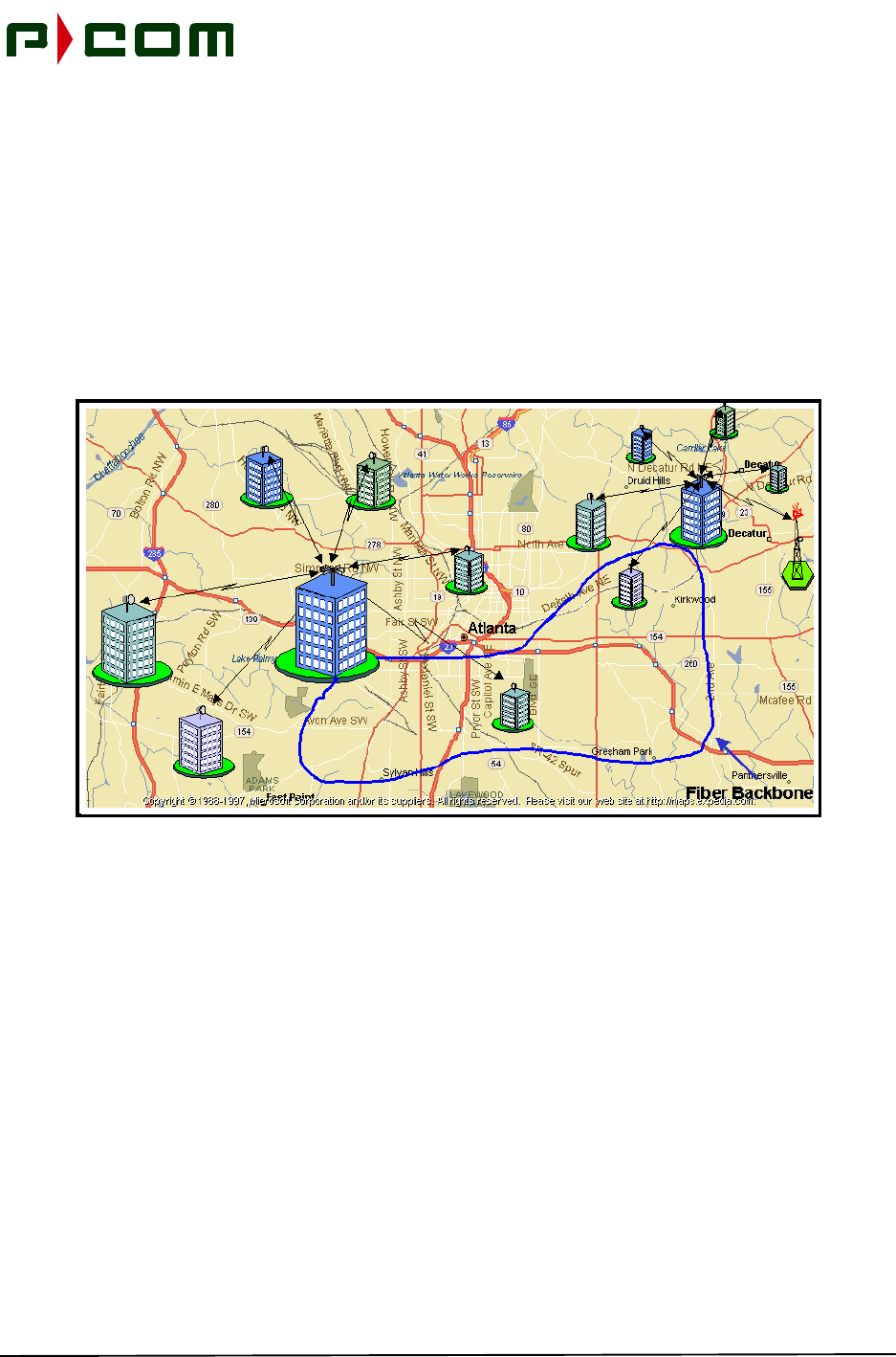
The PMP network is composed of one or more base stations that are strategically located within the desired
coverage area (refer to Figure 2-1). Base Station/Sector Terminals are located at the center of each cell
and have a radius of up to 10 Km depending on the RF frequency, climate type, desired network availabil-
ity, line-of-sight profiles, and traffic capacity requirements. The Base Station consists of 1 to 24 Sectors. A
sectorized area of a Base Station/Sector Terminal is supported by 1 to 5 Sector Indoor Units (IDUs),
depending on the number of Remote Terminals located in that sector. Each Sector communicates directly
with the Remote Terminal within a sector area of 22.5° to 90° of coverage within the 360° area around the
base station. Each base station also interfaces to the Public Switched Network (PSN) through a high-speed
backbone link.
Figure 2-1 - Example of Simplified Base Station Site
The system utilizes an ATM cell-multiplexed, continuous carrier to transmit data from the base station to the
Remote Terminals. Each sector uses one or more downlink carriers to deliver these cells to the Remote
Terminals. These carriers are transmitted at different frequencies to avoid interference. Either a FDMA or
TDMA scheme is used by the Remote Terminals to transmit information to the Base Station. When FDMA
uplinks are used from the Remote Terminals, each Terminal communicates on a separate frequency chan-
nel with a demodulator at the Base Station for each channel. When TDMA uplinks are used from the
Remote Terminals, multiple remotes share a single carrier by transmitting in designated time slots.

November 1999
2-2 M68333 Rev. A Tel-Link PMP - Sector Terminal Installation & Maintenance Manual
The Sector Terminal consists of following components:
•Basic IDU chassis containing Modulators, FDMA Demodulators, Burst TDMA Demodulators,
OC-3 SAC and ODU Multiplexers (MUX)
•Optional Expansion IDU Chassis containing a Sector Expansion Controller (SEC), TMDA or
FDMA Demodulator and Receive IF Demux's
•Sector ODU Power Supply consisting of a rack mounted unit supplying power to the ODU
•Outdoor Unit(s) ODUs containing the RF components
•Antenna and mounting hardware
•Interfacility Link (IFL) consisting of one coaxial cable connecting the ODU to the Indoor Unit
(IDU)
2.1 Indoor Unit (IDU)
The Sector IDU is located indoors at the Base Station site and is connected to the Sector ODU via an IFL
cable. The Sector Basic IDU is comprised of the following components:
•Basic rack mount chassis with IDU power supplies
•Modulators
•Demodulators (FDMA network)
•Burst Demodulators (TDMA network)
•Sector ATM Controllers
•ODU MUXs
The Sector Expansion IDU is comprised of the following components:
•Expansion rack mount chassis with IDU power supplies
•Demodulators (FDMA)
•Demodulators (TDMA)
•Sector Expansion Controllers
•Receive IF Demultiplexers
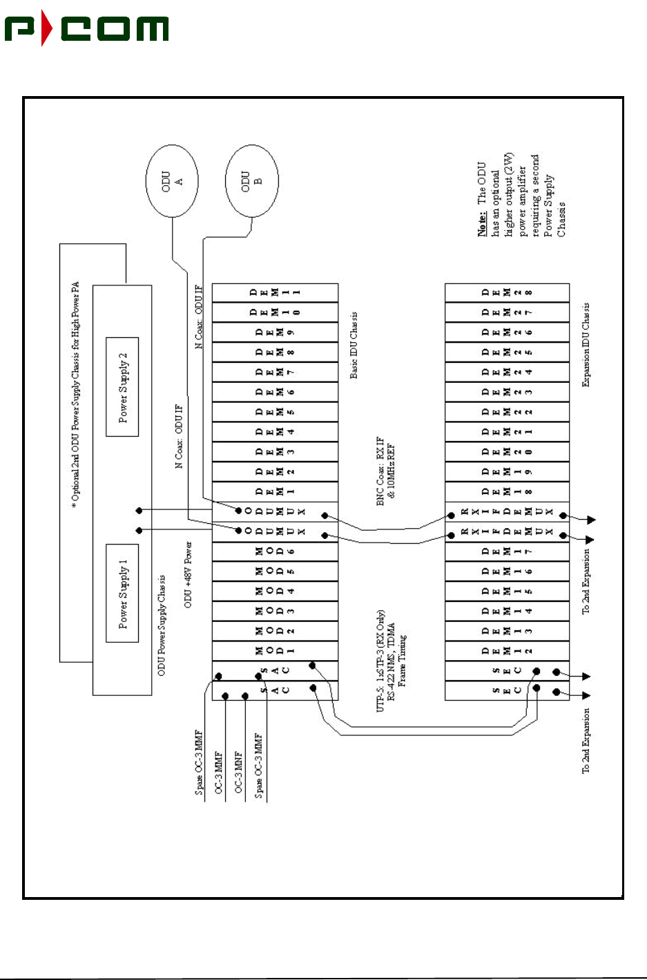
Chassis configuration is performed from a Local Site Manager (LSM) laptop or desktop PC using P-COM’s
WaveView Windows application. Each card has specific variables and must be properly configured in order
to establish RF and data links. Each card in the chassis has a specific slot where it is to be located. Figure
2-2 is a block diagram illustrating a Basic ID Chassis and an Expansion IDU Chassis configuration.
November 1999
M68333 Rev. A Tel-Link PMP - Sector Terminal Installation & Maintenance Manual 2-3
Figure 2-2 - Sector IDU Configuration (Block Diagram)
November 1999
2-4 M68333 Rev. A Tel-Link PMP - Sector Terminal Installation & Maintenance Manual
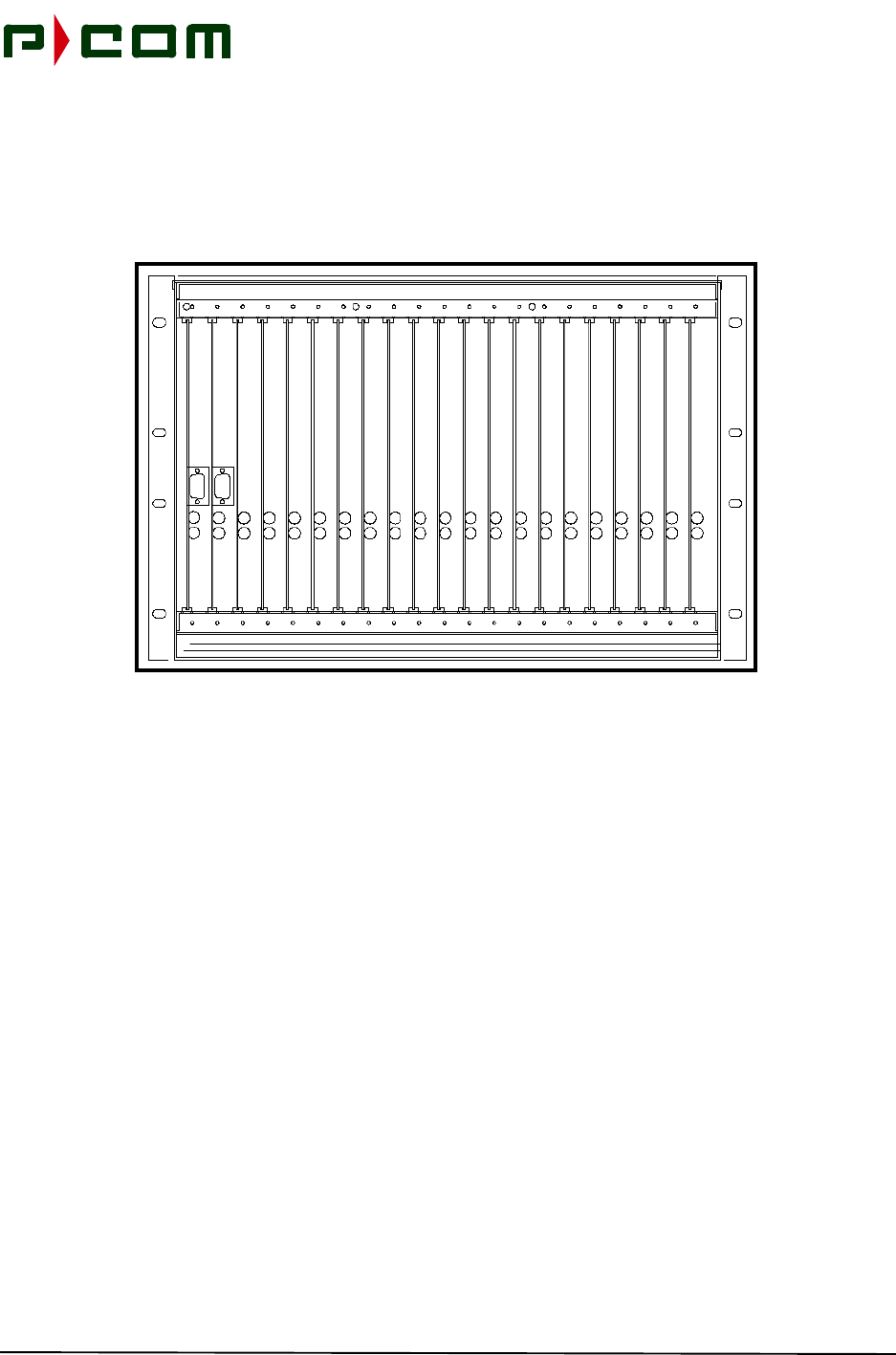
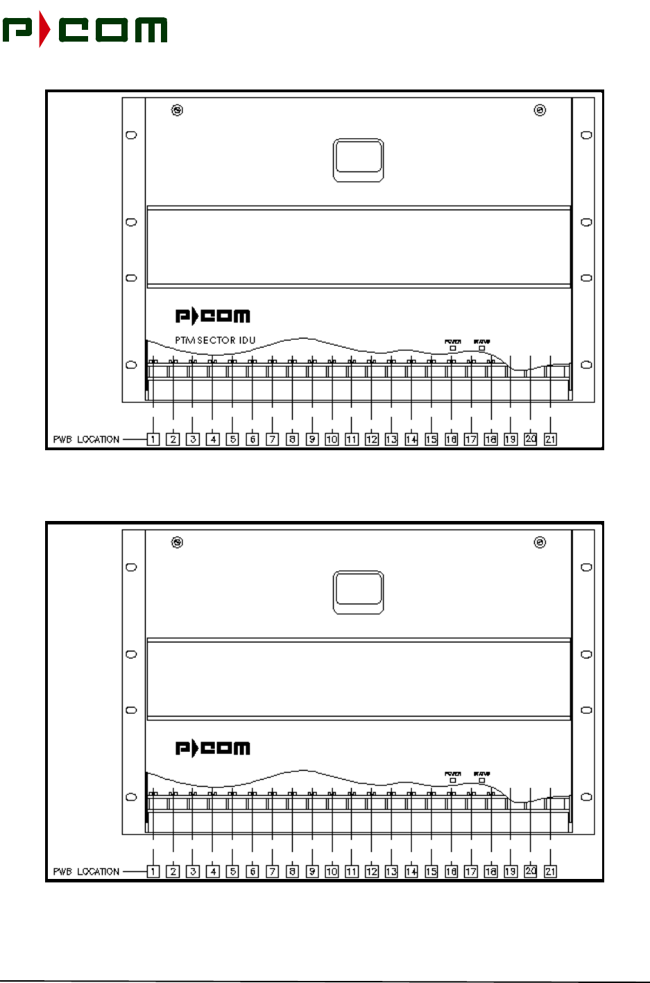
Both IDU chassis measure 38 cm (H) x 45 cm (W) x 43 cm (D) (15" x 17.75" x 17") and are rack mounted.
Figure 2-3 illustrates a Sector IDU Chassis. Figure 2-4 and Figure 2-5 show the rear views of the Basic IDU
Chassis and Expansion IDU Chassis. The sector IDU chassis can be connected to an optional battery
Uninterruptible Power Supply (UPS) system that can provide hours of operation during primary power fail-
ure.
Figure 2-3 - Sector IDU Chassis
November 1999
M68333 Rev. A Tel-Link PMP - Sector Terminal Installation & Maintenance Manual 2-5
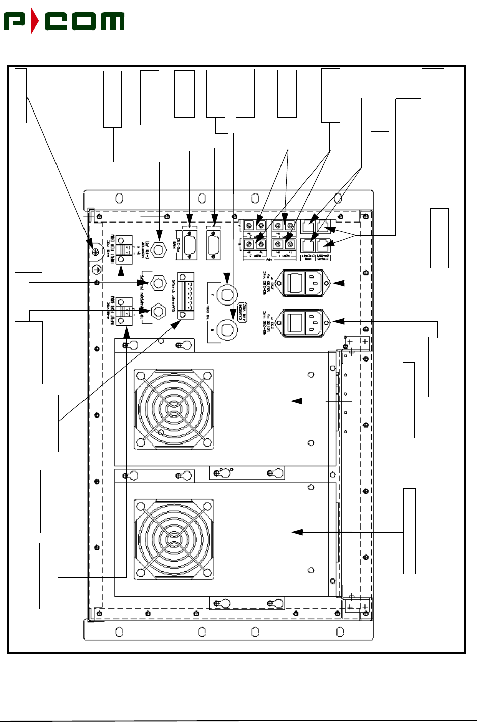
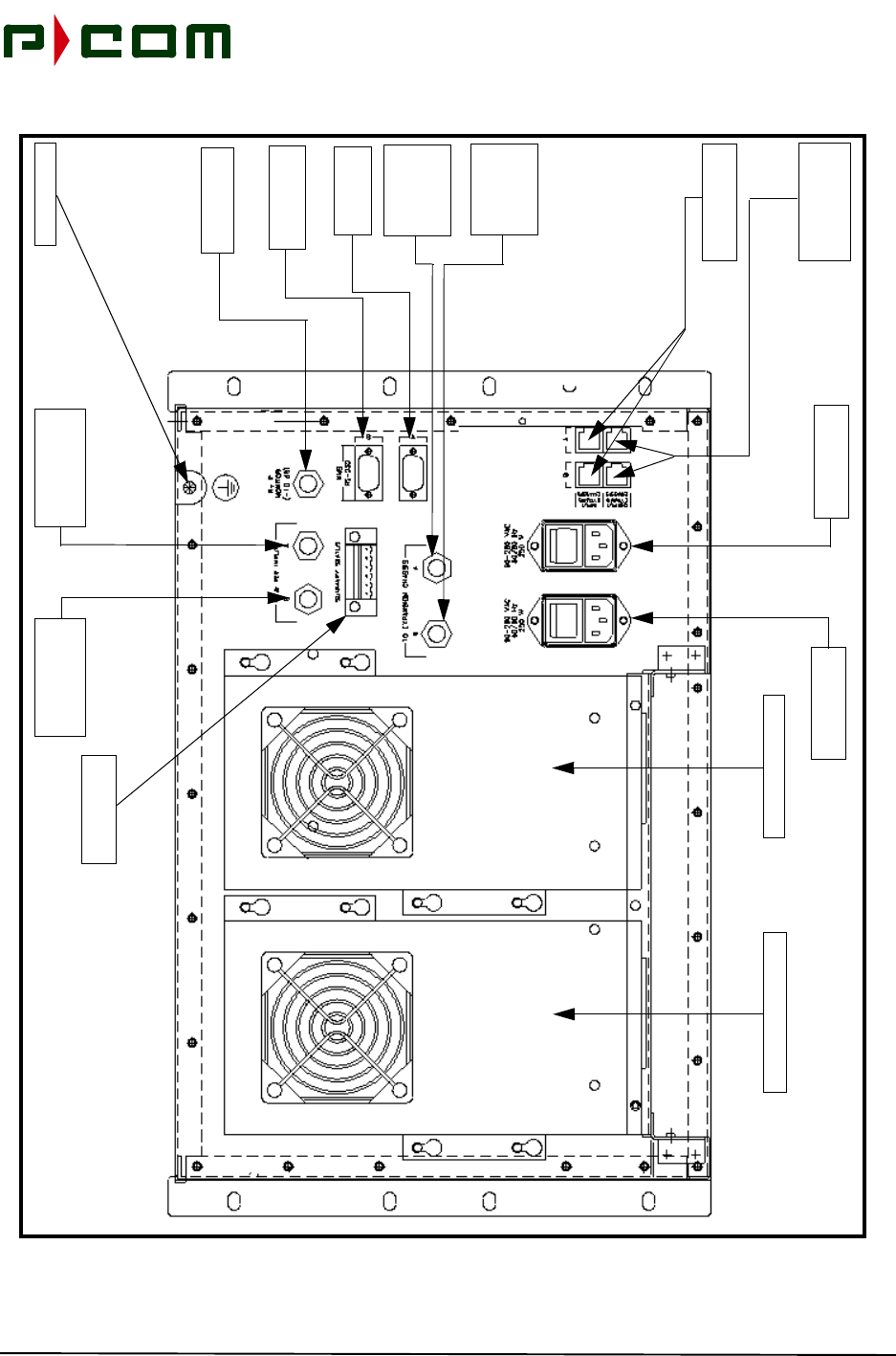
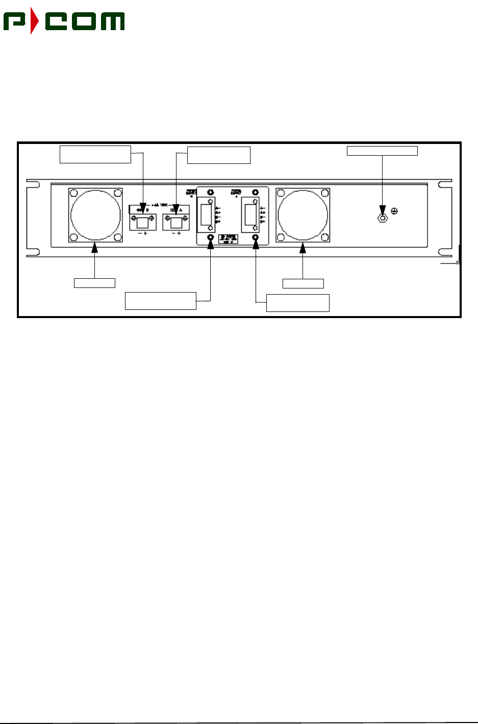
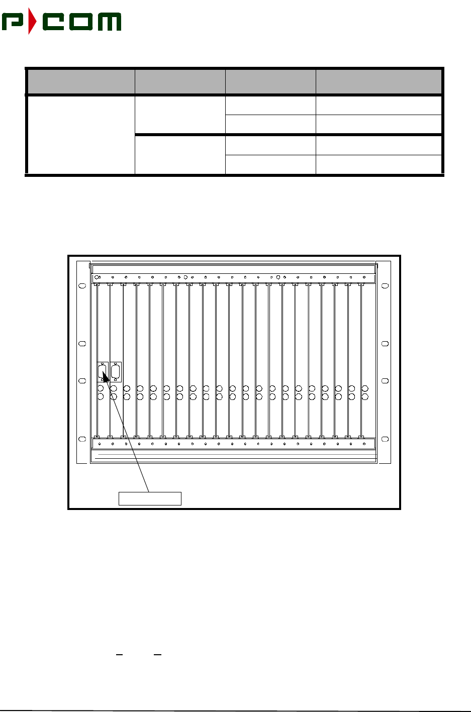
Figure 2-4 - Basic IDU Chassis (Rear View)
Secondary ODU DC
Power Supply Port
Primary Power Supply
Secondary Power Supply
Primary AC Input
Power Port
Secondary AC
Input Power Port
Chassis Ground
Primary ODU DC
Power Supply Port
Monitor Interface
ATM Ethernet
Interface Ports
Primary IFL
Interface Port
Secondary IFL
Interface Port
Primary NMS
Interface Port
Secondary NMS
Interface Port
Primary
Expansion Chassis
Interface Port
Secondary
Expansion Chassis
Interface Port
Port
Primary ATM
Interface Ports
Secondary ATM
Interface Ports
Summary Alarms
Interface Ports
Expansion Chassis
Interface Ports

November 1999
2-6 M68333 Rev. A Tel-Link PMP - Sector Terminal Installation & Maintenance Manual
Figure 2-5 - Expansion IDU Chassis (Rear View)
Primary Power Supply
Secondary Power Supply
Primary AC Input
Power Port
Secondary AC
Input Power Port
Chassis Ground
Monitor Interface
ATM Ethernet
Interface Ports
Secondary
Interface Port
Primary NMS
Interface Port
Secondary NMS
Interface Port
Primary
Sector Chassis
Interface Port
Secondary
Sector Chassis
Interface Port
Port
Summary Alarms
Interface Ports
Expansion Chassis
Interface Ports
Chassis
Interface Port
Primary
Interface Port
Chassis
Interface Port
November 1999
M68333 Rev. A Tel-Link PMP - Sector Terminal Installation & Maintenance Manual 2-7
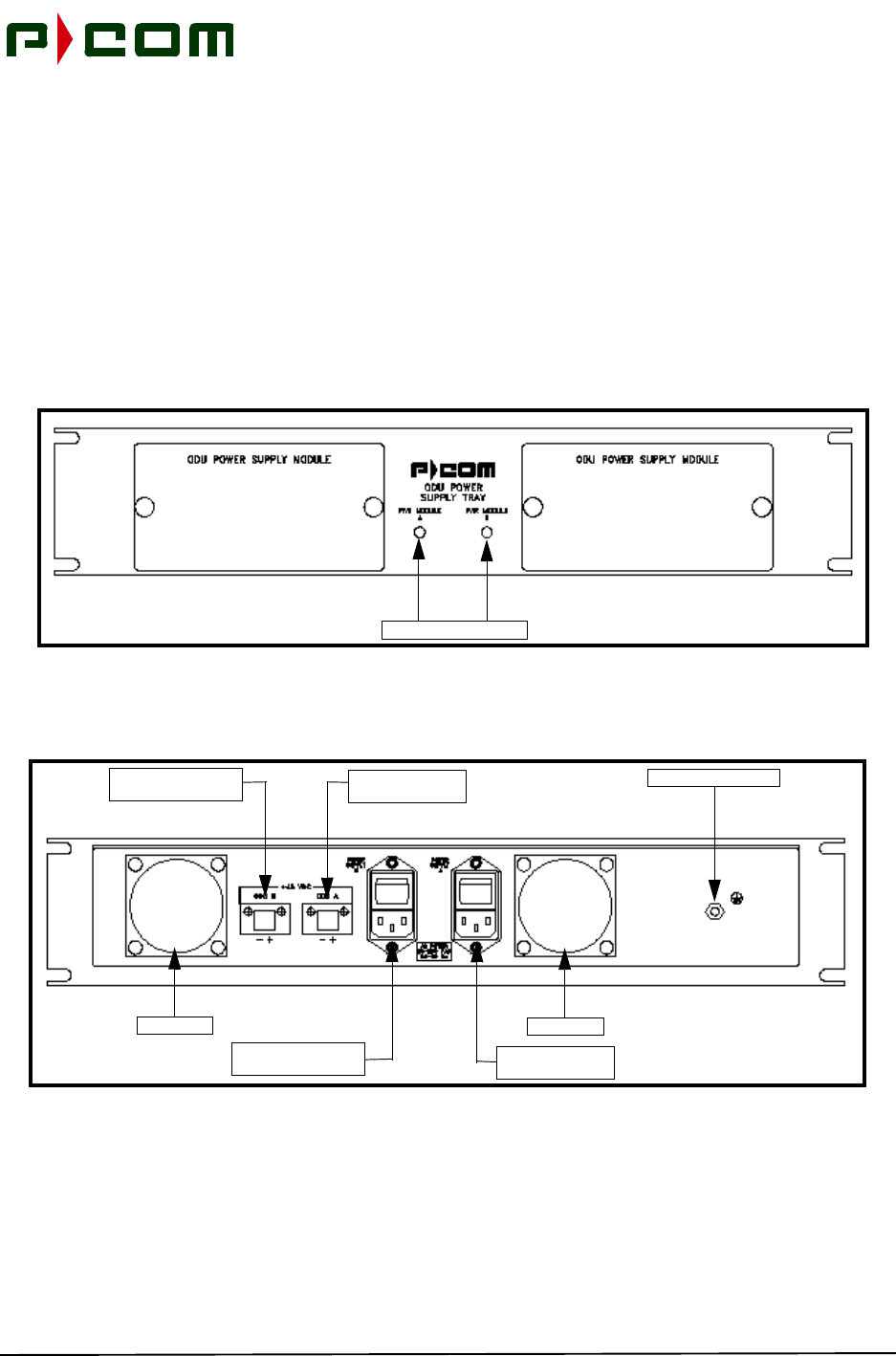
2.2 Sector ODU Power Supply
The Sector ODU Power Supply is a rack mounted unit supplying DC power to the ODUs and designed to
avoid single points of failure and ease of replacement of failed components. This unit is redundant utilizing
two power supplies within the chassis that load share and is fan cooled (refer to Figure 2-6, Figure 2-7 and
Figure 2-8). A single Power Supply Unit is capable of powering two standard Sector ODU’s, thus allowing
replacement of an ODU Power Supply Module without causing service interruption. The two Power Supply
Modules are load sharing. When Power Supply Module B is removed, +48 VDC will still be present on the
output connector labeled ODU B. When the optional higher power (2W) output ODU is selected, a second
ODU Power Supply is required.
Figure 2-6 - Sector ODU Power Supply (Front View)
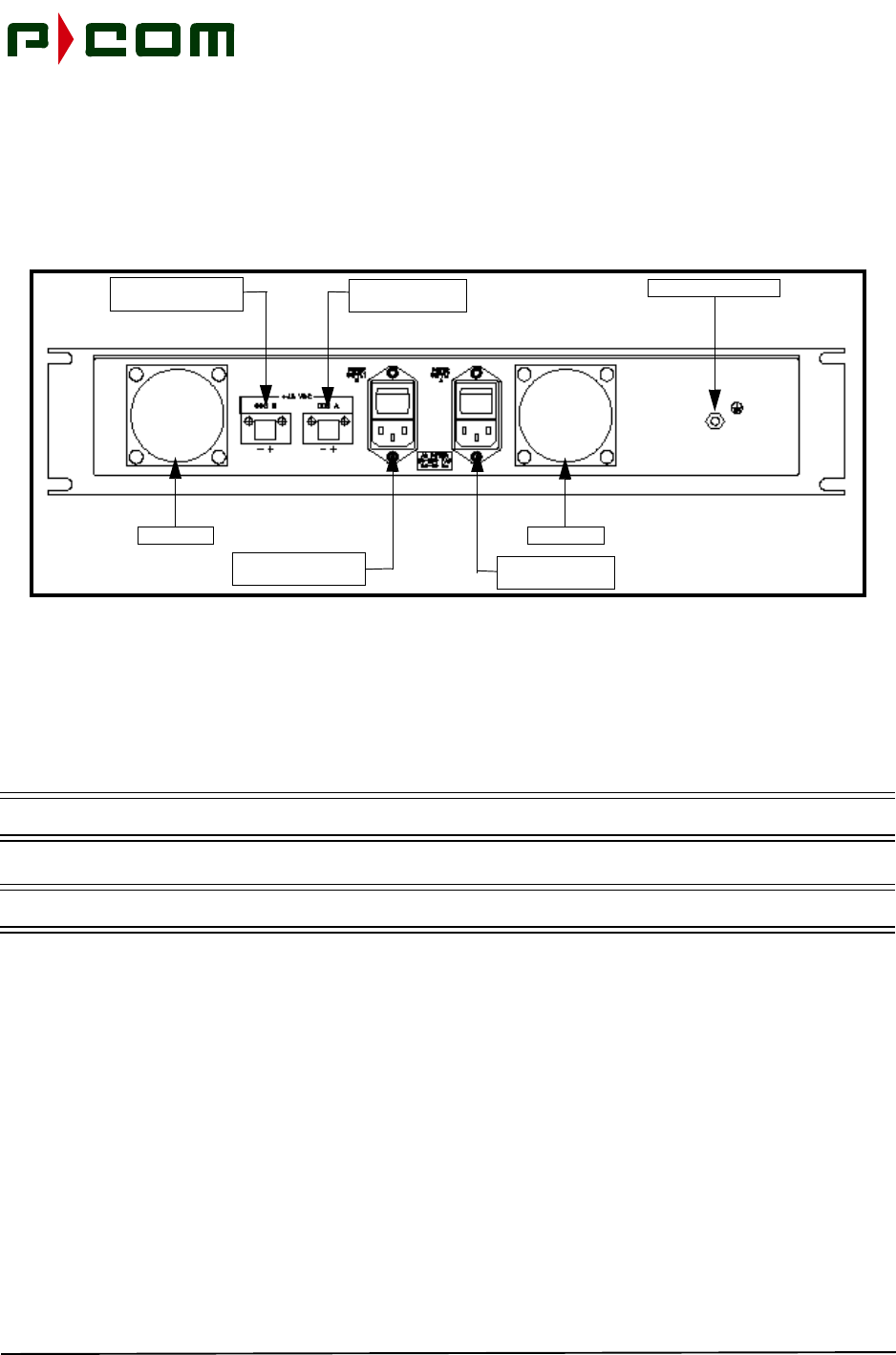
Figure 2-7 - Sector ODU Power Supply AC (Rear View)
Active LED Indicators
Chassis Ground Stud
Cooling Fan
Primary AC Power
Supply Input Port
Secondary AC Power
Supply Input Port
Secondary DC Power
Supply Output Port Primary DC Power
Supply Output Port
Cooling Fan

November 1999
2-8 M68333 Rev. A Tel-Link PMP - Sector Terminal Installation & Maintenance Manual
Figure 2-8 - Sector ODU Power Supply DC (Rear View)
2.3 Outdoor Unit (ODU)
Figure 2-9 illustrates a typical RF/Antenna configuration for the Sector Terminal Outdoor Unit. The packag-
ing includes the following components:
•ODU Enclosure
•RF Electronics
•ODU Controller Card responsible for controlling and monitoring ODU functions and for interfac-
ing with the IDU
The ODU is frequency agile so that the same ODU can typically be used throughout the entire allocated fre-
quency band. Subsequently, this reduces sparing levels.
The ODU meets all National Electrical Code requirements pertaining to lightning and power transients and
meets or exceeds FCC and ETSI regulations pertaining to conducted and radiated Electromagnetic Emis-
sions.
The ODU is sealed against the environment and is capable of functioning in ambient temperatures ranging
from -40°C to +60°C, with up to 100% relative humidity. The ODU can survive steady state winds of 40 m/s
with gusts to 55 m/s (89 mph/123 mph).
Chassis Ground Stud
Cooling Fan
Primary DC Power
Supply Input Port
Secondary DC Power
Supply Input Port
Secondary DC Power
Supply Output Port Primary DC Power
Supply Output Port
Cooling Fan

November 1999
M68333 Rev. A Tel-Link PMP - Sector Terminal Installation & Maintenance Manual 2-9
Figure 2-9 - Sector Terminal Outdoor Unit
2.4 Antenna
The Sector Antenna is a lensed-horn antenna. For 24-26 GHz; two horns are used for transmit and receive
functions. At 38 GHz, a single horn antenna is used. Antennas are selected based on desired horizontal or
vertical polarizations and for azimuth beamwidths of 22.5°, 30°, 45°, 60° and 90°. The elevation beamwidth
is typically 6°.
The antennae are mounted on a rectangular mounting plate with mounting hinges used to install on a pole.
One of the hinges allows for elevation adjustment. Components of the antenna are:
•Waveguide
•Radome/Horn
•Mount
November 1999
2-10 M68333 Rev. A Tel-Link PMP - Sector Terminal Installation & Maintenance Manual
2.5 IF Cable Run
A single coaxial cable is used to connect the sector ODU to the Basic IDU chassis. This carries the transmit
IF signal, receive IF signal, telemetry, 10 MHz Reference Signal and DC Power between the IDU Chassis
and Sector ODU. The IDU chassis and ODU contain “N” type female connectors for interconnection of the
coaxial cable. The DC power for the ODU is supplied to the Basic IDU chassis from the rack mounted ODU
Power Supply chassis.
Double-screened LMR-400 coaxial cable is recommended for its good EMC performance and possess the
following characteristics described in Table 2-1:
Table 2-1 - LMR-400 Performance Characteristics
Property LMR-400
Shielding > 90 dB
Impedance 50 Ohms
Velocity 85%
Capacitance 2.39 pF/ft
Center Conductor 0.109” (0.28 cm)
Attenuation (25°)30 MHz 0.70 dB/100 ft
220 MHz 1.80 dB/100 ft
450 MHz 2.7 dB/100 ft
900 MHz 3.90 dB/100 ft
Phase Stability +/- 10 ppm/deg C
DC Resistance 1.39 Ohms/1000 ft
Bend Radius 1” (2.54 cm)
Temperature Range -40°F to 185°F (-40°C to 85°C)
Maximum Length 1000 Feet (300 meters)
IF Connector Type N Male
November 1999
M68333 Rev. A Tel-Link PMP - Sector Terminal Installation & Maintenance Manual 2-11
Table 2-2 shows the signals carried between the Sector IDU and Sector ODU on the coaxial IFL cable:
Table 2-2 - IFL Signals
IFL Signal Frequency Variation
IDU Transmit 205 MHz ±5 MHz
IDU Receive 490 MHz ±5 MHz
Telemetry 800 KHz
(On/Off Keying) 30 KHz
Reference Signal 10 MHz 1 ppm
IFL Power Voltage Variation
ODU Power +44 VDC +40 to +57 VDC
IFL Connector Termination 1 Termination 2
Type N Male IDU ODU

November 1999
2-12 M68333 Rev. A Tel-Link PMP - Sector Terminal Installation & Maintenance Manual
This Page Intentionally Left Blank

November 1999
M68333 Rev. A Tel-Link PMP - Sector Terminal Installation & Maintenance Manual 3-1
3.0 Tools and Test Equipment
Table 3-1 and Table 3-2 are the recommended list of tools and test equipment necessary for the following
activities:
•Site Survey
•Installation
•Commissioning
NOTE: This is a typical Installers tool kit. On some installations additional tools may be necessary.
Table 3-1 - Recommended Tools and Equipment (Site Survey)
DESCRIPTION QNTY BRAND PART NO.
Area Map 1NA NA
Binoculars 1NA NA
Camera (Digital Preferred) 1NA NA
Compass 1NA NA
Computer, Laptop (Pentium) (with Link
Budget Software) 1NA NA
Flag or Red Towel (to identify site from a
distance 2NA NA
Flashlight 1NA NA
Global Positioning System Receiver 1NA NA
Multimeter, Handheld 1Klein 44100
Radio, 2-Way or Cell Phone 2NA NA
Safety Belt 2NA NA
System Configuration Document 1NA NA
Site Survey Checklist 1NA NA
Wood Stick 1Desco 517F

November 1999
3-2 M68333 Rev. A Tel-Link PMP - Sector Terminal Installation & Maintenance Manual
.
Table 3-2 - Recommended Tools and Equipment (Installation/Commissioning)
DESCRIPTION QNTY BRAND PART NO.
AC Circuit Tester 1Ideal 6-035
Antenna Alignment Tool 1P-COM 28055-1
Anti-Statitc Material Kit 1Charleswater 16430
Binoculars 1NA NA
Bit Error Rate Test Set, (with correct UIM
interface module) 1FireBerd Portable 6000A
Cable Cutter 1Klein 63050
Compass 1NA NA
Computer, Laptop (Pentium) (with Link
Budget Software) 1NA NA
Crimp Tool, Die Set (RG-58, 59) 1IDEAL 30-581
Crimp Tool Die Set, (LMR-400, RG-8) 1RF Industries RFA-4005-02
Crimp Tool 1RF Industries RFA-4005-020
Crimp Tool, (RJ-45) 1IDEAL 30-559
Crimp Tool, (Solderless Connectors) 1NA NA
Diagonal Cutters, Flush Cut 1NA NA
Flashlight 1NA NA
Global Positioning System Receiver 1NA NA
Inclinometer 1NA NA
Knife, Utility 1NA NA
Multimeter, Handheld 1Klein 44100
Pliers, Needle Nose 4” Insulated 1NA NA
Pliers, Slip Joint 6” Insulated 1NA NA
Rachet, 3/8” Drive 1NA NA
Radio, 2-Way or Cell Phone 2NA NA
RF Connector (Type N Male) AR RF Industries RFN-1006-31
Rope, Nylon 100 Ft 2NA NA
Safety Belt 2NA NA
Safety Glasses 2NA NA
Screwdriver, #1 Phillips 1NA NA
Screwdriver, #2 Phillips 1NA NA
Screwdriver, #2 Phillips Stubby 1NA NA

November 1999
M68333 Rev. A Tel-Link PMP - Sector Terminal Installation & Maintenance Manual 3-3
Screwdriver, 1/4 x 1” Slotted 1NA NA
Screwdriver, 1/4 x 4” Slotted 1NA NA
Screwdriver, 1/8 x 2” Slotted 1NA NA
Screwdriver, 1/8 x 8” Slotted 1NA NA
Screwdriver, 3/16 x 3” Slotted 1NA NA
Socket Set (Deep well) 3/8-3/4 (3/8 drive) 1NA NA
Solder 1Weller SP23
Soldering Iron, 25 watt 1NA NA
Tape Measure (25 ft) 1NA NA
Tie Wraps, Black AR NA NA
Weather Proof Tape AR NA NA
Wire Brush 1NA NA
Wire Stripper, 10-18 AWG 1IDEAL 45-120
Wire Wrap Tool, 24 & 26 Gauge, Manual 1NA NA
Wire Wrap Tool, 24 & 26 Gauge, Power 1NA NA
Wood Stick 1Desco 517F
Wrench, 8” Adjustable 1NA NA
Wrench, Combination ASE 1/4 - 3/4 Set 1NA NA
Table 3-2 - Recommended Tools and Equipment (Installation/Commissioning)
DESCRIPTION QNTY BRAND PART NO.

November 1999
3-4 M68333 Rev. A Tel-Link PMP - Sector Terminal Installation & Maintenance Manual
This Page Intentionally Left Blank

November 1999
M68333 Rev. A Tel-Link PMP - Sector Terminal Installation & Maintenance Manual 4-1
4.0 Site Preparation
Prior to beginning physical installation of the Tel-Link PMP equipment, the Site preparation work should be
complete. Site preparation includes but is not limited to the following:
•Completed Site Survey Checklist (P-COM highly recommends the use and completion of the
Site Survey Checklist located in Appendix B)
•System Configuration Document Specification
The criteria below should be evaluated prior to designating Remote to Sector terminal RF paths with the
use of Site Surveys and Link Budgets:
•An unobstructed line-of-sight
•Be within range (distance separation) with respect to the desired operational parameters (i.e.,
rain, region, availablity, modulation type, bit error rate performance, etc.)
•Be within the antenna beamwidth
NOTE: P-COM highly recommends a blower or fan be used with an enclosed rack containing three
or more IDUs.
The IDU is designed to be installed in a 19-inch equipment rack or enclosed cabinet in a location that is:
•Dry, clean and well ventilated
•Easily accessible
•Within 600 feet (with CAT-5 cable) of subsequent Customer Premise Equipment (CPE)
•Within 1000 feet of the ODU when using LMR-400 or equivalent Coaxial cable
•Compliant with all environmental specifications
4.1 ODU/Antenna Installation Preparation
Verify the location selected has the following characteristics:
•Space on pole is adequate for mounting the antenna and ODU.
•Verify the pole for the ODU/Antenna assembly is installed in the location identified on the Site
Survey Checklist.
•Verify the pole has been securely installed and is grounded per local code.

November 1999
4-2 M68333 Rev. A Tel-Link PMP - Sector Terminal Installation & Maintenance Manual
4.2 IDU Installation Preparation
Verify the location selected has the following characteristics:
•Identify IDU mounting location as specified in a completed Site Survey Checklist.
•Verify the required rack (if used) is installed, secured to the floor, and ready to accept the IDU.
•Sufficient space is provided for the installation of the ODU Power Supply.
4.3 Power Preparation
Verify the location selected has the following characteristics:
•Verify the correct power source has been provided within close proximity to the IDU location.
•Verify the power source is controlled through an appropriately sized circuit breaker or fuse
4.4 IFL Installation Preparation
NOTE: Maximum cable length of 1000 ft (300 meters) between the IDU and ODU.
P-COM recommends the IFL should be Times-Microwave LMR-400 coaxial cable.
•Verify the IFL between the ODU and Basic IDU chassis location is present.
•Verify a sufficient length of IFL is present at both ends to provide a service loop prior to being
terminated to the equipment.
•Terminate each end of the IFL with a Type-N male connector per manufacturers instructions.
•Apply liquid electrical sealant to the outdoor connector outer crimp ring to ensure a waterproof
seal between the cable and connector.

November 1999
M68333 Rev. A Tel-Link PMP - Sector Terminal Installation & Maintenance Manual 5-1
5.0 Equipment Receiving, Unpacking and Inspection
5.1 Introduction
This procedure provides information for unpacking and inspecting the PMP equipment prior to physical
installation.
5.2 Receiving and Unpacking the Equipment
At a minimum, check for the following:
STEP 1. Check the outside of the shipping crates for visible signs of damage. Crushed corners
or tears in cardboard may indicate rough handling which may result in hidden damage
to the equipment.
STEP 2. Inventory shipping crates and other packages received in the shipment. Verify that all
items listed on the Electronic Goods Descriptive Inventory or applicable shipping docu-
ment were received. Identify all missing items on the inventory sheet.
STEP 3. Record any noted damage to the outside of the packaging material on the carrier's Bill
of Lading and have the transportation company initial the sheet. All notations should
indicate location and condition.
Example: 1" x 2" scratch on left front (LF) metal panel; not LF panel
scratched. Another example would be 4" x 6" dent in center panel
(not dent in panel).
WARNING! The warranty will be violated if you do not take anti-static precautions when unpacking or
assembling the PMP boards in the PMP shelf. Circuit modules can be damaged by
electrostatic discharge. Ensure that an approved anti-static wrist strap is connected
between the wrist of the person and an electrical ground before handling any of the circuit
modules.
STEP 4. Carefully open the equipment packaging.

November 1999
5-2 M68333 Rev. A Tel-Link PMP - Sector Terminal Installation & Maintenance Manual
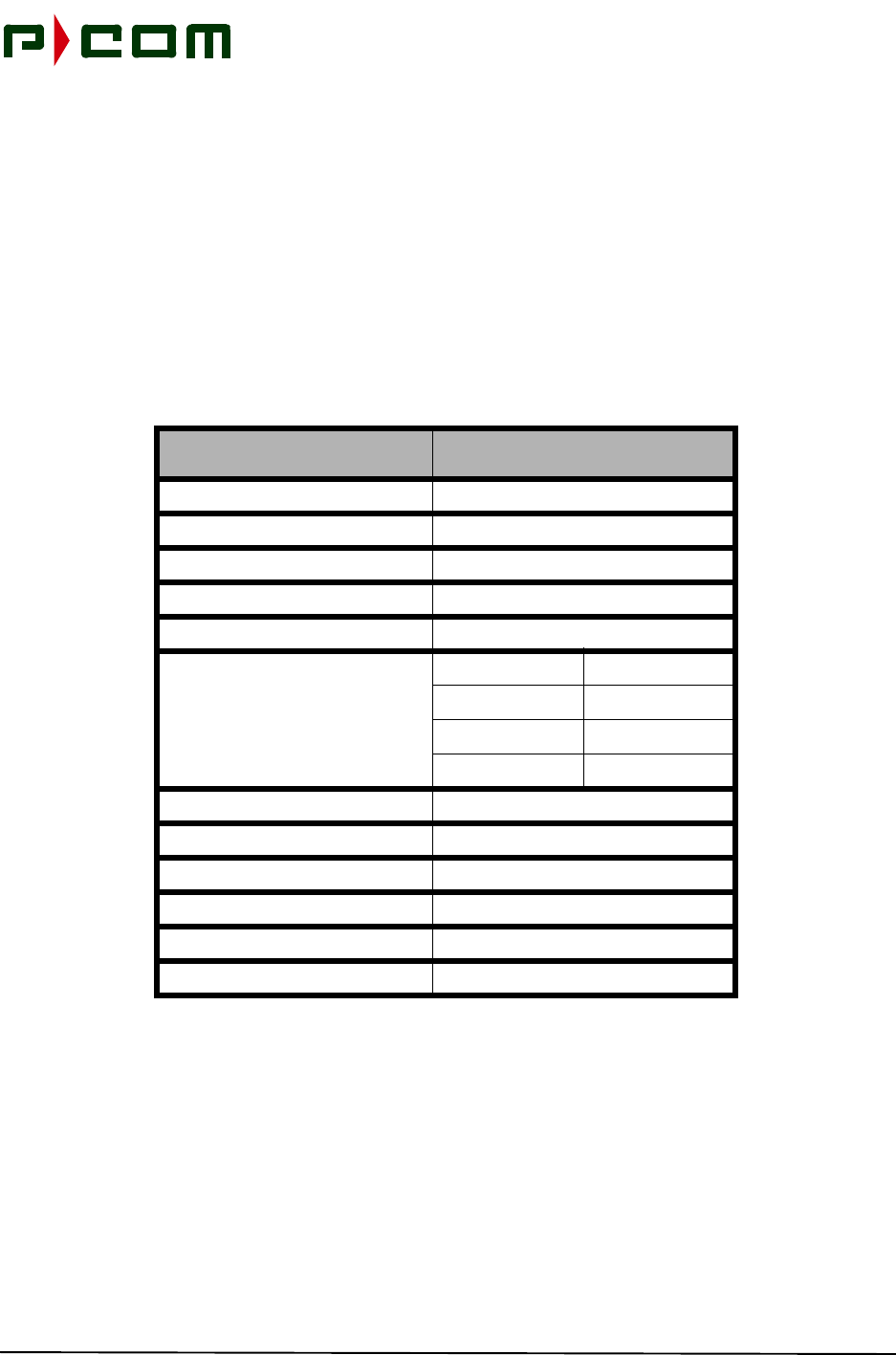
5.3 Inspecting the Equipment
STEP 1. For each of the PMP subsystems received, verify the equipment received matches the
shipping list by Part Number and Serial Number. Report any discrepancies immedi-
ately using the field return procedure outlined in Section 12 of this manual. The Tel-
Link PMP system may be ordered in different configurations. Table 5-1shows the Part
Number for all system parts. In addition, the quantities of boards for redundant and
non-redundant configurations are identified. The Equipment Parts List may contain
more than the users specific requirements.
CAUTION! Tampering with seals will void the warranty.
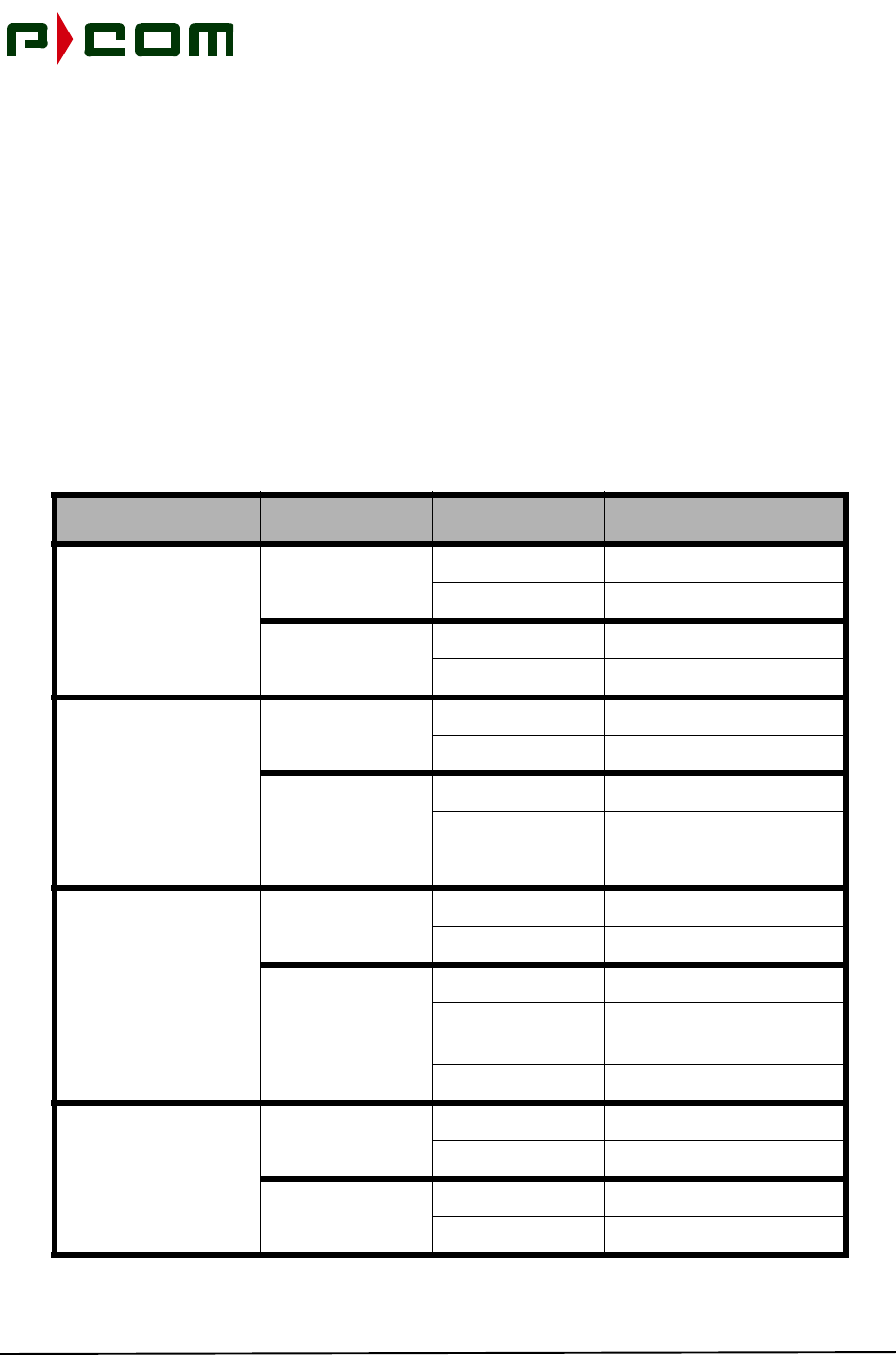
Table 5-1 - PMP Sector Terminal Equipment Parts List
SECTOR INDOOR EQUIPMENT
Description Part Number Quantity
Sector IDU Chassis 1
Sector Expansion Chassis As Required
Sector ATM Controller As Required
Modulator As Required
Demodulator As Required
ODU Multiplexer As Required
Power Supplies
ODU Power Supply 1:2
IDU 90-260 VAC Module 1:2
IDU +39 to 59VDC Module 1:2
SECTOR OUTDOOR UNIT (ODU)
Description Part Number Quantity
Sector ODU Frequency Dependent 1
Waveguide Antenna (Tx/Rx) Frequency Dependent 1

November 1999
M68333 Rev. A Tel-Link PMP - Sector Terminal Installation & Maintenance Manual 5-3
STEP 2. After unpacking the equipment, visually inspect the equipment for damage and ensure
that:
• All components mounted on the individual boards are secure.
• The circuit boards are not cracked.
• There are no loose leads.
• The shelf unit has not been dented or damaged in any way.
STEP 3. Dispose of as much packing material as possible. P-COM suggests that the user retain
at least one of each box with all packing materials. In the unlikely event that it is neces-
sary to return a unit, the user will possess the required packing material for safe ship-
ment of the unit.
STEP 4. Make claims for any damages incurred during shipment to the transportation company
involved in accordance with company procedures.

November 1999
5-4 M68333 Rev. A Tel-Link PMP - Sector Terminal Installation & Maintenance Manual
This Page Intentionally Left Blank

November 1999
M68333 Rev. A Tel-Link PMP - Sector Terminal Installation & Maintenance Manual 6-1
6.0 Sector Terminal ODU Installation
6.1 Introduction
This procedure provides instruction for installing a P-COM Tel-Link Point to Multipoint Sector Terminal
ODU/Antenna assembly.
6.2 Tools Required
Multiple vendors of antenna and mounting assemblies may be used to operate with the P-COM PMP ODU.
A listing of tools necessary to install an antenna/mounting assembly, can be found in the vendor's antenna
installation manual.
6.3 Materials Required
•Antenna/mounting assembly. This assembly typically includes all hardware needed to install
the antenna to the mount, and the mount to a pole.
•Outdoor Unit (ODU)
6.4 Sector Terminal ODU/Antenna Installation Procedure
WARNING! Failure to follow installation procedures may result in damage to the ODU/Antenna and
render the radio unusable. Read through the entire procedure before attempting
installation. If there are any questions, please contact P-COM Technical Assistance Center
(TAC) at 1 (877) 674-3600.
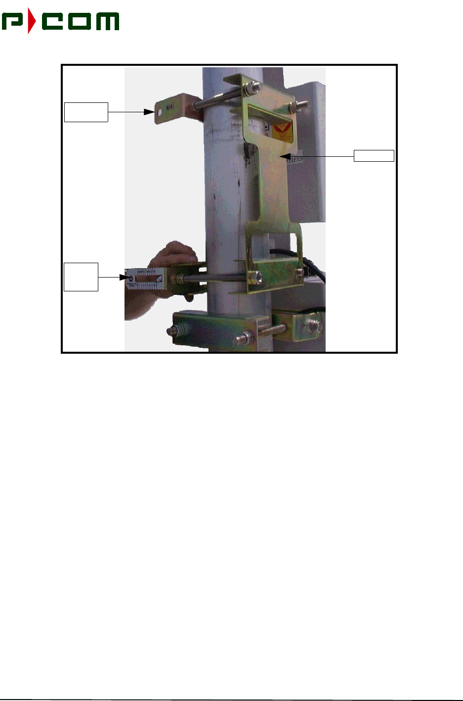
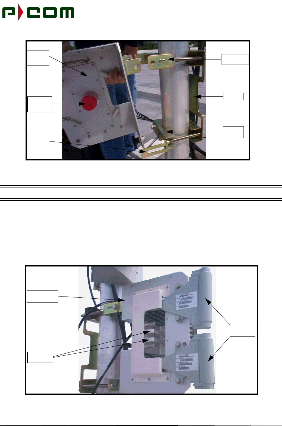
STEP 1. Install the Mounting Bracket on the pole with the elevation adjusting screw either at the
top or bottom of the mount, depending on the desired angle of the Sector Antenna rel-
ative to the Remote sites (refer to Figure 6-1).
November 1999
6-2 M68333 Rev. A Tel-Link PMP - Sector Terminal Installation & Maintenance Manual
Figure 6-1 - Mounting Bracket Assembly
STEP 2. Tighten the four retaining nuts on the backplate of the Mounting Bracket. The backplate
must be positioned such that it is perpendicular to the center point of the desired sector
field of view (refer to Figure 6-1).
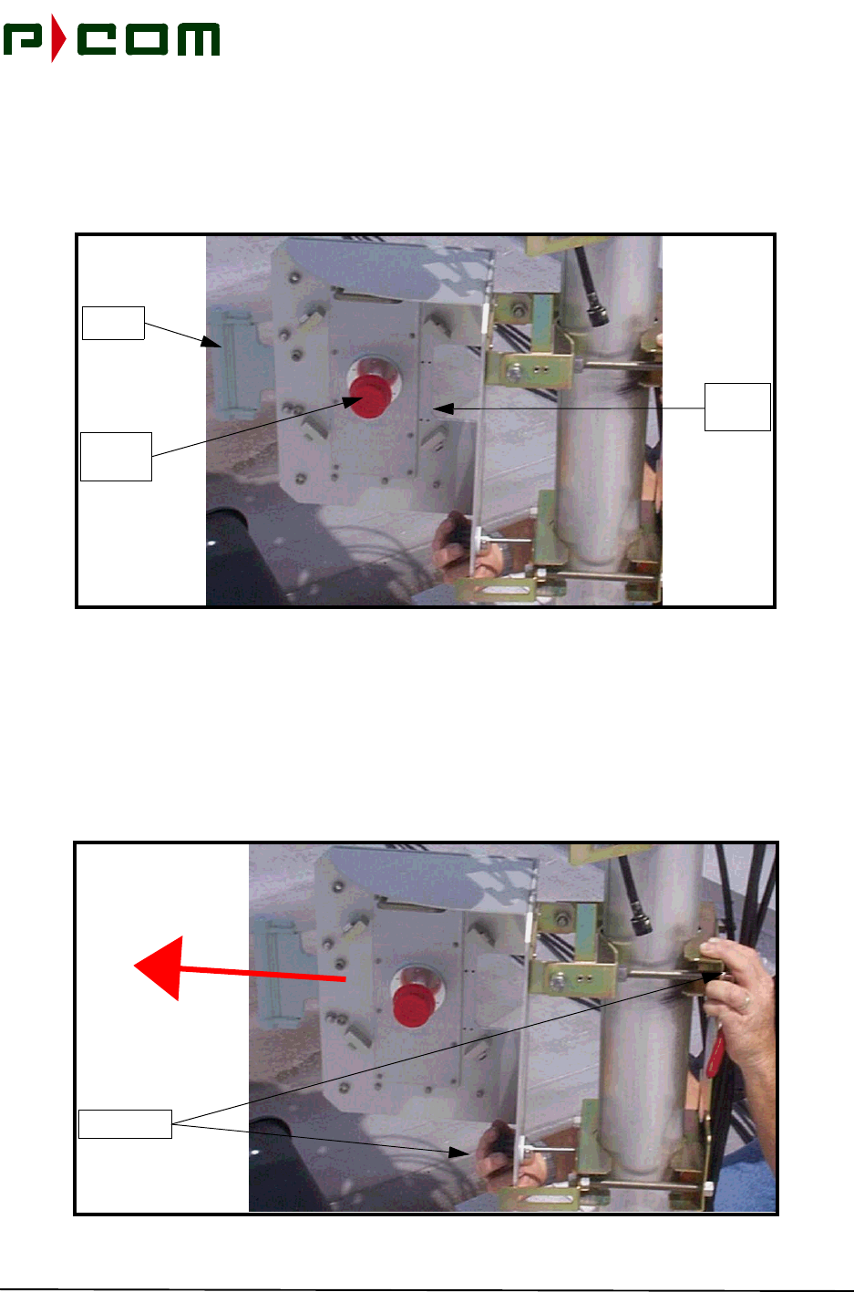
STEP 3. Attach the Antenna Mount Assembly to the Mounting Bracket by securing two bolts at
the pole adaptor assembly. Insert the threaded rod from the pivot assembly into the
Elevation Adjusting Knob. This will control the amount of elevation induced (refer to
Figure 6-2).
Back Plate
Pole Adaptor
Assembly
Elevation
Adjusting
Gauge
November 1999
M68333 Rev. A Tel-Link PMP - Sector Terminal Installation & Maintenance Manual 6-3
Figure 6-2 - Antenna Mount Assembly
NOTE: If installing a 38 GHz system proceed to Step 5
STEP 4. The Antenna Feedhorns are attached to the Antenna Mount Assembly by two bolts
each. Transmit and Receive Feedhorns are attached to the ODU waveguides beneath
the protective cover (refer to Figure 6-3). Use Mylar tape and protective plastic caps to
protect the waveguide orifices to minimize contaminants in the waveguide. Proceed to
Step 6.
Figure 6-3 - Tx and Rx Antenna Feedhorns
Pole Adaptor
Assembly
Backplate
Pivot
Assembly
Antenna
Mount
Assembly
Protection
Cap for
Waveguide
Elevation
Adjusting
Knob
Antenna
Feedhorns
Antenna Mount
Assembly
Tx and Rx
Waveguides
November 1999
6-4 M68333 Rev. A Tel-Link PMP - Sector Terminal Installation & Maintenance Manual
STEP 5. A 38 GHz system utilizes only one Antenna Feedhorn and waveguide and is attached
to the Antenna Mount Assembly by two bolts. Always keep the protective cap in place
when no ODU is attached. This minimizes contaminants in the waveguide (refer to Fig-
ure 6-4).
Figure 6-4 - 38 GHz Antenna Feedhorn
STEP 6. Using binoculars, locate the Remote site locations at both extremes of the sector. Align
the Antenna Feedhorn such that they point in the center of those two locations. A com-
pass should be sufficient to aim the antenna in the desired general direction within ±3°,
taking Magnetic Deviation into consideration when comparing the angle read on the
compass to the desired azimuth angle (refer to Figure 6-5).
Figure 6-5 - Aligning the Sector Antenna
38 GHz
Antenna
Assembly
Antenna
Feedhorn
Waveguide
Protective
Cap
Align to Center
of Sector
November 1999
M68333 Rev. A Tel-Link PMP - Sector Terminal Installation & Maintenance Manual 6-5
STEP 7. Secure the Mounting Bracket retaining nuts once course alignment is complete.
NOTE: If installing a 38 GHz system proceed to Step 10
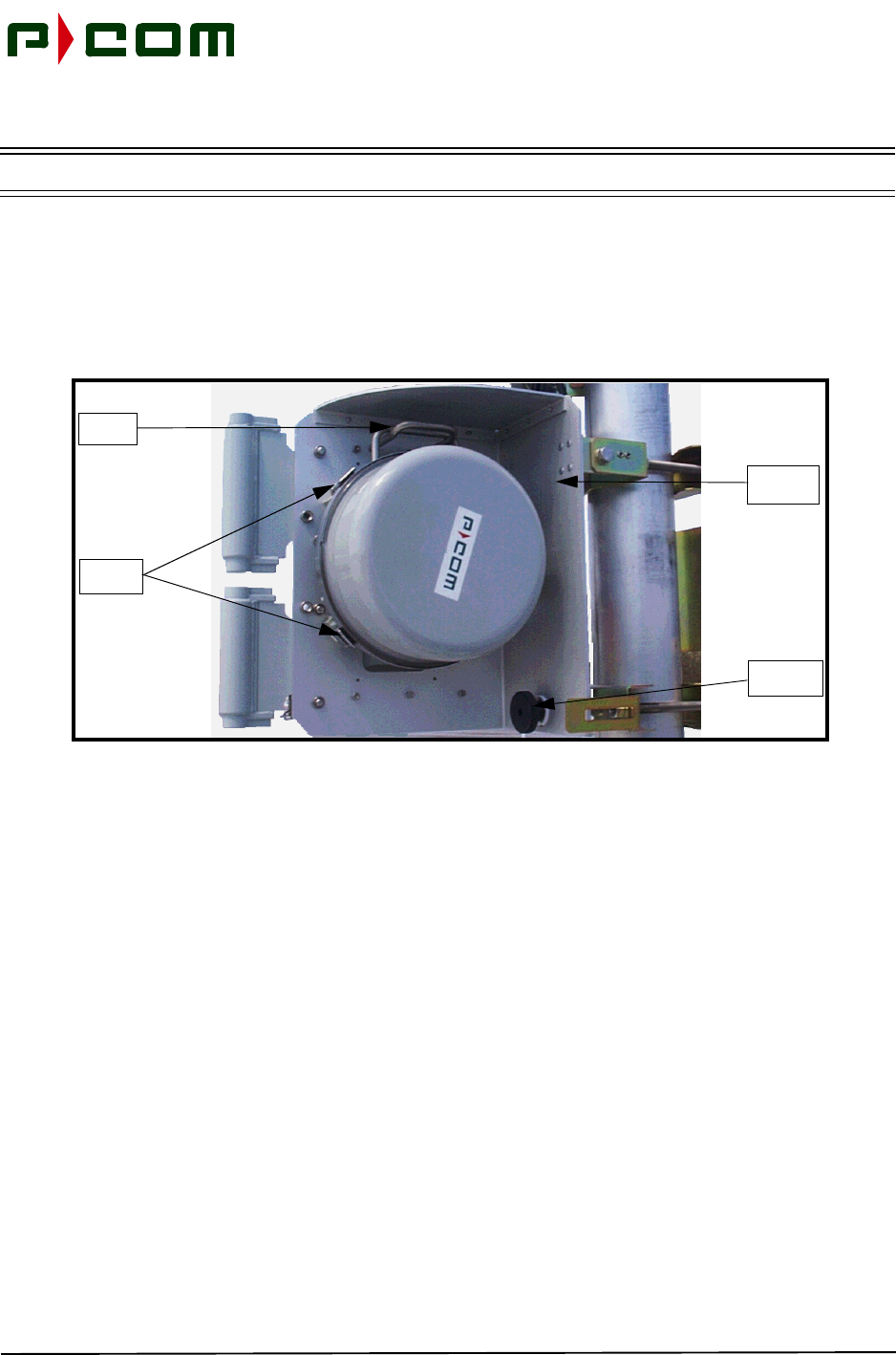
STEP 8. Attach the ODU by positioning it to the back side of the Antenna Mount Assembly with
the help of a protruding supporting handle. Hook the handle and let the ODU hang in
place. Once positioned properly, snap tight the retaining clips mounted on the ODU to
the hook clips of the Antenna Mount Assembly (refer to Figure 6-6).
Figure 6-6 - Attaching ODU to Antenna Mount Assembly
STEP 9. Attach the ODU Tx and Rx waveguide assembly to the appropriate ports on the
Antenna Assembly. The Rx waveguide is the port closest to the center of the ODU.
Thumbscrews, at the antenna end of the waveguide, are used to attach the waveguide
assembly to the Antenna (refer to Figure 6-7)
Antenna
Assembly
Elevation
Adjustment
Support
Handle
Retaining
Clips
November 1999
6-6 M68333 Rev. A Tel-Link PMP - Sector Terminal Installation & Maintenance Manual
Figure 6-7 -.Attaching the Waveguides
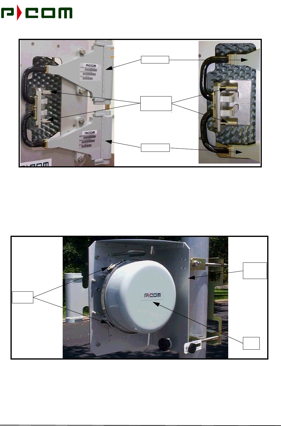
STEP 10. Attach the ODU by seating the circular waveguide into the ODU orifice and positioning
it to the back side of the Antenna Mount Assembly. Once positioned properly, snap
tight the retaining clips mounted on the ODU to the hook clips of the Antenna Mount
Assembly (refer to Figure 6-8).
Figure 6-8 - Attaching 38 GHz ODU to Antenna Mount Assembly
Tx Feedhorn
Rx Feedhorn
Waveguide
Thumbscrews
38 GHz
Antenna
Assembly
Sector
ODU
Retaining
Clips

November 1999
M68333 Rev. A Tel-Link PMP - Sector Terminal Installation & Maintenance Manual 7-1
7.0 Sector Terminal IDU Chassises & ODU Power Supply Chassis
Rack Installation
7.1 Introduction
This procedure provides instructions for installing the Basic and Expansion IDU chassises and the ODU
Power Supply chassis in a standard 19 inch common equipment rack or cabinet. Actual quantity of chas-
sises installed in a rack depends upon space allocation, requirement of expansion IDU chassis, and other
factors. A potential rack layout for both the IDU Chassises and ODU Power Supply in a rack is illustrated in
Figure 7-1.
7.2 Sector IDU Chassis Rack Installation
7.2.1 Tools Required
Refer to Table 3-2 in Section 3.0 for applicable tools.
7.2.2 Materials Required
•Eight (8) cage nuts per Basic IDU Chassis. (May not be required, consult rack manufacturer's
documentation.)
•Eight (8) equipment mounting screws with washers per Basic IDU Chassis. (Consult rack man-
ufacturer's documentation for required size.)
•Eight (8) cage nuts per Expansion IDU Chassis. (May not be required, consult rack manufac-
turer's documentation.)
•Eight (8) equipment mounting screws with washers per Expansion IDU Chassis. (Consult rack
manufacturer's documentation for required size.)
7.2.3 Sector IDU Chassis Rack Installation Procedure
NOTE: P-COM highly recommends that a blower or fan be used with an enclosed rack containing
three or more IDU’s
STEP 1. Install Cage nuts on the rack if necessary
STEP 2. Install the IDU using screws in the eight mounting holes for Basic IDU chassis.
STEP 3. If an Expansion IDU chassis is required, physical installation is similar to the Basic IDU
chassis. Repeat Steps 1 and 2.
November 1999
7-2 M68333 Rev. A Tel-Link PMP - Sector Terminal Installation & Maintenance Manual
Figure 7-1 - Rack Elevation of a Sector Terminal
ODU Power Supply
Chassis #2
5 RU - Blank
Blower, If Required
7 RU - Blank
Expansion IDU
Chassis #1
Basic IDU
Chassis #1
ODU Power Supply
Chassis #1
Expansion IDU
Chassis #2
Basic IDU
Chassis #2

November 1999
M68333 Rev. A Tel-Link PMP - Sector Terminal Installation & Maintenance Manual 7-3
7.3 ODU Power Supply Chassis Rack Installation
7.3.1 Tools Required
Refer to Table 3-2 in Section 3.0 for applicable tools.
7.3.2 Materials Required
•Four (4) cage nuts. (May not be required, consult rack manufacturer's documentation.)
•Four (4) equipment mounting screws with washers. (Consult rack manufacturer's documenta-
tion for required size.)
7.3.3 ODU Power Supply Chassis Rack Installation Procedure
STEP 1. Install Cage nuts on the rack if necessary
STEP 2. Install the ODU Power Supply chassis using screws in the four mounting holes. The
ODU Power Supply chassis is typically mounted above the Basic IDU chassis.

November 1999
7-4 M68333 Rev. A Tel-Link PMP - Sector Terminal Installation & Maintenance Manual
This Page Intentionally Left Blank

November 1999
M68333 Rev. A Tel-Link PMP - Sector Terminal Installation & Maintenance Manual 8-1
8.0 Sector Terminal Wire and Cabling Installation
8.1 Introduction
This procedure provides instructions for wiring and cabling for the Sector IDU chassises, ODU Power Sup-
ply chassis and the ODU. The following shelf wiring is required for full system operations:
•IFL Cabling interconnect (IDU to ODU)
•Power Supply Cabling
•ODU Power Supply Cable (ODU Power Supply to the IDU)
•Grounding
•Expansion IDU chassis wiring (where applicable)
8.2 Ground, Power and Signal Wiring
8.2.1 Tools Required
Refer to Table 3-2 in Section 3.0 for applicable tools.
8.2.2 Material Required
•IFL cable (LMR-400 recommended)
•90° Type-N Adapter
•RF connectors (Type-N)
•Weatherproofing sealant
•Outside Grounding Wire IAW local code
•12 AWG Green Stranded Cable
•12 AWG Compression Ring Lugs
•16 AWG Twisted Pair Cable
•Power Cord (as applicable)

November 1999
8-2 M68333 Rev. A Tel-Link PMP - Sector Terminal Installation & Maintenance Manual
8.2.3 Grounding
NOTE: Ensure the outdoor antenna assembly pole and indoor equipment rack are grounded per
applicable local code.
STEP 1. Ground all IDU chassis using the Chassis Ground screw on the rear of the chassis
(refer to Figure 8-1 and Figure 8-2). Ground the IDU chassises by installing compres-
sion type lug and connecting the lug to the rack frame vertical channel, or local ground-
ing bar, by using 12 AWG (or larger) copper wire. Remove any paint or oxidation from
the surface of the equipment.

November 1999
M68333 Rev. A Tel-Link PMP - Sector Terminal Installation & Maintenance Manual 8-3
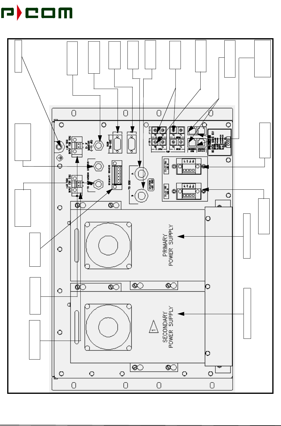
Figure 8-1 - Basic Sector Chassis AC Input (Rear View)
Secondary ODU DC
Power Supply Port
Primary Power Supply
Secondary Power Supply
Primary AC Input
Power Port
Secondary AC
Input Power Port
Chassis Ground
Primary ODU DC
Power Supply Port
Monitor Interface
ATM Ethernet
Interface Ports
Primary IFL
Interface Port
Secondary IFL
Interface Port
Primary NMS
Interface Port
Secondary NMS
Interface Port
Primary
Expansion Chassis
Interface Port
Secondary
Expansion Chassis
Interface Port
Port
Primary ATM
Interface Ports
Secondary ATM
Interface Ports
Summary Alarms
Interface Ports
Expansion Chassis
Ethernet
Interface Ports
November 1999
8-4 M68333 Rev. A Tel-Link PMP - Sector Terminal Installation & Maintenance Manual
Figure 8-2 - Expansion Chassis AC Input (Rear View)
Primary Power Supply
Secondary Power Supply
Primary AC Input
Power Port
Secondary AC
Input Power Port
Chassis Ground
Monitor Interface
ATM Ethernet
Interface Ports
Secondary
Interface Port
Primary NMS
Interface Port
Secondary NMS
Interface Port
Primary
Sector Chassis
Interface Port
Secondary
Sector Chassis
Interface Port
Port
Summary Alarms
Interface Ports
Expansion Chassis
Ethernet
Interface Ports
Chassis
Interface Port
Primary
Interface Port
Chassis
Interface Port
November 1999
M68333 Rev. A Tel-Link PMP - Sector Terminal Installation & Maintenance Manual 8-5
STEP 2. Ground ODU Power Supply chassis using the Chassis Ground stud on the rear of the
power supply (Refer to Figure 8-3). Ground the ODU Power Supply chassis by install-
ing compression type lug and connecting the lug to the rack frame vertical channel, or
local grounding bar, by using 12 AWG (or larger) copper wire. Remove any paint or
oxidation from the surface of the equipment.
Figure 8-3 - Sector ODU Power Supply AC Input (Rear View)
STEP 3. Attach and secure grounding cable, in accordance with local code, from building
ground to the antenna assembly pole structure for proper ODU grounding.
8.2.4 AC Power Supply
DANGER! Before connecting the AC cord to the IDU, ensure that the power switch is turned off.
NOTE: AC power does not apply to ODU wiring.
8.2.4.1 ODU Power Supply Chassis
For AC operations, two standard computer AC power cables rated for 10 Amp capacity are supplied with
each ODU Power Supply chassis. The AC receptacle is found on the rear of the ODU Power Supply chas-
sis (refer to Figure 8-3).
8.2.4.2 Sector IDU Chassises
For AC operations, two standard computer AC power cable rated for 10 Amp capacity are supplied with
each IDU chassis. The AC receptacle is found on the rear of all IDU chassises (refer to Figure 8-1 and Fig-
ure 8-2).
Chassis Ground Stud
Cooling Fan
Primary AC Power
Supply Input Port
Secondary AC Power
Supply Input Port
Secondary DC Power
Supply Output Port Primary DC Power
Supply Output Port
Cooling Fan
November 1999
8-6 M68333 Rev. A Tel-Link PMP - Sector Terminal Installation & Maintenance Manual
8.2.5 DC Power Supply
DANGER! Before connecting the DC cable to the IDU, ensure that the protection fuse is removed to
prevent the application of power at this time.
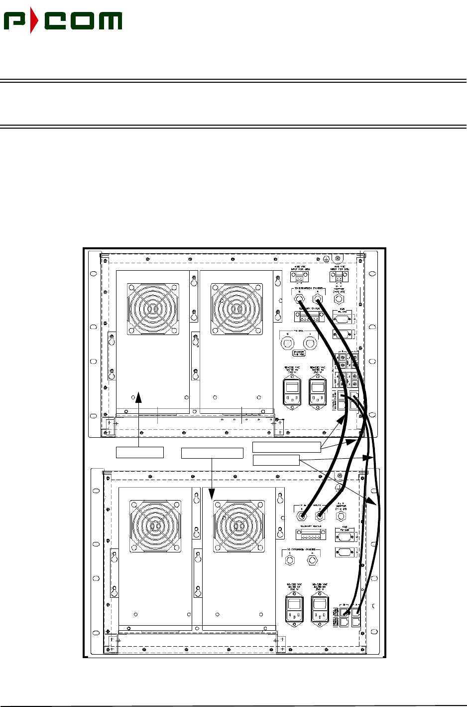
8.2.5.1 ODU Power Supply Chassis
The ODU receives its power from the ODU Power Supply chassis via the Basic IDU chassis through an IFL
cable and may be measured at the center pin of the IFL when connected to the IDU Chassis (refer to Figure
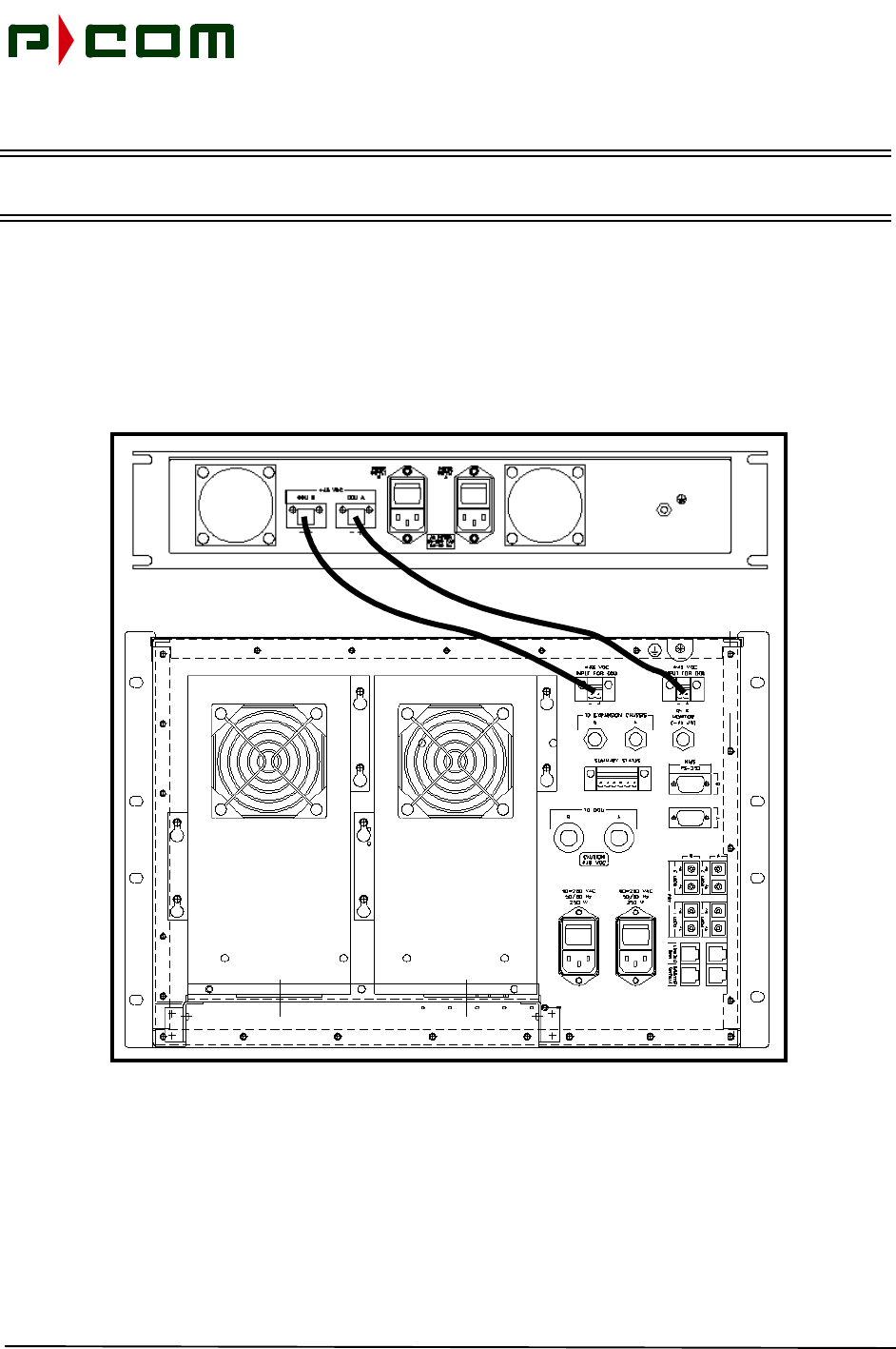
8-4).
Figure 8-4 - Interconnecting of the ODU Power Supply to the Sector IDU
November 1999
M68333 Rev. A Tel-Link PMP - Sector Terminal Installation & Maintenance Manual 8-7
For DC operations, 16 AWG, 2-conductor twisted pair cable is supplied. The cables for carrying DC power
to the ODU Power Supply chassis should be routed to a DC distribution panel preferably installed in the
same rack. The DC distribution panel should provide individual fuse protection to each chassis. The DC
receptacle is found on the rear of the ODU Power Supply chassis (refer to Figure 8-5). The DC power to the
ODU Power Supply chassis should be protected with a 5.0 Amp fuse.
Figure 8-5 - Sector ODU Power Supply DC Input (Rear View)
8.2.5.2 Sector IDU Chassises
For DC operations, 12 AWG, 2-conductor cable is supplied. The cables for carrying DC power to the Sector
IDU should be routed to a DC distribution panel preferably installed in the same rack. The DC distribution
panel should provide individual fuse protection to each chassis. The DC receptacle is found on the rear of
the IDU (refer to Figure 8-6). The DC power to the Sector Terminal should be protected with a 5.0 Amp
fuse.
Chassis Ground Stud
Cooling Fan
Primary DC Power
Supply Input Port
Secondary DC Power
Supply Input Port
Secondary DC Power
Supply Output Port Primary DC Power
Supply Output Port
Cooling Fan
November 1999
8-8 M68333 Rev. A Tel-Link PMP - Sector Terminal Installation & Maintenance Manual
Figure 8-6 - Basic Sector Chassis DC Input (Rear View)
Secondary ODU DC
Power Supply Port
Primary Power Supply
Secondary Power Supply
Primary DC Input
Power Port
Secondary DC
Input Power Port
Chassis Ground
Primary ODU DC
Power Supply Port
Monitor Interface
ATM Ethernet
Interface Ports
Primary IFL
Interface Port
Secondary IFL
Interface Port
Primary NMS
Interface Port
Secondary NMS
Interface Port
Primary
Expansion Chassis
Interface Port
Secondary
Expansion Chassis
Interface Port
Port
Primary ATM
Interface Ports
Secondary ATM
Interface Ports
Summary Alarms
Interface Ports
Expansion Chassis
Ethernet
Interface Ports
November 1999
M68333 Rev. A Tel-Link PMP - Sector Terminal Installation & Maintenance Manual 8-9
8.2.6 IFL Cabling
WARNING! Do not plug the IDU into the AC outlet or DC power source until the cable to the ODU is
connected. If power is on, a DC voltage (44 VDC) will be present on the N connector of the
IDU and could be shorted when installing the coaxial cable to the ODU.
If an Expansion IDU Chassis is being installed connect it to the Basic IDU Chassis via an IF cable (RG-58)
50-ohm, coaxial cable with male BNC connectors and UTP-5 Cable (refer to Figure 8-7). The length of the
cable should be sufficient to allow a small service loop near each end and shall not exceed 20 ft (6 meters).
When connecting the Basic IDU Chassis to the ODU, sufficient length of cable should be used to allow rout-
ing along the side of the rack, and a service loop. Perform the following steps to complete IF Cabling (refer
to Figure 8-1).
Figure 8-7 - Basic Chassis Connection to Expansion Chassis (Rear View)
RG-58 Coaxial Cable
Basic Chassis Expansion Chassis UTP-5 Cable

November 1999
8-10 M68333 Rev. A Tel-Link PMP - Sector Terminal Installation & Maintenance Manual
STEP 1. Terminate IF Cable ends with Type-N Male RF connectors
STEP 2. Connect one end of the RG-58 coaxial cable to the Primary Sector Chassis Interface
Port of the Expansion IDU chassis to the Primary Expansion Chassis Interface Port of
the Basic IDU chassis. Connect one end of the RG-58 coaxial cable to the Secondary
Sector Chassis Interface Port of the Expansion IDU chassis to the Secondary Expan-
sion Chassis Interface Port of the Basic IDU chassis.
STEP 3. Connect the Primary IFL cable to the Primary IFL Interface Port on the Sector IDU
STEP 4. Ensure a 90° Type-N Adapter is securely attached to the ODU Type-N female port
STEP 5. Connect the IF cable to the 90° Type-N Adapter of the ODU and apply Weatherproof-
ing sealant
STEP 6. Connect one end of the Primary UTP-5 cable to the Primary Expansion Chassis Ether-
net Interface Port of the Basic Chassis to the Primary Expansion Chassis Ethernet
Interface Port of the Expansion Chassis. Connect one end of the Secondary UTP-5
cable to the Primary Expansion Chassis Ethernet Interface Port of the Basic Chassis to
the Secondary Expansion Chassis Ethernet Interface Port of the Expansion Chassis.
8.3 IDU to NMS and CPE Cabling
8.3.1 Tools Required
Refer to Table 3-2 in Section 3.0 for applicable tools.
8.3.2 Material Required
•Serial, straight-through, computer cable with DB-9 male/female connectors, 15-25 ft in length
8.3.3 NMS Cabling
STEP 1. Connect the NMS serial cable to the NMS Interface Port located in the rear of all IDU
chassis (refer to Figure 8-1 and Figure 8-2). Screw down the connector to the NMS
Interface Port to maintain secure connection.
STEP 2. Connect ATM Interface Port cables to customer supplied equipment, e.g., ATM Switch.
November 1999
M68333 Rev. A Tel-Link PMP - Sector Terminal Installation & Maintenance Manual 9-1
9.0 Sector Terminal IDU Board Installation
9.1 Introduction
The Basic IDU chassis consists of a power supply module(s), Modulators, Demodulators (FDMA network),
Burst Demodulators (TDMA network), Sector ATM Controllers and ODU MUXs. The Expansion IDU chas-
sis consists of Demodulators (FDMA), Demodulators (TDMA), Sector Expansion Controllers, and Receive
IF Demultiplexers. The Sector IDU is designed to avoid single points of failure and ease of replacement of
failed components. These cards are hot pluggable/swappable and can be configured for redundant opera-
tions as shown in Table 9-1 and Table 9-2. The Expansion chassis provides expansion of additional FDMA
and TDMA Demodulator boards for larger sectors (Refer to Figure 3-1).
.
WARNING! Precautions for anti-static protection should be taken whenever handling printed circuit
boards. Circuit modules can be damaged by electrostatic discharge. Ensure that an
approved anti-static wrist strap is connected between the wrist of the person and an
electrical ground before handling any of the circuit modules.
Placement of the common equipment boards within the IDU chassis is critical, and should follow the layout
as shown in Figure 9-1 and Figure 9-2. Insert the boards from left to right for each board type
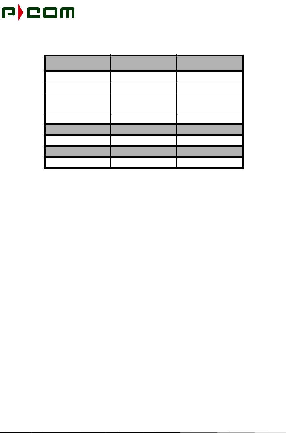
Table 9-1 - Basic IDU Chassis Redundancy
Name Ratio Description
Modulator 1:5 5 online Modulators, 1 Redundant
Demodulator 1:10 10 online Demodulators, 1 Redundant
Controller 1:1 1 online Controller, 1 Redundant
ODU Multiplexer 1:1 1 online ODU MUX, 1 Redundant
IDU Power Supply 1:1 1 online Power Supply, 1 Redundant
Table 9-2 - Expansion IDU Chassis Redundancy
Name Ratio Description
Demodulator 1:15 15 online Demodulators, 1 Redundant
Controller 1:1 1 online Controller, 1 Redundant
RX IF Demultiplexer 1:1 1 online ODU MUX, 1 Redundant
IDU Power Supply 1:1 1 online Power Supply, 1 Redundant
November 1999
9-2 M68333 Rev. A Tel-Link PMP - Sector Terminal Installation & Maintenance Manual
Figure 9-1 - Basic IDU Chassis Board Placement
Figure 9-2 - Expansion IDU Chassis Board Placement
SAC
SAC
MOD MOD
MODMOD MOD DEMOD
DEMODDEMOD
MUX
MUX
MOD DEMOD DEMOD
DEMOD
DEMOD
DEMOD
DEMOD
DEMOD
DEMOD
SEC
SEC DEMOD
DEMOD
DEMOD DEMOD
DEMOD
DEMOD
DEMOD
DEMOD
DEMOD
DEMODDEMOD
DEMOD
DEMOD
DEMOD
DEMOD
DEMOD
DEMOD DEMUX
DEMUX
November 1999
M68333 Rev. A Tel-Link PMP - Sector Terminal Installation & Maintenance Manual 9-3
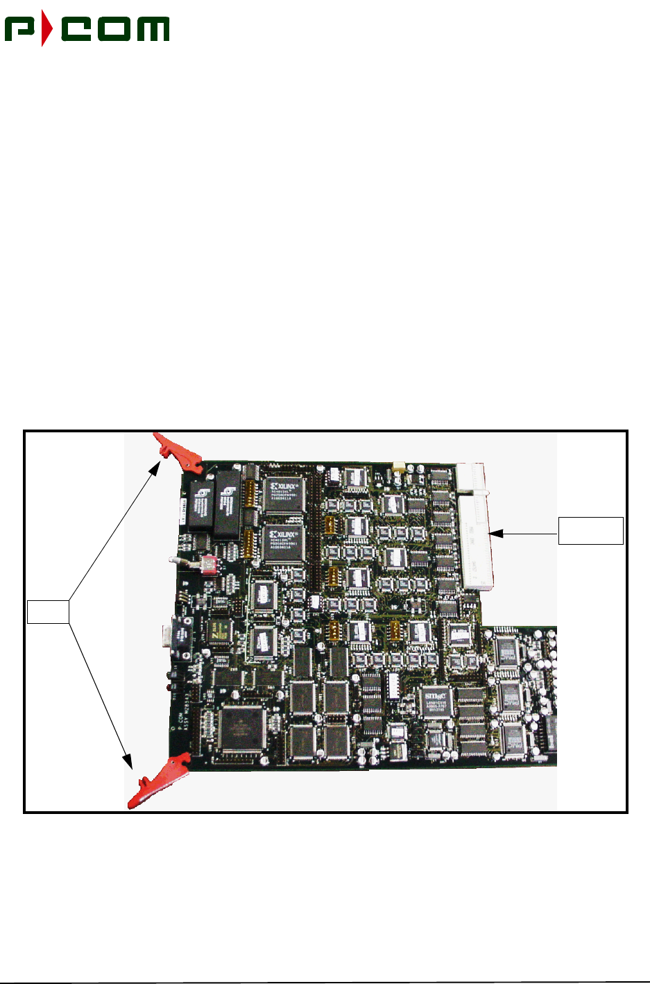
9.2 Board Installation
The printed circuit board has a high-density connector on one edge of the board and two black tabs on the
opposite edge of the board (refer to Figure 9-3). Within the chassis, a board slot consists of nylon guides
located at the top and bottom of a board slot, and a high density mating connector located on the mother-
board within the chassis. Refer to Table 5-1, Sector IDU Parts List, for part numbers of the appropriate
cards.
STEP 1. To insert a printed circuit board, vertically align the printed circuit board with the board
slot of the chassis. The majority of the components on the printed circuit board should
be facing towards the right of the chassis. The high-density connector located on the
printed circuit board is inserted into the chassis first, orientated to allow mating with the
corresponding high-density receptacle on the motherboard within the chassis.
STEP 2. The two colored tabs on the front edge of the board are to be held in an extended ori-
entation. Slide the board into the chassis, along the guides, until the two high-density
connectors are close to mating. Use the grips of the black tabs to attach to the chassis
frame, pressing the tabs towards the printed circuit board edge, making a secure con-
nection with the two high-density connectors.
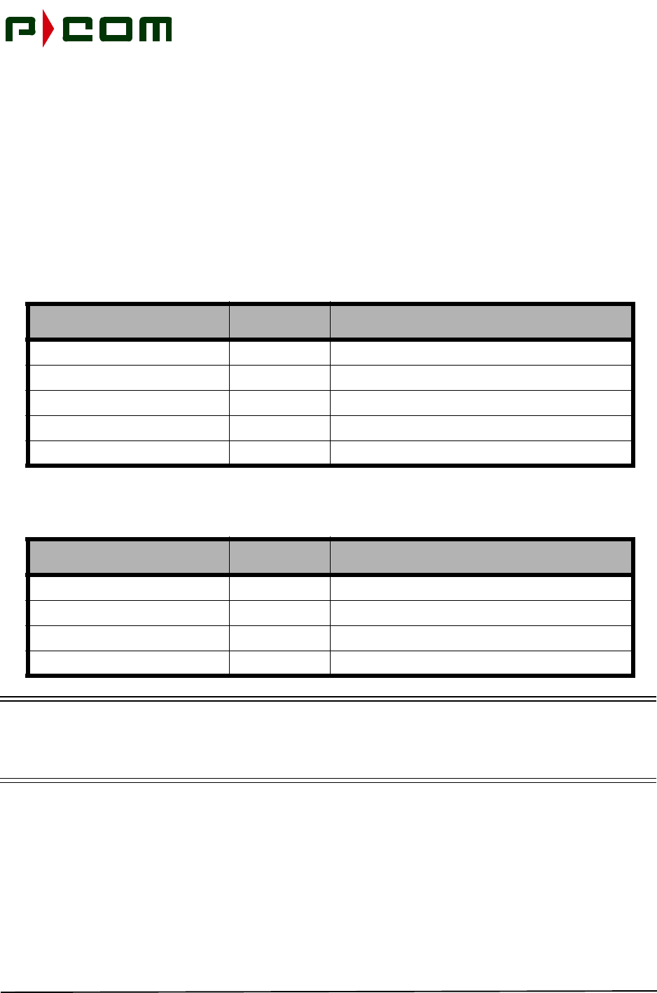
Figure 9-3 - Example of Printed Circuit Board
High-Density
Connector
Colored
Tabs
November 1999
9-4 M68333 Rev. A Tel-Link PMP - Sector Terminal Installation & Maintenance Manual
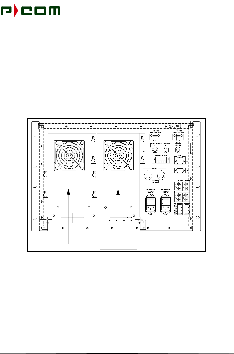
9.3 Power Supply Installation
The power supply is mounted on the rear of all IDU chassis in the right receptacle as seen from the rear
(refer to Figure 9-4). If redundant power supplies are used the secondary unit is mounted in the left recepta-
cle as seen from the rear.
STEP 1. Position the power supply on the rear of the IDU such that the retaining screws pro-
trude through the four (4) mounting openings of the power supply box.
STEP 2. Slide the power supply down so the multi-pin connector on the bottom of the power
supply mates with the opposite connector on all IDU chassis.
STEP 3. Secure the four (4) retaining screws to all IDU chassis.
Figure 9-4 - Basic Sector Chassis (Rear View)
9.4 Board Removal
STEP 1. To remove a printed circuit board, grab the two tabs on the edge of the printed circuit
board (refer to Figure 9-3). Extending these tabs will separate the printed circuit board
high-density connector from its mate within the chassis. Slide the printed circuit board
out of the chassis to complete the removal.
Primary Power Supply
Secondary Power Supply

November 1999
M68333 Rev. A Tel-Link PMP - Sector Terminal Installation & Maintenance Manual 9-5
9.5 Power Supply Removal
STEP 1. Loosen the four (4) retaining screws that secure the power supply to the IDU chassis.
STEP 2. Slide the power supply out to disconnect it from the IDU chassis.

November 1999
9-6 M68333 Rev. A Tel-Link PMP - Sector Terminal Installation & Maintenance Manual
This Page Intentionally Left Blank

November 1999
M68333 Rev. A Tel-Link PMP - Sector Terminal Installation & Maintenance Manual 10-1
10.0 Sector Terminal Initial Power Application
10.1 DC Power Application
STEP 1. Ensure the DC connector to the Sector IDU and ODU Power Supply are not con-
nected.
STEP 2. Verify the appropriately sized fuses are installed IAW procedures in Section 8.0. Two
fuses may be used for optional redundant power supply configuration.
STEP 3. Plug in the DC connector into the DC Power Port of the Sector IDU and ODU Power
Supply. The right-most DC Input Power Port should be used first.
STEP 4. Verify power is applied to the chassis by viewing the LEDs on the front panel.
STEP 5. If the LEDs on the boards do not illuminate, remove the DC connector from the appro-
priate equipment and verify wiring and voltage polarity.
10.2 AC Power Application
STEP 1. Ensure the AC power switch of the Sector IDU and ODU Power Supple are in the OFF
position.
STEP 2. Plug the AC cord for the Sector IDU and ODU Power Supply into the AC source. The
right-most DC Input Power Port should be used first.
STEP 3. Place the AC power switch on the Sector IDU and ODU Power Supply in the ON posi-
tion.
STEP 4. Verify power is applied to the chassis by viewing the LEDs on the front panel.
STEP 5. If the LEDs on the boards do not illuminate, remove the AC connector from the appro-
priate equipment and verify wiring and AC voltage.

November 1999
10-2 M68333 Rev. A Tel-Link PMP - Sector Terminal Installation & Maintenance Manual
This Page Intentionally Left Blank
November 1999
M68333 Rev. A Tel-Link PMP - Sector Terminal Installation & Maintenance Manual 11-1
11.0 Initial Terminal Configuration and Testing
Proper functioning of this command and response exchange verifies that the IDU’s Local Site Manager
(LSM) agent and other critical software components are present and operational. Refer to the Tel-Link PMP
- Local Site Manager Users Manual No.M68331 for detailed information on LSM operations. From the PC,
the installer can use the Get and Set commands to communicate with the LSM agent in the IDU to program
and interrogate the IDU configuration. Completion of the configuration will ensure items are properly
loaded.
11.1 Terminal Configuration
STEP 1. After applying power to the IDU, allow the unit to warm up for five minutes.
STEP 2. Verify that each card has completed its self-test process and the LEDs on the front of
each card are in a operational state. (Refer to Table 11-1).
Table 11-1 - Board LED Indications
BOARD LED COLOR INDICATION DESCRIPTION
Modulator Green Blinking Operational
Off or Solid On Fault
Red Solid On Fault
Off Operational
Demodulator Green Blinking Operational
Off or Solid On Fault
Red Solid On Fault
Blinking Link Acquisition Mode
Off Operational
Sector ATM
Controller Green Blinking Operational
Off Fault
Red Solid On Fault
Blinking Frequencies Incorrectly
Configured
Off Operational
ODU MUX Green Blinking Operational
Off or Solid On Fault
Red Solid On DC removed from ODU
Off Operational
November 1999
11-2 M68333 Rev. A Tel-Link PMP - Sector Terminal Installation & Maintenance Manual
STEP 3. Connect the LSM to the LSM Interface Port of the Sector ATM Controller Card (refer to
Figure 11-1). Connection is via a straight through cable with Male/Female DB-9 con-
nections. The LSM should be running the P-COM WaveView software.
Figure 11-1 - LSM Interface Port of the Sector ATM Controller Card
STEP 4. Verify appropriate software is loaded in the Controller and in accordance with the Sys-
tem Configuration Document.
STEP 5. Verify the transmitter is disabled.
STEP 6. Sector Terminal Set the sac_Commissioning_Complete register to
No.
STEP 7. Load (Set and Get) appropriate registers in the IDU. Refer to the System Configuration
Document for appropriate frequencies, data rates, modulation schemes, etc. The icon
to the left of each of the configuration item's name should have a green plus symbol to
indicate successful loading of each configuration parameter.
RF IF DEMUX Green Blinking Operational
Off Fault
Red Solid On Fault
Off Operational
Table 11-1 - Board LED Indications
BOARD LED COLOR INDICATION DESCRIPTION
LSM Interface Port
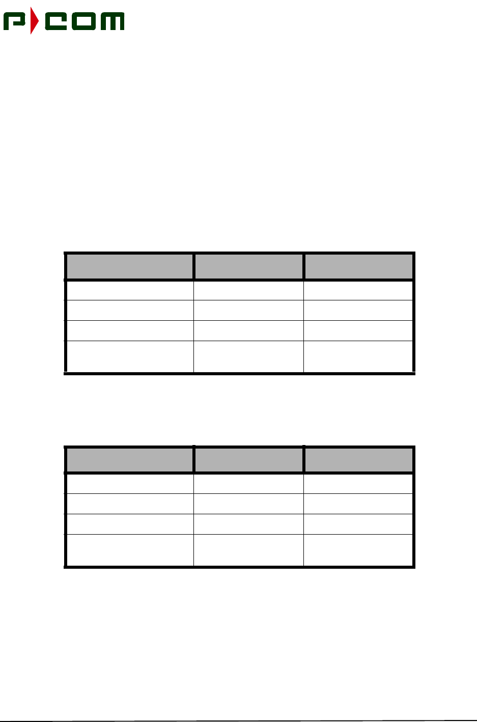
November 1999
M68333 Rev. A Tel-Link PMP - Sector Terminal Installation & Maintenance Manual 11-3
11.2 Antenna Alignment
STEP 1. Enable the transmitter
• Set the sc_Commissioning_Complete register to Yes.
11.3 Terminal Commissioning
11.3.1 LED Functionality
The following steps will verify the functionality of the LEDs of each board of the Sector IDU:
STEP 1. Verify the LEDs are in the following state:
STEP 2. Turn off the Toggle Switch on the ODU Mux and verify the following LED state
occurred:
BOARD GREEN LEDs RED LEDs
Sector ATM Controller Blinking Off
Modulator Blinking Off
ODU Mux Blinking Off
Demodulator Blinking Off
BOARD GREEN LEDs RED LEDs
Sector ATM Controller Blinking Off
Modulator Blinking Off
ODU Mux Blinking Off
Demodulator Blinking Blinking

November 1999
11-4 M68333 Rev. A Tel-Link PMP - Sector Terminal Installation & Maintenance Manual
STEP 3. Turn on the Toggle Switch on the ODU Mux and verify the following LED state
occurred:
STEP 4. From the LSM initiate a software reset for the SAC by setting sac_Reset parameter to
Software_Reset and then right clicking on sac_Reset and selecting Set. Verify the fol-
lowing LED state changes occur. This action should not interrupt customer traffic:
STEP 5. From the LSM initiate a hardware reset for the SAC by setting sac_Reset parameter to
Hardware_Reset and then right clicking on sac_Reset and selecting Set. Verify the
following LED state changes occur. This action will interrupt customer traffic, causing
all Sector IDU boards to temporarily display red LEDs, then resuming their nominal
state. The system will recover within 60 seconds:
BOARD GREEN LEDs RED LEDs
Sector ATM Controller Blinking Off
Modulator Blinking Off
ODU Mux Blinking Off
Demodulator Blinking Off
BOARD GREEN LEDs RED LEDs
Sector ATM Controller Blinking Blinking first then Off
Modulator Blinking Off
ODU Mux Blinking Off
Demodulator Blinking Off
BOARD GREEN LEDs RED LEDs
Sector ATM Controller Blinking Blinking first then Off
Modulator Blinking Blinking first then Off
ODU Mux Blinking Blinking first then Off
Demodulator Blinking Blinking first then Off
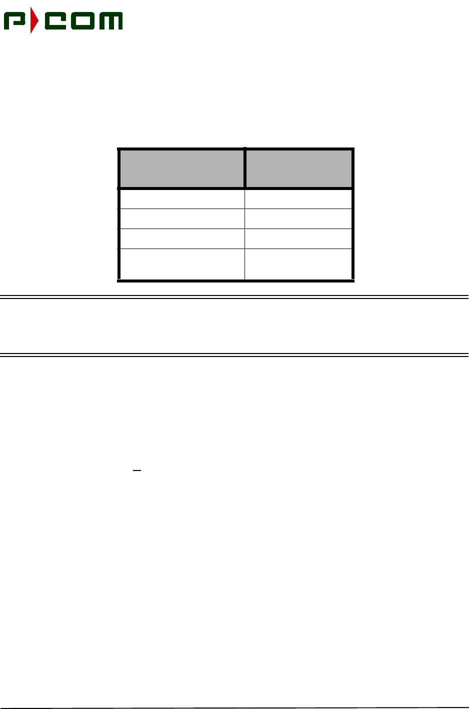
November 1999
M68333 Rev. A Tel-Link PMP - Sector Terminal Installation & Maintenance Manual 11-5
11.3.2 Hot Swap/Redundancy Test
The following steps will demonstrate the “Hot Swap” and redundancy features of the Sector IDU. Boards
will become functional when inserted into a powered chassis. A functional redundant board automatically
replaces a simulated board failure with the time frame listed below:
NOTE: The Sector IDU Chassis shall be equipped with a non-redundant set of boards and has
achieved an operational state. A communications link between a Sector and Remote
Terminals shall be established with the Remote Terminal configured in a network loopback
state.
11.3.2.1 Sector ATM Controller (SAC)
STEP 1. Insert a SAC board into the secondary SAC slot and allow the SAC to undergo its self-
test functions. Verify the secondary SAC is configured as the spare unit.
STEP 2. Pull the primary SAC board.
STEP 3. Initiate a Get All command on the SAC Section. The SAC Chassis Window should
refresh with configuration parameters and the following will occur:
• The redundant SAC board will show the configuration parameters of the “Failed” pri-
mary board.
• The Red LED on the redundant SAC board will extinguish.
• The link to the Remote Terminal will lose lock and then reacquire within 10 seconds
SECTOR IDU
BOARD RECOVERY
TIME
Sector ATM Controller < 15 Seconds
Modulator < 15 Seconds
ODU Mux < 10 Seconds
Demodulator < 15 Seconds

November 1999
11-6 M68333 Rev. A Tel-Link PMP - Sector Terminal Installation & Maintenance Manual
11.3.2.2 Modulators
STEP 1. Insert a Modulator board into one of the empty modulator slots and allow the Modulator
to undergo its self-test functions. Configure the secondary Modulator as the spare unit.
STEP 2. Pull the primary Modulator board.
STEP 3. Initiate a Get All command on the MOD Section. The Mod Chassis Window should
refresh with configuration parameters and the following will occur:
• The Red LED on the redundant Modulator board will extinguish.
• The link to the Remote Terminal will lose lock and then reacquire within 15 seconds
11.3.2.3 ODU Mux
STEP 1. Insert an ODU Mux board into the empty ODU Mux slot and allow the ODU Mux to
undergo its self-test functions. Configure the secondary ODU Mux as the spare unit.
NOTE: Spare ODU must be connected.
STEP 2. Pull the primary ODU Mux board.
STEP 3. Initiate a Get All command on the ODU MUX Section. The ODU MUX Chassis Window
should refresh with configuration parameters and the following will occur:
• The Red LED on the redundant ODU Mux board will extinguish.
• The link to the Remote Terminal will lose lock and then reacquire within 15 seconds
11.3.2.4 FDMA Demodulators
STEP 1. Insert a Demodulator board into one of the empty Demodulator slots and allow the
Demodulator to undergo its self-test functions. Configure the secondary Demodulator
as the spare unit.
STEP 2. Pull the primary Demodulator board.
STEP 3. Initiate a Get All command on the DEMOD Section. The DEMOD Chassis Window
should refresh with configuration parameters and the following will occur:
• The redundant Demodulator board will show the configuration parameters of the
“Failed” primary board.
• The Red LED on the redundant Demodulator board will extinguish.
• The link to the Remote Terminal will lose lock and then reacquire within 15 seconds

November 1999
M68333 Rev. A Tel-Link PMP - Sector Terminal Installation & Maintenance Manual 11-7
11.3.3 Power-up Restoration
The following steps will ensure the PMP equipment will restore back to an operational state with the inter-
ruption of power:
STEP 1. Connect an ATM Test Set to the Sector Physical Port. Place an ATM Port of the
Remote IDU into an ATM mode and the ATM Test Set will generate ATM packets.
STEP 2. Allow the system to stabilize into an operational state and turn the power off to the Sec-
tor Terminal. The ATM Test Set should be displaying bit/packet errors.
STEP 3. Reapply power to the Sector Terminal. After approximately one minutes, the bit/packet
errors displayed on the ATM Test Set should halt.
11.3.4 ATM Connectivity (End-to-End) Test
The following steps will verify end-to-end ATM connection has been established between a Sector and
Remote Terminal:
STEP 1. Provision, with the ATM Test Set, a CBR connection with the appropriate VPI/VCI
between the ATM switch and the Remote IDU.
STEP 2. Place the Remote IDU under test into ATM Loopback.
STEP 3. Reset the ATM Test Set and allow the test to run for 5 minutes.
STEP 4. Verify the equipment can handle the traffic with no cell loss.
STEP 5. Perform tests on all ports.

November 1999
11-8 M68333 Rev. A Tel-Link PMP - Sector Terminal Installation & Maintenance Manual
This Page Intentionally Left Blank

November 1999
M68333 Rev. A Tel-Link PMP - Sector Terminal Installation & Maintenance Manual 12-1
12.0 Technical Support
12.1 Warranty
P-COM warrants PMP products to be free from defects in materials and workmanship for a period of twelve
(12) months from the date of shipment from the factory. Extended warranty options are available.
12.2 Return Process
The boards of the PMP product requiring service may be sent to P-COM Florida at any time whether the
unit is under warranty or not. There is a charge for repairs after the twelve-month warranty period.
A product requiring service should be returned with a Return Material Authorization (RMA), a detailed
description of the problem and proof of purchase date if the twelve-month warranty has not expired. The
product should be returned in its original shipping carton to ensure that in-transit damage does not occur.
The following process is used whenever returning equipment to P-COM:
STEP 1. Contact P-COM TAC at the telephone number below to obtain an RMA number and
return shipping address:
P-COM Technical Assistance Center
Phone Number:1-877-674-3600
FAX Number:1-407-674-3700
Hours of Operation
8:00 AM to 5:00 PM Eastern Time (standard or daylight savings)
NOTE: All equipment received without an RMA will be returned to the sender.
STEP 2. Pack the equipment in the original shipping containers, if possible. If original shipping
containers have been discarded, pack the failed unit so as to protect it from shipping
damage.
STEP 3. Obtain insurance from the shipper that will cover the entire value of the equipment
being returned.
STEP 4. Send the equipment (pre-paid shipping) to the address received from the Technical
Assistance Center.
STEP 5. P-COM will notify the sender, upon receipt of the equipment, of an estimated time to
repair and for return shipping instructions. An estimate of the repair cost will be given
for all non-warranty repairs
All repairs covered under warranty will be completed at no cost and the return shipping (surface) will be
paid for by P-COM. Repairs not covered by the warranty will be performed at current P-COM labor rates
and material costs and billed to the customer. In addition, shipping will be billed for non-warranty repairs.

November 1999
12-2 M68333 Rev. A Tel-Link PMP - Sector Terminal Installation & Maintenance Manual
This Page Intentionally Left Blank

November 1999
M68333 Rev. A Tel-Link PMP - Sector Terminal Installation & Maintenance Manual A-1
APPENDIX A: PMP Installation Procedure Checklist
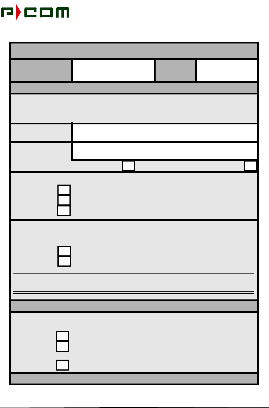
November 1999
A-2 M68333 Rev. A Tel-Link PMP - Sector Terminal Installation & Maintenance Manual
PMP INSTALLATION PROCEDURE CHECKLIST
Technician(s)
Name: Date:
INTRODUCTION
This Installation Procedure Checklist is provided to ensure correct installation procedures of P-COM PMP
equipment. The Checklist is to be completed for each site installed and the installer is to check-off each
step as completed. The installer will sign and date the Checklist and forward it to the P-COM Technical
Assistance Center (TAC) when the installation is completed.
Site Name:
Site Designation:
Sector Terminal Remote Terminal
FORMS:
Verify possession of completed Site Survey Form for the designated site.
Verify possession of System Configuration Document for the designated site.
Verify possession of Commissioning Test Form for the designated site.
INVENTORY:The shipping list contains all equipment ordered by the customer for the total
number of Sector and Remote Terminals.
Verify possession of completed Site Survey Form for the designated site.
Verify possession of System Configuration Document for the designated site.
NOTE: Any visible damage should be reported immediately to the customer and to P-COM TAC
at: 1-(877) 674-3600
INTERFACILITY LINK (IFL) INSTALLATION SEQUENCE
IFL INSTALLATION
PREPARATION: The IFL should be Times-Microwave LMR-400 coaxial cable, or equiv-
alent, unless otherwise stated in the P-COM Site Survey Form
Verify presence of an appropriate IFL between ODU and IDU locations.
Verify sufficient length (4 ft) of IFL exists at both ends to provide a service loop
prior to being terminated to the equipment.
Terminate each end of the IFL with Type-N male connectors.
Page 1 of 5
November 1999
M68333 Rev. A Tel-Link PMP - Sector Terminal Installation & Maintenance Manual A-3
OUTDOOR UNIT (ODU) INSTALLATION SEQUENCE
ODU/ANTENNA
INSTALLATION
PREPARATION:
Verify the pole used to mount the ODU/Antenna assembly is installed at the
location identified in the SIte Survey Form.
Verify the pole is securely mounted and connected to earth ground in accor-
dance with local code.
ODU/ANTENNA
INSTALLATION:
Install the ODU/Antenna assembly in accordance with the P-COM Installation
and Maintenance Manual.
Sector ODU/Antenna: Course align the antenna in the direction for operation
as specified in the P-COM System Configuration Document.
Remote ODU/Antenna: Align the antenna in the general direction of the desig-
nated Sector Terminal. Fine-tuning will be performed during the “Initial Power-
up and Test Sequence.”
ODU
INTERCONNECT:
Sector Terminal: Connect the IFL cable between the appropriate ODU and
Basic IDU Chassis.
Remote Terminal: Connect the IFL cable between the ODU RF Port (Type-N
Connector and Remote IDU.
INDOOR UNIT (IDU) INSTALLATION SEQUENCE
IDU INSTALLATION
PREPARATION: Each Site should be identified, In the P-COM Site Survey Form, if the
IDU is to be rack mounted or placed on a tabletop.
Verify presence of IDU chassis and all cards intended to populate the IDU.
Verify presence of customer’s interface demarcation
Verify required rack/table is installed, secured to the floor, and ready to accept
the IDU.
Verify correct power source has bee provided within close proximity to the
location where the IDU is to be installed and is controlled through an appropri-
ate sized circuit breaker or fuse
Verify power to the IDU is in the Off position (AC) or disconnected (DC).
Page 2 of 5
PMP INSTALLATION PROCEDURE CHECKLIST
Technician(s)
Name: Date:
November 1999
A-4 M68333 Rev. A Tel-Link PMP - Sector Terminal Installation & Maintenance Manual
IDU
INSTALLATION:
Properly install the IDU in accordance with P-COM Installation & Maintenance
Manual.
IDU
INTERCONNECT:
Sector Terminal: Connect the IFL cable to the RF Port of the IDU.
Remote Terminal: Connect the IFL cable to the RF Port of the IDU.
Sector and Remote Terminals: Connect the power leads/cords to the IDU Input
Power Port. Terminate the power leads/cord to the appropriate AC or DC
power source. Two power leads/cable may be terminated for a Sector IDU with
optional redundant power supplies.
Sector and Remote IDUs: Connect a ground wire from the chassis to a local
earth ground.
CUSTOMER
PREMISE EQUIP-
MENT (CPE)
PREPARATION:
Verify CPE has been installed within close proximity to the IDU equipment.
Verify sufficient length of CPE cable is present to provide a service loop prior to
being terminated to the equipment.
Sector and Remote Terminals: After completion of the Commissioning Test
Plan connect the CPE cable to the appropriate port on the rear of the IDU
chassis
ODU POWER
SUPPlY:The ODU Power Supply should be installed at least 1 RU above each
Sector bank of IDUs to prevent air flow restriction.
Properly install the ODU Power Supply in accordance with P-COM Installation
& Maintenance Manual.
Page 3 of 5
PMP INSTALLATION PROCEDURE CHECKLIST
Technician(s)
Name: Date:
November 1999
M68333 Rev. A Tel-Link PMP - Sector Terminal Installation & Maintenance Manual A-5
ODU POWER
SUPPLY:
Connect the ODU Power Supply to the Basic Chassis IDU in accordance with
the P-COM Sector Terminal Installation & Maintenance Manual.
Connect a ground wire from the ODU Power Supply to a local earth ground.
Connect the power cord/leads to the Input Power Port. Terminate the power
cord/leads to the appropriate AC or DC Power Source.
INITIAL POWER-ON AND TEST SEQUENCE
Turn the circuit breaker assigned to the IDU to the ON position when prepared
to apply power to the IDU.
SECTOR
TERMINAL:
Apply power to the Sector IDU and ODU Power Supply. Allow the terminal to
warm up for 5 minutes.
Verify each card has completed its self-test process and the LEDs are in an
operational condition. Interpretation of LED conditions may be found in Table
11-1, Board LED Indications of the P-COM Installation Manual.
Connect the LSM to the Controller card via DB-9 cable.
Verify appropriate software in the IDU
Load (Set/Get) appropriate registers in the IDU
Verify configuration loaded successfully.
Verify transmitter is disabled. The sc_Commissioning_Complete register
should indicate “No”.
Perform Terminal (Local) Testing in accordance with P-COM PMP Installation
Manual.
Enable the transmitter. Set the sc_Commissioning_Complete register to
“Yes”.
Verify proper transmit level.
Page 4 of 5
PMP INSTALLATION PROCEDURE CHECKLIST
Technician(s)
Name: Date:
November 1999
A-6 M68333 Rev. A Tel-Link PMP - Sector Terminal Installation & Maintenance Manual
REMOTE
TERMINAL:
Apply power to the Remote IDU. Allow the terminal to warm up for 5 minutes.
Verify each card has completed its self-test process and the LEDs are in an
operational condition. for the 7 RU Interpretation of LED conditions may be
found in Table 11-1, Board LED Indications of the P-COM Installation Manual.
Connect the LSM to the Controller card via DB-9 cable.
Verify appropriate software in the IDU
Load (Set/Get) appropriate registers in the IDU
Verify configuration loaded successfully.
Verify transmitter is disabled. The rc_Commissioning_Complete register
should indicate “No”.
Perform Terminal (Local) Testing in accordance with P-COM PMP Installation
Manual.
Align the Remote Terminal antenna. Connect a AAU to the test port of the
ODU. Adjust the antenna in elevation, then in azimuth to obtain a peak voltage
measurement. Align antenna for a peak reading on the AAU. Tighten down all
mounting bolts.
Verify proper receive level is registered at the IDU.
Enable the transmitter. Set the rc_Commissioning_Complete register to
“Yes”.
Perform BER tests on the Remote Terminal f for a minimum of 30 minutes.
INSTALLATION COMPLETED
This concludes the P-COM PMP equipment installation sequence. Sing and date in the spaces
provided below and proceed to the P-COM PMP Commissioning Test Plan.
Completion Number:
Date:
Signature:
Page 5 of 5
PMP INSTALLATION PROCEDURE CHECKLIST
Technician(s)
Name: Date:

November 1999
M68333 Rev. A Tel-Link PMP - Sector Terminal Installation & Maintenance Manual A-7

November 1999
A-8 M68333 Rev. A Tel-Link PMP - Sector Terminal Installation & Maintenance Manual

November 1999
M68333 Rev. A Tel-Link PMP - Sector Terminal Installation & Maintenance Manual B-1
APPENDIX B: Site Survey Checklist
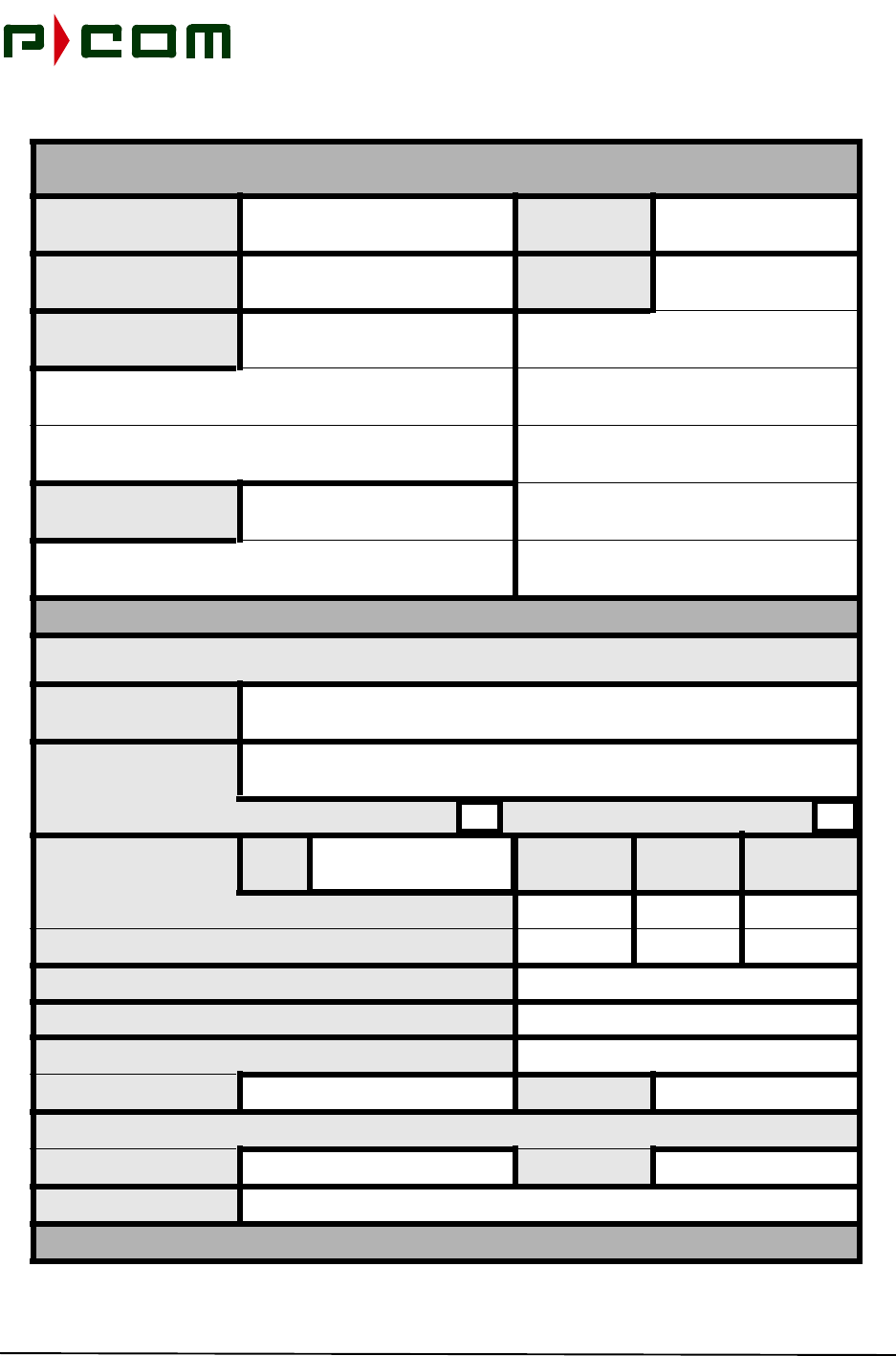
November 1999
B-2 M68333 Rev. A Tel-Link PMP - Sector Terminal Installation & Maintenance Manual
SITE SURVEY CHECKLIST
Engineer: Date:
Customer Address:
Contact Names:
Telephone Numbers:
SITE CHARACTERISTICS
Prior to site installation planning visit, complete line-of-sight, transmission engineering and preliminary frequency coordination work to
establish viability of path selected.
Site Name:
Site Designation:
Sector Terminal Remote Terminal
Coordinates: GPS
EPE Degrees Minutes Seconds
Latitude:
Longitude:
Ground Elevation AMSL (Above Mean Sea level)
Distance Between Hub and Remote Terminals (kilometers)
Azimuth (True) From Sector:
Hub/Sector: Remote:
Transmit Frequency (High/Low Band; Polarization)
Transit: Receive:
Available Conduit:
Page 1 of 6
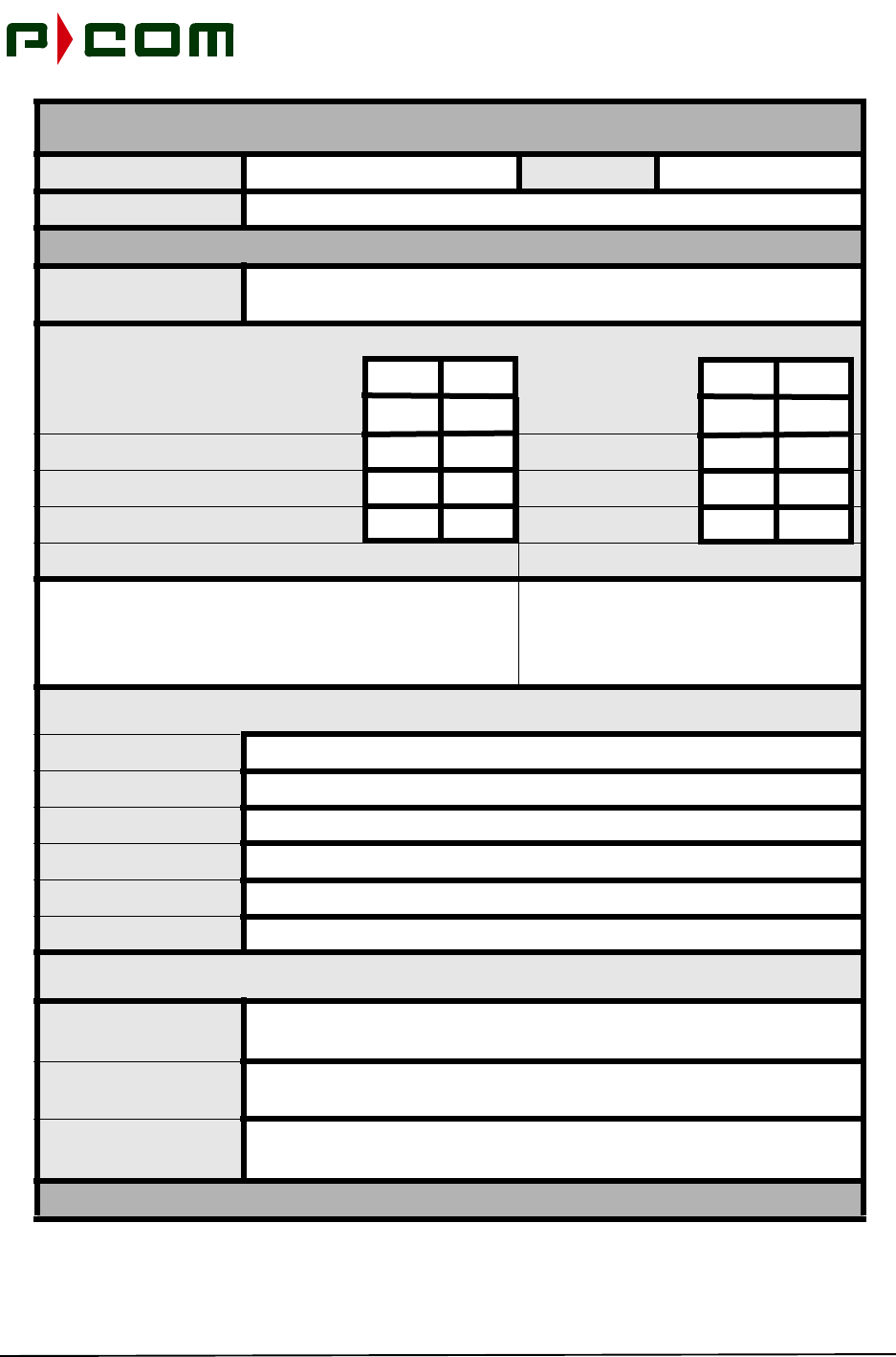
November 1999
M68333 Rev. A Tel-Link PMP - Sector Terminal Installation & Maintenance Manual B-3
Customer Date:
Site Name:
OUTDOOR EQUIPMENT
Roof Access
(Describe):
Site Access
Roof Access Door Ladder Req
Permit Req Access Keys Req
Roof Penetration Wall Penetration
Special Tools Req On-SIte Escort Req
If Yes, What Special Tools: If Yes, Who is Needed as the Escort:
Sketch/photos of Equipment and Site (on pages 5 and 6) - Include Site Layout (Topographical Map and Building Blueprints if available),
Location of Antenna/ODU, and briefly explain how the Antenna/ODU will be installed below:
Tripod:
Wall Mount
Parapet:
Tower:
Other:
Pole Diameter:
Show details in sketch of proposed mounting and hardware (pole) location. Show relationship to coaxial cable access and building
ground. Show lightning rod ground connect point if applicable.
Terrain
Considerations:
Obstructions:
Other Considerations:
Page 2 of 6
SITE SURVEY CHECKLIST
Yes No Yes No
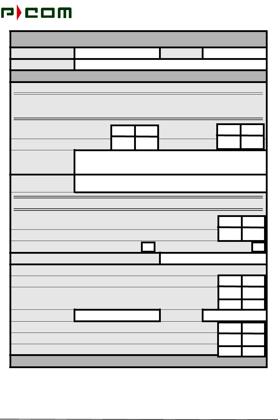
November 1999
B-4 M68333 Rev. A Tel-Link PMP - Sector Terminal Installation & Maintenance Manual
Customer Date:
Site Name:
INTERFACILITY POWER AVAILABILITY
Available Power (Voltage and Current
NOTE: Do not mount radio equipment in the proximity of machinery that can either generate
larege electromagnetic fields or large voltage spikes as they cycle On/Off (i.e. air
conditioners, elevator motores, etc.)
AC Power On Roof: AC Power At Rack:
Identify Location and
Distance to Available
AC Power:
Distance Between
ODU and IDU:
NOTE: Maximum distance of LMR-400 Cable is 1000 Feet.
Has Cable Been Ordered?
IFL Cable Supplied By: P-COM Customer
Distance Between IDU and Customer Premise:
Sketch/Photos Of Equipment - Cable Run from ODU to IDU
Show Access Points (i.e. Floors) (Sketch) (Space available on Pages 5 and 6)
IFL Exists in-place:
Is Plenum Rated Cable Required:
Length: Type:
Is Pull Rope Installed in Conduit
Is New Pull Rope Required:
Page 3 of 6
SITE SURVEY CHECKLIST
Yes No Yes No
Yes No
Yes No
Yes No
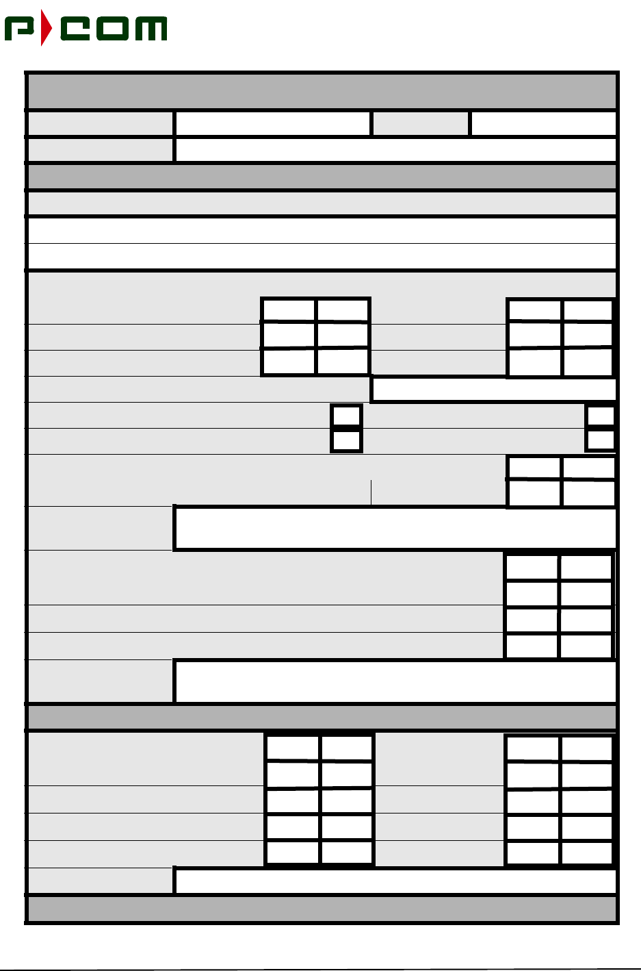
November 1999
M68333 Rev. A Tel-Link PMP - Sector Terminal Installation & Maintenance Manual B-5
Customer Date:
Site Name:
INDOOR EQUIPMENT
What Type of Terminating Equipment Will Be Used (Customer Premise Equipment)
Check Site For:
Phone Jack: AC/DC Power:
Fuse Panel: Battery Back-up
Number of IDUs Required:
IDU Mounting Rack Mounted Tabletop Mounted
Rack/Table Supplied By P-COM Customer
Rack or Table Ordered:
Limitations on Rack
or Table Floor Space:
Temperature/Humidity Controlled Room
Air Flow Restrictions:
Fans Needed:
Other Rack Installa-
tion Considerations:
TOOLS REQUIRED
Binoculars Camera
Cellular Phone (2 each) Compass
Flashlight/Strobe GPS Receiver:
Tape Measure
Other Equipment:
Page 4 of 6
SITE SURVEY CHECKLIST
Yes No Yes No
Yes No
Yes No
Yes No Yes No

November 1999
B-6 M68333 Rev. A Tel-Link PMP - Sector Terminal Installation & Maintenance Manual
Customer Date:
Site Name:
SKETCH OF EQUIPMENT AND SITE
Page 5 of 6
SITE SURVEY CHECKLIST

November 1999
M68333 Rev. A Tel-Link PMP - Sector Terminal Installation & Maintenance Manual B-7
Customer Date:
Site Name:
SKETCH OF EQUIPMENT AND SITE
Page 6 of 6
SITE SURVEY CHECKLIST

November 1999
B-8 M68333 Rev. A Tel-Link PMP - Sector Terminal Installation & Maintenance Manual

November 1999
M68333 Rev. A Tel-Link PMP - Sector Terminal Installation & Maintenance Manual Gloss-1
Glossary
NAME DESCRIPTION
AAL ATM Adaption Layer - A collection of standardized protocols providing
services to higher layers by adapting user traffic to a cell format.
AAU Antenna Alignment Unit
Active Window The window whose Title Bar is highlighted. Active windows lie in front
of all windows that intersect them in three dimensional space
AGC Automatic Gain Control
AIS Alarm Indicator Status - One of the Operations and Maintenance func-
tion types used for fault management.
AMI Alternate Mark Inversion - A type of bipolar line signaling used by DS-1
and DS-3 interfaces.
ANSI American National Standards Institute. A US technology standards
organization.
AMSL Above Mean Sea Level
ASIC Application Specific Integrated Circuit
ATM Asynchronous Transfer Mode - A broadband switching and multiplex-
ing, connection-oriented, high-performance and cost effective inte-
grated technology.
B8ZS Bipolar with Eight Zero Substitution - A line code substituting 8 zeros
with Bipolar Violations for bit synchronization purposes.
Base Station The center of a cell where Sector Terminal(s) are installed.
BER Bit Error Rate - A measure of the rate of bit errors in a digital system.
BNC Bayonet Nut Connector
BOD Bandwidth-On-Demand - A technique allocating more bandwidth to
users requiring it and reduces bandwidth to users that do not.
BPV Bipolar Violation - DS-1 and DS-3 line fault alarms.
BRI Basic Rate Interface - A ISDN service specification that provides two
64-Kbps B-channels and one 16-Kbps D-channel.
Calibration File A file used by the LSM to calibrate a particular model of ODU
CAS Channel Associated Signaling
CBR Constant Bit Rate - One of five service classes for the ATM layer. This
service type allows a user to define a specific cell delay, cell delay vari-
ation, and reserve a specific constant fixed bandwidth on the network.
CCITT Consultative Committee on International Telegraphy and Telephony.

November 1999
Gloss-2‘ M68333 Rev. A Tel-Link PMP - Sector Terminal Installation & Maintenance Manual
CCS Common Associated Signaling
CHAMP Connector
Chassis Number An integer value that uniquely identifies a chassis
Chassis Parameter A value that may be read and/or written from/to a board that exists
within a chassis. Examples of chassis parameters include
odu_Temperature for the ODU, or sc_Tx_Frequency in the Sector
Controller
Chassis Window The window that displays information about the individual boards mak-
ing up a chassis. The operator interacts with this window to control and
monitor chassis parameters.
CLAV Cell Available
Client Area The area of a window excluding the title bar and bounded by the win-
dow frame. The client area is used to display the document visually to
the operator.
Closing a Window Expanding a window down to its maximum size. Maximizing a window
under Windows 95 is performed by clicking on the maximize button on
the Title Bar
Configuration Files Files that contain the labels, desired values, sampling intervals, and
sampling active states for chassis parameters. These files are dis-
played graphically within Chassis Windows.
Configuration Section A section of a Configuration File containing parameters for a given
board that do not exist within any configuration tables.
Configuration Table A table of parameters lying within a configuration section,
Continuous Get The process of automatically performing Gets on chassis parameters
at selected intervals
CPE Customer Premise Equipment - Customer provided equipment that
connects to the interface port(s) of the IDU.
CRC Cyclic Redundancy Check - A process used to check the integrity of a
block of data.
Current Value The current setting of a chassis parameter. Used in conjunction with a
Get operation
DBPSK Differential Bi-Phase Shift Keyed
Debug Port The serial port used by the LSM to monitor and debug a PMP System.
Definition Files Files that contain the VID number, PID number, sample rate and sam-
pling active settings, as well as enumerated values for chassis param-
eters. These files are displayed graphically with Chassis Windows
NAME DESCRIPTION

November 1999
M68333 Rev. A Tel-Link PMP - Sector Terminal Installation & Maintenance Manual Gloss-3
Desired Value The value that the operator wishes to change a chassis parameter to.
Used in conjunction with a Set operation
Desired Value The value one wishes to change a chassis parameter to. Used in con-
junction with a Set operation.
Desktop The backdrop against which applications run in the Windows 95 envi-
ronment. It is in reality the parent window of all windows present with
Windows 95.
Detailed Help Detailed information about an object, available by clicking on the
arrow/question mark button in the Toolbar and then clicking on the
object.
DFM Drive Fault Monitor
Dialog Box A window consisting of controls with which an operator interacts. Dia-
log boxes come in two flavors: modal dialog boxes, which require that
the operator terminate the dialog box before other window objects
present in the application may be accessed, and modeless dialog
boxes, which allow the operator to interact with other window objects at
any time while the dialog box exists.
DLL Dynamic Link Library - Libraries of code shared by applications
DLL Libraries Libraries of code shared by applications
Down Link The RF communications path from a Base Station to the Remote Ter-
minal
DQPSK Differential Quandrature-Phase Shift Keyed
DSP Digital Signal Processor
DSX DS-n customer premise equipment
EIA Electronics Industry Association
EIRP Effective Isotropic Radiated Power
EMC Electromagnetically Coupled
EPLD Electronically Programmable Logic Device
Error Code An integer value indicating success/failure at performing a Set/Get
operation.
Error Message A message received from the PMP System via the LSM Port that gives
information on an error that was detected within the PMP System.
Error messages may be displayed via the Error Message Window.
ESF Extended Super Frame Format - Combination of 24 T1 frames.
ETSI European Telecommunications Standards Institute - European equiva-
lent of ANSI.
NAME DESCRIPTION

November 1999
Gloss-4‘ M68333 Rev. A Tel-Link PMP - Sector Terminal Installation & Maintenance Manual
Explorer Short for Windows 95 Explorer, the application that comes bundled
with Windows 95 allowing the manipulation of drives, directories and
files.
EXZ Excessive Zero Events - Used by DS-3 interface.
FCC Federal Communications Commission - A US regulatory commission.
FDDI Fiber Distributed Data Interface - ANSI standard for implementing high-
speed (100-Mbps) LAN over fiber.
FDMA Frequency Decision Multiple Access - A technique that allows multiple
users access to bandwidth by subdividing into multiple channels.
FEC Forward Error Correction - An error correction technique allowing the
receiver to correct some errors in the received signal.
FERF Fare End Receive Failure
FPGA Field Programmable Gate Array
FSK Field Shift Keyed
FWA Fixed Wireless Access
Get Operation The process of obtaining the current value of a chassis parameter
GUI Graphical User Interface
HDB3 High Density Bipolar Order 3
HDLC High-level Data Link Control - A synchronous bit-oriented protocol for
serial data.
Hex Records Records collectively making up a hex .rec file, the file format used for
software updates. Motorola defines the standard for the records used
by the LSM for software updates.
IDU Indoor Unit - PMP chassis, including cards populating the chassis,
located inside a building.
IF Intermediate Frequency
IFL Interfacility Link - A communications link between the IDU and ODU
Incoming Packets Packets of data received by the Local Site Manager via a serial port
ISDN Integrated Services Digital Network - Digital service for voice, data,
and video.
ISP Internet Service Provider
Keyboard Accelerator A keystroke sequence that emulates the selection of a menu item
Keystroke Sequence A group of keys on the keyboard simultaneously depressed
NAME DESCRIPTION

November 1999
M68333 Rev. A Tel-Link PMP - Sector Terminal Installation & Maintenance Manual Gloss-5
Label A name uniquely identifying a chassis parameter
LAN Local Area Network
LCD Liquid Crystal Display
LED Light Emitting Diode
LIU Line Interface unit
LMCS Local Multi-Point Communications Services
LMDS Local Multi-Point Distribution System
LNA Low Noise Amplifier
Logs Status information reports accumulated over time. Examples include
incoming packets logs, or error message logs.
LOS Loss of Signal
LSM Local Site Manager -Laptop or desktop PC based software tool used to
monitor, control and configure the PMP System.
LSM Installer The software application that installs the LSM and all subordinate files
LSM Port The serial port used by the LSM to communicate with a PMP System
LSM Uninstaller The software application that uninstalls the LSM and all subordinate
files
Main Window The window that contains the menu bar and toolbar, serving as the
parent of all windows and dialog boxes. Closing the Main Window ter-
minates the LSM
Maximizing a Window Expanding a window to its maximum size. Maximizing a window under
Windows 95 is performed by clicking on the maximize button in the title
bar.
MC Modem Controller
MCF Motorola Cold-Fire Processor
Menu Bar A list of individual menus. Present at the top of the Main Window
Menu Item An individual item that resides within a menu which may be selected by
the operator
MIB Management Information Base - Database containing information
regarding network management and performance.
Minimizing a Window Shrinking a window down to a single title bar. Minimizing a window
under Windows 95 is performed by clicking on the minimize button on
the Title Bar
Mouse Cursor The cursor that displays the current position of the mouse
NAME DESCRIPTION

November 1999
Gloss-6‘ M68333 Rev. A Tel-Link PMP - Sector Terminal Installation & Maintenance Manual
NCO Numerical Control Oscillator
NMA Network Management Agent
NMS Network Management System
NOC Network Operations Center
ODU Outdoor Unit - PMP communications equipment located outside a
building connected to an antenna.
OMT Othogonal Mode Transducer
Operator The person who is interacting with the Local Site Manager
OTA Over the Air
Outgoing Packets Packets of data transmitted via the LSM Port to the PMP System.
PA Power Amplifier
PCB Printed Circuit Board
PD Pattern Detect
PID Process ID - A number uniquely identifying a process with a board.
PMP Point-to-Multipoint
PMP System The combination of hardware and embedded software that make up
the P-COM Point-to-Multipoint System
Popup Menu A menu that comes into existence when a Windows Object is selected
by the operator while the right mouse button is pressed. Popup Menus
serve as a convenient means of querying/changing the settings for a
given Window Object
POST Power Up Self Test
PSN Public Switched Network
PTN Public Telephone Network
QAM Quadrature Amplitude Modulation - A high bandwidth efficiency modu-
lation technique
QPSK Quadrature Phase Shift Keyed - Digital modulation technique.
Quick Help A brief summary of a chassis parameter, available by double clicking
on the chassis parameter in the label column of a Chassis Window.
RAC Remote ATM Controller - ATM controller card used in the Remote Ter-
minal IDU to manage and control the traffic a the Remote site.
RAM Random Access Memory
RCS Redundancy Control Switch
NAME DESCRIPTION

November 1999
M68333 Rev. A Tel-Link PMP - Sector Terminal Installation & Maintenance Manual Gloss-7
Remote IDU Remote Terminal Indoor Unit chassis located at the remote location
Remote ODU Remote Terminal Outdoor Unit located at the remote location, con-
nected to a directional antenna pointed towards the Sector Terminal.
Remote Terminal Consists of a Remote IDU, Remote ODU and Interfacility Link
Restoring a Window Resizing a window to its previous size. Restoring a window under Win-
dows 95 is performed by clicking on the restore button in the title bar.
RF Radio Frequency
RMA Return Material Authorization
ROM Read Only Memory
RSSI Receive Signal Strength Indicator
RU Rack Unit
Rx Receive Signal
SAC Sector ATM Controller - ATM controller card used at the Base Station/
Sector Terminal IDU to manage and control the traffic at the sector.
Sample Interval The rate at a Continuous Get is performed on a chassis parameter
Sampling Active Whether or not Continuous Gets will be performed on a chassis param-
eter
SAW Surface Acoustic Wave
SCC Serial Communication Controller
Scroll Bars Bars present at the bottom and/or right edge of a Window enabling the
operator to scroll the data upwards or downwards, thus observing
information that lies beyond that capable of being displayed in the win-
dow
SDH Synchronous Digital Hierarchy - A hierarchy for very high-speed digital
transmissions over optical fiber links
Sector A geographic area radiating out from a Base Station. Typically referred
to as the area covered by a Sector Antenna
Sector IDU Sector Terminal Indoor Unit chassis located at the Base Station
Sector ODU Sector Terminal Outdoor Unit chassis located at the Base Station loca-
tion, connected to an antenna providing coverage over a sector.
Sector Terminal Consists of one or more Sector IDUs connected to a common, or
redundant, set of Hub IF Combiners and Sector ODU/Antenna assem-
blies
NAME DESCRIPTION

November 1999
Gloss-8‘ M68333 Rev. A Tel-Link PMP - Sector Terminal Installation & Maintenance Manual
Selection Highlighting an item for an action via the process of single clicking on
the item. Holding down the Shift Key while selecting items allows con-
tiguous selections. Holding down the Ctrl Key while selecting items
allows noncontagious selections.
Set Operation The process of changing the current value of a chassis parameter
Settings Options for customizing the Local Site Manager to an operator's prefer-
ences. Available from the Setup Dialog Box
SF Super Frame Format
Shortcut A Windows 95 Object that points to an application or data file. Double
clicking on a shortcut to an application executes the application. Dou-
ble clicking on a data file executes the application tied to the data file
Site Diagnostic Report A report produced listing detailed information about the current status
of all chassis making up the system
Slot Number A value that uniquely identifies a board within a chassis
SNMP Simple Network Management Protocol - Protocol for exchanging net-
work management information.
SNR Signal-to-Noise Ration - A measurement of the strength of the RF sig-
nal when compared to the background noise level.
Software Updating The process of updating code for a board that resides within a chassis
Splitter Bar A vertical bar separating panes of a window. The splitter bar may be
dragged to resize the panes of a window.
Start Menu A menu containing applications (or shortcuts to applications) that are to
be executed whenever Windows 95 boots
Status Bar An area which enables the displaying of detailed information about the
current menu item that is selected, or about the current status of an
operation. Present at the bottom of the Main Window
STM Synchronous Transfer Mode
STP Shielded Twisted Pair
STS Synchronous Transport Signal
System Menu The menu accessible by clicking on the icon that resides at the far left
corner of the title bar of a window. The System Menu contains a list of
operations commonly performed on windows.
TAC Technical Assistance Center
Task Bar The bar that runs along the bottom of the Windows 95 User Interface
TDM Time Division Multiplex
NAME DESCRIPTION

November 1999
M68333 Rev. A Tel-Link PMP - Sector Terminal Installation & Maintenance Manual Gloss-9
TDMA Time Division Multiple Access - A technique allowing multiple users
access to a single channel through time sharing.
Title Bar The bar that runs along the top of Windows. The title bar contains the
name of the document (or some means of identifying its purpose), as
well as the close box, minimize box, and maximize box.
Toolbar A list of buttons serving as an equivalent to the selection of menu items
that reside within the Menu Bar. Present immediately below the Menu
Bar of the Main Window
Tooltip A small popup window appearing whenever the mouse cursor hovers
over an object for a given amount of time. Tooltips are most often used
to supply concise help for Toolbar buttons.
Tx Transmit Signal
UNI User Network Interface - Interface between the Remote Terminal and
the ATM network. The ATM forum has defined two contexts in which
the UNI appears: Public UNI, connecting ATM equipment within a pri-
vate network, either hosting or switching with public network provider
networks. Private UNI, used exclusively to connect hosts to switches
where both are managed by the same administrative entity.
Uplink The RF Communications path from the Remote Terminals to the Base
Station
VID Variable ID - A number uniquely identifying a parameter.
VOM Volt-Ohm-Meter
Whitespace Tabs or spaces. This term originates from the Unix world
Windows Object An object presented to the operator through the Windows 95 user
Interface. Window objects encompass such thins as icons, menus, and
windows
WLL Wireless Local Loop
VBR-nt Variable Bit Rate-non real time - One of five service classes for the
ATM layer.
NAME DESCRIPTION

November 1999
Gloss-10‘ M68333 Rev. A Tel-Link PMP - Sector Terminal Installation & Maintenance Manual
This Page Intentionally Left Blank

November 1999
M68333 Rev. A Tel-Link PMP - Sector Terminal Installation & Maintenance Manual
Reader Comment Form
We welcome your comments and suggestions for improving our manuals. Please record your suggestions
below and FAX the completed form with your comments to (407) 674-3797.
NOTE: This form is for documentation comments only. Problems with hardware or software
should be reported separately to the Technical Assistance Center at 1-(877)-674-3600.
3. Did you find any omissions or inaccuracies in the manual? If so, please specify the page and the prob-
lem. (It may help to include a marked up copy of the page along with this form.)
____________________________________________________________________________________
____________________________________________________________________________________
4. Did you find this manual understandable, usable, and well organized? Please make suggestions for
improvement.
____________________________________________________________________________________
____________________________________________________________________________________
5. Is there sufficient documentation on the associated hardware or software required for your use of the
Point to Multipoint System, as described in this manual? If not, specify the type of information you feel
is missing.
____________________________________________________________________________________
____________________________________________________________________________________
6. Please indicate the type of user/reader that you most nearly represent:
_____System programmer/System Manager _____Maintenance Technician
_____Process Engineer _____Other_______________________
7. Please indicate the way(s) in which you use this manual:
_____Instructional Tool _____Other_______________________
_____Reference Tool
Name _________________________________ Title __________________________________
Company______________________________ Division_______________________________
Address_______________________________ City __________________________________
Telephone_____________________________ State, Zip/Country ______________________
Date__________________________________