P Com PMP-01-280 User Manual Cover

P Com Inc Cover

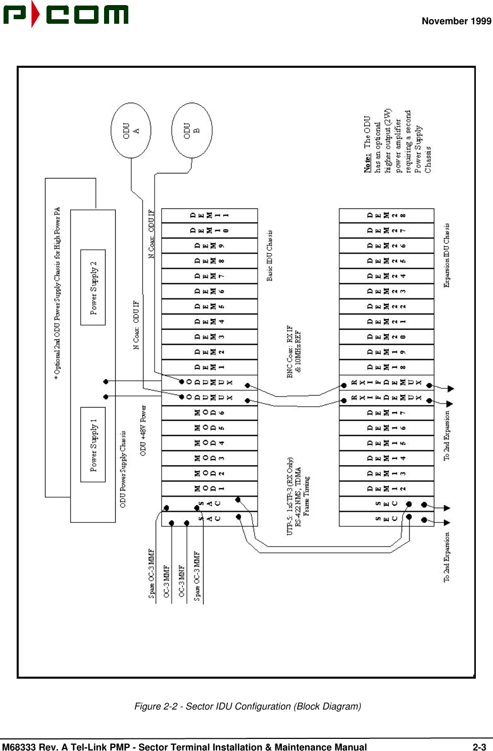
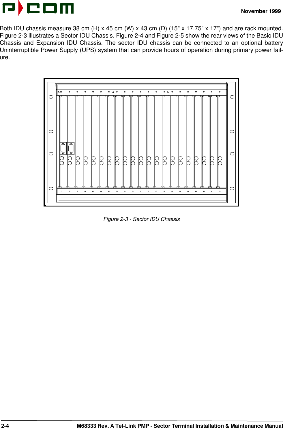
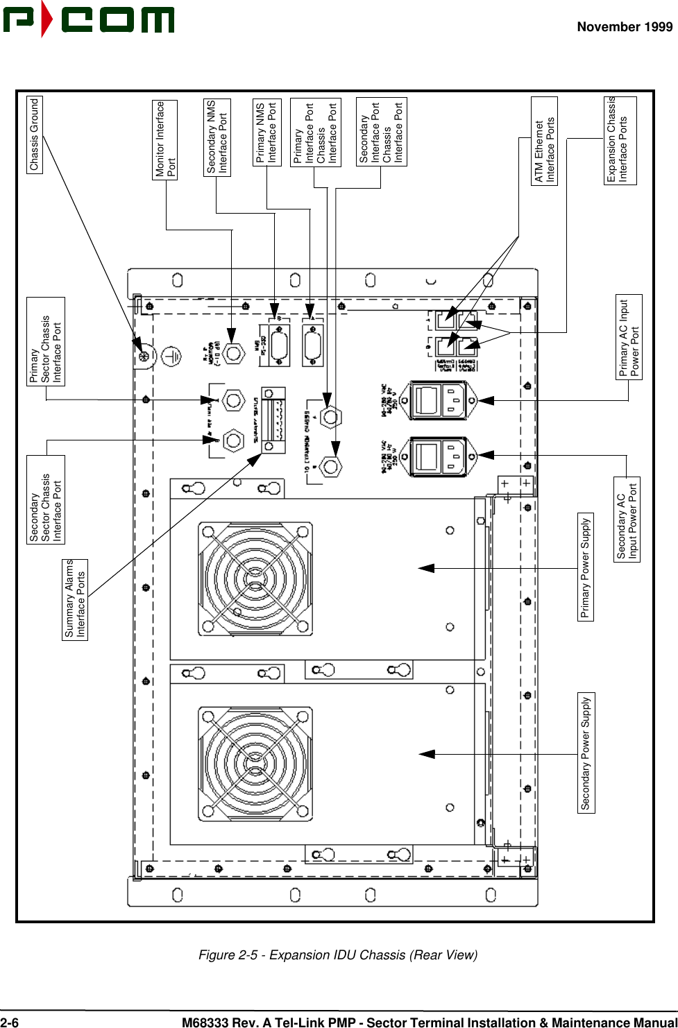
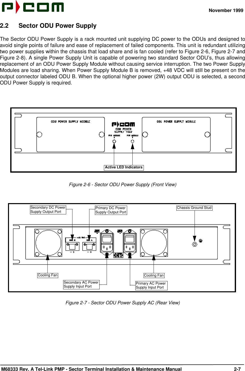
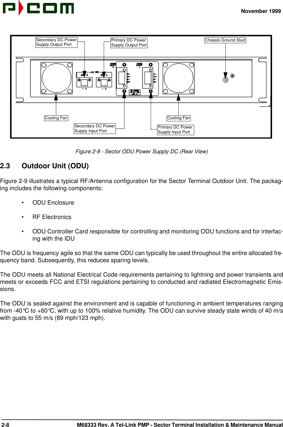
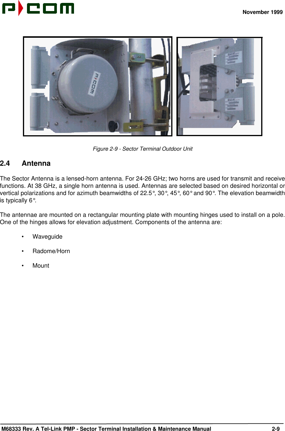
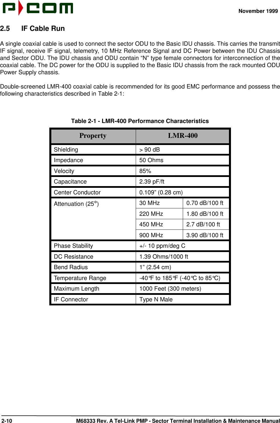
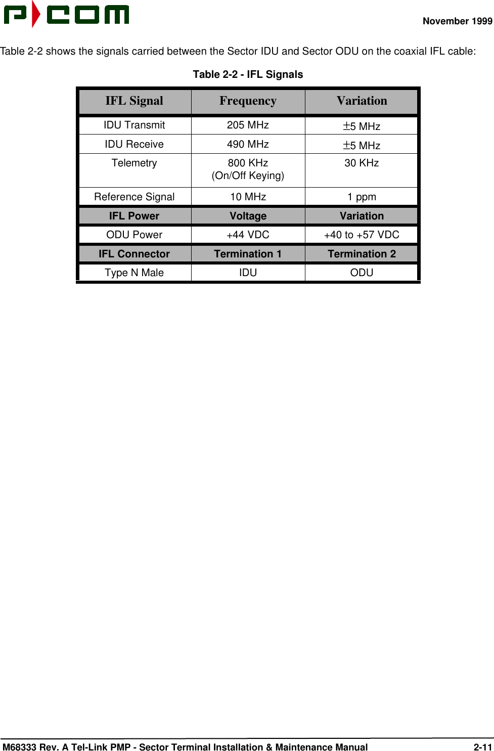
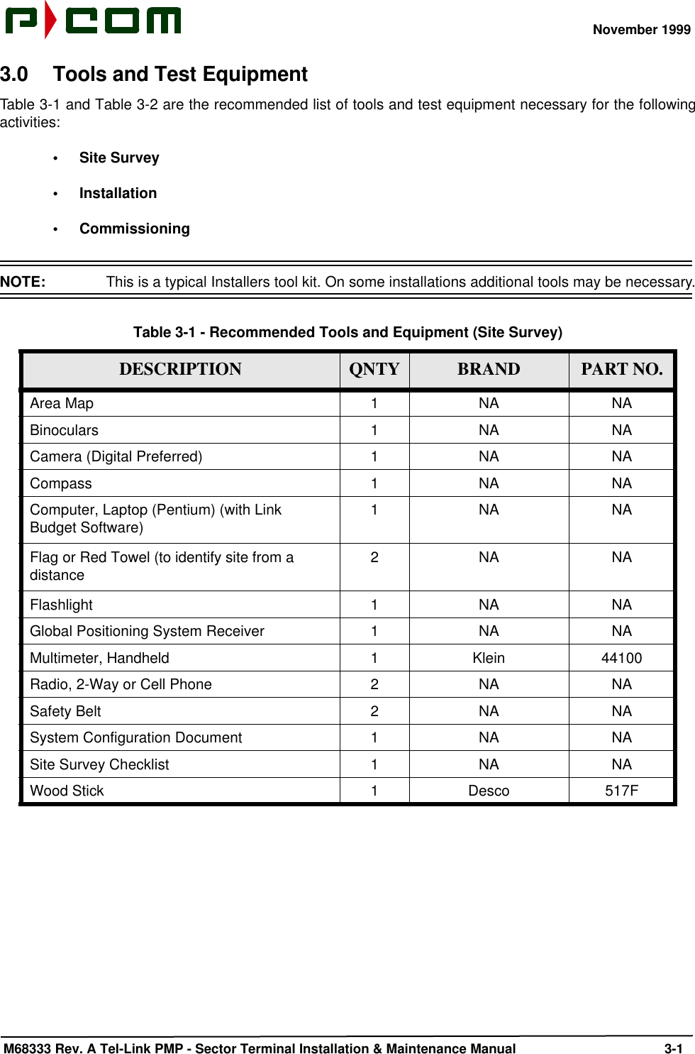
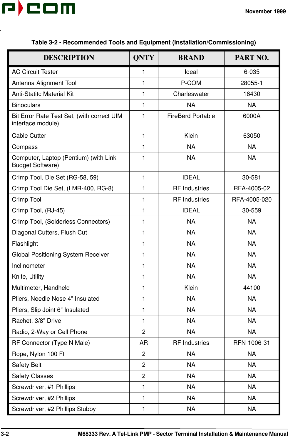
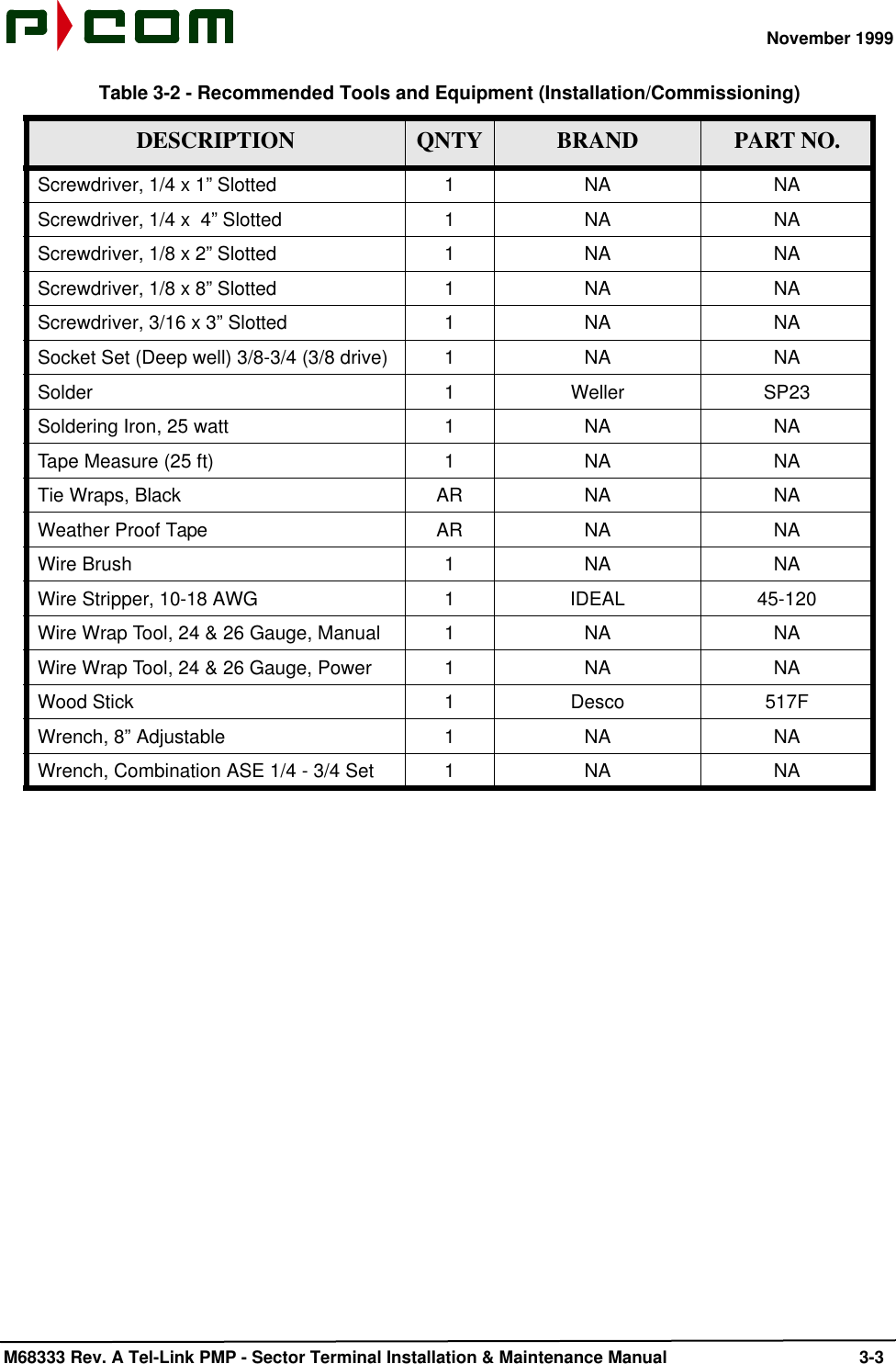
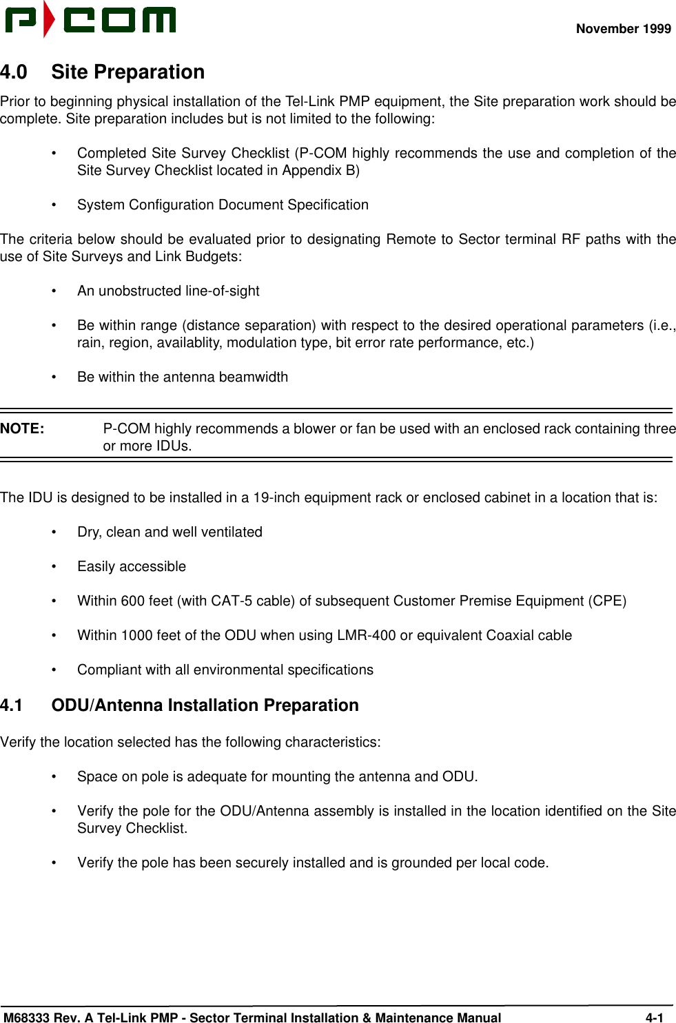
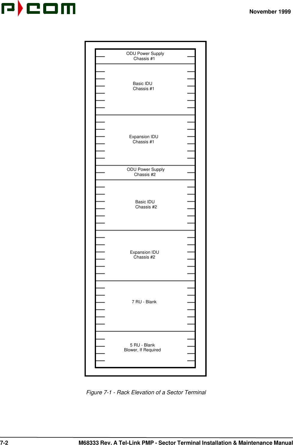
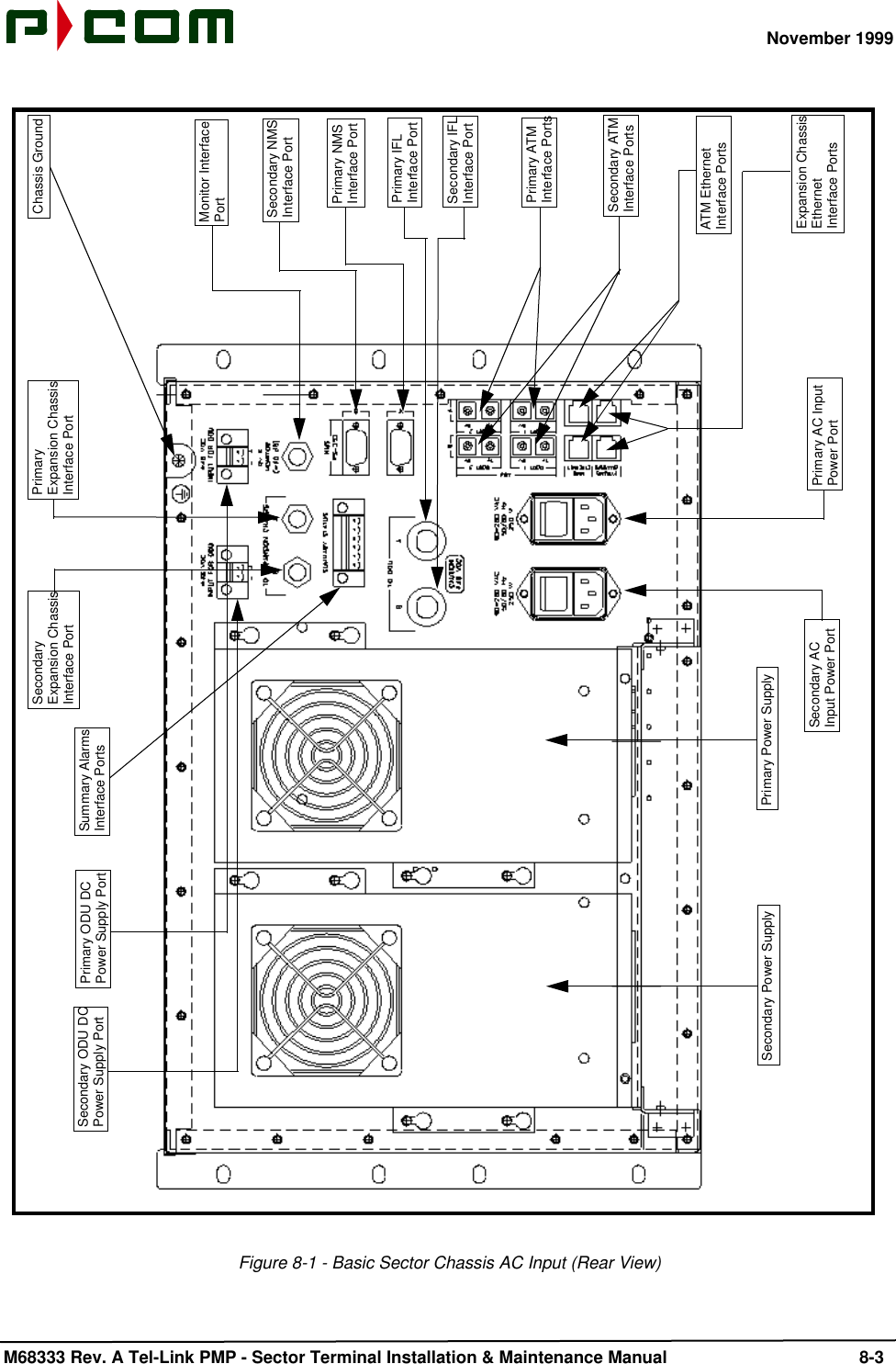
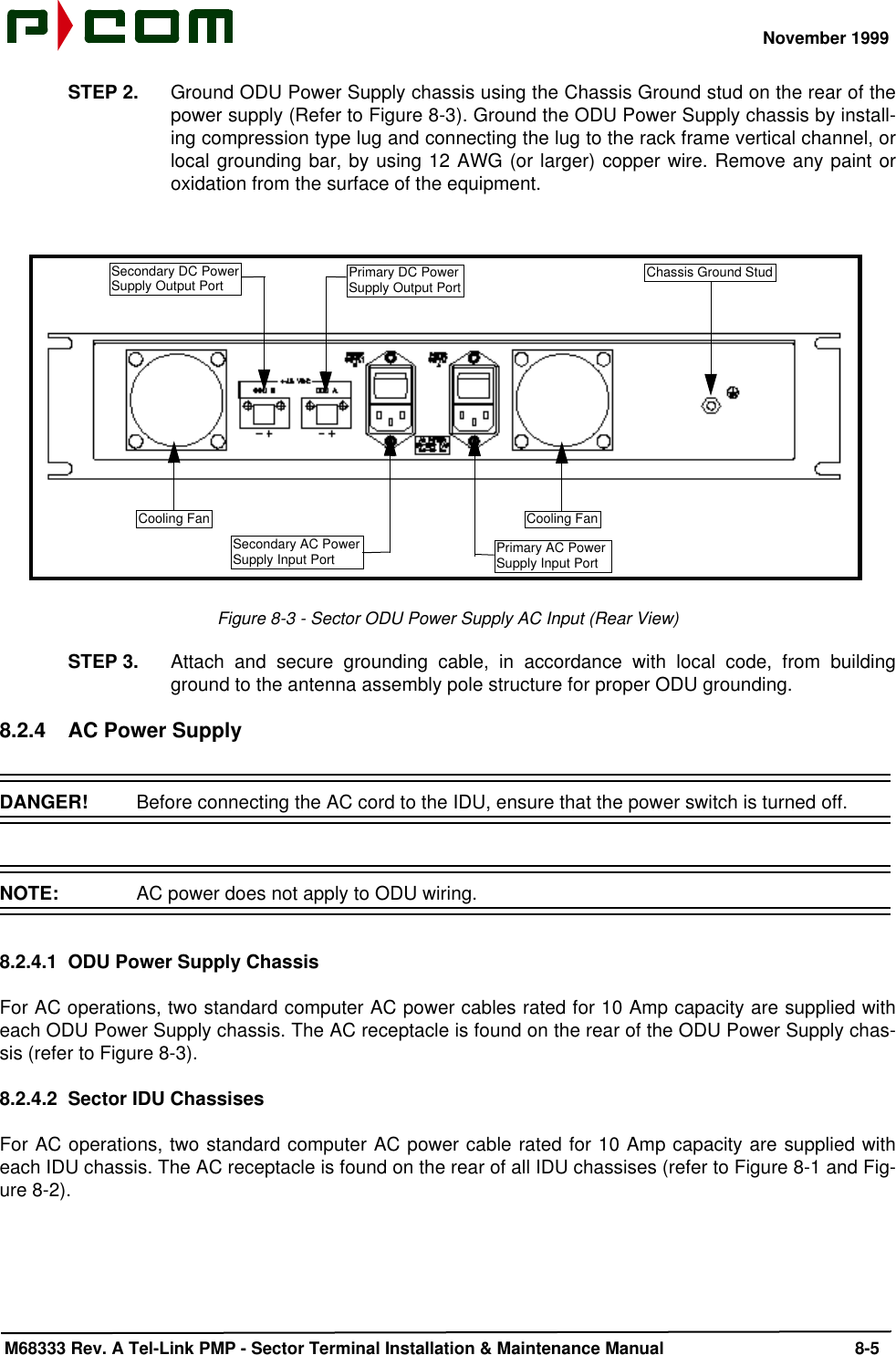
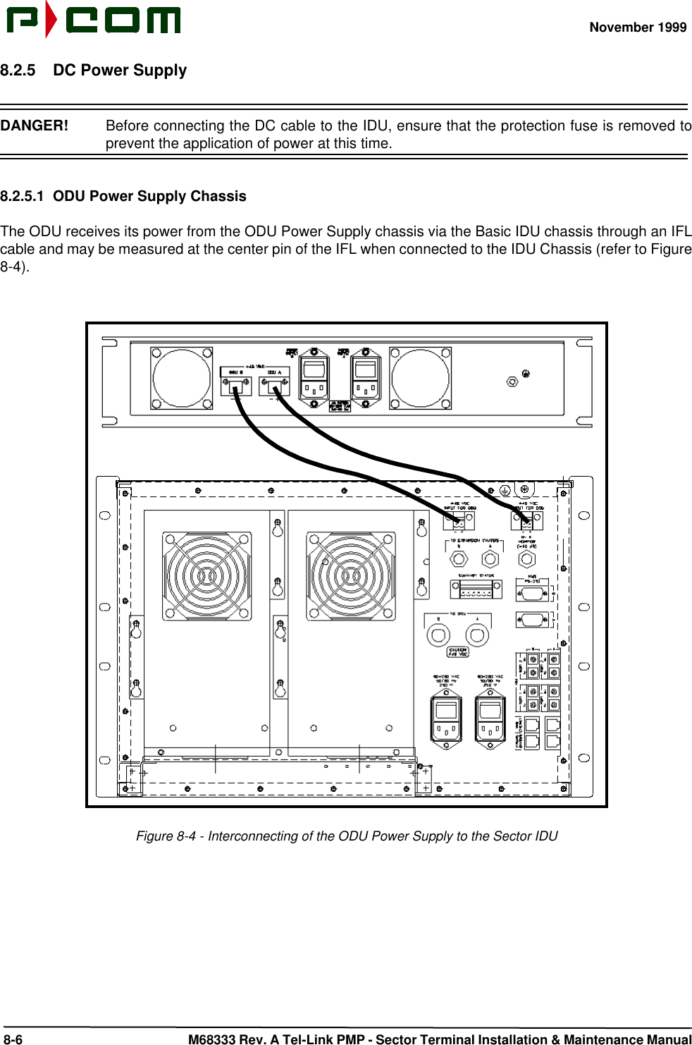
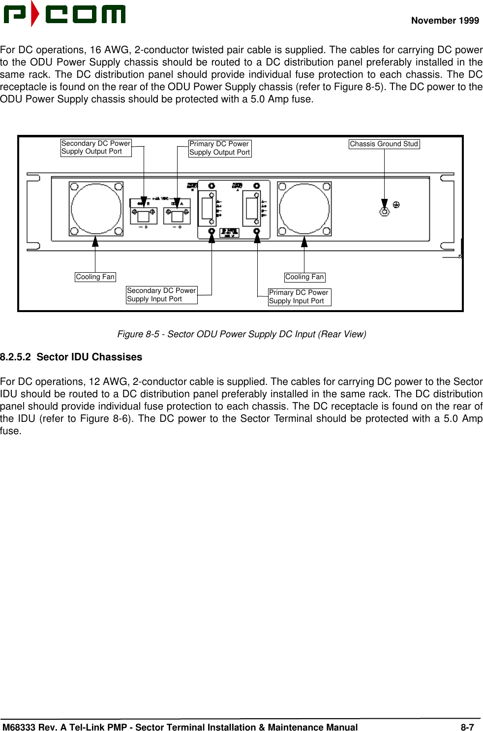
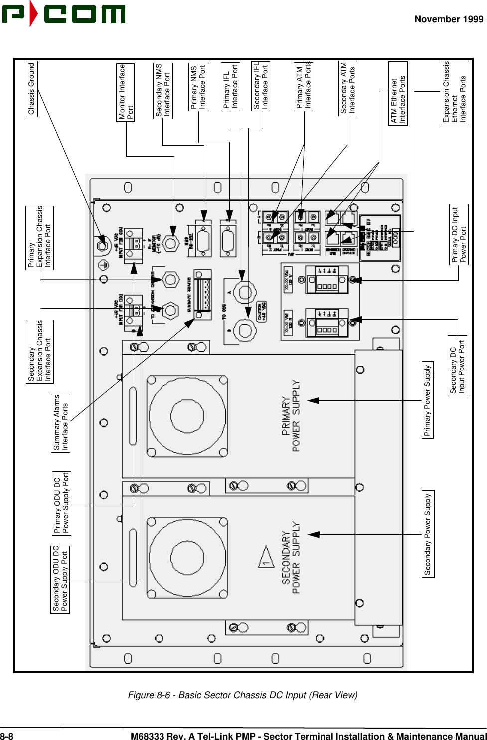
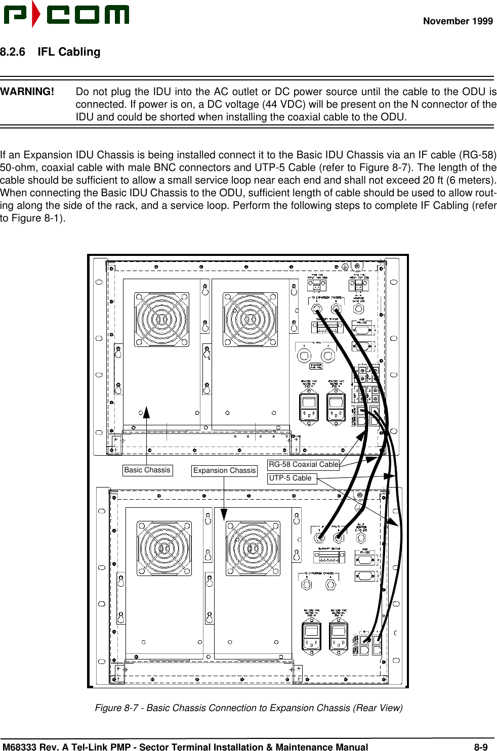
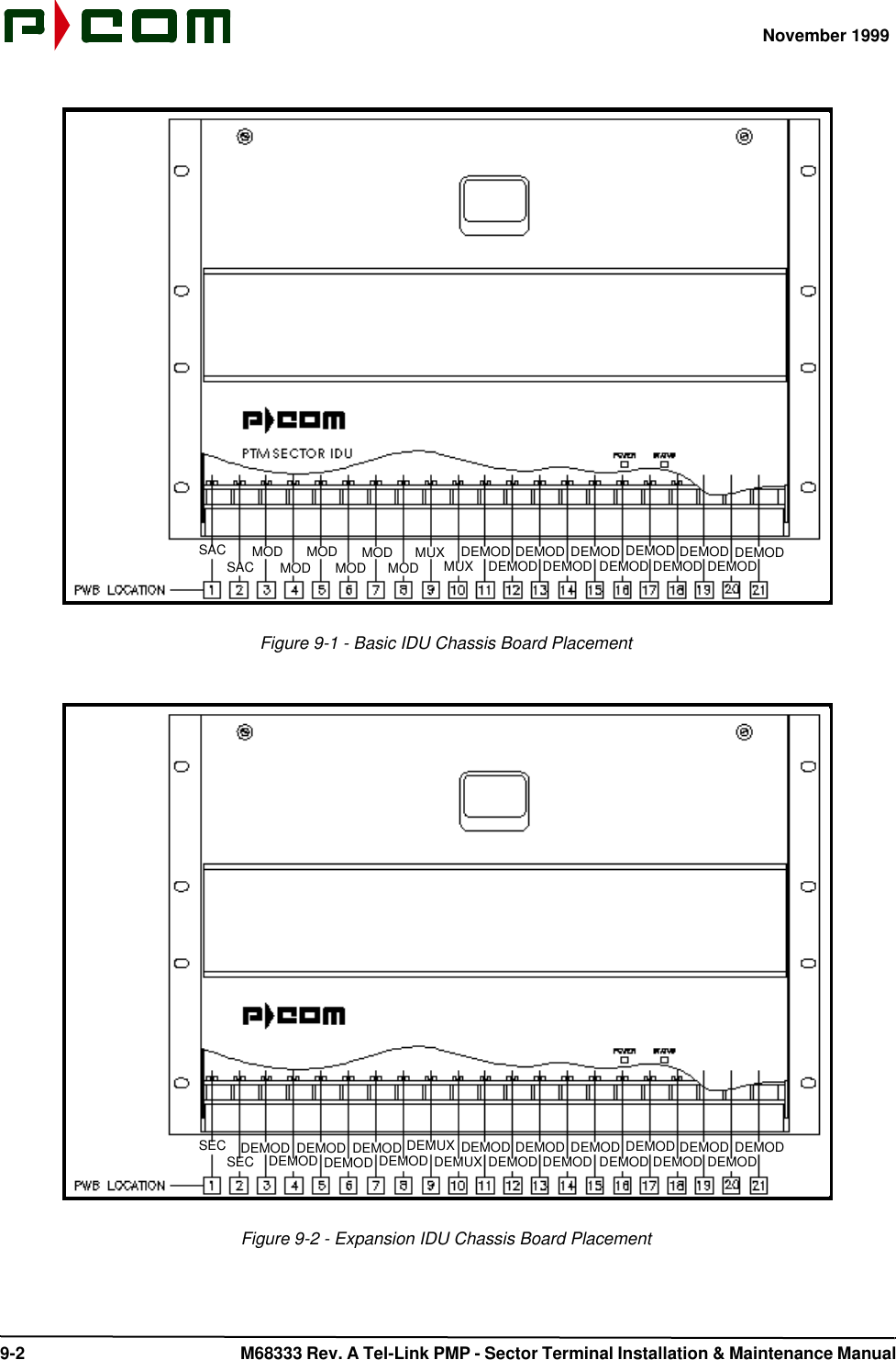
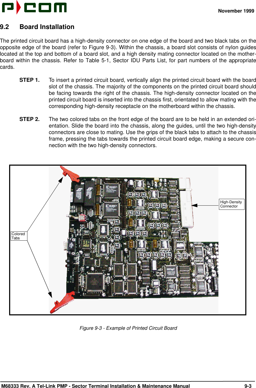
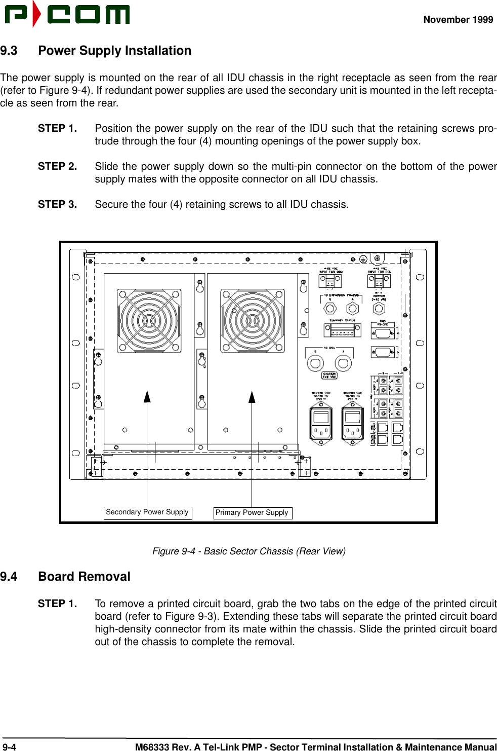
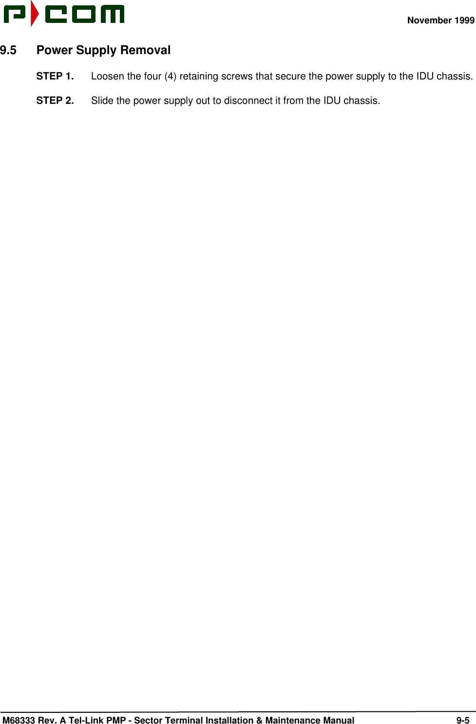
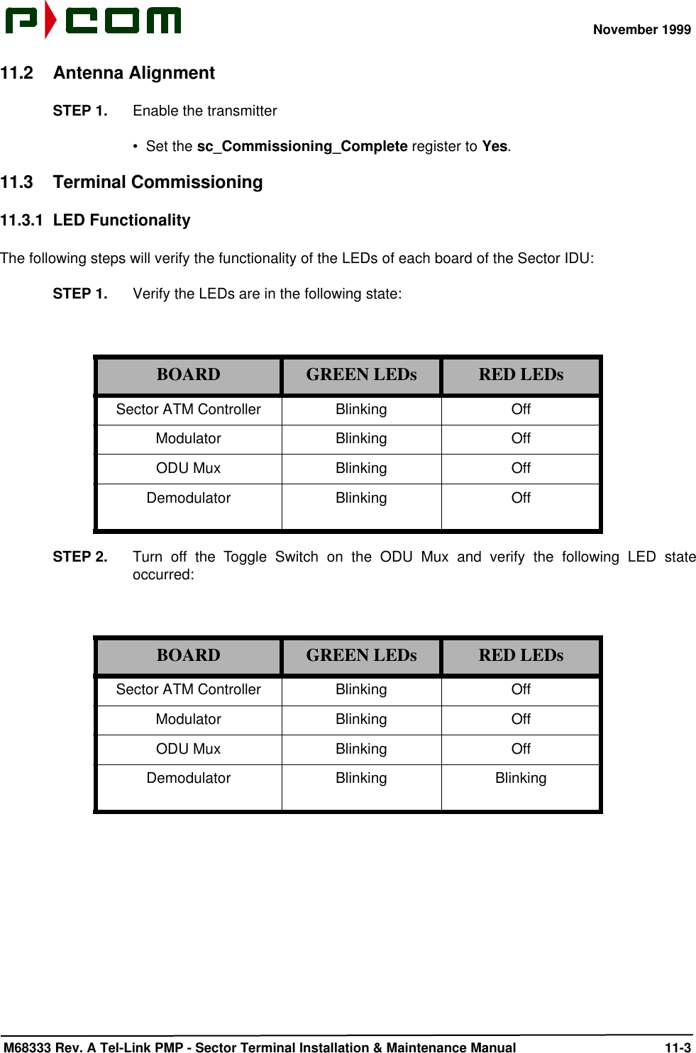
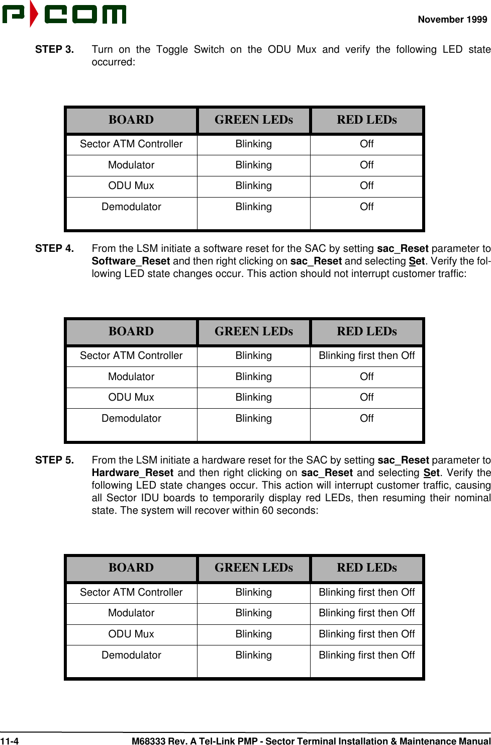
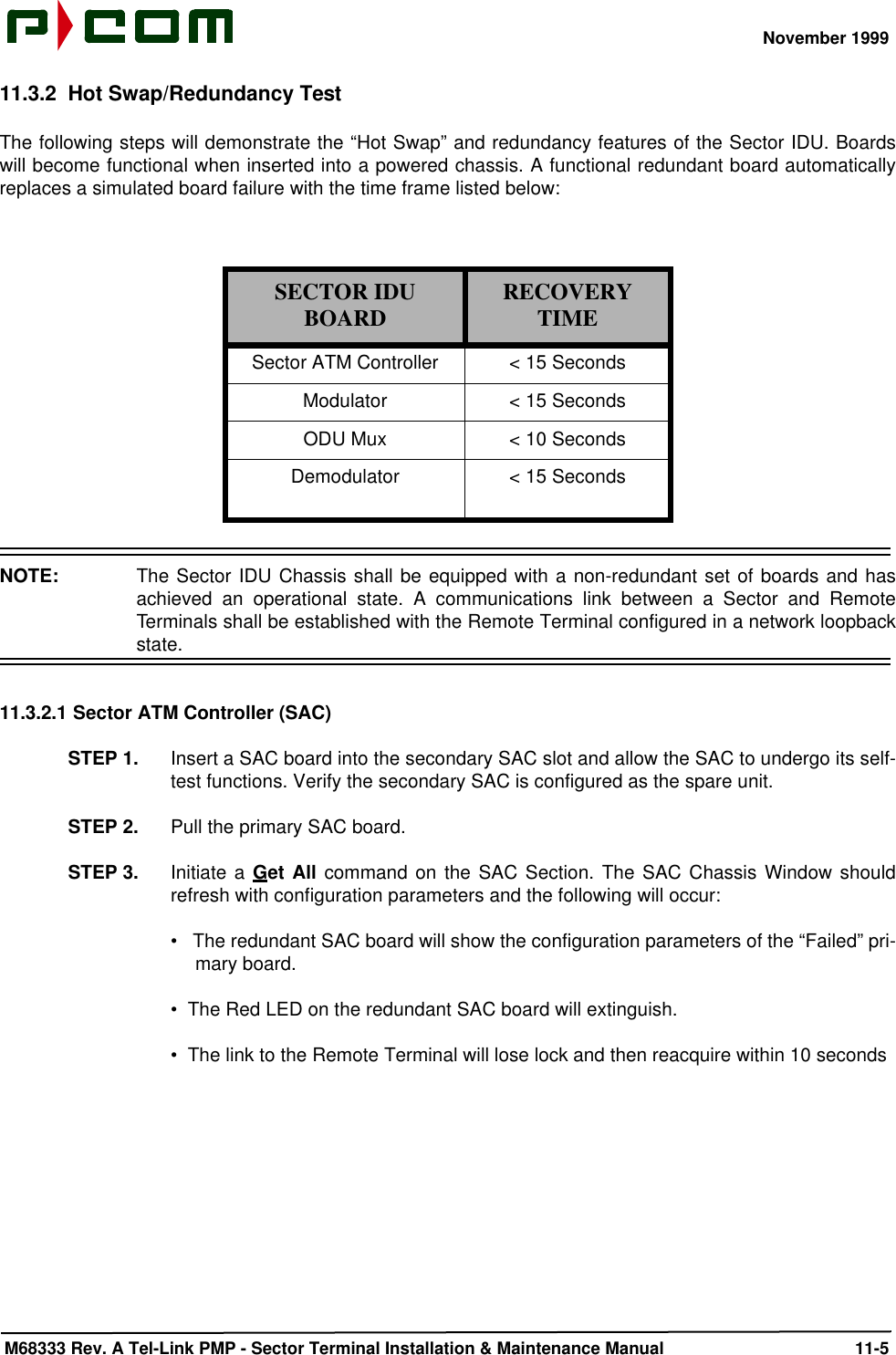
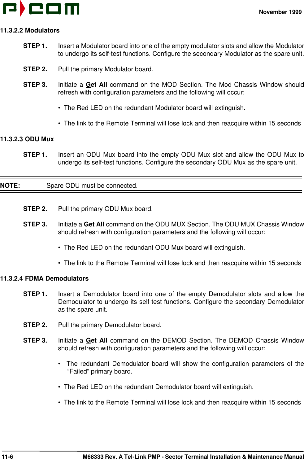
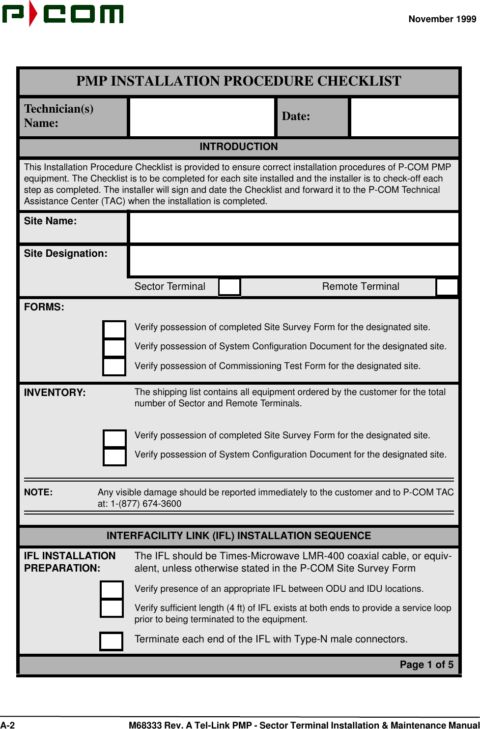
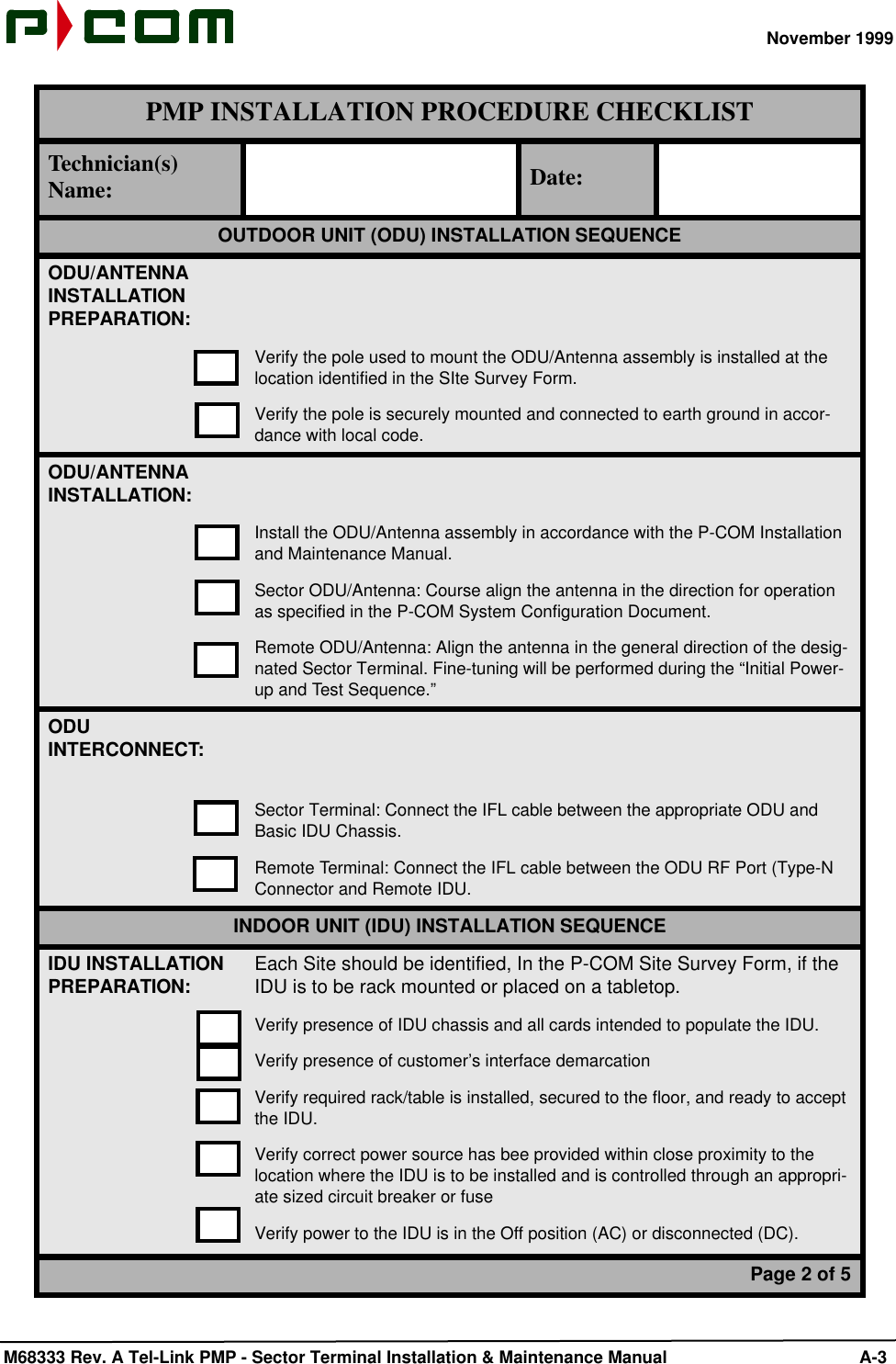
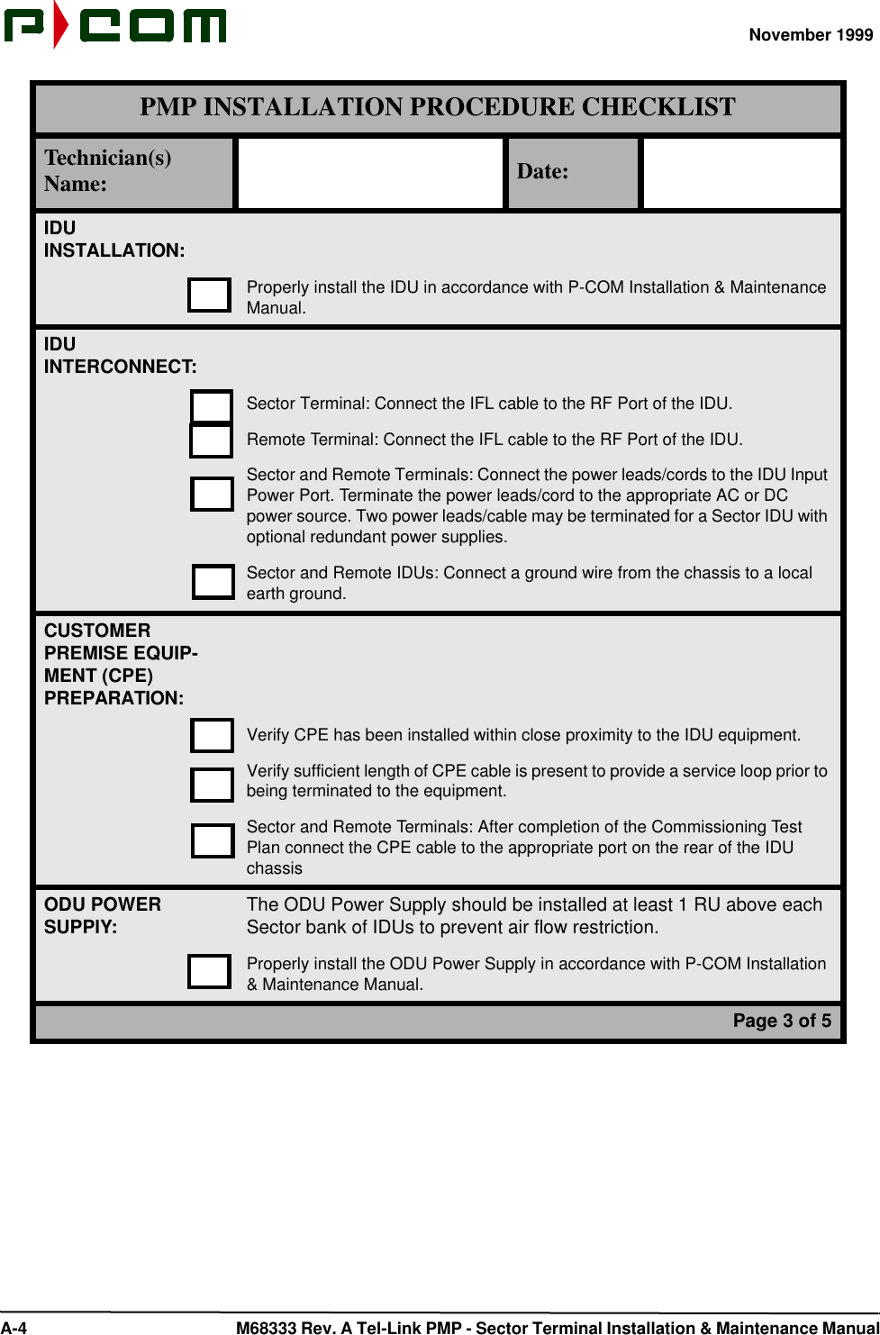
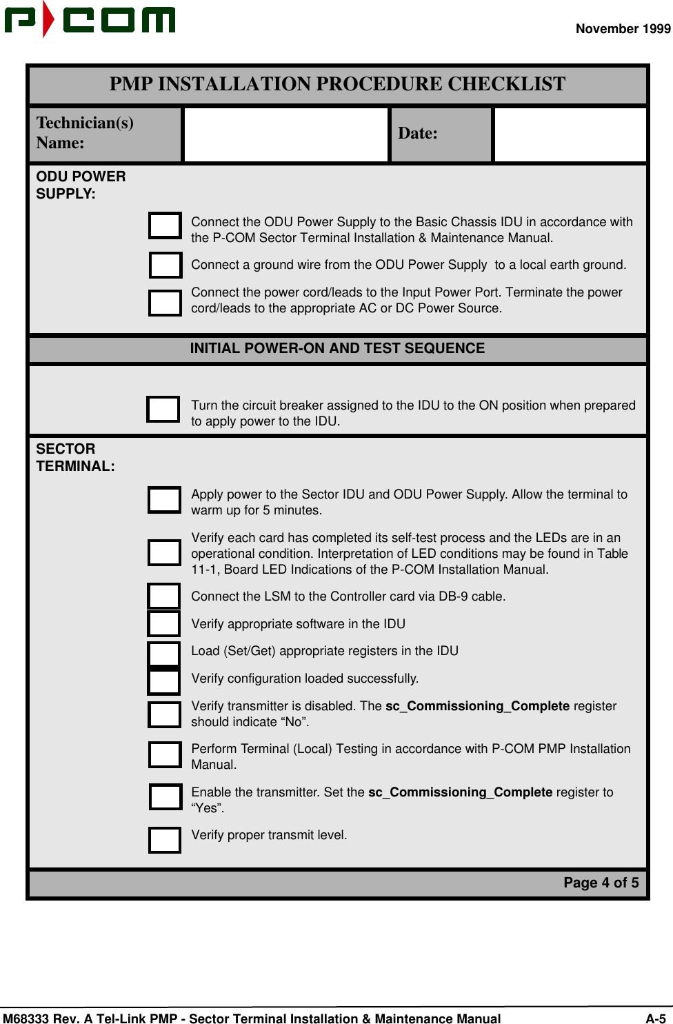
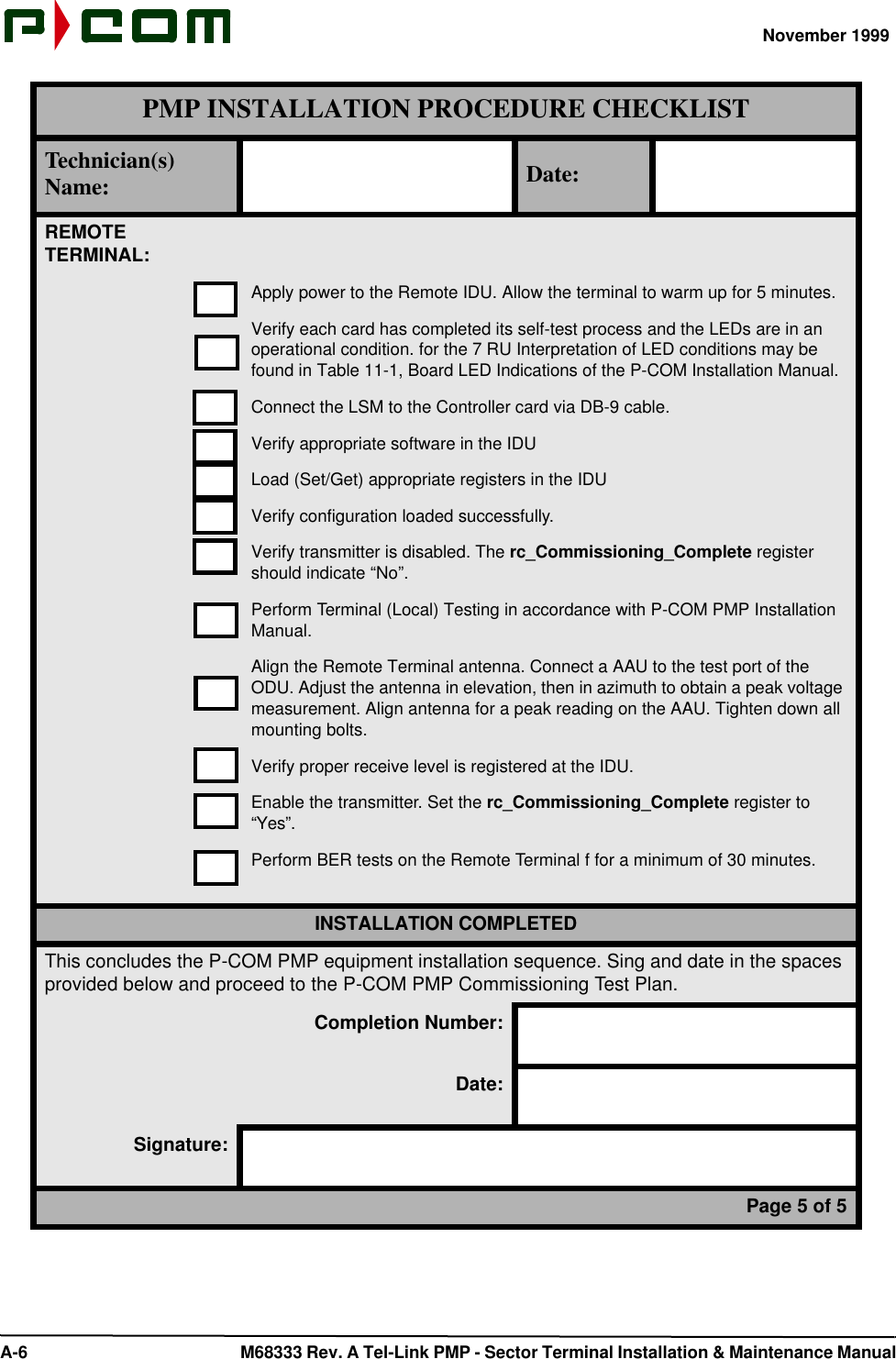
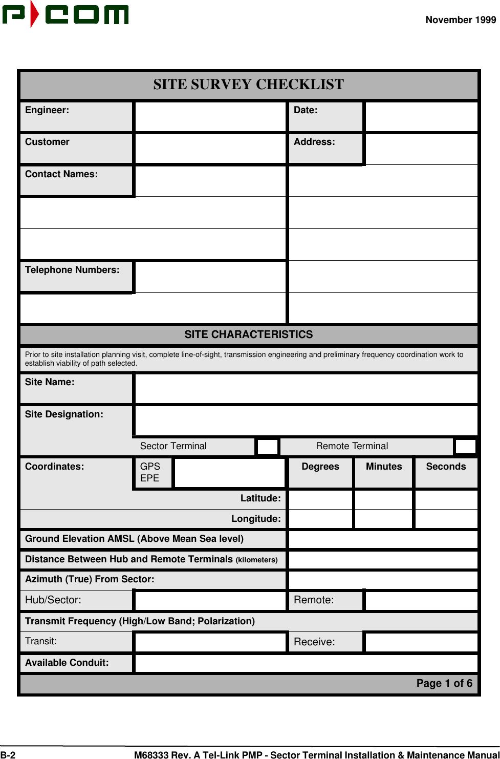
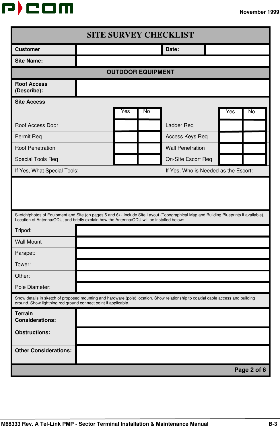
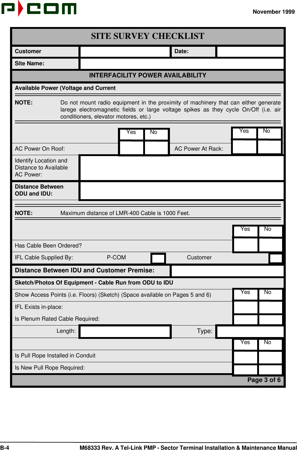
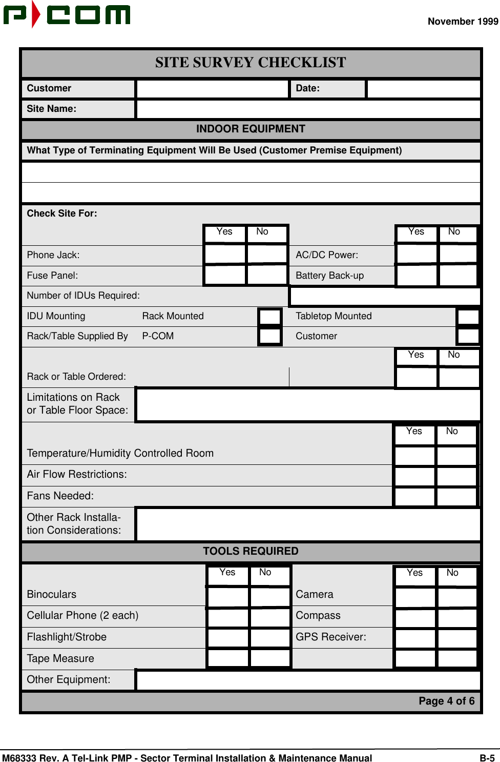
Exhibit S Product Installation and Operation Manual

November 1999  No. M68333 Rev. AIssued by P-COM, Inc.1801 Penn Street, Melbourne, Florida 32901 Printed in U.S.AEvery effort has been made to ensure that the information contained herein is complete and accurate. However theinformation contained in this manual is subject to change without notice and P-COM reserves the right to changespecifications of hardware and software without prior notice and assumes no responsibility for any damages result-ing from any errors or omissions in this manual. P-COM’s obligations regarding the use or application of its productsshall be limited to those commitments to the purchaser set forth in its Standard Terms and Conditions of Sale for adelivered product.© Copyright 1999, P-COM, Inc.  All rights reserved. This document contains information Confidential and Proprietaryto P-COM, Inc. No part of this publication may be reproduced or transmitted by any means and disclosure or distribu-tion of its contents outside the company in any form without written consent from P-COM is strictly prohibited.Tel-LinkPoint-To-MultipointSector Terminal Installation &Maintenance Manual
.
November 1999M68333 Rev. A Tel-Link PMP - Sector Terminal Installation & Maintenance Manual iTel-Link Point-To-MultipointSector Terminal Installation & Maintenance ManualRevision PageApproval SignatureRev By Desription of Changes DateARAD Initial Release 11/08/99Title Signature DateExecutive Vice President for EngineeringProgram ManagementQuality AssuranceCustomer ServiceEngineeringTechnical Writer
November 1999 ii M68333 Rev. A Tel-Link PMP - Sector Terminal Installation & Maintenance Manual This Page Intentionally Left Blank
November 1999 M68333 Rev. A Tel-Link PMP - Sector Terminal Installation & Maintenance Manual       iiiTel-Link Point-To-MultipointSector Terminal Installation ManualContents1.0 General Information..........................................................................................................  1-11.1  Manual Organization..............................................................................................  1-11.2  FCC Requirements Summary................................................................................  1-21.3  Requesting Changes..............................................................................................  1-21.4  Special Notations...................................................................................................  1-31.5  General Safety Reminders.....................................................................................  1-31.6  P-COM PMP Terminology......................................................................................  1-42.0 Sector Terminal Overview................................................................................................  2-12.1  Indoor Unit (IDU)....................................................................................................  2-22.2  Sector ODU Power Supply.....................................................................................  2-72.3  Outdoor Unit (ODU)...............................................................................................  2-82.4  Antenna .....................................................................................................  2-92.5  IF Cable Run .....................................................................................................  2-103.0 Tools and Test Equipment...............................................................................................  3-14.0 Site Preparation.................................................................................................................  4-14.1  ODU/Antenna Installation Preparation...................................................................  4-14.2  IDU Installation Preparation...................................................................................  4-24.3  Power Preparation..................................................................................................  4-24.4  IFL Installation Preparation....................................................................................  4-25.0 Equipment Receiving, Unpacking and Inspection.........................................................  5-15.1  Introduction .....................................................................................................  5-15.2  Receiving and Unpacking the Equipment..............................................................  5-15.3  Inspecting the Equipment.......................................................................................  5-26.0 Sector Terminal ODU Installation....................................................................................  6-16.1  Introduction .....................................................................................................  6-16.2  Tools Required .....................................................................................................  6-16.3  Materials Required.................................................................................................  6-16.4  Sector Terminal ODU/Antenna Installation Procedure...........................................  6-1
November 1999 iv M68333 Rev. A Tel-Link PMP - Sector Terminal Installation & Maintenance Manual7.0 Sector Terminal IDU Chassises & ODU Power Supply Chassis Rack Installation.....  7-17.1  Introduction .....................................................................................................  7-17.2  Sector IDU Chassis Rack Installation....................................................................  7-17.2.1  Tools Required.............................................................................................  7-17.2.2  Materials Required.......................................................................................  7-17.2.3  Sector IDU Chassis Rack Installation Procedure.........................................  7-17.3  ODU Power Supply Chassis Rack Installation.......................................................  7-37.3.1  Tools Required.............................................................................................  7-37.3.2  Materials Required.......................................................................................  7-37.3.3  ODU Power Supply Chassis Rack Installation Procedure...........................  7-38.0 Sector Terminal Wire and Cabling Installation...............................................................  8-18.1  Introduction .....................................................................................................  8-18.2  Ground, Power and Signal Wiring..........................................................................  8-18.2.1  Tools Required.............................................................................................  8-18.2.2  Material Required.........................................................................................  8-18.2.3  Grounding....................................................................................................  8-28.2.4  AC Power Supply.........................................................................................  8-58.2.4.1  ODU Power Supply Chassis...........................................................  8-58.2.4.2  Sector IDU Chassises.....................................................................  8-58.2.5  DC Power Supply.........................................................................................  8-68.2.5.1  ODU Power Supply Chassis...........................................................  8-68.2.5.2  Sector IDU Chassises.....................................................................  8-78.2.6  IFL Cabling...................................................................................................  8-98.3  IDU to NMS and CPE Cabling................................................................................  8-108.3.1  Tools Required.............................................................................................  8-108.3.2  Material Required.........................................................................................  8-108.3.3  NMS Cabling................................................................................................  8-109.0 Sector Terminal IDU Board Installation..........................................................................  9-19.1  Introduction .....................................................................................................  9-19.2  Board Installation...................................................................................................  9-39.3  Power Supply Installation.......................................................................................  9-49.4  Board Removal .....................................................................................................  9-49.5  Power Supply Removal..........................................................................................  9-510.0 Sector Terminal Initial Power Application......................................................................  10-110.1  DC Power Application............................................................................................  10-110.2  AC Power Application............................................................................................  10-1
November 1999 M68333 Rev. A Tel-Link PMP - Sector Terminal Installation & Maintenance Manual       v11.0 Initial Terminal Configuration and Testing.....................................................................  11-111.1  Terminal Configuration...........................................................................................  11-111.2  Antenna Alignment.................................................................................................  11-311.3  Terminal Commissioning........................................................................................  11-311.3.1  LED Functionality.......................................................................................  11-311.3.2  Hot Swap/Redundancy Test......................................................................  11-511.3.2.1   Sector ATM Controller (SAC)......................................................  11-511.3.2.2   Modulators...................................................................................  11-611.3.2.3   ODU Mux.....................................................................................  11-611.3.2.4   FDMA Demodulators...................................................................  11-611.3.3  Power-up Restoration................................................................................  11-711.3.4  ATM Connectivity (End-to-End) Test.........................................................  11-712.0 Technical Support.............................................................................................................  12-112.1  Warranty .....................................................................................................  12-112.2  Return Process .....................................................................................................  12-1APPENDIX A:  PMP Installation Procedure Checklist................................................................  A-1APPENDIX B:  Site Survey Checklist...........................................................................................  B-1Glossary..............................................       .....................................................................................   Gloss-1
November 1999 vi M68333 Rev. A Tel-Link PMP - Sector Terminal Installation & Maintenance ManualThis Page Intentionally Left Blank
November 1999 M68333 Rev. A Tel-Link PMP - Sector Terminal Installation & Maintenance Manual      viiList of Figures Figure 2-1 - Example of Simplified Base Station Site...................................................................... 2-1 Figure 2-2 - Sector IDU Configuration (Block Diagram).................................................................. 2-3 Figure 2-3 - Sector IDU Chassis...................................................................................................... 2-4 Figure 2-4 - Basic IDU Chassis (Rear View)................................................................................... 2-5 Figure 2-5 - Expansion IDU Chassis (Rear View)........................................................................... 2-6 Figure 2-6 - Sector ODU Power Supply (Front View)...................................................................... 2-7 Figure 2-7 - Sector ODU Power Supply AC (Rear View)................................................................ 2-7 Figure 2-8 - Sector ODU Power Supply DC (Rear View)................................................................ 2-8 Figure 2-9 - Sector Terminal Outdoor Unit...................................................................................... 2-9 Figure 6-1 - Mounting Bracket Assembly........................................................................................ 6-2 Figure 6-2 - Antenna Mount Assembly............................................................................................ 6-3 Figure 6-3 - Tx and Rx Antenna Feedhorns.................................................................................... 6-3 Figure 6-4 - 38 GHz Antenna Feedhorn.......................................................................................... 6-4 Figure 6-5 - Aligning the Sector Antenna........................................................................................ 6-4 Figure 6-6 - Attaching ODU to Antenna Mount Assembly............................................................... 6-5 Figure 6-7 -.Attaching the Waveguides........................................................................................... 6-6 Figure 6-8 - Attaching 38 GHz ODU to Antenna Mount Assembly.................................................. 6-6 Figure 7-1 - Rack Elevation of a Sector Terminal........................................................................... 7-2 Figure 8-1 - Basic Sector Chassis AC Input (Rear View)................................................................ 8-3 Figure 8-2 - Expansion Chassis AC Input (Rear View)................................................................... 8-4 Figure 8-3 - Sector ODU Power Supply AC Input (Rear View)....................................................... 8-5 Figure 8-4 - Interconnecting of the ODU Power Supply to the Sector IDU..................................... 8-6 Figure 8-5 - Sector ODU Power Supply DC Input (Rear View)....................................................... 8-7 Figure 8-6 - Basic Sector Chassis DC Input (Rear View)................................................................ 8-8 Figure 8-7 - Basic Chassis Connection to Expansion Chassis (Rear View)................................... 8-9 Figure 9-1 - Basic IDU Chassis Board Placement.......................................................................... 9-2 Figure 9-2 - Expansion IDU Chassis Board Placement.................................................................. 9-2 Figure 9-3 - Example of Printed Circuit Board................................................................................. 9-3 Figure 9-4 - Basic Sector Chassis (Rear View)............................................................................... 9-4 Figure 11-1 - LSM Interface Port of the Sector ATM Controller Card............................................. 11-2
November 1999  viii M68333 Rev. A Tel-Link PMP - Sector Terminal Installation & Maintenance ManualThis Page Intentionally Left Blank
November 1999 M68333 Rev. A Tel-Link PMP - Sector Terminal Installation & Maintenance Manual      ixList of Tables Table 2-1 - LMR-400 Performance Characteristics....................................................................... 2-10 Table 2-2 - IFL Signals.................................................................................................................. 2-11 Table 3-1 - Recommended Tools and Equipment (Site Survey)................................................... 3-1 Table 3-2 - Recommended Tools and Equipment (Installation/Commissioning).......................... 3-2 Table 5-1 - PMP Sector Terminal Equipment Parts List............................................................... 5-2 Table 9-1 - Basic IDU Chassis Redundancy................................................................................. 9-1 Table 9-2 - Expansion IDU Chassis Redundancy......................................................................... 9-1 Table 11-1 - Board LED Indications.............................................................................................. 11-1
November 1999  x   M68333 Rev. A Tel-Link PMP - Sector Terminal Installation & Maintenance ManualThis Page Intentionally Left Blank
November 1999 M68333 Rev. A Tel-Link PMP - Sector Terminal Installation & Maintenance Manual 1-11.0 General InformationBefore installing and operating a Tel-Link Point to Multipoint (PMP) System, P-COM recommendsinstallation personnel read this section in its entirety. Once accomplished, the user can proceed directly tothe section or subsection of interest. This manual provides the installation procedures and guidelines for installing hardware associated with aPMP System. This manual is intended for personnel who are responsible for installing and testing the PMPsystem. The user should keep this manual next to the system at all times.P-COM highly recommends the user utilize the P-COM PMP Installation Procedure Checklist located inAppendix A to ensure the correct procedures are followed. For further assistance, contact the P-COMTechnical Assistance Center (TAC) at 1-877-674-3600.1.1 Manual OrganizationThis manual is part of a set of PMP manuals that focus on specific aspects of the PMP system. The set ofmanuals consist of the following:•M68330 - Tel-Link PMP System Description Manual•M68331 - Tel-Link PMP Local Site Manager Users Manual•M68332 - Tel-Link PMP Network Management System Users Manual•M68333 - Tel-Link PMP Sector Terminal Installation & Maintenance Manual•M68334 - Tel-Link PMP Remote Terminal Installation & Maintenance ManualThe Manual is divided into 12 sections providing specific information needed to install and test the PMPSystem. The sections are:Section 1: General Information - Contains discussions onthe use of this manual, summary of the manual,special notations, and general safety remindersSection 2:  Sector Terminal Overview - Provides a descrip-tion of the PMP equipment.Section 3: Tools and Test Equipment Required - Provideslists of tools and equipment necessary to performthe installation.Section 4: Site Preparation - Contains information on how toprepare the installation site.Section 5: Equipment Unpacking and Inspection - Providesinstructions on how to unpack and inspect thePMP EquipmentSection 6: Sector Terminal Outdoor Unit Installation - Pro-vides instructions on how to install the OutdoorUnit.
November 1999 1-2  M68333 Rev. A Tel-Link PMP - Sector Terminal Installation & Maintenance ManualSection 7: Sector Terminal Indoor Unit Equipment PhysicalInstallation - Provides instructions on how toinstall the Indoor Unit.Section 8: Sector Terminal Wiring and Cabling Installation -Provides instructions on how to wire and cablethe Remote Terminal.Section 9: Sector Terminal IDU Board Installation - Providesinstructions on how to install the boards makingup the Sector IDU.Section 10: Sector Terminal Initial Power Application - Pro-vides instructions on how to initially apply powerto the Remote Terminal.Section 11: Initial Terminal Configuration and Testing - Pro-vides instructions on how to configure and test theRemote Terminal.Section 12: Technical Support - Provides instructions on howto contact the Technical Assistance Center.1.2 FCC Requirements SummaryThe Base Station/Sector Terminal complies with Federal Communications Commission (FCC) Parts 2 and101 Regulations.•FCC ID for Base Station/Sector Terminal: L5X-PMP-01-000Operators must be familiar with the requirements of the FCC Parts 2 and 101 Regulations prior to operatingany link using the equipment. For installations outside the United States, contact local authorities for appli-cable regulations.1.3 Requesting ChangesP-COM welcomes any suggestions for improving this manual. A Reader Comments Form is provided at theend of this manual for recording comments and suggestions for improvement.
November 1999 M68333 Rev. A Tel-Link PMP - Sector Terminal Installation & Maintenance Manual 1-31.4 Special NotationsThis manual uses four levels of special notation to alert you to important information concerning yoursafety, proper equipment handling, or useful tips for easier operation. These notations are shown below indescending order of importanceDANGER!  Indicates that personal injury can result if you do not comply with the given instruction. ADANGER! statement will describe the potential hazard, its possible consequences, and thesteps you must take to avoid personal injury.WARNING!  Indicates that serious damage to the equipment can result if you do not comply with thegiven instruction. A WARNING! statement will describe the potential hazard, its possibleconsequences, and the steps you must take to avoid serious equipment damage.CAUTION!  Indicates that equipment damage and/or process failure can result if there is a failure tocomply with the given instruction. A CAUTION! statement will describe the potentialhazard, its possible consequences, and the steps that must be taken to avoid equipmentdamage and/or process failure.NOTE:  Provides supplementary information to emphasize a point or procedure, or gives a tip foreasier operation.1.5 General Safety RemindersTo prevent possible personal injury or equipment damage, always observe the following rules:•Installation and operations personnel should be familiar with the safety requirements beforeattempting installation or operation of the equipment covered by this manual. Failure to followthe requirements could result in death or injury to personnel and/or damage to the equipment.•Always examine the general area for any potential hazards (such as wet floors or overheadwires) before beginning installation.•Observe all DANGER! notations. Dangerously high voltages are present within this equipmentwhen in operation. Lethal line voltages may be present unless the power has been discon-nected.•Always remove any jewelry or other personal items that may conduct electricity before begin-ning installation.•Keep away from live circuits. Whenever feasible in verifying circuits, check by continuity andresistance methods with all power off, rather than directly checking voltages.•Observe grounding precautions. Verify the unit under test or being installed and all measure-ment equipment are properly grounded.
November 1999 1-4  M68333 Rev. A Tel-Link PMP - Sector Terminal Installation & Maintenance Manual•Do not test alone. Testing or adjusting the equipment should only be carried out in the pres-ence of a person qualified to render aid.•Use proper lifting techniques when lifting the equipment to prevent injury.•It is the responsibility of the installer and the user to ensure that the public is not exposed toexcessive RF levels. Such information must be posted near the antenna in the form of cautionor warning notes and signs.1.6 P-COM PMP TerminologyFor the ease of the reader, a Glossary is provided at the end of the manual defining terminology used inP-COM Tel-Link PMP Manuals.
November 1999 M68333 Rev. A Tel-Link PMP - Sector Terminal Installation & Maintenance Manual 2-12.0 Sector Terminal OverviewThe PMP network is composed of one or more base stations that are strategically located within the desiredcoverage area (refer to Figure 2-1). Base Station/Sector Terminals are located at the center of each celland have a radius of up to 10 Km depending on the RF frequency, climate type, desired network availabil-ity, line-of-sight profiles, and traffic capacity requirements. The Base Station consists of 1 to 24 Sectors. Asectorized area of a Base Station/Sector Terminal is supported by 1 to 5 Sector Indoor Units (IDUs),depending on the number of Remote Terminals located in that sector. Each Sector communicates directlywith the Remote Terminal within a sector area of 22.5° to 90° of coverage within the 360° area around thebase station. Each base station also interfaces to the Public Switched Network (PSN) through a high-speedbackbone link. Figure 2-1 - Example of Simplified Base Station SiteThe system utilizes an ATM cell-multiplexed, continuous carrier to transmit data from the base station to theRemote Terminals. Each sector uses one or more downlink carriers to deliver these cells to the RemoteTerminals. These carriers are transmitted at different frequencies to avoid interference. Either a FDMA orTDMA scheme is used by the Remote Terminals to transmit information to the Base Station. When FDMAuplinks are used from the Remote Terminals, each Terminal communicates on a separate frequency chan-nel with a demodulator at the Base Station for each channel.   When TDMA uplinks are used from theRemote Terminals, multiple remotes share a single carrier by transmitting in designated time slots.
November 1999 2-2  M68333 Rev. A Tel-Link PMP - Sector Terminal Installation & Maintenance ManualThe Sector Terminal consists of following components:•Basic IDU chassis containing Modulators, FDMA Demodulators, Burst TDMA Demodulators,OC-3 SAC and ODU Multiplexers (MUX)•Optional Expansion IDU Chassis containing a Sector Expansion Controller (SEC), TMDA orFDMA Demodulator and Receive IF Demux's•Sector ODU Power Supply consisting of a rack mounted unit supplying power to the ODU•Outdoor Unit(s) ODUs containing the RF components•Antenna and mounting hardware•Interfacility Link (IFL) consisting of one coaxial cable connecting the ODU to the Indoor Unit(IDU)2.1 Indoor Unit (IDU)The Sector IDU is located indoors at the Base Station site and is connected to the Sector ODU via an IFLcable. The Sector Basic IDU is comprised of the following components:•Basic rack mount chassis with IDU power supplies•Modulators•Demodulators (FDMA network)•Burst Demodulators (TDMA network)•Sector ATM Controllers•ODU MUXsThe Sector Expansion IDU is comprised of the following components:•Expansion rack mount chassis with IDU power supplies•Demodulators (FDMA)•Demodulators (TDMA)•Sector Expansion Controllers•Receive IF DemultiplexersChassis configuration is performed from a Local Site Manager (LSM) laptop or desktop PC using P-COM’sWaveView Windows application. Each card has specific variables and must be properly configured in orderto establish RF and data links. Each card in the chassis has a specific slot where it is to be located. Figure2-2 is a block diagram illustrating a Basic ID Chassis and an Expansion IDU Chassis configuration.
November 1999 M68333 Rev. A Tel-Link PMP - Sector Terminal Installation & Maintenance Manual 2-3Figure 2-2 - Sector IDU Configuration (Block Diagram)
November 1999 2-4  M68333 Rev. A Tel-Link PMP - Sector Terminal Installation & Maintenance ManualBoth IDU chassis measure 38 cm (H) x 45 cm (W) x 43 cm (D) (15" x 17.75" x 17") and are rack mounted.Figure 2-3 illustrates a Sector IDU Chassis. Figure 2-4 and Figure 2-5 show the rear views of the Basic IDUChassis and Expansion IDU Chassis. The sector IDU chassis can be connected to an optional batteryUninterruptible Power Supply (UPS) system that can provide hours of operation during primary power fail-ure.Figure 2-3 - Sector IDU Chassis
November 1999 M68333 Rev. A Tel-Link PMP - Sector Terminal Installation & Maintenance Manual 2-5Figure 2-4 - Basic IDU Chassis (Rear View)Secondary ODU DCPower Supply PortPrimary Power SupplySecondary Power SupplyPrimary AC InputPower PortSecondary ACInput Power PortChassis GroundPrimary ODU DCPower Supply PortMonitor InterfaceATM EthernetInterface PortsPrimary IFLInterface PortSecondary IFLInterface PortPrimary NMSInterface PortSecondary NMSInterface PortPrimaryExpansion ChassisInterface PortSecondaryExpansion ChassisInterface PortPortPrimary ATMInterface Ports Secondary ATMInterface Ports Summary AlarmsInterface PortsExpansion ChassisInterface Ports
November 1999 2-6  M68333 Rev. A Tel-Link PMP - Sector Terminal Installation & Maintenance ManualFigure 2-5 - Expansion IDU Chassis (Rear View)Primary Power SupplySecondary Power SupplyPrimary AC InputPower PortSecondary ACInput Power PortChassis GroundMonitor InterfaceATM EthernetInterface PortsSecondary Interface PortPrimary NMSInterface PortSecondary NMSInterface PortPrimarySector ChassisInterface PortSecondarySector ChassisInterface PortPortSummary AlarmsInterface PortsExpansion ChassisInterface PortsChassisInterface PortPrimary Interface PortChassisInterface Port
November 1999 M68333 Rev. A Tel-Link PMP - Sector Terminal Installation & Maintenance Manual 2-72.2 Sector ODU Power SupplyThe Sector ODU Power Supply is a rack mounted unit supplying DC power to the ODUs and designed toavoid single points of failure and ease of replacement of failed components. This unit is redundant utilizingtwo power supplies within the chassis that load share and is fan cooled (refer to Figure 2-6, Figure 2-7 andFigure 2-8). A single Power Supply Unit is capable of powering two standard Sector ODU’s, thus allowingreplacement of an ODU Power Supply Module without causing service interruption. The two Power SupplyModules are load sharing. When Power Supply Module B is removed, +48 VDC will still be present on theoutput connector labeled ODU B. When the optional higher power (2W) output ODU is selected, a secondODU Power Supply is required.Figure 2-6 - Sector ODU Power Supply (Front View)Figure 2-7 - Sector ODU Power Supply AC (Rear View)Active LED IndicatorsChassis Ground StudCooling FanPrimary AC PowerSupply Input PortSecondary AC PowerSupply Input PortSecondary DC PowerSupply Output Port Primary DC PowerSupply Output PortCooling Fan
November 1999 2-8  M68333 Rev. A Tel-Link PMP - Sector Terminal Installation & Maintenance ManualFigure 2-8 - Sector ODU Power Supply DC (Rear View)2.3 Outdoor Unit (ODU)Figure 2-9 illustrates a typical RF/Antenna configuration for the Sector Terminal Outdoor Unit. The packag-ing includes the following components:•ODU Enclosure•RF Electronics•ODU Controller Card responsible for controlling and monitoring ODU functions and for interfac-ing with the IDUThe ODU is frequency agile so that the same ODU can typically be used throughout the entire allocated fre-quency band. Subsequently, this reduces sparing levels.The ODU meets all National Electrical Code requirements pertaining to lightning and power transients andmeets or exceeds FCC and ETSI regulations pertaining to conducted and radiated Electromagnetic Emis-sions.The ODU is sealed against the environment and is capable of functioning in ambient temperatures rangingfrom -40°C to +60°C, with up to 100% relative humidity. The ODU can survive steady state winds of 40 m/swith gusts to 55 m/s (89 mph/123 mph).Chassis Ground StudCooling FanPrimary DC PowerSupply Input PortSecondary DC PowerSupply Input PortSecondary DC PowerSupply Output Port Primary DC PowerSupply Output PortCooling Fan
November 1999 M68333 Rev. A Tel-Link PMP - Sector Terminal Installation & Maintenance Manual 2-9Figure 2-9 - Sector Terminal Outdoor Unit 2.4 AntennaThe Sector Antenna is a lensed-horn antenna. For 24-26 GHz; two horns are used for transmit and receivefunctions. At 38 GHz, a single horn antenna is used. Antennas are selected based on desired horizontal orvertical polarizations and for azimuth beamwidths of 22.5°, 30°, 45°, 60° and 90°. The elevation beamwidthis typically 6°.The antennae are mounted on a rectangular mounting plate with mounting hinges used to install on a pole.One of the hinges allows for elevation adjustment. Components of the antenna are:•Waveguide•Radome/Horn•Mount
November 1999 2-10  M68333 Rev. A Tel-Link PMP - Sector Terminal Installation & Maintenance Manual2.5 IF Cable RunA single coaxial cable is used to connect the sector ODU to the Basic IDU chassis. This carries the transmitIF signal, receive IF signal, telemetry, 10 MHz Reference Signal and DC Power between the IDU Chassisand Sector ODU. The IDU chassis and ODU contain “N” type female connectors for interconnection of thecoaxial cable. The DC power for the ODU is supplied to the Basic IDU chassis from the rack mounted ODUPower Supply chassis.Double-screened LMR-400 coaxial cable is recommended for its good EMC performance and possess thefollowing characteristics described in Table 2-1:Table 2-1 - LMR-400 Performance CharacteristicsProperty LMR-400Shielding > 90 dBImpedance 50 OhmsVelocity 85%Capacitance 2.39 pF/ftCenter Conductor 0.109” (0.28 cm)Attenuation (25°)30 MHz 0.70 dB/100 ft220 MHz 1.80 dB/100 ft450 MHz 2.7 dB/100 ft900 MHz 3.90 dB/100 ftPhase Stability +/- 10 ppm/deg CDC Resistance 1.39 Ohms/1000 ftBend Radius 1” (2.54 cm)Temperature Range -40°F to 185°F (-40°C to 85°C)Maximum Length 1000 Feet (300 meters)IF Connector Type N Male
November 1999 M68333 Rev. A Tel-Link PMP - Sector Terminal Installation & Maintenance Manual 2-11Table 2-2 shows the signals carried between the Sector IDU and Sector ODU on the coaxial IFL cable:Table 2-2 - IFL SignalsIFL Signal Frequency VariationIDU Transmit 205 MHz ±5 MHzIDU Receive 490 MHz ±5 MHzTelemetry 800 KHz(On/Off Keying) 30 KHzReference Signal 10 MHz 1 ppmIFL Power Voltage VariationODU Power +44 VDC +40 to +57 VDCIFL Connector Termination 1 Termination 2Type N Male IDU ODU
November 1999 2-12  M68333 Rev. A Tel-Link PMP - Sector Terminal Installation & Maintenance ManualThis Page Intentionally Left Blank
November 1999 M68333 Rev. A Tel-Link PMP - Sector Terminal Installation & Maintenance Manual 3-13.0 Tools and Test EquipmentTable 3-1 and Table 3-2 are the recommended list of tools and test equipment necessary for the followingactivities:•Site Survey•Installation•CommissioningNOTE:  This is a typical Installers tool kit. On some installations additional tools may be necessary.Table 3-1 - Recommended Tools and Equipment (Site Survey)DESCRIPTION QNTY BRAND PART NO.Area Map 1NA NABinoculars 1NA NACamera (Digital Preferred) 1NA NACompass 1NA NAComputer, Laptop (Pentium) (with LinkBudget Software) 1NA NAFlag or Red Towel (to identify site from adistance 2NA NAFlashlight 1NA NAGlobal Positioning System Receiver 1NA NAMultimeter, Handheld 1Klein 44100Radio, 2-Way or Cell Phone 2NA NASafety Belt 2NA NASystem Configuration Document 1NA NASite Survey Checklist 1NA NAWood Stick 1Desco 517F
November 1999 3-2  M68333 Rev. A Tel-Link PMP - Sector Terminal Installation & Maintenance Manual.Table 3-2 - Recommended Tools and Equipment (Installation/Commissioning)DESCRIPTION QNTY BRAND PART NO.AC Circuit Tester 1Ideal 6-035Antenna Alignment Tool 1P-COM 28055-1Anti-Statitc Material Kit 1Charleswater 16430Binoculars 1NA NABit Error Rate Test Set, (with correct UIM interface module)  1FireBerd Portable 6000ACable Cutter 1Klein 63050Compass 1NA NAComputer, Laptop (Pentium) (with LinkBudget Software) 1NA NACrimp Tool, Die Set (RG-58, 59) 1IDEAL 30-581Crimp Tool Die Set, (LMR-400, RG-8) 1RF Industries RFA-4005-02Crimp Tool 1RF Industries RFA-4005-020Crimp Tool, (RJ-45) 1IDEAL 30-559Crimp Tool, (Solderless Connectors) 1NA NADiagonal Cutters, Flush Cut 1NA NAFlashlight 1NA NAGlobal Positioning System Receiver 1NA NAInclinometer 1NA NAKnife, Utility 1NA NAMultimeter, Handheld 1Klein 44100Pliers, Needle Nose 4” Insulated 1NA NAPliers, Slip Joint 6” Insulated 1NA NARachet, 3/8” Drive 1NA NARadio, 2-Way or Cell Phone 2NA NARF Connector (Type N Male) AR RF Industries RFN-1006-31Rope, Nylon 100 Ft 2NA NASafety Belt 2NA NASafety Glasses 2NA NAScrewdriver, #1 Phillips 1NA NAScrewdriver, #2 Phillips 1NA NAScrewdriver, #2 Phillips Stubby 1NA NA
November 1999 M68333 Rev. A Tel-Link PMP - Sector Terminal Installation & Maintenance Manual 3-3Screwdriver, 1/4 x 1” Slotted 1NA NAScrewdriver, 1/4 x  4” Slotted 1NA NAScrewdriver, 1/8 x 2” Slotted 1NA NAScrewdriver, 1/8 x 8” Slotted 1NA NAScrewdriver, 3/16 x 3” Slotted 1NA NASocket Set (Deep well) 3/8-3/4 (3/8 drive) 1NA NASolder 1Weller SP23Soldering Iron, 25 watt 1NA NATape Measure (25 ft) 1NA NATie Wraps, Black AR NA NAWeather Proof Tape AR NA NAWire Brush 1NA NAWire Stripper, 10-18 AWG 1IDEAL 45-120Wire Wrap Tool, 24 & 26 Gauge, Manual 1NA NAWire Wrap Tool, 24 & 26 Gauge, Power 1NA NAWood Stick 1Desco 517FWrench, 8” Adjustable 1NA NAWrench, Combination ASE 1/4 - 3/4 Set 1NA NATable 3-2 - Recommended Tools and Equipment (Installation/Commissioning)DESCRIPTION QNTY BRAND PART NO.
November 1999 3-4  M68333 Rev. A Tel-Link PMP - Sector Terminal Installation & Maintenance ManualThis Page Intentionally Left Blank
November 1999 M68333 Rev. A Tel-Link PMP - Sector Terminal Installation & Maintenance Manual 4-14.0 Site PreparationPrior to beginning physical installation of the Tel-Link PMP equipment, the Site preparation work should becomplete. Site preparation includes but is not limited to the following:•Completed Site Survey Checklist (P-COM highly recommends the use and completion of theSite Survey Checklist located in Appendix B)•System Configuration Document SpecificationThe criteria below should be evaluated prior to designating Remote to Sector terminal RF paths with theuse of Site Surveys and Link Budgets:•An unobstructed line-of-sight•Be within range (distance separation) with respect to the desired operational parameters (i.e.,rain, region, availablity, modulation type, bit error rate performance, etc.)•Be within the antenna beamwidthNOTE:  P-COM highly recommends a blower or fan be used with an enclosed rack containing threeor more IDUs.The IDU is designed to be installed in a 19-inch equipment rack or enclosed cabinet in a location that is:•Dry, clean and well ventilated•Easily accessible•Within 600 feet (with CAT-5 cable) of subsequent Customer Premise Equipment (CPE)•Within 1000 feet of the ODU when using LMR-400 or equivalent Coaxial cable•Compliant with all environmental specifications4.1 ODU/Antenna Installation PreparationVerify the location selected has the following characteristics:•Space on pole is adequate for mounting the antenna and ODU.•Verify the pole for the ODU/Antenna assembly is installed in the location identified on the SiteSurvey Checklist.•Verify the pole has been securely installed and is grounded per local code.
November 1999 4-2  M68333 Rev. A Tel-Link PMP - Sector Terminal Installation & Maintenance Manual4.2 IDU Installation PreparationVerify the location selected has the following characteristics:•Identify IDU mounting location as specified in a completed Site Survey Checklist.•Verify the required rack (if used) is installed, secured to the floor, and ready to accept the IDU.•Sufficient space is provided for the installation of the ODU Power Supply.4.3 Power PreparationVerify the location selected has the following characteristics:•Verify the correct power source has been provided within close proximity to the IDU location.•Verify the power source is controlled through an appropriately sized circuit breaker or fuse4.4 IFL Installation PreparationNOTE:  Maximum cable length of 1000 ft (300 meters) between the IDU and ODU.P-COM recommends the IFL should be Times-Microwave LMR-400 coaxial cable.•Verify the IFL between the ODU and Basic IDU chassis location is present.•Verify a sufficient length of IFL is present at both ends to provide a service loop prior to beingterminated to the equipment. •Terminate each end of the IFL with a Type-N male connector per manufacturers instructions.•Apply liquid electrical sealant to the outdoor connector outer crimp ring to ensure a waterproofseal between the cable and connector.
November 1999 M68333 Rev. A Tel-Link PMP - Sector Terminal Installation & Maintenance Manual 5-15.0 Equipment Receiving, Unpacking and Inspection5.1 IntroductionThis procedure provides information for unpacking and inspecting the PMP equipment prior to physicalinstallation.5.2 Receiving and Unpacking the EquipmentAt a minimum, check for the following:STEP 1. Check the outside of the shipping crates for visible signs of damage. Crushed cornersor tears in cardboard may indicate rough handling which may result in hidden damageto the equipment.STEP 2. Inventory shipping crates and other packages received in the shipment. Verify that allitems listed on the Electronic Goods Descriptive Inventory or applicable shipping docu-ment were received. Identify all missing items on the inventory sheet.STEP 3. Record any noted damage to the outside of the packaging material on the carrier's Billof Lading and have the transportation company initial the sheet. All notations shouldindicate location and condition. Example: 1" x 2" scratch on left front (LF) metal panel; not LF panelscratched. Another example would be 4" x 6" dent in center panel(not dent in panel).WARNING!  The warranty will be violated if you do not take anti-static precautions when unpacking orassembling the PMP boards in the PMP shelf. Circuit modules can be damaged byelectrostatic discharge. Ensure that an approved anti-static wrist strap is connectedbetween the wrist of the person and an electrical ground before handling any of the circuitmodules.STEP 4. Carefully open the equipment packaging.
November 1999 5-2  M68333 Rev. A Tel-Link PMP - Sector Terminal Installation & Maintenance Manual5.3 Inspecting the EquipmentSTEP 1. For each of the PMP subsystems received, verify the equipment received matches theshipping list by Part Number and Serial Number. Report any discrepancies immedi-ately using the field return procedure outlined in Section 12 of this manual. The Tel-Link PMP system may be ordered in different configurations. Table 5-1shows the PartNumber for all system parts. In addition, the quantities of boards for redundant andnon-redundant configurations are identified. The Equipment Parts List may containmore than the users specific requirements.CAUTION!  Tampering with seals will void the warranty.Table 5-1 - PMP Sector Terminal Equipment Parts ListSECTOR INDOOR EQUIPMENTDescription Part Number QuantitySector IDU Chassis 1Sector Expansion Chassis As RequiredSector ATM Controller As RequiredModulator As RequiredDemodulator As RequiredODU Multiplexer As RequiredPower SuppliesODU Power Supply 1:2IDU 90-260 VAC Module 1:2IDU +39 to 59VDC Module 1:2SECTOR OUTDOOR UNIT (ODU)Description Part Number QuantitySector ODU Frequency Dependent 1Waveguide Antenna (Tx/Rx) Frequency Dependent 1
November 1999 M68333 Rev. A Tel-Link PMP - Sector Terminal Installation & Maintenance Manual 5-3STEP 2. After unpacking the equipment, visually inspect the equipment for damage and ensurethat:•  All components mounted on the individual boards are secure.•  The circuit boards are not cracked.•  There are no loose leads.•  The shelf unit has not been dented or damaged in any way.STEP 3. Dispose of as much packing material as possible. P-COM suggests that the user retainat least one of each box with all packing materials. In the unlikely event that it is neces-sary to return a unit, the user will possess the required packing material for safe ship-ment of the unit.STEP 4. Make claims for any damages incurred during shipment to the transportation companyinvolved in accordance with company procedures.
November 1999 5-4  M68333 Rev. A Tel-Link PMP - Sector Terminal Installation & Maintenance ManualThis Page Intentionally Left Blank
November 1999 M68333 Rev. A Tel-Link PMP - Sector Terminal Installation & Maintenance Manual 6-16.0 Sector Terminal ODU Installation6.1 IntroductionThis procedure provides instruction for installing a P-COM Tel-Link Point to Multipoint Sector TerminalODU/Antenna assembly. 6.2 Tools RequiredMultiple vendors of antenna and mounting assemblies may be used to operate with the P-COM PMP ODU.A listing of tools necessary to install an antenna/mounting assembly, can be found in the vendor's antennainstallation manual.6.3 Materials Required•Antenna/mounting assembly. This assembly typically includes all hardware needed to installthe antenna to the mount, and the mount to a pole.•Outdoor Unit (ODU)6.4 Sector Terminal ODU/Antenna Installation ProcedureWARNING!  Failure to follow installation procedures may result in damage to the ODU/Antenna andrender the radio unusable. Read through the entire procedure before attemptinginstallation. If there are any questions, please contact P-COM Technical Assistance Center(TAC) at 1 (877) 674-3600.STEP 1. Install the Mounting Bracket on the pole with the elevation adjusting screw either at thetop or bottom of the mount, depending on the desired angle of the Sector Antenna rel-ative to the Remote sites (refer to Figure 6-1).
November 1999 6-2  M68333 Rev. A Tel-Link PMP - Sector Terminal Installation & Maintenance ManualFigure 6-1 - Mounting Bracket AssemblySTEP 2. Tighten the four retaining nuts on the backplate of the Mounting Bracket. The backplatemust be positioned such that it is perpendicular to the center point of the desired sectorfield of view (refer to Figure 6-1).STEP 3. Attach the Antenna Mount Assembly to the Mounting Bracket by securing two bolts atthe pole adaptor assembly. Insert the threaded rod from the pivot assembly into theElevation Adjusting Knob. This will control the amount of elevation induced (refer toFigure 6-2).Back PlatePole AdaptorAssemblyElevationAdjustingGauge
November 1999 M68333 Rev. A Tel-Link PMP - Sector Terminal Installation & Maintenance Manual 6-3Figure 6-2 - Antenna Mount AssemblyNOTE:  If installing a 38 GHz system proceed to Step 5STEP 4. The Antenna Feedhorns are attached to the Antenna Mount Assembly by two boltseach. Transmit and Receive Feedhorns are attached to the ODU waveguides beneaththe protective cover (refer to Figure 6-3). Use Mylar tape and protective plastic caps toprotect the waveguide orifices to minimize contaminants in the waveguide. Proceed toStep 6.Figure 6-3 - Tx and Rx Antenna FeedhornsPole AdaptorAssemblyBackplatePivotAssemblyAntennaMountAssemblyProtectionCap forWaveguideElevationAdjustingKnobAntennaFeedhornsAntenna MountAssemblyTx and RxWaveguides
November 1999 6-4  M68333 Rev. A Tel-Link PMP - Sector Terminal Installation & Maintenance ManualSTEP 5. A 38 GHz system utilizes only one Antenna Feedhorn and waveguide and is attachedto the Antenna Mount Assembly by two bolts. Always keep the protective cap in placewhen no ODU is attached. This minimizes contaminants in the waveguide (refer to Fig-ure 6-4).Figure 6-4 - 38 GHz Antenna FeedhornSTEP 6. Using binoculars, locate the Remote site locations at both extremes of the sector. Alignthe Antenna Feedhorn such that they point in the center of those two locations. A com-pass should be sufficient to aim the antenna in the desired general direction within ±3°,taking Magnetic Deviation into consideration when comparing the angle read on thecompass to the desired azimuth angle (refer to Figure 6-5).Figure 6-5 - Aligning the Sector Antenna38 GHzAntennaAssemblyAntennaFeedhornWaveguideProtectiveCapAlign to Centerof Sector
November 1999 M68333 Rev. A Tel-Link PMP - Sector Terminal Installation & Maintenance Manual 6-5STEP 7. Secure the Mounting Bracket retaining nuts once course alignment is complete.NOTE:  If installing a 38 GHz system proceed to Step 10STEP 8. Attach the ODU by positioning it to the back side of the Antenna Mount Assembly withthe help of a protruding supporting handle. Hook the handle and let the ODU hang inplace. Once positioned properly, snap tight the retaining clips mounted on the ODU tothe hook clips of the Antenna Mount Assembly (refer to Figure 6-6).Figure 6-6 - Attaching ODU to Antenna Mount AssemblySTEP 9. Attach the ODU Tx and Rx waveguide assembly to the appropriate ports on theAntenna Assembly. The Rx waveguide is the port closest to the center of the ODU.Thumbscrews, at the antenna end of the waveguide, are used to attach the waveguideassembly to the Antenna (refer to Figure 6-7)AntennaAssemblyElevationAdjustmentSupportHandleRetainingClips
November 1999 6-6  M68333 Rev. A Tel-Link PMP - Sector Terminal Installation & Maintenance ManualFigure 6-7 -.Attaching the WaveguidesSTEP 10. Attach the ODU by seating the circular waveguide into the ODU orifice and positioningit to the back side of the Antenna Mount Assembly. Once positioned properly, snaptight the retaining clips mounted on the ODU to the hook clips of the Antenna MountAssembly (refer to Figure 6-8).Figure 6-8 - Attaching 38 GHz ODU to Antenna Mount AssemblyTx FeedhornRx Feedhorn  WaveguideThumbscrews38 GHzAntennaAssemblySectorODURetainingClips
November 1999 M68333 Rev. A Tel-Link PMP - Sector Terminal Installation & Maintenance Manual 7-17.0 Sector Terminal IDU Chassises & ODU Power Supply Chassis Rack Installation7.1 IntroductionThis procedure provides instructions for installing the Basic and Expansion IDU chassises and the ODUPower Supply chassis in a standard 19 inch common equipment rack or cabinet. Actual quantity of chas-sises installed in a rack depends upon space allocation, requirement of expansion IDU chassis, and otherfactors. A potential rack layout for both the IDU Chassises and ODU Power Supply in a rack is illustrated inFigure 7-1.7.2 Sector IDU Chassis Rack Installation7.2.1 Tools RequiredRefer to Table 3-2 in Section 3.0 for applicable tools.7.2.2 Materials Required•Eight (8) cage nuts per Basic IDU Chassis. (May not be required, consult rack manufacturer'sdocumentation.)•Eight (8) equipment mounting screws with washers per Basic IDU Chassis. (Consult rack man-ufacturer's documentation for required size.)•Eight (8) cage nuts per Expansion IDU Chassis. (May not be required, consult rack manufac-turer's documentation.)•Eight (8) equipment mounting screws with washers per Expansion IDU Chassis. (Consult rackmanufacturer's documentation for required size.)7.2.3 Sector IDU Chassis Rack Installation ProcedureNOTE:  P-COM highly recommends that a blower or fan be used with an enclosed rack containingthree or more IDU’sSTEP 1. Install Cage nuts on the rack if necessarySTEP 2. Install the IDU using screws in the eight mounting holes for Basic IDU chassis.STEP 3. If an Expansion IDU chassis is required, physical installation is similar to the Basic IDUchassis. Repeat Steps 1 and 2.
November 1999 7-2  M68333 Rev. A Tel-Link PMP - Sector Terminal Installation & Maintenance ManualFigure 7-1 - Rack Elevation of a Sector TerminalODU Power Supply      Chassis #2     5 RU - BlankBlower, If Required7 RU - BlankExpansion IDU   Chassis #1Basic IDUChassis #1ODU Power Supply      Chassis #1Expansion IDU   Chassis #2Basic IDUChassis #2
November 1999 M68333 Rev. A Tel-Link PMP - Sector Terminal Installation & Maintenance Manual 7-37.3 ODU Power Supply Chassis Rack Installation7.3.1 Tools RequiredRefer to Table 3-2 in Section 3.0 for applicable tools.7.3.2 Materials Required•Four (4) cage nuts. (May not be required, consult rack manufacturer's documentation.)•Four (4) equipment mounting screws with washers. (Consult rack manufacturer's documenta-tion for required size.)7.3.3 ODU Power Supply Chassis Rack Installation ProcedureSTEP 1. Install Cage nuts on the rack if necessarySTEP 2. Install the ODU Power Supply chassis using screws in the four mounting holes. TheODU Power Supply chassis is typically mounted above the Basic IDU chassis.
November 1999 7-4  M68333 Rev. A Tel-Link PMP - Sector Terminal Installation & Maintenance ManualThis Page Intentionally Left Blank
November 1999 M68333 Rev. A Tel-Link PMP - Sector Terminal Installation & Maintenance Manual 8-18.0 Sector Terminal Wire and Cabling Installation8.1 IntroductionThis procedure provides instructions for wiring and cabling for the Sector IDU chassises, ODU Power Sup-ply chassis and the ODU. The following shelf wiring is required for full system operations:•IFL Cabling interconnect (IDU to ODU)•Power Supply Cabling•ODU Power Supply Cable (ODU Power Supply to the IDU)•Grounding•Expansion IDU chassis wiring (where applicable)8.2 Ground, Power and Signal Wiring8.2.1 Tools RequiredRefer to Table 3-2 in Section 3.0 for applicable tools.8.2.2 Material Required•IFL cable (LMR-400 recommended)•90° Type-N Adapter•RF connectors (Type-N)•Weatherproofing sealant•Outside Grounding Wire IAW local code•12 AWG Green Stranded Cable•12 AWG Compression Ring Lugs•16 AWG Twisted Pair Cable•Power Cord (as applicable)
November 1999 8-2  M68333 Rev. A Tel-Link PMP - Sector Terminal Installation & Maintenance Manual8.2.3 GroundingNOTE:  Ensure the outdoor antenna assembly pole and indoor equipment rack are grounded perapplicable local code.STEP 1. Ground all IDU chassis using the Chassis Ground screw on the rear of the chassis(refer to Figure 8-1 and Figure 8-2). Ground the IDU chassises by installing compres-sion type lug and connecting the lug to the rack frame vertical channel, or local ground-ing bar, by using 12 AWG (or larger) copper wire. Remove any paint or oxidation fromthe surface of the equipment.
November 1999 M68333 Rev. A Tel-Link PMP - Sector Terminal Installation & Maintenance Manual 8-3Figure 8-1 - Basic Sector Chassis AC Input (Rear View)Secondary ODU DCPower Supply PortPrimary Power SupplySecondary Power SupplyPrimary AC InputPower PortSecondary ACInput Power PortChassis GroundPrimary ODU DCPower Supply PortMonitor InterfaceATM EthernetInterface PortsPrimary IFLInterface PortSecondary IFLInterface PortPrimary NMSInterface PortSecondary NMSInterface PortPrimaryExpansion ChassisInterface PortSecondaryExpansion ChassisInterface PortPortPrimary ATMInterface Ports Secondary ATMInterface Ports Summary AlarmsInterface PortsExpansion ChassisEthernetInterface Ports
November 1999 8-4  M68333 Rev. A Tel-Link PMP - Sector Terminal Installation & Maintenance ManualFigure 8-2 - Expansion Chassis AC Input (Rear View)Primary Power SupplySecondary Power SupplyPrimary AC InputPower PortSecondary ACInput Power PortChassis GroundMonitor InterfaceATM EthernetInterface PortsSecondary Interface PortPrimary NMSInterface PortSecondary NMSInterface PortPrimarySector ChassisInterface PortSecondarySector ChassisInterface PortPortSummary AlarmsInterface PortsExpansion ChassisEthernetInterface PortsChassisInterface PortPrimary Interface PortChassisInterface Port
November 1999 M68333 Rev. A Tel-Link PMP - Sector Terminal Installation & Maintenance Manual 8-5STEP 2. Ground ODU Power Supply chassis using the Chassis Ground stud on the rear of thepower supply (Refer to Figure 8-3). Ground the ODU Power Supply chassis by install-ing compression type lug and connecting the lug to the rack frame vertical channel, orlocal grounding bar, by using 12 AWG (or larger) copper wire. Remove any paint oroxidation from the surface of the equipment.Figure 8-3 - Sector ODU Power Supply AC Input (Rear View)STEP 3. Attach and secure grounding cable, in accordance with local code, from buildingground to the antenna assembly pole structure for proper ODU grounding.8.2.4 AC Power SupplyDANGER!  Before connecting the AC cord to the IDU, ensure that the power switch is turned off.NOTE:  AC power does not apply to ODU wiring.8.2.4.1 ODU Power Supply ChassisFor AC operations, two standard computer AC power cables rated for 10 Amp capacity are supplied witheach ODU Power Supply chassis. The AC receptacle is found on the rear of the ODU Power Supply chas-sis (refer to Figure 8-3).8.2.4.2 Sector IDU ChassisesFor AC operations, two standard computer AC power cable rated for 10 Amp capacity are supplied witheach IDU chassis. The AC receptacle is found on the rear of all IDU chassises (refer to Figure 8-1 and Fig-ure 8-2).Chassis Ground StudCooling FanPrimary AC PowerSupply Input PortSecondary AC PowerSupply Input PortSecondary DC PowerSupply Output Port Primary DC PowerSupply Output PortCooling Fan
November 1999 8-6  M68333 Rev. A Tel-Link PMP - Sector Terminal Installation & Maintenance Manual8.2.5 DC Power SupplyDANGER!  Before connecting the DC cable to the IDU, ensure that the protection fuse is removed toprevent the application of power at this time.8.2.5.1 ODU Power Supply ChassisThe ODU receives its power from the ODU Power Supply chassis via the Basic IDU chassis through an IFLcable and may be measured at the center pin of the IFL when connected to the IDU Chassis (refer to Figure8-4).Figure 8-4 - Interconnecting of the ODU Power Supply to the Sector IDU
November 1999 M68333 Rev. A Tel-Link PMP - Sector Terminal Installation & Maintenance Manual 8-7For DC operations, 16 AWG, 2-conductor twisted pair cable is supplied. The cables for carrying DC powerto the ODU Power Supply chassis should be routed to a DC distribution panel preferably installed in thesame rack. The DC distribution panel should provide individual fuse protection to each chassis. The DCreceptacle is found on the rear of the ODU Power Supply chassis (refer to Figure 8-5). The DC power to theODU Power Supply chassis should be protected with a 5.0 Amp fuse.Figure 8-5 - Sector ODU Power Supply DC Input (Rear View)8.2.5.2 Sector IDU ChassisesFor DC operations, 12 AWG, 2-conductor cable is supplied. The cables for carrying DC power to the SectorIDU should be routed to a DC distribution panel preferably installed in the same rack. The DC distributionpanel should provide individual fuse protection to each chassis. The DC receptacle is found on the rear ofthe IDU (refer to Figure 8-6). The DC power to the Sector Terminal should be protected with a 5.0 Ampfuse.Chassis Ground StudCooling FanPrimary DC PowerSupply Input PortSecondary DC PowerSupply Input PortSecondary DC PowerSupply Output Port Primary DC PowerSupply Output PortCooling Fan
November 1999 8-8  M68333 Rev. A Tel-Link PMP - Sector Terminal Installation & Maintenance ManualFigure 8-6 - Basic Sector Chassis DC Input (Rear View)Secondary ODU DCPower Supply PortPrimary Power SupplySecondary Power SupplyPrimary DC InputPower PortSecondary DCInput Power PortChassis GroundPrimary ODU DCPower Supply PortMonitor InterfaceATM EthernetInterface PortsPrimary IFLInterface PortSecondary IFLInterface PortPrimary NMSInterface PortSecondary NMSInterface PortPrimaryExpansion ChassisInterface PortSecondaryExpansion ChassisInterface PortPortPrimary ATMInterface Ports Secondary ATMInterface Ports Summary AlarmsInterface PortsExpansion ChassisEthernetInterface Ports
November 1999 M68333 Rev. A Tel-Link PMP - Sector Terminal Installation & Maintenance Manual 8-98.2.6 IFL CablingWARNING!  Do not plug the IDU into the AC outlet or DC power source until the cable to the ODU isconnected. If power is on, a DC voltage (44 VDC) will be present on the N connector of theIDU and could be shorted when installing the coaxial cable to the ODU.If an Expansion IDU Chassis is being installed connect it to the Basic IDU Chassis via an IF cable (RG-58)50-ohm, coaxial cable with male BNC connectors and UTP-5 Cable (refer to Figure 8-7). The length of thecable should be sufficient to allow a small service loop near each end and shall not exceed 20 ft (6 meters).When connecting the Basic IDU Chassis to the ODU, sufficient length of cable should be used to allow rout-ing along the side of the rack, and a service loop. Perform the following steps to complete IF Cabling (referto Figure 8-1).Figure 8-7 - Basic Chassis Connection to Expansion Chassis (Rear View)RG-58 Coaxial CableBasic Chassis Expansion Chassis UTP-5 Cable
November 1999 8-10  M68333 Rev. A Tel-Link PMP - Sector Terminal Installation & Maintenance ManualSTEP 1. Terminate IF Cable ends with Type-N Male RF connectorsSTEP 2. Connect one end of the RG-58 coaxial cable to the Primary Sector Chassis InterfacePort of the Expansion IDU chassis to the Primary Expansion Chassis Interface Port ofthe Basic IDU chassis. Connect one end of the RG-58 coaxial cable to the SecondarySector Chassis Interface Port of the Expansion IDU chassis to the Secondary Expan-sion Chassis Interface Port of the Basic IDU chassis.STEP 3. Connect the Primary IFL cable to the Primary IFL Interface Port on the Sector IDUSTEP 4. Ensure a 90° Type-N Adapter is securely attached to the ODU Type-N female portSTEP 5. Connect the IF cable to the 90° Type-N Adapter of the ODU and apply Weatherproof-ing sealantSTEP 6. Connect one end of the Primary UTP-5 cable to the Primary Expansion Chassis Ether-net Interface Port of the Basic Chassis to the Primary Expansion Chassis EthernetInterface Port of the Expansion Chassis. Connect one end of the Secondary UTP-5cable to the Primary Expansion Chassis Ethernet Interface Port of the Basic Chassis tothe Secondary Expansion Chassis Ethernet Interface Port of the Expansion Chassis.8.3 IDU to NMS and CPE Cabling8.3.1 Tools RequiredRefer to Table 3-2 in Section 3.0 for applicable tools.8.3.2 Material Required•Serial, straight-through, computer cable with DB-9 male/female connectors, 15-25 ft in length8.3.3 NMS CablingSTEP 1. Connect the NMS serial cable to the NMS Interface Port located in the rear of all IDUchassis (refer to Figure 8-1 and Figure 8-2). Screw down the connector to the NMSInterface Port to maintain secure connection.STEP 2. Connect ATM Interface Port cables to customer supplied equipment, e.g., ATM Switch.
November 1999 M68333 Rev. A Tel-Link PMP - Sector Terminal Installation & Maintenance Manual 9-19.0 Sector Terminal IDU Board Installation 9.1 IntroductionThe Basic IDU chassis consists of a power supply module(s), Modulators, Demodulators (FDMA network),Burst Demodulators (TDMA network), Sector ATM Controllers and ODU MUXs. The Expansion IDU chas-sis consists of Demodulators (FDMA), Demodulators (TDMA), Sector Expansion Controllers, and ReceiveIF Demultiplexers. The Sector IDU is designed to avoid single points of failure and ease of replacement offailed components. These cards are hot pluggable/swappable and can be configured for redundant opera-tions as shown in Table 9-1 and Table 9-2. The Expansion chassis provides expansion of additional FDMAand TDMA Demodulator boards for larger sectors (Refer to Figure 3-1)..WARNING!  Precautions for anti-static protection should be taken whenever handling printed circuitboards. Circuit modules can be damaged by electrostatic discharge. Ensure that anapproved anti-static wrist strap is connected between the wrist of the person and anelectrical ground before handling any of the circuit modules.Placement of the common equipment boards within the IDU chassis is critical, and should follow the layoutas shown in Figure 9-1 and Figure 9-2. Insert the boards from left to right for each board typeTable 9-1 - Basic IDU Chassis RedundancyName Ratio DescriptionModulator 1:5 5 online Modulators, 1 RedundantDemodulator 1:10 10 online Demodulators, 1 RedundantController 1:1 1 online Controller, 1 RedundantODU Multiplexer 1:1 1 online ODU MUX, 1 RedundantIDU Power Supply 1:1 1 online Power Supply, 1 RedundantTable 9-2 - Expansion IDU Chassis RedundancyName Ratio DescriptionDemodulator 1:15 15 online Demodulators, 1 RedundantController 1:1 1 online Controller, 1 RedundantRX IF Demultiplexer 1:1 1 online ODU MUX, 1 RedundantIDU Power Supply 1:1 1 online Power Supply, 1 Redundant
November 1999 9-2  M68333 Rev. A Tel-Link PMP - Sector Terminal Installation & Maintenance ManualFigure 9-1 - Basic IDU Chassis Board PlacementFigure 9-2 - Expansion IDU Chassis Board PlacementSACSACMOD MODMODMOD MOD DEMODDEMODDEMODMUXMUXMOD DEMOD DEMODDEMODDEMODDEMODDEMODDEMODDEMODSECSEC DEMODDEMODDEMOD DEMODDEMODDEMODDEMODDEMODDEMODDEMODDEMODDEMODDEMODDEMODDEMODDEMODDEMOD DEMUXDEMUX
November 1999 M68333 Rev. A Tel-Link PMP - Sector Terminal Installation & Maintenance Manual 9-39.2 Board InstallationThe printed circuit board has a high-density connector on one edge of the board and two black tabs on theopposite edge of the board (refer to Figure 9-3). Within the chassis, a board slot consists of nylon guideslocated at the top and bottom of a board slot, and a high density mating connector located on the mother-board within the chassis. Refer to Table 5-1, Sector IDU Parts List, for part numbers of the appropriatecards.STEP 1. To insert a printed circuit board, vertically align the printed circuit board with the boardslot of the chassis. The majority of the components on the printed circuit board shouldbe facing towards the right of the chassis. The high-density connector located on theprinted circuit board is inserted into the chassis first, orientated to allow mating with thecorresponding high-density receptacle on the motherboard within the chassis.STEP 2. The two colored tabs on the front edge of the board are to be held in an extended ori-entation. Slide the board into the chassis, along the guides, until the two high-densityconnectors are close to mating. Use the grips of the black tabs to attach to the chassisframe, pressing the tabs towards the printed circuit board edge, making a secure con-nection with the two high-density connectors.Figure 9-3 - Example of Printed Circuit BoardHigh-DensityConnectorColoredTabs
November 1999 9-4  M68333 Rev. A Tel-Link PMP - Sector Terminal Installation & Maintenance Manual9.3 Power Supply InstallationThe power supply is mounted on the rear of all IDU chassis in the right receptacle as seen from the rear(refer to Figure 9-4). If redundant power supplies are used the secondary unit is mounted in the left recepta-cle as seen from the rear.STEP 1. Position the power supply on the rear of the IDU such that the retaining screws pro-trude through the four (4) mounting openings of the power supply box.STEP 2. Slide the power supply down so the multi-pin connector on the bottom of the powersupply mates with the opposite connector on all IDU chassis.STEP 3. Secure the four (4) retaining screws to all IDU chassis.Figure 9-4 - Basic Sector Chassis (Rear View)9.4 Board RemovalSTEP 1. To remove a printed circuit board, grab the two tabs on the edge of the printed circuitboard (refer to Figure 9-3). Extending these tabs will separate the printed circuit boardhigh-density connector from its mate within the chassis. Slide the printed circuit boardout of the chassis to complete the removal.Primary Power SupplySecondary Power Supply
November 1999 M68333 Rev. A Tel-Link PMP - Sector Terminal Installation & Maintenance Manual 9-59.5 Power Supply RemovalSTEP 1. Loosen the four (4) retaining screws that secure the power supply to the IDU chassis.STEP 2. Slide the power supply out to disconnect it from the IDU chassis.
November 1999 9-6  M68333 Rev. A Tel-Link PMP - Sector Terminal Installation & Maintenance ManualThis Page Intentionally Left Blank
November 1999 M68333 Rev. A Tel-Link PMP - Sector Terminal Installation & Maintenance Manual 10-110.0 Sector Terminal Initial Power Application10.1 DC Power ApplicationSTEP 1. Ensure the DC connector to the Sector IDU and ODU Power Supply are not con-nected.STEP 2. Verify the appropriately sized fuses are installed IAW procedures in Section 8.0. Twofuses may be used for optional redundant power supply configuration.STEP 3. Plug in the DC connector into the DC Power Port of the Sector IDU and ODU PowerSupply. The right-most DC Input Power Port should be used first.STEP 4. Verify power is applied to the chassis by viewing the LEDs on the front panel.STEP 5. If the LEDs on the boards do not illuminate, remove the DC connector from the appro-priate equipment and verify wiring and voltage polarity.10.2 AC Power ApplicationSTEP 1. Ensure the AC power switch of the Sector IDU and ODU Power Supple are in the OFFposition.STEP 2. Plug the AC cord for the Sector IDU and ODU Power Supply into the AC source. Theright-most DC Input Power Port should be used first.STEP 3. Place the AC power switch on the Sector IDU and ODU Power Supply in the ON posi-tion.STEP 4. Verify power is applied to the chassis by viewing the LEDs on the front panel.STEP 5. If the LEDs on the boards do not illuminate, remove the AC connector from the appro-priate equipment and verify wiring and AC voltage.
November 1999 10-2  M68333 Rev. A Tel-Link PMP - Sector Terminal Installation & Maintenance Manual This Page Intentionally Left Blank
November 1999 M68333 Rev. A Tel-Link PMP - Sector Terminal Installation & Maintenance Manual 11-111.0 Initial Terminal Configuration and TestingProper functioning of this command and response exchange verifies that the IDU’s Local Site Manager(LSM) agent and other critical software components are present and operational. Refer to the Tel-Link PMP- Local Site Manager Users Manual No.M68331 for detailed information on LSM operations. From the PC,the installer can use the Get and Set commands to communicate with the LSM agent in the IDU to programand interrogate the IDU configuration. Completion of the configuration will ensure items are properlyloaded.11.1 Terminal ConfigurationSTEP 1. After applying power to the IDU, allow the unit to warm up for five minutes.STEP 2. Verify that each card has completed its self-test process and the LEDs on the front ofeach card are in a operational state. (Refer to Table 11-1).Table 11-1 - Board LED IndicationsBOARD LED COLOR INDICATION DESCRIPTIONModulator Green Blinking OperationalOff or Solid On FaultRed Solid On FaultOff OperationalDemodulator Green Blinking OperationalOff or Solid On FaultRed Solid On FaultBlinking Link Acquisition ModeOff OperationalSector ATM Controller Green Blinking  OperationalOff FaultRed Solid On  FaultBlinking Frequencies Incorrectly ConfiguredOff OperationalODU MUX Green Blinking OperationalOff or Solid On FaultRed Solid On DC removed from ODUOff Operational
November 1999 11-2  M68333 Rev. A Tel-Link PMP - Sector Terminal Installation & Maintenance ManualSTEP 3. Connect the LSM to the LSM Interface Port of the Sector ATM Controller Card (refer toFigure 11-1). Connection is via a straight through cable with Male/Female DB-9 con-nections. The LSM should be running the P-COM WaveView software.Figure 11-1 - LSM Interface Port of the Sector ATM Controller CardSTEP 4. Verify appropriate software is loaded in the Controller and in accordance with the Sys-tem Configuration Document.STEP 5. Verify the transmitter is disabled.STEP 6. Sector Terminal Set the sac_Commissioning_Complete register toNo.STEP 7. Load (Set and Get) appropriate registers in the IDU. Refer to the System ConfigurationDocument for appropriate frequencies, data rates, modulation schemes, etc. The iconto the left of each of the configuration item's name should have a green plus symbol toindicate successful loading of each configuration parameter.RF IF DEMUX Green Blinking OperationalOff FaultRed Solid On FaultOff OperationalTable 11-1 - Board LED IndicationsBOARD LED COLOR INDICATION DESCRIPTIONLSM Interface Port
November 1999 M68333 Rev. A Tel-Link PMP - Sector Terminal Installation & Maintenance Manual 11-311.2 Antenna AlignmentSTEP 1. Enable the transmitter•  Set the sc_Commissioning_Complete register to Yes.11.3 Terminal Commissioning11.3.1 LED FunctionalityThe following steps will verify the functionality of the LEDs of each board of the Sector IDU:STEP 1. Verify the LEDs are in the following state:STEP 2. Turn off the Toggle Switch on the ODU Mux and verify the following LED stateoccurred:BOARD GREEN LEDs RED LEDsSector ATM Controller Blinking OffModulator Blinking OffODU Mux Blinking OffDemodulator Blinking OffBOARD GREEN LEDs RED LEDsSector ATM Controller Blinking OffModulator Blinking OffODU Mux Blinking OffDemodulator Blinking Blinking
November 1999 11-4  M68333 Rev. A Tel-Link PMP - Sector Terminal Installation & Maintenance ManualSTEP 3. Turn on the Toggle Switch on the ODU Mux and verify the following LED stateoccurred:STEP 4. From the LSM initiate a software reset for the SAC by setting sac_Reset parameter toSoftware_Reset and then right clicking on sac_Reset and selecting Set. Verify the fol-lowing LED state changes occur. This action should not interrupt customer traffic:STEP 5. From the LSM initiate a hardware reset for the SAC by setting sac_Reset parameter toHardware_Reset and then right clicking on sac_Reset and selecting Set. Verify thefollowing LED state changes occur. This action will interrupt customer traffic, causingall Sector IDU boards to temporarily display red LEDs, then resuming their nominalstate. The system will recover within 60 seconds:BOARD GREEN LEDs RED LEDsSector ATM Controller Blinking OffModulator Blinking OffODU Mux Blinking OffDemodulator Blinking OffBOARD GREEN LEDs RED LEDsSector ATM Controller Blinking Blinking first then OffModulator Blinking OffODU Mux Blinking OffDemodulator Blinking OffBOARD GREEN LEDs RED LEDsSector ATM Controller Blinking Blinking first then OffModulator Blinking Blinking first then OffODU Mux Blinking Blinking first then OffDemodulator Blinking Blinking first then Off
November 1999 M68333 Rev. A Tel-Link PMP - Sector Terminal Installation & Maintenance Manual 11-511.3.2 Hot Swap/Redundancy TestThe following steps will demonstrate the “Hot Swap” and redundancy features of the Sector IDU. Boardswill become functional when inserted into a powered chassis. A functional redundant board automaticallyreplaces a simulated board failure with the time frame listed below:NOTE:  The Sector IDU Chassis shall be equipped with a non-redundant set of boards and hasachieved an operational state. A communications link between a Sector and RemoteTerminals shall be established with the Remote Terminal configured in a network loopbackstate.11.3.2.1 Sector ATM Controller (SAC)STEP 1. Insert a SAC board into the secondary SAC slot and allow the SAC to undergo its self-test functions. Verify the secondary SAC is configured as the spare unit.STEP 2. Pull the primary SAC board.STEP 3. Initiate a Get All command on the SAC Section. The SAC Chassis Window shouldrefresh with configuration parameters and the following will occur:•   The redundant SAC board will show the configuration parameters of the “Failed” pri-mary board.•  The Red LED on the redundant SAC board will extinguish.•  The link to the Remote Terminal will lose lock and then reacquire within 10 secondsSECTOR IDU BOARD RECOVERY TIMESector ATM Controller < 15 SecondsModulator < 15 SecondsODU Mux < 10 SecondsDemodulator < 15 Seconds
November 1999 11-6  M68333 Rev. A Tel-Link PMP - Sector Terminal Installation & Maintenance Manual11.3.2.2 ModulatorsSTEP 1. Insert a Modulator board into one of the empty modulator slots and allow the Modulatorto undergo its self-test functions. Configure the secondary Modulator as the spare unit.STEP 2. Pull the primary Modulator board.STEP 3. Initiate a Get All command on the MOD Section. The Mod Chassis Window shouldrefresh with configuration parameters and the following will occur:•  The Red LED on the redundant Modulator board will extinguish.•  The link to the Remote Terminal will lose lock and then reacquire within 15 seconds11.3.2.3 ODU MuxSTEP 1. Insert an ODU Mux board into the empty ODU Mux slot and allow the ODU Mux toundergo its self-test functions. Configure the secondary ODU Mux as the spare unit.NOTE:  Spare ODU must be connected.STEP 2. Pull the primary ODU Mux board.STEP 3. Initiate a Get All command on the ODU MUX Section. The ODU MUX Chassis Windowshould refresh with configuration parameters and the following will occur:•  The Red LED on the redundant ODU Mux board will extinguish.•  The link to the Remote Terminal will lose lock and then reacquire within 15 seconds11.3.2.4 FDMA DemodulatorsSTEP 1. Insert a Demodulator board into one of the empty Demodulator slots and allow theDemodulator to undergo its self-test functions. Configure the secondary Demodulatoras the spare unit.STEP 2. Pull the primary Demodulator board.STEP 3. Initiate a Get All command on the DEMOD Section. The DEMOD Chassis Windowshould refresh with configuration parameters and the following will occur:•   The redundant Demodulator board will show the configuration parameters of the“Failed” primary board.•  The Red LED on the redundant Demodulator board will extinguish.•  The link to the Remote Terminal will lose lock and then reacquire within 15 seconds
November 1999 M68333 Rev. A Tel-Link PMP - Sector Terminal Installation & Maintenance Manual 11-711.3.3 Power-up RestorationThe following steps will ensure the PMP equipment will restore back to an operational state with the inter-ruption of power:STEP 1. Connect an ATM Test Set to the Sector Physical Port. Place an ATM Port of theRemote IDU into an ATM mode and the ATM Test Set will generate ATM packets.STEP 2. Allow the system to stabilize into an operational state and turn the power off to the Sec-tor Terminal. The ATM Test Set should be displaying bit/packet errors.STEP 3. Reapply power to the Sector Terminal. After approximately one minutes, the bit/packeterrors displayed on the ATM Test Set should halt.11.3.4 ATM Connectivity (End-to-End) TestThe following steps will verify end-to-end ATM connection has been established between a Sector andRemote Terminal:STEP 1. Provision, with the ATM Test Set, a CBR connection with the appropriate VPI/VCIbetween the ATM switch and the Remote IDU.STEP 2. Place the Remote IDU under test into ATM Loopback.STEP 3. Reset the ATM Test Set and allow the test to run for 5 minutes.STEP 4. Verify the equipment can handle the traffic with no cell loss.STEP 5. Perform tests on all ports.
November 1999 11-8  M68333 Rev. A Tel-Link PMP - Sector Terminal Installation & Maintenance ManualThis Page Intentionally Left Blank
November 1999 M68333 Rev. A Tel-Link PMP - Sector Terminal Installation & Maintenance Manual 12-112.0 Technical Support12.1 WarrantyP-COM warrants PMP products to be free from defects in materials and workmanship for a period of twelve(12) months from the date of shipment from the factory. Extended warranty options are available.12.2 Return ProcessThe boards of the PMP product requiring service may be sent to P-COM Florida at any time whether theunit is under warranty or not. There is a charge for repairs after the twelve-month warranty period.A product requiring service should be returned with a Return Material Authorization (RMA), a detaileddescription of the problem and proof of purchase date if the twelve-month warranty has not expired. Theproduct should be returned in its original shipping carton to ensure that in-transit damage does not occur. The following process is used whenever returning equipment to P-COM:STEP 1. Contact P-COM TAC at the telephone number below to obtain an RMA number andreturn shipping address:P-COM Technical Assistance CenterPhone Number:1-877-674-3600FAX Number:1-407-674-3700Hours of Operation8:00 AM to 5:00 PM Eastern Time (standard or daylight savings)NOTE:  All equipment received without an RMA will be returned to the sender.STEP 2. Pack the equipment in the original shipping containers, if possible. If original shippingcontainers have been discarded, pack the failed unit so as to protect it from shippingdamage.STEP 3. Obtain insurance from the shipper that will cover the entire value of the equipmentbeing returned.STEP 4. Send the equipment (pre-paid shipping) to the address received from the TechnicalAssistance Center.STEP 5. P-COM will notify the sender, upon receipt of the equipment, of an estimated time torepair and for return shipping instructions. An estimate of the repair cost will be givenfor all non-warranty repairsAll repairs covered under warranty will be completed at no cost and the return shipping (surface) will bepaid for by P-COM. Repairs not covered by the warranty will be performed at current P-COM labor ratesand material costs and billed to the customer. In addition, shipping will be billed for non-warranty repairs.
November 1999 12-2  M68333 Rev. A Tel-Link PMP - Sector Terminal Installation & Maintenance ManualThis Page Intentionally Left Blank
November 1999 M68333 Rev. A Tel-Link PMP - Sector Terminal Installation & Maintenance Manual A-1APPENDIX A: PMP Installation Procedure Checklist
November 1999 A-2  M68333 Rev. A Tel-Link PMP - Sector Terminal Installation & Maintenance ManualPMP INSTALLATION PROCEDURE CHECKLISTTechnician(s) Name: Date:INTRODUCTIONThis Installation Procedure Checklist is provided to ensure correct installation procedures of P-COM PMP equipment. The Checklist is to be completed for each site installed and the installer is to check-off each step as completed. The installer will sign and date the Checklist and forward it to the P-COM Technical Assistance Center (TAC) when the installation is completed.Site Name:Site Designation:Sector Terminal                                         Remote TerminalFORMS:Verify possession of completed Site Survey Form for the designated site.Verify possession of System Configuration Document for the designated site.Verify possession of Commissioning Test Form for the designated site.INVENTORY:The shipping list contains all equipment ordered by the customer for the total number of Sector and Remote Terminals.Verify possession of completed Site Survey Form for the designated site.Verify possession of System Configuration Document for the designated site.NOTE:  Any visible damage should be reported immediately to the customer and to P-COM TACat: 1-(877) 674-3600INTERFACILITY LINK (IFL) INSTALLATION SEQUENCEIFL INSTALLATION PREPARATION: The IFL should be Times-Microwave LMR-400 coaxial cable, or equiv-alent, unless otherwise stated in the P-COM Site Survey FormVerify presence of an appropriate IFL between ODU and IDU locations.Verify sufficient length (4 ft) of IFL exists at both ends to provide a service loop prior to being terminated to the equipment.Terminate each end of the IFL with Type-N male connectors.Page 1 of 5
November 1999 M68333 Rev. A Tel-Link PMP - Sector Terminal Installation & Maintenance Manual A-3OUTDOOR UNIT (ODU) INSTALLATION SEQUENCEODU/ANTENNA INSTALLATION PREPARATION:Verify the pole used to mount the ODU/Antenna assembly is installed at the location identified in the SIte Survey Form.Verify the pole is securely mounted and connected to earth ground in accor-dance with local code.ODU/ANTENNA INSTALLATION:Install the ODU/Antenna assembly in accordance with the P-COM Installation and Maintenance Manual.Sector ODU/Antenna: Course align the antenna in the direction for operation as specified in the P-COM System Configuration Document.Remote ODU/Antenna: Align the antenna in the general direction of the desig-nated Sector Terminal. Fine-tuning will be performed during the “Initial Power-up and Test Sequence.”ODUINTERCONNECT:Sector Terminal: Connect the IFL cable between the appropriate ODU and Basic IDU Chassis.Remote Terminal: Connect the IFL cable between the ODU RF Port (Type-N Connector and Remote IDU.INDOOR UNIT (IDU) INSTALLATION SEQUENCEIDU INSTALLATION PREPARATION: Each Site should be identified, In the P-COM Site Survey Form, if the IDU is to be rack mounted or placed on a tabletop.Verify presence of IDU chassis and all cards intended to populate the IDU.Verify presence of customer’s interface demarcationVerify required rack/table is installed, secured to the floor, and ready to accept the IDU.Verify correct power source has bee provided within close proximity to the location where the IDU is to be installed and is controlled through an appropri-ate sized circuit breaker or fuseVerify power to the IDU is in the Off position (AC) or disconnected (DC).Page 2 of 5PMP INSTALLATION PROCEDURE CHECKLISTTechnician(s) Name: Date:
November 1999 A-4  M68333 Rev. A Tel-Link PMP - Sector Terminal Installation & Maintenance ManualIDUINSTALLATION:Properly install the IDU in accordance with P-COM Installation & Maintenance Manual.IDUINTERCONNECT:Sector Terminal: Connect the IFL cable to the RF Port of the IDU.Remote Terminal: Connect the IFL cable to the RF Port of the IDU.Sector and Remote Terminals: Connect the power leads/cords to the IDU Input Power Port. Terminate the power leads/cord to the appropriate AC or DC power source. Two power leads/cable may be terminated for a Sector IDU with optional redundant power supplies.Sector and Remote IDUs: Connect a ground wire from the chassis to a local earth ground.CUSTOMER PREMISE EQUIP-MENT (CPE)PREPARATION:Verify CPE has been installed within close proximity to the IDU equipment.Verify sufficient length of CPE cable is present to provide a service loop prior to being terminated to the equipment.Sector and Remote Terminals: After completion of the Commissioning Test Plan connect the CPE cable to the appropriate port on the rear of the IDU chassisODU POWERSUPPlY:The ODU Power Supply should be installed at least 1 RU above each Sector bank of IDUs to prevent air flow restriction.Properly install the ODU Power Supply in accordance with P-COM Installation & Maintenance Manual.Page 3 of 5PMP INSTALLATION PROCEDURE CHECKLISTTechnician(s) Name: Date:
November 1999 M68333 Rev. A Tel-Link PMP - Sector Terminal Installation & Maintenance Manual A-5ODU POWERSUPPLY:Connect the ODU Power Supply to the Basic Chassis IDU in accordance with the P-COM Sector Terminal Installation & Maintenance Manual.Connect a ground wire from the ODU Power Supply  to a local earth ground.Connect the power cord/leads to the Input Power Port. Terminate the power cord/leads to the appropriate AC or DC Power Source.INITIAL POWER-ON AND TEST SEQUENCETurn the circuit breaker assigned to the IDU to the ON position when prepared to apply power to the IDU.SECTORTERMINAL:Apply power to the Sector IDU and ODU Power Supply. Allow the terminal to warm up for 5 minutes.Verify each card has completed its self-test process and the LEDs are in an operational condition. Interpretation of LED conditions may be found in Table 11-1, Board LED Indications of the P-COM Installation Manual.Connect the LSM to the Controller card via DB-9 cable.Verify appropriate software in the IDULoad (Set/Get) appropriate registers in the IDUVerify configuration loaded successfully.Verify transmitter is disabled. The sc_Commissioning_Complete register should indicate “No”.Perform Terminal (Local) Testing in accordance with P-COM PMP Installation Manual.Enable the transmitter. Set the sc_Commissioning_Complete register to “Yes”.Verify proper transmit level.Page 4 of 5PMP INSTALLATION PROCEDURE CHECKLISTTechnician(s) Name: Date:
November 1999 A-6  M68333 Rev. A Tel-Link PMP - Sector Terminal Installation & Maintenance ManualREMOTETERMINAL:Apply power to the Remote IDU. Allow the terminal to warm up for 5 minutes.Verify each card has completed its self-test process and the LEDs are in an operational condition. for the 7 RU Interpretation of LED conditions may be found in Table 11-1, Board LED Indications of the P-COM Installation Manual.Connect the LSM to the Controller card via DB-9 cable.Verify appropriate software in the IDULoad (Set/Get) appropriate registers in the IDUVerify configuration loaded successfully.Verify transmitter is disabled. The rc_Commissioning_Complete register should indicate “No”.Perform Terminal (Local) Testing in accordance with P-COM PMP Installation Manual.Align the Remote Terminal antenna. Connect a AAU to the test port of the ODU. Adjust the antenna in elevation, then in azimuth to obtain a peak voltage measurement. Align antenna for a peak reading on the AAU. Tighten down all mounting bolts.Verify proper receive level is registered at the IDU.Enable the transmitter. Set the rc_Commissioning_Complete register to “Yes”.Perform BER tests on the Remote Terminal f for a minimum of 30 minutes.INSTALLATION COMPLETEDThis concludes the P-COM PMP equipment installation sequence. Sing and date in the spaces provided below and proceed to the P-COM PMP Commissioning Test Plan.Completion Number:Date:Signature:Page 5 of 5PMP INSTALLATION PROCEDURE CHECKLISTTechnician(s) Name: Date:
November 1999 M68333 Rev. A Tel-Link PMP - Sector Terminal Installation & Maintenance Manual A-7
November 1999 A-8  M68333 Rev. A Tel-Link PMP - Sector Terminal Installation & Maintenance Manual
November 1999 M68333 Rev. A Tel-Link PMP - Sector Terminal Installation & Maintenance Manual B-1APPENDIX B: Site Survey Checklist
November 1999 B-2  M68333 Rev. A Tel-Link PMP - Sector Terminal Installation & Maintenance ManualSITE SURVEY CHECKLISTEngineer: Date:Customer Address:Contact Names:Telephone Numbers:SITE CHARACTERISTICSPrior to site installation planning visit, complete line-of-sight, transmission engineering and preliminary frequency coordination work to establish viability of path selected.Site Name:Site Designation:Sector Terminal                                         Remote TerminalCoordinates: GPSEPE    Degrees          Minutes         SecondsLatitude:Longitude:Ground Elevation AMSL (Above Mean Sea level)Distance Between Hub and Remote Terminals (kilometers)Azimuth (True) From Sector:Hub/Sector: Remote:Transmit Frequency (High/Low Band; Polarization)Transit: Receive:Available Conduit:Page 1 of 6
November 1999 M68333 Rev. A Tel-Link PMP - Sector Terminal Installation & Maintenance Manual B-3Customer Date:Site Name:OUTDOOR EQUIPMENTRoof Access (Describe):Site AccessRoof Access Door Ladder ReqPermit Req Access Keys ReqRoof Penetration Wall PenetrationSpecial Tools Req On-SIte Escort ReqIf Yes, What Special Tools: If Yes, Who is Needed as the Escort:Sketch/photos of Equipment and Site (on pages 5 and 6) - Include Site Layout (Topographical Map and Building Blueprints if available), Location of Antenna/ODU, and briefly explain how the Antenna/ODU will be installed below:Tripod:Wall MountParapet:Tower:Other:Pole Diameter:Show details in sketch of proposed mounting and hardware (pole) location. Show relationship to coaxial cable access and building ground. Show lightning rod ground connect point if applicable.TerrainConsiderations:Obstructions:Other Considerations:Page 2 of 6SITE SURVEY CHECKLIST  Yes         No   Yes         No
November 1999 B-4  M68333 Rev. A Tel-Link PMP - Sector Terminal Installation & Maintenance ManualCustomer Date:Site Name:INTERFACILITY POWER AVAILABILITYAvailable Power (Voltage and CurrentNOTE:  Do not mount radio equipment in the proximity of machinery that can either generatelarege electromagnetic fields or large voltage spikes as they cycle On/Off (i.e. airconditioners, elevator motores, etc.)AC Power On Roof: AC Power At Rack:Identify Location and Distance to Available AC Power:Distance Between ODU and IDU:NOTE:  Maximum distance of LMR-400 Cable is 1000 Feet.Has Cable Been Ordered?IFL Cable Supplied By:                P-COM         CustomerDistance Between IDU and Customer Premise:Sketch/Photos Of Equipment - Cable Run from ODU to IDUShow Access Points (i.e. Floors) (Sketch) (Space available on Pages 5 and 6)IFL Exists in-place:Is Plenum Rated Cable Required:Length: Type:Is Pull Rope Installed in ConduitIs New Pull Rope Required:Page 3 of 6SITE SURVEY CHECKLIST  Yes         No   Yes         No  Yes         No  Yes         No  Yes         No
November 1999 M68333 Rev. A Tel-Link PMP - Sector Terminal Installation & Maintenance Manual B-5Customer Date:Site Name:INDOOR EQUIPMENTWhat Type of Terminating Equipment Will Be Used (Customer Premise Equipment)Check Site For:Phone Jack: AC/DC Power:Fuse Panel: Battery Back-upNumber of IDUs Required:IDU Mounting Rack Mounted Tabletop MountedRack/Table Supplied By P-COM CustomerRack or Table Ordered:Limitations on Rack or Table Floor Space:Temperature/Humidity Controlled RoomAir Flow Restrictions:Fans Needed:Other Rack Installa-tion Considerations:TOOLS REQUIREDBinoculars CameraCellular Phone (2 each) CompassFlashlight/Strobe GPS Receiver:Tape MeasureOther Equipment:Page 4 of 6SITE SURVEY CHECKLIST  Yes         No   Yes         No  Yes         No  Yes         No  Yes         No   Yes         No
November 1999 B-6  M68333 Rev. A Tel-Link PMP - Sector Terminal Installation & Maintenance ManualCustomer Date:Site Name:SKETCH OF EQUIPMENT AND SITEPage 5 of 6SITE SURVEY CHECKLIST
November 1999 M68333 Rev. A Tel-Link PMP - Sector Terminal Installation & Maintenance Manual B-7Customer Date:Site Name:SKETCH OF EQUIPMENT AND SITEPage 6 of 6SITE SURVEY CHECKLIST
November 1999 B-8  M68333 Rev. A Tel-Link PMP - Sector Terminal Installation & Maintenance Manual
November 1999 M68333 Rev. A Tel-Link PMP - Sector Terminal Installation & Maintenance Manual Gloss-1GlossaryNAME DESCRIPTIONAAL ATM Adaption Layer - A collection of standardized protocols providing services to higher layers by adapting user traffic to a cell format.AAU Antenna Alignment UnitActive Window The window whose Title Bar is highlighted. Active windows lie in front of all windows that intersect them in three dimensional spaceAGC Automatic Gain ControlAIS Alarm Indicator Status - One of the Operations and Maintenance func-tion types used for fault management.AMI Alternate Mark Inversion - A type of bipolar line signaling used by DS-1 and DS-3 interfaces.ANSI American National Standards Institute. A US technology standards organization.AMSL Above Mean Sea LevelASIC Application Specific Integrated CircuitATM Asynchronous Transfer Mode - A broadband switching and multiplex-ing, connection-oriented, high-performance and cost effective inte-grated technology.B8ZS Bipolar with Eight Zero Substitution - A line code substituting 8 zeros with Bipolar Violations for bit synchronization purposes.Base Station The center of a cell where Sector Terminal(s) are installed.BER Bit Error Rate - A measure of the rate of bit errors in a digital system.BNC Bayonet Nut ConnectorBOD Bandwidth-On-Demand - A technique allocating more bandwidth to users requiring it and reduces bandwidth to users that do not.BPV Bipolar Violation - DS-1 and DS-3 line fault alarms.BRI Basic Rate Interface - A ISDN service specification that provides two 64-Kbps B-channels and one 16-Kbps D-channel.Calibration File A file used by the LSM to calibrate a particular model of ODUCAS Channel Associated SignalingCBR Constant Bit Rate - One of five service classes for the ATM layer. This service type allows a user to define a specific cell delay, cell delay vari-ation, and reserve a specific constant fixed bandwidth on the network.CCITT Consultative Committee on International Telegraphy and Telephony.
November 1999 Gloss-2‘ M68333 Rev. A Tel-Link PMP - Sector Terminal Installation & Maintenance ManualCCS Common Associated SignalingCHAMP ConnectorChassis Number An integer value that uniquely identifies a chassisChassis Parameter A value that may be read and/or written from/to a board that exists within a chassis. Examples of chassis parameters include odu_Temperature for the ODU, or sc_Tx_Frequency in the Sector ControllerChassis Window The window that displays information about the individual boards mak-ing up a chassis. The operator interacts with this window to control and monitor chassis parameters.CLAV Cell AvailableClient Area The area of a window excluding the title bar and bounded by the win-dow frame. The client area is used to display the document visually to the operator.Closing a Window Expanding a window down to its maximum size. Maximizing a window under Windows 95 is performed by clicking on the maximize button on the Title BarConfiguration Files Files that contain the labels, desired values, sampling intervals, and sampling active states for chassis parameters. These files are dis-played graphically within Chassis Windows.Configuration Section A section of a Configuration File containing parameters for a given board that do not exist within any configuration tables.Configuration Table A table of parameters lying within a configuration section,Continuous Get The process of automatically performing Gets on chassis parameters at selected intervalsCPE Customer Premise Equipment - Customer provided equipment that connects to the interface port(s) of the IDU.CRC Cyclic Redundancy Check - A process used to check the integrity of a block of data.Current Value The current setting of a chassis parameter. Used in conjunction with a Get operationDBPSK Differential Bi-Phase Shift KeyedDebug Port The serial port used by the LSM to monitor and debug a PMP System.Definition Files Files that contain the VID number, PID number, sample rate and sam-pling active settings, as well as enumerated values for chassis param-eters. These files are displayed graphically with Chassis WindowsNAME DESCRIPTION
November 1999 M68333 Rev. A Tel-Link PMP - Sector Terminal Installation & Maintenance Manual Gloss-3Desired Value The value that the operator wishes to change a chassis parameter to. Used in conjunction with a Set operationDesired Value The value one wishes to change a chassis parameter to. Used in con-junction with a Set operation.Desktop The backdrop against which applications run in the Windows 95 envi-ronment. It is in reality the parent window of all windows present with Windows 95.Detailed Help Detailed information about an object, available by clicking on the arrow/question mark button in the Toolbar and then clicking on the object.DFM Drive Fault MonitorDialog Box A window consisting of controls with which an operator interacts. Dia-log boxes come in two flavors: modal dialog boxes, which require that the operator terminate the dialog box before other window objects present in the application may be accessed, and modeless dialog boxes, which allow the operator to interact with other window objects at any time while the dialog box exists.DLL Dynamic Link Library - Libraries of code shared by applicationsDLL Libraries Libraries of code shared by applicationsDown Link The RF communications path from a Base Station to the Remote Ter-minalDQPSK Differential Quandrature-Phase Shift KeyedDSP Digital Signal ProcessorDSX DS-n customer premise equipmentEIA Electronics Industry AssociationEIRP Effective Isotropic Radiated PowerEMC Electromagnetically CoupledEPLD Electronically Programmable Logic DeviceError Code An integer value indicating success/failure at performing a Set/Get operation.Error Message A message received from the PMP System via the LSM Port that gives information on an error that was detected within the PMP System. Error messages may be displayed via the Error Message Window.ESF Extended Super Frame Format - Combination of 24 T1 frames.ETSI European Telecommunications Standards Institute - European equiva-lent of ANSI.NAME DESCRIPTION
November 1999 Gloss-4‘ M68333 Rev. A Tel-Link PMP - Sector Terminal Installation & Maintenance ManualExplorer Short for Windows 95 Explorer, the application that comes bundled with Windows 95 allowing the manipulation of drives, directories and files.EXZ Excessive Zero Events - Used by DS-3 interface.FCC Federal Communications Commission - A US regulatory commission.FDDI Fiber Distributed Data Interface - ANSI standard for implementing high-speed (100-Mbps) LAN over fiber.FDMA Frequency Decision Multiple Access - A technique that allows multiple users access to bandwidth by subdividing into multiple channels.FEC Forward Error Correction - An error correction technique allowing the receiver to correct some errors in the received signal.FERF Fare End Receive FailureFPGA Field Programmable Gate ArrayFSK Field Shift KeyedFWA Fixed Wireless AccessGet Operation The process of obtaining the current value of a chassis parameterGUI Graphical User InterfaceHDB3 High Density Bipolar Order 3HDLC High-level Data Link Control - A synchronous bit-oriented protocol for serial data.Hex Records Records collectively making up a hex .rec file, the file format used for software updates. Motorola defines the standard for the records used by the LSM for software updates.IDU Indoor Unit - PMP chassis, including cards populating the chassis, located inside a building.IF Intermediate FrequencyIFL Interfacility Link - A communications link between the IDU and ODUIncoming Packets Packets of data received by the Local Site Manager via a serial portISDN Integrated Services Digital Network - Digital service for voice, data, and video.ISP Internet Service ProviderKeyboard Accelerator A keystroke sequence that emulates the selection of a menu itemKeystroke Sequence A group of keys on the keyboard simultaneously depressedNAME DESCRIPTION
November 1999 M68333 Rev. A Tel-Link PMP - Sector Terminal Installation & Maintenance Manual Gloss-5Label A name uniquely identifying a chassis parameterLAN Local Area NetworkLCD Liquid Crystal DisplayLED Light Emitting DiodeLIU Line Interface unitLMCS Local Multi-Point Communications ServicesLMDS Local Multi-Point Distribution SystemLNA Low Noise AmplifierLogs Status information reports accumulated over time. Examples include incoming packets logs, or error message logs.LOS Loss of SignalLSM Local Site Manager -Laptop or desktop PC based software tool used to monitor, control and configure the PMP System.LSM Installer The software application that installs the LSM and all subordinate filesLSM Port The serial port used by the LSM to communicate with a PMP SystemLSM Uninstaller The software application that uninstalls the LSM and all subordinate filesMain Window The window that contains the menu bar and toolbar, serving as the parent of all windows and dialog boxes. Closing the Main Window ter-minates the LSMMaximizing a Window Expanding a window to its maximum size. Maximizing a window under Windows 95 is performed by clicking on the maximize button in the title bar.MC Modem ControllerMCF Motorola Cold-Fire ProcessorMenu Bar A list of individual menus. Present at the top of the Main WindowMenu Item An individual item that resides within a menu which may be selected by the operatorMIB Management Information Base - Database containing information regarding network management and performance.Minimizing a Window Shrinking a window down to a single title bar. Minimizing a window under Windows 95 is performed by clicking on the minimize button on the Title BarMouse Cursor The cursor that displays the current position of the mouseNAME DESCRIPTION
November 1999 Gloss-6‘ M68333 Rev. A Tel-Link PMP - Sector Terminal Installation & Maintenance ManualNCO Numerical Control OscillatorNMA Network Management AgentNMS Network Management SystemNOC Network Operations CenterODU Outdoor Unit - PMP communications equipment located outside a building connected to an antenna.OMT Othogonal Mode TransducerOperator The person who is interacting with the Local Site Manager OTA Over the AirOutgoing Packets Packets of data transmitted via the LSM Port to the PMP System.PA Power AmplifierPCB Printed Circuit BoardPD Pattern DetectPID Process ID - A number uniquely identifying a process with a board. PMP Point-to-MultipointPMP System The combination of hardware and embedded software that make up the P-COM Point-to-Multipoint SystemPopup Menu A menu that comes into existence when a Windows Object is selected by the operator while the right mouse button is pressed. Popup Menus serve as a convenient means of querying/changing the settings for a given Window ObjectPOST Power Up Self TestPSN Public Switched NetworkPTN Public Telephone NetworkQAM Quadrature Amplitude Modulation - A high bandwidth efficiency modu-lation techniqueQPSK Quadrature Phase Shift Keyed - Digital modulation technique.Quick Help A brief summary of a chassis parameter, available by double clicking on the chassis parameter in the label column of a Chassis Window.RAC Remote ATM Controller - ATM controller card used in the Remote Ter-minal IDU to manage and control the traffic a the Remote site.RAM Random Access MemoryRCS Redundancy Control SwitchNAME DESCRIPTION
November 1999 M68333 Rev. A Tel-Link PMP - Sector Terminal Installation & Maintenance Manual Gloss-7Remote IDU Remote Terminal Indoor Unit chassis located at the remote locationRemote ODU Remote Terminal Outdoor Unit located at the remote location, con-nected to a directional antenna pointed towards the Sector Terminal.Remote Terminal Consists of a Remote IDU, Remote ODU and Interfacility LinkRestoring a Window Resizing a window to its previous size. Restoring a window under Win-dows 95 is performed by clicking on the restore button in the title bar.RF Radio FrequencyRMA Return Material AuthorizationROM Read Only MemoryRSSI Receive Signal Strength IndicatorRU Rack UnitRx Receive SignalSAC Sector ATM Controller - ATM controller card used at the Base Station/Sector Terminal IDU to manage and control the traffic at the sector.Sample Interval The rate at a Continuous Get is performed on a chassis parameterSampling Active Whether or not Continuous Gets will be performed on a chassis param-eterSAW Surface Acoustic WaveSCC Serial Communication ControllerScroll Bars Bars present at the bottom and/or right edge of a Window enabling the operator to scroll the data upwards or downwards, thus observing information that lies beyond that capable of being displayed in the win-dowSDH Synchronous Digital Hierarchy - A hierarchy for very high-speed digital transmissions over optical fiber linksSector A geographic area radiating out from a Base Station. Typically referred to as the area covered by a Sector AntennaSector IDU Sector Terminal Indoor Unit chassis located at the Base StationSector ODU Sector Terminal Outdoor Unit chassis located at the Base Station loca-tion, connected to an antenna providing coverage over a sector.Sector Terminal Consists of one or more Sector IDUs connected to a common, or redundant, set of Hub IF Combiners and Sector ODU/Antenna assem-bliesNAME DESCRIPTION
November 1999 Gloss-8‘ M68333 Rev. A Tel-Link PMP - Sector Terminal Installation & Maintenance ManualSelection Highlighting an item for an action via the process of single clicking on the item. Holding down the Shift Key while selecting items allows con-tiguous selections. Holding down the Ctrl Key while selecting items allows noncontagious selections.Set Operation  The process of changing the current value of a chassis parameterSettings Options for customizing the Local Site Manager to an operator's prefer-ences. Available from the Setup Dialog BoxSF Super Frame FormatShortcut A Windows 95 Object that points to an application or data file. Double clicking on a shortcut to an application executes the application. Dou-ble clicking on a data file executes the application tied to the data fileSite Diagnostic Report A report produced listing detailed information about the current status of all chassis making up the systemSlot Number A value that uniquely identifies a board within a chassisSNMP Simple Network Management Protocol - Protocol for exchanging net-work management information.SNR Signal-to-Noise Ration - A measurement of the strength of the RF sig-nal when compared to the background noise level.Software Updating The process of updating code for a board that resides within a chassisSplitter Bar A vertical bar separating panes of a window. The splitter bar may be dragged to resize the panes of a window.Start Menu A menu containing applications (or shortcuts to applications) that are to be executed whenever Windows 95 bootsStatus Bar An area which enables the displaying of detailed information about the current menu item that is selected, or about the current status of an operation. Present at the bottom of the Main WindowSTM Synchronous Transfer ModeSTP Shielded Twisted PairSTS Synchronous Transport SignalSystem Menu The menu accessible by clicking on the icon that resides at the far left corner of the title bar of a window. The System Menu contains a list of operations commonly performed on windows.TAC Technical Assistance CenterTask Bar The bar that runs along the bottom of the Windows 95 User InterfaceTDM Time Division MultiplexNAME DESCRIPTION
November 1999 M68333 Rev. A Tel-Link PMP - Sector Terminal Installation & Maintenance Manual Gloss-9TDMA Time Division Multiple Access - A technique allowing multiple users access to a single channel through time sharing.Title Bar The bar that runs along the top of Windows. The title bar contains the name of the document (or some means of identifying its purpose), as well as the close box, minimize box, and maximize box.Toolbar A list of buttons serving as an equivalent to the selection of menu items that reside within the Menu Bar. Present immediately below the Menu Bar of the Main WindowTooltip A small popup window appearing whenever the mouse cursor hovers over an object for a given amount of time. Tooltips are most often used to supply concise help for Toolbar buttons.Tx Transmit SignalUNI User Network Interface - Interface between the Remote Terminal and the ATM network. The ATM forum has defined two contexts in which the UNI appears: Public UNI, connecting ATM equipment within a pri-vate network, either hosting or switching with public network provider networks. Private UNI, used exclusively to connect hosts to switches where both are managed by the same administrative entity.Uplink The RF Communications path from the Remote Terminals to the Base StationVID Variable ID - A number uniquely identifying a parameter.VOM Volt-Ohm-MeterWhitespace Tabs or spaces. This term originates from the Unix worldWindows Object An object presented to the operator through the Windows 95 user Interface. Window objects encompass such thins as icons, menus, and windowsWLL Wireless Local LoopVBR-nt Variable Bit Rate-non real time - One of five service classes for the ATM layer.NAME DESCRIPTION
November 1999 Gloss-10‘ M68333 Rev. A Tel-Link PMP - Sector Terminal Installation & Maintenance ManualThis Page Intentionally Left Blank
November 1999 M68333 Rev. A Tel-Link PMP - Sector Terminal Installation & Maintenance ManualReader Comment FormWe welcome your comments and suggestions for improving our manuals.  Please record your suggestionsbelow and FAX the completed form with your comments to (407) 674-3797.NOTE:  This form is for documentation comments only.  Problems with hardware or softwareshould be reported separately to the Technical Assistance Center at 1-(877)-674-3600.3. Did you find any omissions or inaccuracies in the manual?  If so, please specify the page and the prob-lem.  (It may help to include a marked up copy of the page along with this form.)________________________________________________________________________________________________________________________________________________________________________4. Did you find this manual understandable, usable, and well organized?  Please make suggestions forimprovement.________________________________________________________________________________________________________________________________________________________________________5. Is there sufficient documentation on the associated hardware or software required for your use of thePoint to Multipoint System, as described in this manual?  If not, specify the type of information you feelis missing.________________________________________________________________________________________________________________________________________________________________________6. Please indicate the type of user/reader that you most nearly represent:_____System programmer/System Manager _____Maintenance Technician_____Process Engineer _____Other_______________________7. Please indicate the way(s) in which you use this manual:_____Instructional Tool _____Other____________________________Reference ToolName _________________________________ Title __________________________________Company______________________________ Division_______________________________Address_______________________________ City __________________________________Telephone_____________________________ State, Zip/Country ______________________Date__________________________________

Navigation menu