P2 Mobile Technologies X20 MeshRanger X20 Dual 5GHz 802.11ac User Manual 2AD6M X20 01 22
P2 Mobile Technologies Limited MeshRanger X20 Dual 5GHz 802.11ac 2AD6M X20 01 22
2AD6M-X20_User Manual_01.22

P2 MOBILE TECHNOLOGIES LIMITED
X20 QUICK START
GUIDE

Copyright © 2015. P2 Mobile Technologies Limited. All rights reserved.
Website: www.p2mt.com Email: support@p2mt.com
Tel: (+852) 3905 1880 Fax: (+852) 3695 0820
1 SmartMoment Quick Start Guide
1.1 Overview
SmartMoment (Lightweight Mode) is a built-in network setup tools and virtual
controller designed to streamline the process of setting-up a Wi-Fi network.
1.2 Purpose
The lightweight mode allows you to:
Set up a basic network with just three steps
Configure IP address, netmask, gateway, DNS, SSID and password
Have a quick overview of AP and client device
1.3 Connection Method
1. Wireless
- Power up the AP.
- Use mobile device to connect to the SSID “P2MTwifi” with password
“p2mtuser”.
- Open the browser and type the IP address “172.16.0.1”.
- Navigate to the top menu bar and click Lightweight under Mode.
2. Wired
- Power up the AP.
- Connect the AP and the PC with a LAN cable.
- Set the IP of the PC to “192.168.1.2”
- Navigate to SmartMoment by “192.168.1.1”
3. Default Login Information
Username: p2mtadmin
Password: p2mtadmin
1.4 Note
SmartMoment Lightweight mode is for basic configuration ONLY. Use the
advance mode for advanced setting. For details, please refer to the
SmartMoment User Guide.

Copyright © 2015. P2 Mobile Technologies Limited. All rights reserved.
Website: www.p2mt.com Email: support@p2mt.com
Tel: (+852) 3905 1880 Fax: (+852) 3695 0820
2 Explanation of Ports
Ports &
Connectors
Quantity & Specifications
1.
LAN Port 10/100/1000M Base-T Ethernet port (RJ-45), used as a
WAN port and used for being powered by PoE function.
2.
LED
LED
Function
State
—
Colour
Indication
RUN AP Power
/ Ready
Status
Steady
—
Green
AP is ready.
Off No power to AP.
LAN Network
Link
Status
Steady—Green
1000Mbps
Ethernet link
negotiated
.
Flashing Ethernet link
activity
.
Off Ethernet link
unavailable
.
Radio
0
Integrated
5 GHz
Radio
Status
Steady—Green Integrated 5 GHz
radio is enabled.
Off Integrated 5 GHz
radio is disabled.
Radio
1
External 5
GHz Radio
Status
Steady—Green External 5 GHz
radio is enabled.
Off External 5 GHz
radio is disabled.
Note:
━
AP that is not set up according to the instructions in the user
Copyright © 2015. P2 Mobile Technologies Limited. All rights reserved.
Website: www.p2mt.com Email: support@p2mt.com
Tel: (+852) 3905 1880 Fax: (+852) 3695 0820
manual may malfunction.
━ The connection quality of the AP and Wi-Fi coverage vary with
the actual environment.
━ Only use the mounting kits that is compatible with the AP.
━ Please refer to the network plan provided. Without adhering to
the network plan may result in a network failure.
━
For the best practice, please consult P2MT authorized engineers.
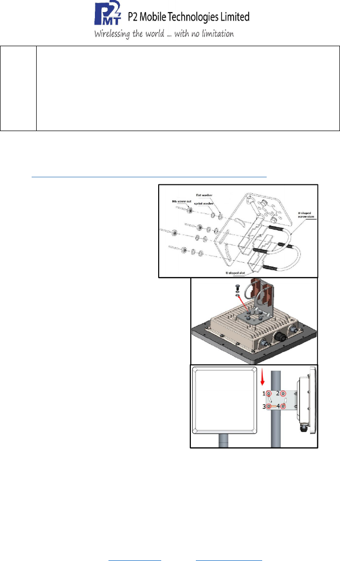
3 Mounting
3.1 Pole Mounting Procedure(Pole Size: Ø40-52mm)
1.
Firstly install the L shaped
clamp, with M6 screw nut,
spring washer and flat
washer. Four screws need be
installed.
2. Put the U shaped screw stem
and U shaped slot into the
hole. And then drive the M6
crew nut and M6 washer.
3. Install the clamp on the back of the
AP, with M6*12 screw bolt, M6
spring washer and M6 flat washer.
Four screw bolts need be installed.
4. Input M6*12 screw bolt and M6
washer into the hole on the back and
drive them.
5. Finally mount the AP on the pole as
shown in the picture. And drive the
screw nut tight with wrench.
-End of Quick Start Guide-

to provide a separation distance of at least 141.59cm
Federal Communications Commission (FCC) Interference Statement
This equipment has been tested and found to comply with the limits for a Class B digital device, pursuant
to Part 15 of the FCC Rules.
These limits are designed to provide reasonable protection against harmful interference in a residential
installation. This equipment generate, uses and can radiate radio frequency energy and, if not installed
and used in accordance with the instructions, may cause harmful interference to radio communications.
However, there is no guarantee that interference will not occur in a particular installation. If this
equipment does cause harmful interference to radio or television reception, which can be determined by
turning the equipment off and on, the user is encouraged to try to correct the interference by one of the
following measures:
Reorient or relocate the receiving antenna.
Increase the separation between the equipment and receiver.
Connect the equipment into an outlet on a circuit different from that to which the receiver is
connected.
Consult the dealer or an experienced radio/TV technician for help.
This device complies with Part 15 of the FCC Rules. Operation is subject to the following two conditions:
(1) This device may not cause harmful interference, and (2) this device must accept any interference
received, including interference that may cause undesired operation.
FCC Caution: Any changes or modifications not expressly approved by the party responsible for
compliance could void the user’s authority to operate this equipment.
RF exposure warning
This equipment complies with FCC radiation exposure limits set forth for an uncontrolled environment.
This equipment must be installed and operated in accordance with provided instructions and the
antenna(s) used for this transmitter must be installed
from all persons and must not be collocated or operating in conjunction with any other antenna or
transmitter.