PAC GS3LFP Panel LF Reader GS3 OneProx User Manual GS3 LF Panel Reader
PAC International Limited Panel LF Reader GS3 OneProx GS3 LF Panel Reader
PAC >
User Manual
GS3-LF Panel Reader
Installation Guide
171006 v1.02 DRAFT 89 Jul 2013

2

GS3-LF Panel Reader
Installation Guide
GS3-LF Panel-Leser
Installationsanleitung
GS3-LF Lecteur Monté sur Panneau
Guide d’installation
GS3-LF Lector para Montaje en Panel
Guía de instalación
GS3-LF Panelläsare
Installationsanvisninar
GS3-LF Paneellezer
Installatiehandleiding
GS3-LF Panelleser
Installasjonsguide
GS3-LF Lettore a pannello
Guida all’installazione
GS3-LF Leitor de painel
Guia de Instalação
GS3-LF Paneelilukija
Asennusopas
3
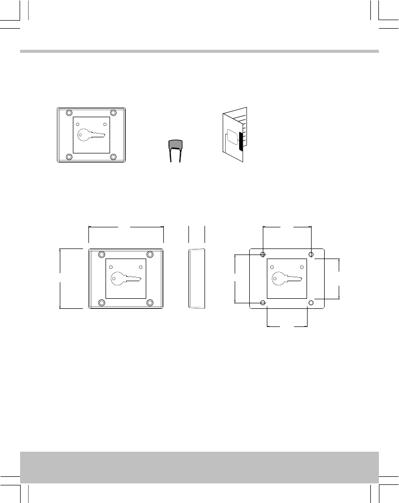
Parts · Teile · Pièces · Piezas · Delar · Delen · Deler · Componenti ·
Componentes · Osat
P/N 909020117
×1×1×1
MOV
Dimensions · Ausmaße · Dimensions · Dimensiones · Mått · Afmetingen ·
Dimensjoner · Dimensioni · Dimensões · Mitat
16
75
60 48.5
48.5
40
40
All dimensions mm · Alle Ausmaße in mm · Toutes dimensions en mm · Todas las dimensiones
en mm · Alla mått i mm · Alle afmetingen mm · Alle dimensjoner i mm · Tutte le dimensioni sono
in mm · Todas as dimensões em mm · Kaikki mitat ovat mm:nä
4
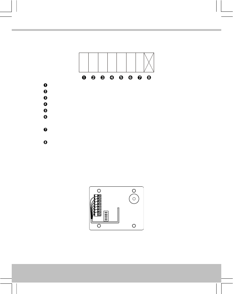
Connections · Anschlüsse · Connexions · Conexiones · Anslutningar ·
Aansluitingen · Tilkoplingar · Connessioni · Ligações · Liitännät
12-24V
D1/SIG
LED
0V/GND
D0/CLK
TAMP
SOUND
+V / 12V–24V
D1 / SIG
LED
0V / GND
D0 / CLK
Tamper · Sabotage · Effraction · Manip. fraud. · Manip. · Tamper · Sabotasje ·
Manomissione · Interferência · Ilkivalta
Sounder · Signaltongeber · Alarme sonore · Sonido · Ljudsignal · Alarm · Sirene ·
Ricevitore acustico · Dispositivo emissor de sons · Äänimerkinantaja
Do not use · Nicht verwenden · N’utiliser pas · No utilice · Använd inte · Niet
gebruiken · Ikke bruk · Non usare · Não utilizar · Älä käytä
Cable Routing · Kabelführung · Routage du câble · Recorrido del cable ·
Kabeldragning · Kabelroute · Kabelføring · Percorso dei cavi ·
Encaminhamento de cabos · Kaapelireititys
5
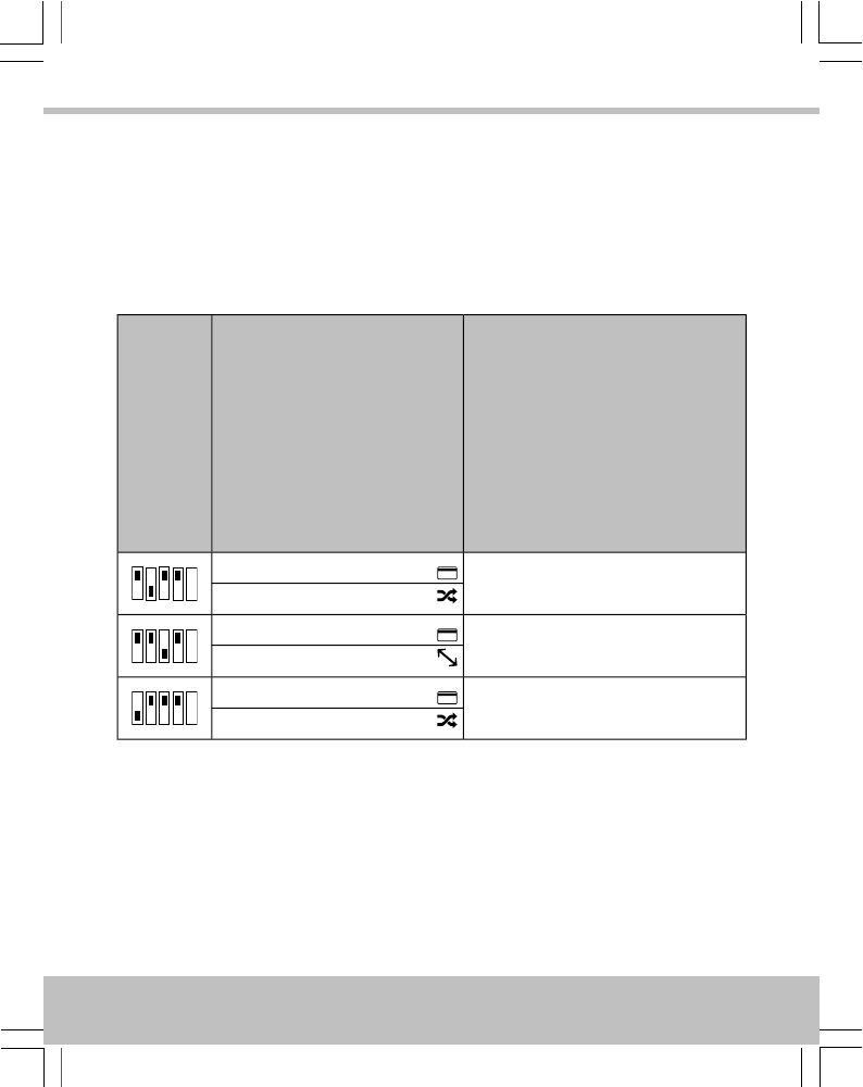
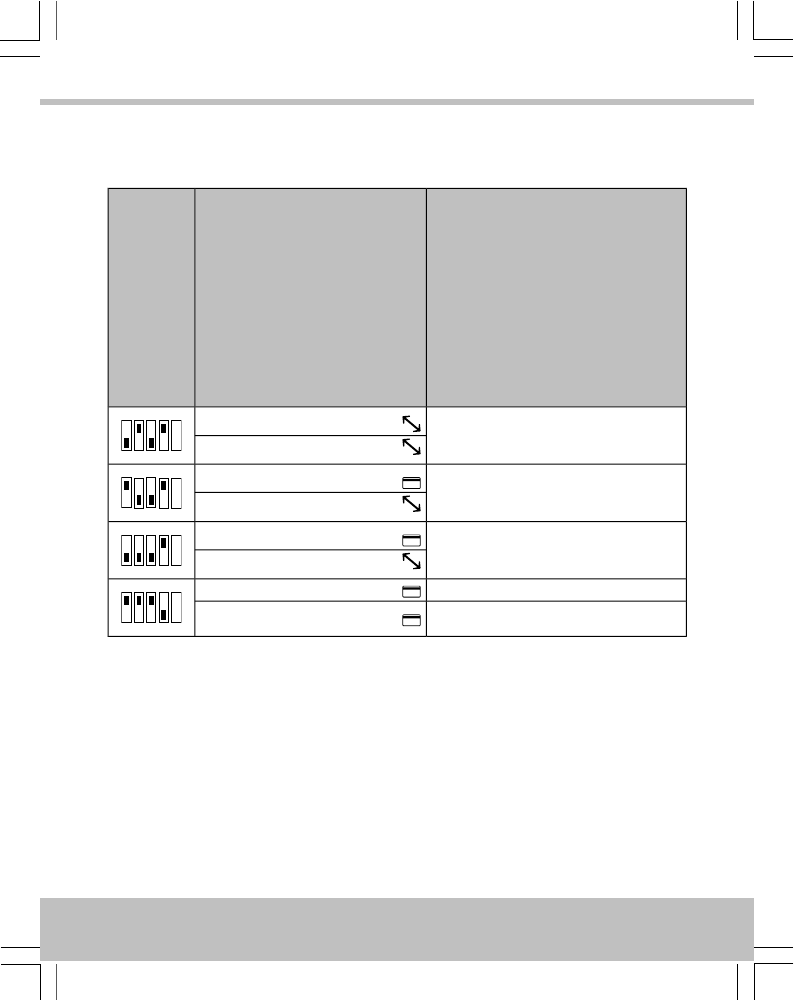
Output Format · Ausgabeformat · Format de Sortie · Formato de Salida ·
Utdataformat · Uitvoerformaat · Utdataformat · Formato uscita · Formato
de saída · Lähtömuoto
Default Settings · Standardeinstellungen · Paramètres standards · Ajustes estándares ·
Standardinställningar · Standaardinstellingen · Standardinnstillinger · Impostazioni
standard · Configurações padrões · Oletusasetukset
Output Format
Ausgabeformat
Format de sortie
Formato de Salida
Utdataformat
Uitvoerformaat
Utdataformat
Formato uscita
Formato de saída
Lähtömuoto
Card / Token
Karten / Token
Carte / Fiche
Tarjeta / Ficha
Kort / Nyckel
Kaart / Penning
Kort / Nøkkel
Scheda / Contrassegno
Cartão / Token
Kortti / Rahake
DIP
PAC
ON
1 2 3 4 5
PAC / KeyPAC
Wiegand Prox
PAC 64
ON
1 2 3 4 5
PAC / KeyPAC
Wiegand Prox
Magstripe
ON
1 2 3 4 5
PAC / KeyPAC
Wiegand Prox
6
Other Settings · Andere Einstellungen · Autres paramètres · Otros ajustes · Övriga
inställningar · Andere instellingen · Andre innstillinger · Altre impostazioni · Outras
configurações · Muut asetukset
Output Format
Ausgabeformat
Format de sortie
Formato de Salida
Utdataformat
Uitvoerformaat
Utdataformat
Formato uscita
Formato de saída
Lähtömuoto
Card / Token
Karten / Token
Carte / Fiche
Tarjeta / Ficha
Kort / Nyckel
Kaart / Penning
Kort / Nøkkel
Scheda / Contrassegno
Cartão / Token
Kortti / Rahake
DIP
Wiegand 26-bit
ON
1 2 3 4 5
PAC / KeyPAC
Wiegand Prox
Wiegand 34-bit
ON
1 2 3 4 5
PAC / KeyPAC
Wiegand Prox
Wiegand 74-bit
ON
1 2 3 4 5
PAC / KeyPAC
Wiegand Prox
Wiegand 74-bit
ON
1 2 3 4 5
PAC / KeyPAC
WiegandWiegand Prox
7
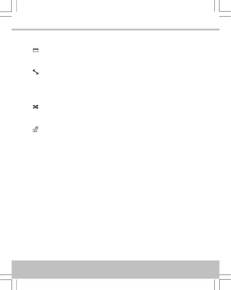
Symbols · Symbole · Symboles · Símbolos · Symboler · Symbolen · Symboler · Simboli ·
Símbolos · Symbolit
Data from card · Daten von Karte · Les données de la carte · Los datos de tarjeta ·
Data från kortet · Gegevens van de kaart · Data fra kortet · Dati dalla scheda · Os
dados do cartão · Tiedot kortti
Padded or truncated data · Daten aufgefüllt oder abgeschnitten · Les données sont
complétées ou tronquées · Los datos se rellenan o se truncan · Data utfylls eller
trunkeras · Gegevens worden opgevuld of afgekapt · Data polstres eller avkortes ·
Dati sono imbottiti o troncati · Os dados são preenchidos ou truncados · Tiedot on
pehmustettu tai katkaistu
Processed data · Daten verarbeitet · Les données sont traitées · Los datos se
procesan · Data bearbetas · Gegevens worden verwerkt · Data behandles · Dati
sono trattati · Os dados são processados · Tiedot käsitellään
OPS processed data · Daten verarbeitet als OPS · Les données sont traitées comme
OPS · Los datos se procesan como OPS · Data bearbetas som OPS · Gegevens
worden als OPS verwerkt · Data behandles som OPS · Dati sono trattati come OPS ·
Os dados são processados como OPS · Tiedot käsitellään ja salaus puretaan
8
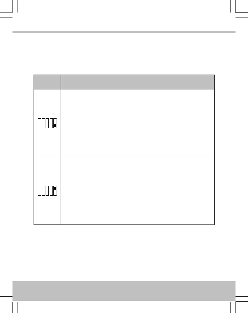
Reader Configuration · Konfiguration des Lesers · Configuration du
lecteur · Configuración de lector · Läsarens konfigurering ·
Lezerconfiguratie · Leserkonfigurasjon · Configurazione del lettore ·
Configuração do leitor · Lukijan konfiguraatio
Result · Ergebnis · Résultat · Resultado · Resultat · Resultaat · Resultat ·
Risultato · Resultado · Tulos
DIP
Reader beeps when token presented
Der Leser piept, wenn ein Token vorgezeigt wird.
Le lecteur émet un bip lorsque la fiche est présenté
Lector pita cuando una tarjeta es presentada
Läsaren piper när nyckel visas
Lezer piept als een token wordt aangeboden
Leseren piper når symbolet vises
Il lettore emette un segnale acustico quando viene presentato il contrassegno
O leitor emite sinais sonoros quando o token é apresentado
Lukija piippaa laitettaessa rahake laitteeseen
ON
1 2 3 4 5
Reader silent when token presented
Der Leser bleibt stumm, wenn ein Token vorgezeigt wird.
Le lecteur reste silencieux lorsque la fiche est présenté
Lector silencia cuando una tarjeta es presentada
Läsaren är tyst när nyckel visas
Lezer stil als een token wordt aangeboden
Leseren er stille når symbolet vises
Il lettore è silenzioso quando viene presentato il contrassegno
O leitor fica silencioso quando o token é apresentado
Lukija on hiljaa laitettaessa rahake laitteeseen
ON
1 2 3 4 5
9

English
Installation
1. Ensure your product comes with the items indicated on page 4; if not please contact
your dealer.
2. Mount reader within panel so that the front cover fits through the aperture and clamp
using nuts suitable for the studs.
3. Connect cable to circuit board — see page 5.
4. Set output format — see page 6.
5. Configure reader — see page 9.
6. Apply power when all readers are installed.
Notes
•The reader is designed to fit within a standard reader panel. Holes on the reader
accept M3 (metric) / #4 (UTS) posts.
•Mount readers >3′ / 1m apart, e.g. on either side of the door. Mounting on metal
surfaces will reduce the reading range.
•If the reader is being used to enter credential information to arm a system, the
reader must be located within 3′ / 1m of the panel’s main keypad or display.
•For outside readers, use corrosion-resistant fixings and apply silicone sealant to
the backplate before fixing to the wall.
•The supplied MOV (Metal Oxide Varistor, Anglia Components P/N B72207S250K101)
should be fitted across the power terminals of the lock to suppress back EMF. Any
suppression diodes fitted in the lock / lock circuit must be removed.
•Output format and reader configuration can be changed without disconnecting the
power supply. The reader automatically restarts with the new configuration.
10
English
Usage
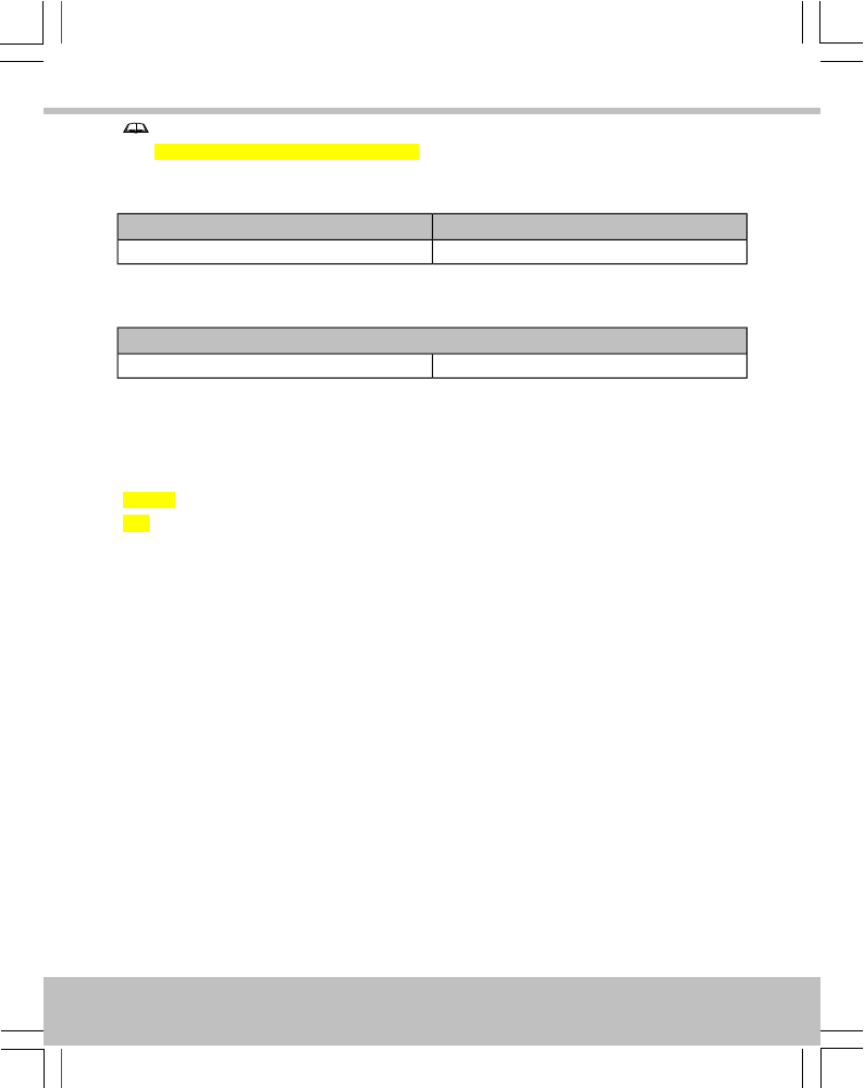
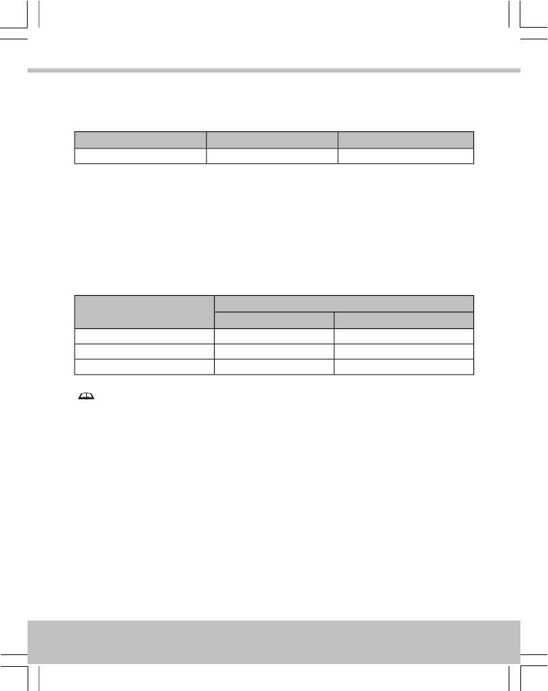
LEDs
Red / GreenGreenRed
Access deniedAccess permittedDefault
Sounder
•The reader sounds 4 rapid beeps when it is powered up or restarted.
•If specified, the reader beeps once when a token is presented.
Cable Lengths
PAC door controllers only
Distance from Reader to ControllerCable Gauge
PAC 202 / 512PAC 2100 / 2200
230′ / 70m *750′ / 250m7/0.2 0.34mm² 22AWG
230′ / 70m *1500′ / 500m16/0.2 0.5mm² 20AWG
230′ / 70m *3000′ / 1000m32/0.2 1.0mm² 18AWG
Notes
•These figures (*) are for readers powered from the controller. The cable distances
can be increased to 1650′ / 500m by locally powering the readers.
•Locally powered readers must be connected to a UL 603 power limited Class 2
supply for US, or a ULC S318 power limited Class 2 supply for Canada.
•If you use 22AWG / 0.34mm² cables, twist the wires and double them over before
inserting them in the crimps.
•Maximum cable distances will be less for readers which have been set to give
Wiegand output.
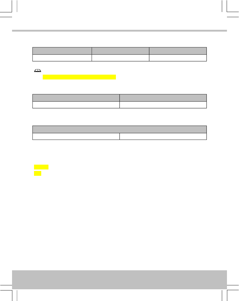
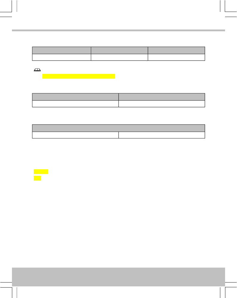
Specification
CurrentPowerReader Range
90mA12V–24V DCUp to 4.0″ / 100mm
11
English
Note
Maximum current draw is lower at 24V.
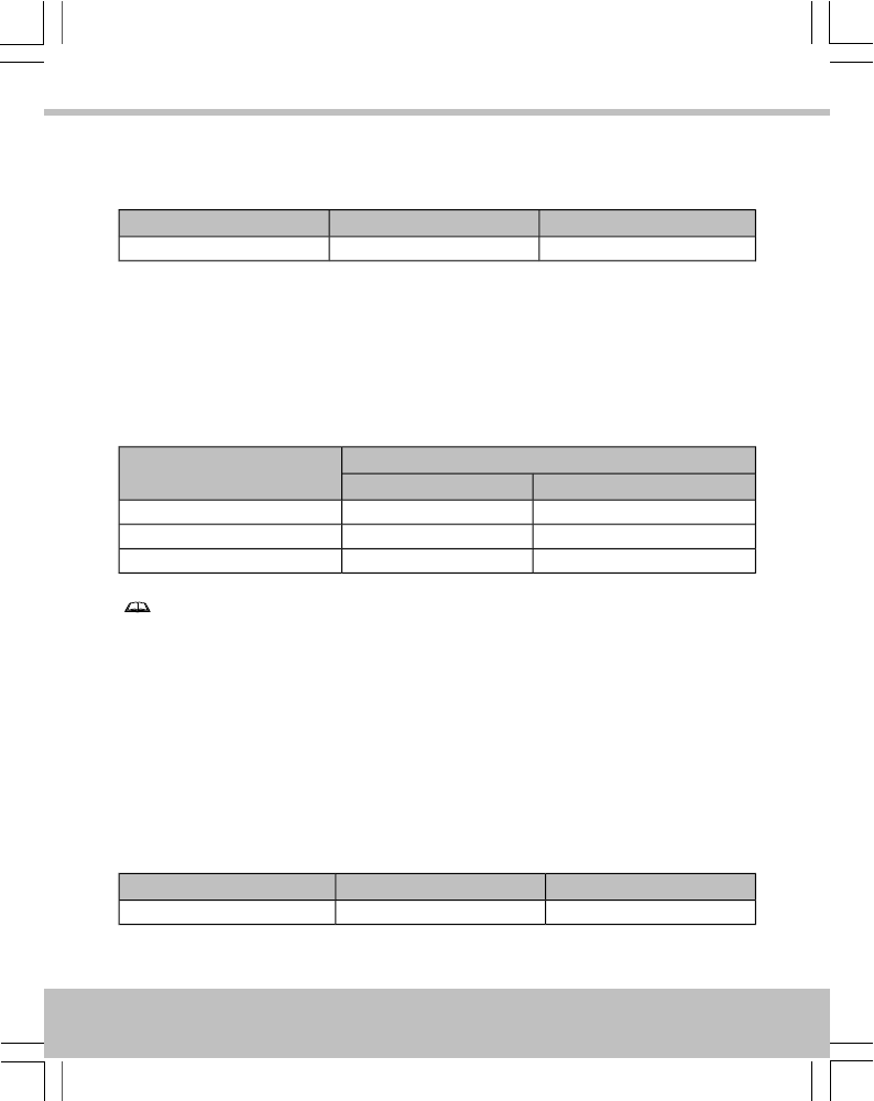
Temperature
StorageOperating
-40°C — +66°C / -40°F — +151°F-40°C — +66°C / -40°F — +151°F
Humidity
Operating for 24 hours
Tested at 93% for ULC S319.10-85% RH @ 30±2°C / 85±4°F
Ingress Protection
IP65 after installation — evaluated by lab separate from UL. Installer must adequately seal any
connections made.
Weight
90g
12
English

Deutsch
Installation
1. Überprüfen Sie, ob Ihr Produkt die Einzelteile angezeigt auf Seite 4; wenn nicht, wenden
Sie sich bitte an Ihren Händler.
2. Leser auf dem Panel befestigen, so dass die vordere Abdeckung durch die Öffnungen passt.
Mit Muttern sichern, die für die Stifte geeignet sind.
3. Kabel mit der Platine verbinden — siehe Seite 5.
4. Ausgabeformat einstellen — siehe Seite 6.
5. Leser konfigurieren — siehe Seite 9.
6. Strom erst anlegen, wenn alle Leser installiert sind.
Hinweise
•Der Leser passt in ein Standardlesergehäuse. Die Löcher am Leser passen für Pfosten
der Größe M3 (metrisch)/#4 (UTS).
•Leser im Abstand von > 1 m anbringen.
•Wird der Leser verwendet, um Zugangsinformationen zur Aktivierung eines Systems
einzugeben, muss sich der Leser innerhalb eines Umkreises von 1m um das Tastenfeld
oder die Anzeige des Panels befinden.
•Für Leser im Freien sind korrosionsbeständige Befestigungselemente und
Silikondichtungsmittel an den Anschlüssen verwenden.
•Der MOV sollte über den Stromanschlüssen des Schlosses montiert werden.
•Das Ausgabeformat und die Leserkonfiguration können geändert werden, ohne die
Stromversorgung zu unterbrechen. Der Leser startet automatisch erneut mit der
neuen Konfiguration.
13
Deutsch

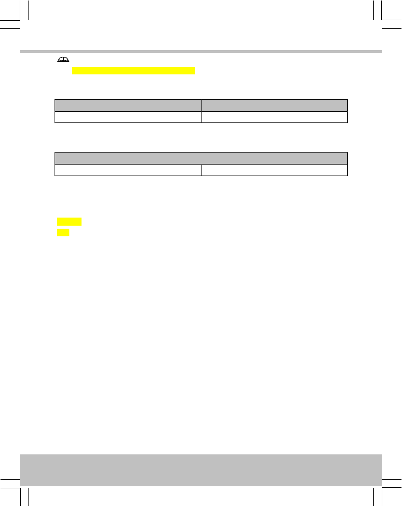
Verwendung
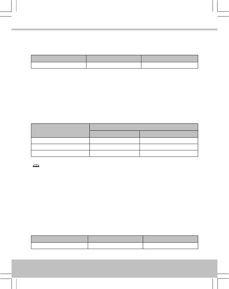
LEDs
Rot / GrünGrünRot
Zutritt verweigertZutritt gestattetStandard
Signaltongeber
•Der Leser gibt 4 schnelle Pieptöne aus, wenn er eingeschaltet oder neu gestartet
wird.
•Falls vorgegeben, piept der Leser einmal, wenn ein Token angezeigt wird.
Kabellängen
Nur PAC Türkontroller
Maximale Distanz zwischen Leser und KontrollerKabeltyp
PAC 202 / 512PAC 2100 / 2200
230′ / 70m *750′ / 250m7/0.2 0.34mm² 22AWG
230′ / 70m *1500′ / 500m16/0.2 0.5mm² 20AWG
230′ / 70m *3000′ / 1000m32/0.2 1.0mm² 18AWG
Hinweise
•Diese Werte (*) basieren auf der Annahme, dass der Leser über den Controller mit
Strom versorgt wird. Die Kabel können bis 500m durch eine lokale Stromversorgung
des Lesers verlängert werden.
•Leser mit örtlicher Stromversorgung müssen in den USA an einem
leistungsbegrenzten UL 603-Netzteil der Klasse 2 und in Kanada an einem
leistungsbegrenzten ULC S318-Netzteil der Klasse 2 angesteckt werden.
•Bei Nutzung eines 22AWG / 0.34mm² Kabels, verdrillen Sie die Drähte und doppeln
Sie diese bevor Sie die Enden in die Steckverbindungen einführen.
•Maximale Kabellängen können kürzer sein bei Lesern die als Wiegand-Leser
angebunden sind an den Kontroller.
14
Deutsch
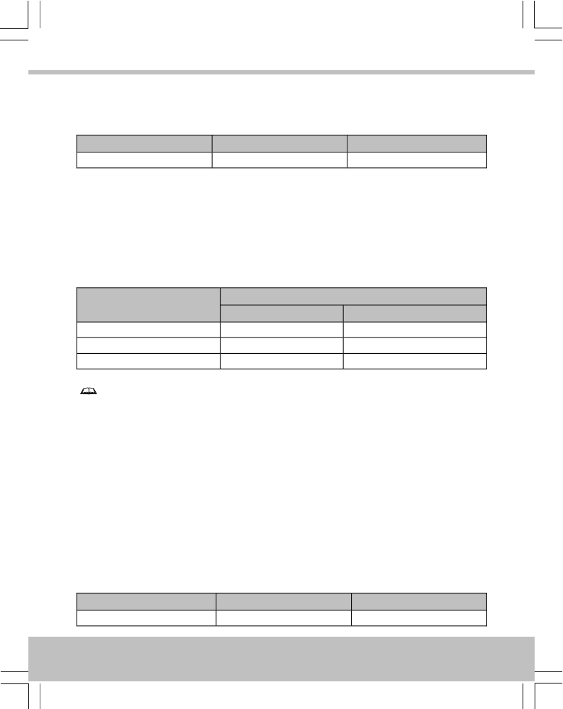
Spezifikation
StromSpannungLeserbereich
90mA12V–24V DCBis 100 mm
Hinweis
Maximum current draw is lower at 24V.
Temperatur
LagerungBetrieb
-40°C — +66°C-40°C — +66°C
Feuchtigkeit
Betrieb für 24 Stunden
Geprüft bei 93% für ULC S31910-85% RH @ 30±2°C / 85±4°F
Eindringschutz
IP65-Norm, komplett vergossen. Errichter müssen alle neuen Verbindungen ebenfalls versiegeln.
Weight
90g
15
Deutsch

Français
Installation
1. Vérifier que votre produit contient toutes les articles indiqués à la page 4. En cas de
pièce manquante, contacter votre distributeur.
2. Monter le lecteur sur les boulons de façon que le centre passe par l’ouverture et serrer à
bloc en utilisant des vis qui correspondent aux boulons.
3. Raccorder le câble au circuit — voir page 5.
4. Sélectionner le format de sortie — voir page 6.
5. Configurer le lecteur — voir page 9.
6. Alimenter le système une fois que tous les lecteurs ont été installés.
Remarques
•Ce lecteur a été développé pour le montage dans un panneau, tels qu’ils sont utilisés
dans des systèmes pour portes d’entrée. Les trous dans le lecteur acceptent des
boulons de serrage M3.
•Monter les lecteurs à de telle sorte qu’ils soient espacés d’1m, par exemple de
chaque coté de la porte. L’installation sur une surface métallique réduit la distance
de lecture.
•Si le lecteur est utilisé pour entrer les informations d’identification pour armer un
système, le lecteur doit être placé à moins de 1 m du clavier principal ou de
l’afficheur.
•Pour les lecteurs extérieurs, utiliser des fixations résistantes à la corrosion et
appliquer du silicone sur le support de fixation avant de le fixer au mur.
•Le MOV (varistor à oxyde métallique, Anglia Components nº B72207S250K101)
doit être installé en travers des bornes d’alimentation la serrure pour éviter le risque
de retour électrique. Toute diode ou self de blocage doivent être retirés.
•Le format de sortie et la programmation du lecteur peuvent être modifiés sans
couper l’alimentation. Le lecteur redémarre automatiquement avec la nouvelle
programmation.
16
Français

Utilisation
Diodes
Rouge / VertVertRouge
Accès refuséAccès autoriséPar défaut
Alarme sonore
•L’alarme sonore émet 4 bips courts lorsque le lecteur est alimenté ou redémarre.
•Si la fonction a été paramétrée, le lecteur émet un bip lorsque la fiche est présenté.
Longueur des câbles
Seulement pour les contrôleurs PAC.
Distance du lecteur au contrôleurÉpaisseur du câble
PAC 202 / 512PAC 2100 / 2200
230′ / 70m *750′ / 250m7/0.2 0.34mm² 22AWG
230′ / 70m *1500′ / 500m16/0.2 0.5mm² 20AWG
230′ / 70m *3000′ / 1000m32/0.2 1.0mm² 18AWG
Remarques
•Ces données (*) sont pour les lecteurs qui sont branches au contrôleur. La longueur
des câbles peut être augmentée de 500m si les lecteurs sont branches sur place.
•Pour les lecteurs qui sont branches sur place, l’alimentation doit être de classe 2,
limité en puissance, au conforme de l’UL 603 pour les USA; ou de classe 2, limité
en puissance, au conforme de l’ULC S318 pour le Canada.
•Si un câble 22AWG / 0.34mm² est utilise, plier les fils électriques en deux avant de
les insérer dans les sertisseurs.
•La longueur maximum des câbles sera moindre pour les lecteurs avec Wiegand.
Spécification
CourantAlimentationPortée du lecteur
90mA12V–24V DCJusqu’à 100mm
17
Français
Remarque
Maximum current draw is lower at 24V.
Température
RangementEn opération
-40°C — +66°C-40°C — +66°C
Humidité
En opération pendant 24 heures
Testé à 93% pour l’ULC S319.10-85% RH @ 30±2°C / 85±4°F
Protection contre l’entrée
IP65 après l’installation. Toutes connexions doivent être étanches par l’installateur.
Weight
90g
18
Français

Español
Instalación
1. Asegure que el producto se suministra con los artículos indicados en la página 4; en caso
contrario, rogamos que se ponga en contacto con el vendedor.
2. Instale el lector en el panel de tal forma que la cubierta delantera encaje a través de la
abertura y sujételo utilizando tuercas apropiadas para los tacos.
3. Conecte el cable a la placa de circuito — ver página 5.
4. Establecer formato de salida — ver página 6.
5. Configurar el lector — ver página 9.
6. Aplique alimentación cuando todos los lectores están instalados.
Notas
•El lector se ha diseñado para que encaje en un panel de lector estándar. Los orificios
del lector son compatibles con pernos M3 (medida) / #4 (UTS).
•Monte los lectores a una distancia entre sí >1 m, por ejemplo a cada lado de la
puerta. Montaje en superficies metálicas reducirá el rango de lectura.
•Si el lector está siendo utilizado para introducir la información de credenciales para
armar un sistema, el lector debe estar situado dentro de un rango de 1m del teclado
principal del panel o la pantalla.
•Para los lectores exteriores, utilice fijaciones anticorrosivas y sellador de silicona
en la placa de montaje antes de fijarlo a la pared.
•El MOV (varistor de metal-óxido, Anglia Components nº B72207S250K101) se
debería montar a través de los terminales de potencia de la cerradura para suprimir
un retorno de corriente. Todos los diodos de supresión instalados en el cerradero o
el circuito del cerradero deben ser eliminado.
•El formato de salida y la configuración de lector pueden ser cambiado sin
desconectar la fuente de alimentación. El lector se reinicia automáticamente con la
nueva configuración.
19
Español
Uso
LEDs
Rojo / VerdeVerdeRojo
Acceso denegadoAcceso permitidoPor defecto
Sonido
•El lector emite 4 pitidos rápidos cuando el lector se alimenta o se reinicia.
•Si se especifica, el lector suena una vez cuando una tarjeta es presentada.
Longitudes del Cable
Solo válida para controladoras PAC.
Distancia desde el Lector a ControladorGrosor del Cable
PAC 202 / 512PAC 2100 / 2200
230′ / 70m *750′ / 250m7/0.2 0.34mm² 22AWG
230′ / 70m *1500′ / 500m16/0.2 0.5mm² 20AWG
230′ / 70m *3000′ / 1000m32/0.2 1.0mm² 18AWG
Notas
•Estos datos (*) son válidos para lectores alimentados desde la controladora. Las
distancias del cable pueden ser incrementadas a 500m utilizando lectores con
alimentación local.
•Los lectores de alimentación local deben ser conectados a una fuente de alimentación
limitadas clase 2 UL603 para USA, o a una fuente de alimentación limitada clase
2 ULC S318 para Canadá.
•Si se usa un cable de 22AWG / 0.34mm² retorcer los cables y doblarlos para
insertarlos en un terminal.
•La máxima distancia de cable será menor para los lectores los cuales hayan sido
configurados para dar una salida Wiegand.
Especificaciones
CorrienteAlimentaciónRango del lector
90mA12V–24V DCHasta 100mm
20
Español

Nota
Maximum current draw is lower at 24V.
Temperatura
AlmacenamientoOperando
-40°C — +66°C-40°C — +66°C
Humedad
Operando para 24 horas
Testado al 93 % según ULC S319.10-85% RH @ 30±2°C / 85±4°F
Protección de Acceso
Hermetizar para IP65 después de la instalación. El instalador debe hermetizar y proteger cualquier
conexión que se haga.
Weight
90g
21
Español
Svensk
Installation
1. Kontrollera att din produkt åtföljs artikeln antyd på sida 4. Kontakta din återförsäljare
om inte.
2. Montera läsaren i panelen med muttrar avpassade för pinnbultarna så att framstycket
passar mellan öppningen och klämman.
3. Koppla kabeln till kretskortet — se sidan 5.
4. Ställ in utdataformat — se sidan 6.
5. Konfigurera läsaren — se sidan 9.
6. Slå till strömförsörjningen när alla läsare är installerade.
Anmärkningar
•Läsaren är utformad för att passa i en standardpanel för läsare. Hålen på läsaren
är avpassade för M3 skruv.
•Montera läsarna 1 meter isär, exempelvis på vardera sidan om dörren. Om läsarna
monteras på en metallyta reduceras läsområdet.
•Om läsaren används för att ange autentiseringsuppgifter för systemaktivering måste
läsaren placeras inom 1 meter från panelens huvuddisplay eller knappsats.
•För utomhusläsare ska korrosionståliga fästanordningar användas och fästplattan
ska tätas med silikontätningar innan den fästs vid väggen.
•Metalloxidvaristorn (Anglia Components P/N B72207S250K101) ska monteras
över låsets spänningsanslutningar för att undertrycka EMF. Undertryckdioder i
låset/låskretsen måste avlägsnas.
•Utdataformat och läsarkonfigurering kan ändras utan att koppla bort
strömförsörjningen. Läsaren startas om automatiskt med den nya konfigureringen.
22
Svensk

Användning
Lysdioder
Röd / GrönGrönRöd
Åtkomst nekadÅtkomst beviljadStandard
Ljudsignal
•Läsaren avger 4 snabba pip när den startas upp eller startas om.
•Om det anges särskilt kan läsaren pipa när nyckel visas.
Kabellängder
Endast för PAC styrenheter
Avstånd från Läsare till CentralKabeldata
PAC 202 / 512PAC 2100 / 2200
230′ / 70m *750′ / 250m7/0.2 0.34mm² 22AWG
230′ / 70m *1500′ / 500m16/0.2 0.5mm² 20AWG
230′ / 70m *3000′ / 1000m32/0.2 1.0mm² 18AWG
Anmärkningar
•Dessa data (*) gäller för läsare som är strömförsörjda från centralen. Kabellängden
kan ökas till 500m om man strömförsörjer lokalt.
•Lokalt strömförsörjda läsare måste kopplas till UL 603 klass 2 nätaggregat för USA
eller ULC S318 klass 2 nätaggregat för Kanada.
•Om du använder 22AWG/0.34mm² kablar vrider och viker du sladdarna innan de
stoppas i klämman.
•Max kabelavstånd kommer att vara lägre för Wiegandläsare.
Specifikation
StrömSpänningLäsområde
90mA12V–24V DCUpp mot 100 mm
23
Svensk

Anmärkning
Maximum current draw is lower at 24V.
Temperatur
LagringDrift
-40°C — +66°C-40°C — +66°C
Luftfuktighet
Körs i 24 timmar
Testad vid 93 % för ULC S319.10-85% RH @ 30±2°C / 85±4°F
Kapsling
IP65 efter installation. Installatör måste täta samtliga genomföringar.
Weight
90g
24
Svensk

Nederlands
Installatie
1. Controleer of met het product de punten die op pagina 4 worden vermeld. Indien dit niet
het geval is, neem dan contact op met de leverancier.
2. Monteer de lezer binnen het paneel zodat het frontdeksel door de opening past en klem
vast met behulp van moeren die geschikt zijn voor de tapeinden.
3. Verbind kabel met schakelbord — zie pagina 5.
4. Stel outputformaat in — zie pagina 6.
5. Configureer lezer — zie pagina 9.
6. Schakel stroom in als alle lezers zijn geïnstalleerd.
Opmerkingen
•De lezer is geschikt om in een standaard lezerpaneel te passen. Openingen op de
lezer aanvaarden M3 (metrisch) / #4 (UTS) posts.
•Plaats de sensors minstens 1 m uit elkaar.
•Als de lezer wordt gebruikt om verificatiegegevens in te voeren om het systeem te
bewapenen, moet de lezer zich binnen een afstand van 1 m van het hoofdtoetsenbord
of -scherm van het paneel bevinden.
•Voor sensors die buiten worden gemonteerd dienen corrosiebestendige
bevestigingsmiddelen en een siliconen afdichtmiddel op de aansluitpunten gebruikt
te worden.
•Breng de MOV over de aansluitingen van het slot aan.
•Outputformaat en lezerconfiguratie kunnen worden gewijzigd zonder de stroom te
onderbreken. De lezer start automatisch opnieuw op met de nieuwe configuratie.
25
Nederlands
Gebruik
LEDs
Rood / GroenGroenRood
Toegang geweigerdToegang toegelatenStandaard
Alarm
•De lezer geeft 4 snelle pieptonen weer als hij aan de stroom is aangesloten of
opnieuw is opgestart.
•Indien gespecificeerd, piept de lezer een keer als een token is aangeboden.
Kabellengte
PAC deurcontrollers alleen
Afstand tot de LezerKabel Specificaties
PAC 202 / 512PAC 2100 / 2200
230′ / 70m *750′ / 250m7/0.2 0.34mm² 22AWG
230′ / 70m *1500′ / 500m16/0.2 0.5mm² 20AWG
230′ / 70m *3000′ / 1000m32/0.2 1.0mm² 18AWG
Opmerkingen
•Deze specificaties (*) zijn van toepassing indien de lezers vanuit de controller worden
gevoed. De kabellengte kan worden vergroot naar 500m door de lezers lokaal te
voeden.
•Plaatselijk aangedreven lezers moeten verbonden zijn met een UL 603 toevoer,
beperkt tot klasse 2 voor de VS of een ULC S318 toevoer, beperkt tot klasse 2
voor Canada.
•Indien u een 22AWG / 0.34mm² kabel gebruikt, twist de draad uiteinden en vouw
deze dubbel alvorens deze in een draadhuls te plaatsen.
•De maximale kabellengte is bij het gebruik van PAC lezers die ingesteld zijn op een
Wiegand formaat aanzienlijk minder. Raadpleeg bij twijfel uw leverancier.
26
Nederlands
Specificaties
StroomSpanningLezerbereik
90mA12V–24V DCTot 100mm
Opmerking
Maximum current draw is lower at 24V.
Temperatuur
OpslagBereik
-40°C — +66°C-40°C — +66°C
Vochtigheid
Werkt 24 uur
Getest aan 93% voor ULC S319.10-85% RH @ 30±2°C / 85±4°F
Stofbescherming
Geseald conform IP65. De installateur dient zorg te dragen voor een correcte waterdichte
afdichting van de bekabeling na installatie.
Weight
90g
27
Nederlands

Norsk
Installasjon
1. Forsikre deg om at produktet leveres med delene angitt på side 4. Kontakt forhandleren
hvis det ikke er tilfellet.
2. Monter leseren innenfor panelet slik at frontdekselet passer gjennom åpningen og klemmene
bruker muttere som passer til stenderne.
3. Koble kabelen til kretskortet — se side 5.
4. Stille inn utdata format — se side 6.
5. Konfigurere leser — se side 9.
6. Koble til strømmen når alle lesere er installert.
Merknader
•Leseren er utviklet for å passe i et standard leserpanel. Hullene på leseren godtar
M3 (metrisk)/# 4 (UTS) innlegg.
•Lesere skal monteres med over 1 meters mellomrom.
•Hvis leseren brukes til å angi påloggingsopplysning for å aktivere et system, må
leseren være plassert innenfor 1m til panelet viktigste tastatur eller visning.
•For utendørslesere skal det brukes korrosjonsbestandige festeanordninger og
silikontetning på kontaktene.
•MOV-varistoren skal monteres over låsens strømkontakter.
•Utdataformat og leserkonfigurasjon kan endres uten å koble fra strømforsyningen.
Leseren starter automatisk med den nye konfigurasjonen.
28
Norsk

Bruk
Lysdioder
Rød / GrønnGrønnRød
Tilgang avslåttTilgang tillattStandard
Sirene
•Leseren lyder 4 ganger raskt når den slås på eller startes på nytt.
•Dersom spesifisert, piper leseren en gang når symbolet vises.
Kabel Lengde
Kun for PAC kontrollere
Avstand fra Leser til SentralKabel Dimensjon
PAC 202 / 512PAC 2100 / 2200
230′ / 70m *750′ / 250m7/0.2 0.34mm² 22AWG
230′ / 70m *1500′ / 500m16/0.2 0.5mm² 20AWG
230′ / 70m *3000′ / 1000m32/0.2 1.0mm² 18AWG
Merknader
•Denne oversikten (*) er for lesere som strømforsynes fra sentralen. Kabellengden
kan økes til 500m ved egen strømforsyning på leser.
•Lokalt drevne lesere må kobles til en UL 603 begrenset strømklasse 2 forsyning
for USA, eller en ULC S318 begrenset strømklasse 2 forsyning for Canada.
•Hvis du bruker 22AWG / 0.34mm² kabel må parene tvinnes og dobles opp for de
kobles til utstyret.
•Maksimal kabellengde vil være mindre for lesere som er satt til Wiegand grensenitt.
Spesifikasjon
StrømSpenningRekkevidde leser
90mA12V–24V DCOpp til 100 mm
29
Norsk

Merknad
Maximum current draw is lower at 24V.
Temperatur
LagringMiljø
-40°C — +66°C-40°C — +66°C
Luftfuktighet
Drift i 24 timer
Testet ved 93 % for ULC S319.10-85% RH @ 30±2°C / 85±4°F
Inntrengningsbeskyttelsen
IP65 tetthetsgrad. Installatør må videre påse at alle koblinger forsegles skikkelig.
Weight
90g
30
Norsk

Italiano
Installazione
1. Assicurarsi che il prodotto sia stato fornito con i componenti elencati a pagina 4; in caso
contrario, contattare la concessionaria.
2. Montare il lettore sul pannello in modo che il coperchio anteriore corrisponda all’apertura
e fissare con dati adatti ai prigionieri.
3. Collegare il cavo alla scheda dei circuiti — vedere a pagina 5.
4. Impostare il formato dell’uscita — vedere a pagina 6.
5. Configurare il lettore — vedere a pagina 9.
6. Quando tutti i lettori sono installati, accendere l’alimentazione.
Note
•Il lettore è progettato per adattarsi a un pannello standard per lettore. I fori del
lettore accettano colonnine M3 (metriche) / #4 (UTS).
•Montare i lettori a distanza di >1 m l’uno dall’altro, ad esempio ai lati della porta.
Il montaggio su superfici metalliche riduce la portata di lettura.
•Se il lettore viene usato per immettere le informazioni sulle credenziali in modo da
armare un sistema, il lettore deve essere collocato a meno di 1 m dalla tastiera o
display principale del pannello.
•Per i lettori esterni, usare dispositivi di fissaggio resistenti alla corrosione e applicare
del sigillante al silicone sulla piastra posteriore prima del fissaggio alla parete.
•Il MOV (Metal Oxide Varistor/Varistore a ossidi metallici, codice Anglia Components
B72207S250K101) deve essere inserito tra i morsetti del dispositivo di bloccaggio
per sopprimere le EMF sul retro. Tutti i diodi soppressori inseriti sul circuito da
blocco a blocco devono essere rimossi.
•Il formato di uscita e la configurazione del lettore possono essere modificati senza
staccare l’alimentazione. Il lettore riavvia automaticamente la nuova configurazione.
31
Italiano
Utilizzo
LED
Rosso / VerdeVerdeRosso
Accesso negatoAccesso permessoPredefinito
Ricevitore acustico
•Quando viene alimentato o riavviato, il lettore emette 4 rapidi segnali acustici.
•Se specificato, il lettore emette un segnale acustico quando viene presentato un
contrassegno.
Lunghezze dei cavi
Solo controller PAC per porta
Distanza dal lettore all’unità di controlloCalibro dei cavi
PAC 202 / 512PAC 2100 / 2200
230′ / 70m *750′ / 250m7/0.2 0.34mm² 22AWG
230′ / 70m *1500′ / 500m16/0.2 0.5mm² 20AWG
230′ / 70m *3000′ / 1000m32/0.2 1.0mm² 18AWG
Note
•Queste cifre (*) sono per i lettori alimentati dall’unità di controllo. Le distanze dei
cavi possono essere aumentate fino a 500 m alimentando localmente i lettori.
•I lettori alimentati localmente devono essere connessi a un alimentatore con
limitazione di potenza UL 603 Classe 2 per gli USA, o a un alimentatore con
limitazione di potenza ULC S318 Classe 2 per il Canada.
•Se si usano cavi 22AWG / 0,34 mm², torcere e ripiegare i fili prima di crimparli.
•Le distanze massime dei cavi sono inferiori per i lettori impostati in modo da fornire
un’uscita Wiegand.
Specifiche
CorrenteAlimentazionePortata del lettore
90mA12V–24V DCFino a 100 mm
32
Italiano

Nota
Maximum current draw is lower at 24V.
Temperatura
StoccaggioOperativa
-40 °C — +66 °C-40 °C — +66 °C
Umidità
Funzionamento per 24 ore
Collaudato al 93% secondo ULC S319.10-85% RH @ 30±2°C / 85±4°F
Protezione ingresso
IP65 dopo l’installazione. L’installatore deve sigillare adeguatamente tutte le connessioni
effettuate.
Weight
90g
33
Italiano

Português
Instalação
1. Certifique-se de que o produto inclui os itens indicados na página 4; caso não inclua,
contacte o seu revendedor.
2. Monte o leitor no painel de forma a que a cobertura frontal caiba através da abertura e
prenda utilizando porcas adequadas para os pernos.
3. Ligue o cabo à placa de circuitos — consulte a página 5.
4. Defina o formato de saída — consulte a página 6.
5. Configurar o leitor — consulte a página 9.
6. Ligue a alimentação quando todos os leitores estiverem instalados.
Notas
•O leitor está concebido para poder ser colocado num painel de leitura standard. Os
orifícios no leitor aceitam pinos M3 (métricos) / #4 (UTS).
•Monte os leitores a uma distância de >1 m entre si, por exemplo em ambos os
lados da porta. A montagem em superfícies metálicas reduzirá o alcance de leitura.
•Caso o leitor esteja a ser usado para introduzir informações de credenciais para
armar um sistema, o leitor deverá estar localizado a 1 m do visor ou teclado principal
do painel.
•Para leitores exteriores, utilize fixações resistentes à corrosão e aplique vedante
em silicone à placa posterior antes de fixar à parede.
•O VOM (Varistor de Óxido Metálico, Componentes Anglia P/N B72207S250K101)
fornecido deverá ser colocado nos terminais de alimentação do bloqueio para suprimir
qualquer força contra-eletromotriz. Quaisquer díodos de supressão colocados no
bloqueio / circuito de bloqueio deverão ser removidos.
•O formato de saída e a configuração do leitor podem ser alterados sem desligar a
fonte de alimentação. O leitor reinicia automaticamente com a nova configuração.
34
Português
Utilização
LEDs
Vermelho / VerdeVerdeVermelho
Acesso negadoAcesso permitidoPredefinido
Dispositivo emissor de sons
•O leitor emite 4 sinais sonoros rápidos quando é ligado ou reiniciado.
•Se especificado, o leitor soa uma vez quando é apresentado um token.
Comprimentos de cabo
Apenas controladores de porta PAC
Distância do leitor ao controladorBitola do cabo
PAC 202 / 512PAC 2100 / 2200
230′ / 70m *750′ / 250m7/0.2 0.34mm² 22AWG
230′ / 70m *1500′ / 500m16/0.2 0.5mm² 20AWG
230′ / 70m *3000′ / 1000m32/0.2 1.0mm² 18AWG
Notas
•Estes números (*) são para leitores alimentados a partir do controlador. As distâncias
de cabo podem ser aumentadas para 500 m alimentando localmente os leitores.
•Os leitores alimentados localmente devem ser ligados a uma alimentação Classe 2
de potência limitada UL 603 para os E.U.A., ou a uma alimentação Classe 2 de
potência limitada ULC S318 para o Canadá.
•Caso utilize cabos 22AWG / 0,34mm², rode os fios e dobre-os sobre si mesmos
antes de os inserir nos orifícios.
•As distâncias de cabo máximas serão inferiores para leitores que tenham sido
definidos para apresentar a saída Wiegand.
Especificação
CorrentePotênciaAlcance do leitor
90mA12V–24V DCAté 100 mm
35
Português

Nota
Maximum current draw is lower at 24V.
Temperatura
ArmazenamentoFuncionamento
-40°C — +66°C-40°C — +66°C
Humidade
Funcionamento durante 24 horas
Testado a 93% para ULC S319.10-85% RH @ 30±2°C / 85±4°F
Proteção contra entradas
IP65 após a instalação. O dispositivo de instalação deverá selar adequadamente quaisquer
ligações feitas.
Weight
90g
36
Português

Suomi
Asennus
1. Varmista, että tuotteesi on toimitettu sivulla 4 näytetyillä nimikkeillä; jos ei, ota yhteys
edustaja.
2. Kiinnitä lukija paneeliin siten, että etusuoja sopii reiän läpi ja kiinnitä käyttäen tappeihin
sopivia muttereita käyttämällä.
3. Liitä kaapeli piirilevyyn — ks. sivu 5.
4. Aseta lähtömuoto — ks. sivu 6.
5. Konfiguroi lukija — ks. sivu 9.
6. Kytke virta päälle, kun kaikki lukijat on asennettu.
Huomaa
•Lukija on suunniteltu sopimaan vakio lukijapaneeliin. Lukijan rei’issä voidaan käyttää
M3 (metrijärj.) / #4 (UTS) liitäntänastoja.
•Asenna lukijat >1 m toisistaan, esim. oven kummallekin puolelle. Kiinnitys
metallipinnoille pienentää lukualuetta.
•Jos lukijaa käytetään antamaan valtuutustiedot järjestelmän virittämiseksi, lukijan
on oltava vähintään 1 m paneelin päänäppäimistöstä tai näytöstä.
•Ulos asennetuissa lukijoissa, käytä korroosion estäviä kiinnittimiä ja laita takalevyyn
silikonitiivistettä ennen sen kiinnittämistä seinään.
•Toimitettu MOV (metallioksidivaristori, Anglia Components, osanro.
B72207S250K101) on asennettava lukon sähkösyöttöliitinten välille
sähkömagneettisten häiriöiden vaimentamiseksi. Kaikki lukkoon kiinnitetyt
vaimennusdiodit / lukkopiiri on poistettava.
•Lähtömuoto ja lukijan konfiguraatio voidaan muuttaa irrottamatta sähkösyöttöä.
Lukija käynnistyy automaattisesti uudestaan uudella konfiguraatiolla.
37
Suomi

Käyttö
LEDit
Punainen / vihreäVihreäPunainen
Pääsy estettyPääsy sallittuOletus
Äänimerkinantaja
•Lukija antaa laitettaessa virta päälle tai käynnistettäessä uudelleen 4 nopeaa
piippausta.
•Jos määritetty, lukija antaa yhden äänimerkin laitettaessa rahake laitteeseen.
Kaapelipituudet
Vain PAC-oviohjaimet
Etäisyys lukijasta ohjaimeenKaapelimitta
PAC 202 / 512PAC 2100 / 2200
230′ / 70m *750′ / 250m7/0.2 0.34mm² 22AWG
230′ / 70m *1500′ / 500m16/0.2 0.5mm² 20AWG
230′ / 70m *3000′ / 1000m32/0.2 1.0mm² 18AWG
Huomaa
•Nämä luvut (*) ovat ohjaimesta virtansa saaville lukijoille. Kaapelipituus voidaan
lisätä arvoon 500m paikallisesti sähkösyötetyille lukijoille.
•Paikallisesti sähkösyötetyt lukijat on liitettävä Yhdysvalloissa UL 603 luokan 2
sähkösyöttöön ja Kanadassa ULC S318 luokan 2 sähkösyöttöön.
•Jos käytät 22AWG / 0,34 mm² johtoja, kierrä johdot ja käännä ne kaksinkerroin
ennen niiden työntämistä pitimiin.
•Kaapelien enimmäispituudet ovat pienemmät lukijoille, jotka on asetettu antamaan
Wiegand-lähdön.
Tekniset tiedot
VirtaTehoLukijan etäisyys
90mA12V–24V DCEnintään 100 mm
38
Suomi

Huomaa
Maximum current draw is lower at 24V.
Lämpötila
SäilytysKäyttö
-40 °C — +66 °C-40 °C — +66 °C
Suht. kosteus
24 tunnin käyttö
Testattu 93 %:ssa ULC S319 varten10-85% RH @ 30±2°C / 85±4°F
Kotelointi
IP65 asennuksen jälkeen. Asentajan on tiivistettävä riittävästi kaikki tehdyt liitännät.
Weight
90g
39
UL / ULC Outdoor / Indoor rated.
•UL 294 5th Ed. Attack Class 3 — Access Control Systems Unit
•ULC S319-05 Class 3 — Electronic Access Control Systems
•UL 1610 — Central-Station Burglar-Alarm Units
•ULC S304 — Central and Monitoring Station Burglar Alarm Units
•UL 1076 — Proprietary Burglar Alarm Units and Systems
•ULC C1076 — Proprietary Burglar Alarm Units and Systems
•UL 609 — Local Burglar Alarm Units and Systems
•ULC S303 — Standards for Local Burglar Alarm Units and Systems
Notes
•This product’s compliance to ULC S319 will be invalidated through the use of any
add-on, expansion, memory, or other module manufactured or supplied by the
manufacturer or manufacturer’s representative.
•For UL 609 the reader is not to be used for low battery indication and audible exit /
entry delay. The Listed approved keypad is to be used to display these functions.
•This product cannot be used to receive or display acknowledgment signals from
central station.
40
Declaration of Conformity is available on request.
In addition to meeting the minimum CE requirements, this product has been tested to the
following:
•EN 50133 — Access Point Reader, Recognition Class 2, Environmental Class IIIA,
IP65, IK 04
EN 50130-4 (per 50131 and 50133)
EN 50130-5 (per 50131 and 50133)
Do not discard this product along with other household waste; it must be collected and treated
separately.
41
FCC
FCC ID: OQLGS3LFP
This device complies with part 15 of the FCC Rules. Operation is subject to the following two
conditions: (1) This device may not cause harmful interference, and (2) this device must accept
any interference received, including interference that may cause undesired operation.
In compliance with FCC requirement 15.27 no special accessories are required in order to
comply with part 15 of the FCC regulations. Changes or modifications not expressly approved
by Stanley Security Products could void the user’s authority to operate the equipment.
IC
IC ID: 7309A-OQLGS3LFP
This Class B digital apparatus complies with Canadian ICES-003.
This device complies with Industry Canada licence-exempt RSS standard(s). Operation is subject
to the following two conditions: (1) this device may not cause interference, and (2) this device
must accept any interference, including interference that may cause undesired operation of
the device.
Cet appareil numérique de la classe B est conforme à la norme NMB-003 du Canada.
Le présent appareil est conforme aux CNR d’Industrie Canada applicables aux appareils radio
exempts de licence. L’exploitation est autorisée aux deux conditions suivantes : (1) l’appareil
ne doit pas produire de brouillage, et (2) l’utilisateur de l’appareil doit accepter tout brouillage
radioélectrique subi, même si le brouillage est susceptible d’en compromettre le fonctionnement.
Canadian Point of Contact
•David P. Jones, President / Paul A. Nickel, Vice President
•Sonitrol Distribution Canada, Inc.
5875 Kennedy Road
Mississauga, Ontario L4Z 2G3
Canada
Tel: +1 905-890 7727
42
43

United Kingdom:
PAC — A Stanley Security Products Business
1 Park Gate Close, Bredbury, Stockport, Cheshire, SK6 2SZ
Contact:
Tel: +44 (0) 161 406 3400
Fax: +44 (0) 161 430 8658
E-mail: customerservices@stanleysecurityproducts.com
Web: www.stanleysecurityproducts.co.uk
Technical Support:
Tel: (U.K.) 0845 206 3400 (Int.) +44 (0) 161 430 1340
Fax: +44 (0) 161 406 6749
E-mail: pacsupp@sbdinc.com
Knowledge Base: www.stanleysecurityproducts.co.uk/support
United States of America:
Stanley Security Products
Contact / Technical Support:
Tel: 800 414-3038
Fax: 800 414-3039
E-mail: support@stanleypac.com
Web: www.stanleysecurityproducts.com
Knowledge Base: www.stanleysecurityproducts.co.uk/support
Stanley is a registered trademark of The Stanley Works, Inc. Unless otherwise indicated,
the trademarks and logos displayed are the property of Stanley Security Solutions — Europe Ltd
and / or their subsidiary companies.