Users manual
Draft 1 20441 Operation and Installation Instructions © 1999
Page 1
INTERNATIONAL Data Sheet
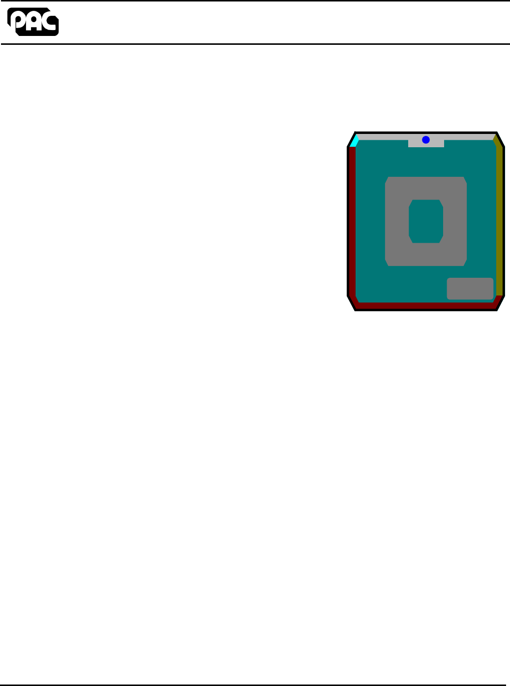
Low Profile Multi-Output Format Proximity Reader
Operation and Installation Instructions
Features
•
••
•Easy Installation
•
••
•Reads ISO Cards (PAC P.N. 21030)
•
••
•Status LED indicates Access Authorized
•
••
•Rated for Indoor and Outdoor use
•
••
•Offered in Dark Grey or Off-White Colors
•
••
•Outputs in PAC Output Format, Wiegand
26, 32, 64 Bit Format, ANSI Magstripe
Description
The KeyPAC Low Profile (PAC Part Number 20441) proximity reader is an accessory commonly
used on a majority of access control systems. The Low Profile uses pre-encoded ISO proximity
cards (PAC Part Number 21030). Each card is encoded with a unique code that outputs a serial
number to the access control system.
The Low Profile is weather resistant and suitable for indoor or outdoor use. Cards are read at a
distance of up to 4 inches.
This reader is also available in off-white by ordering PAC Part Number 20446.
How the Reader is Used
The Low Profile is connected to a reader input on a door controller, time and attendance unit or
control panel, that can except a PAC format, Wiegand 26/ 32/ 64 Bit format or ANSI Magstripe
format. The Low Profile detects and reads the unique embedded coding from each ISO card when
it is presented within 4 inches of the reader. The Low Profile will then output this coding, that has
been received by the card, to the receiving door controller, time and attendance unit or control
panel.
How the Reader Operates
The Low Profile has an LED to indicate reader status. When the reader's LED is red the reader is
ready to read a card and output the coding to the control panel. When a valid card is read the
output will begin sending the information to the control panel. If the card is valid, the control panel
will activate and output to the Low Profile turning the LED to green. This change of the LED will
most commonly indicate a Access Granted condition or an acknowledgment that the control panel
has received and logged the coding from the card.

Draft 1 20441 Operation and Installation Instructions © 1999
Page 2
Items Included with the Low Profile
1 Low Profile Proximity Reader
1 Reader Backplate
1 Metal Oxide Varistor (to wire across the lock)
10 Crimp Connectors
Connecting the Low Profile to the Control Panel or Wiegand Interface Unit
Connect the Low Profile to the Door Controller, Time and Attendance unit or Control Panel as
described in the Operation and Installation Manual provided with the corresponding unit. Use
five wires, six wires if tamper is used, to connect the Low Profile reader to the controlling unit.
Length: 1m Gauge: 7/0.2, 0.22mm²
Colour Signal Notes
Black 0V Return (power and signal)
Red +12V Power, unregulated +12V DC (nominal) Full details including
current use are in the specification section on the back page
of these instructions
Yellow SOUNDER Sounder input, active low. If not used then crimp the end to
prevent shorts.
White DATA1
DATA
SIGNAL
Wiegand
Magstripe
PAC - signal output
Green DATA0
CLOCK
n/c
Wiegand
Magstripe
PAC - Not connected. Crimp the end to prevent shorts
Brown VCA/LED
VCA/LED
VCA/LED
Wiegand - Valid Code Accept, lights LED, active low below
+4.5V
Magstripe - Valid Code Accept, lights LED, active low below
+4.5V
PAC - Connect to door controller reader channel, LED
Blue DR1
-
TAMPER
Wiegand
Magstripe
PAC - Tamper connection (connected to 0V inside reader)

Draft 1 20441 Operation and Installation Instructions © 1999
Page 3
Installing the Reader
Choose the Best Mounting Location for the User
The normal height for the reader is approximately 48 inches (four feet) from the floor, on the
unhinged side. Check local regulations regarding proper mounting locations for disabled or
handicapped persons.
Mount the reader on any firm flat surface. Avoid mounting the reader on rough textured surfaces.
There must be a distance of at least 36 inches (three feet) between two readers. Therefore, if
using readers to control entry and exit from an area, they must be mounted on opposite sides of
the door.
No special precautions are needed if the reader is mounted outside, as it is fully encapsulated.
The connections made to the flying lead, however, may need protection.
Route the Cable
Install the Low Profile up to 200 feet from the Control Panel or Wiegand Interface Unit using 22
AWG wire or up to 500 feet using 18 AWG wire. Run a five or six wire cable from the controlling
unit to the Low Profile mounting location.
Protect the Low Profile cable from EMI: Do not route the Low Profile cable close to the power
lines for the electric lock. Use shielded cable to eliminate possible interference to the data from
the electric lock.
Splicing the Cable to the Wiring Harness
Use the crimp connectors provided, or other suitable means such as soldering, to splice the wiring
harness, provided on the Low Profile to the end of the cable. When using 22 AWG cable, you
should twist the wires together and double them over before inserting them in the crimp.
Draft 1 20441 Operation and Installation Instructions © 1999
Page 4
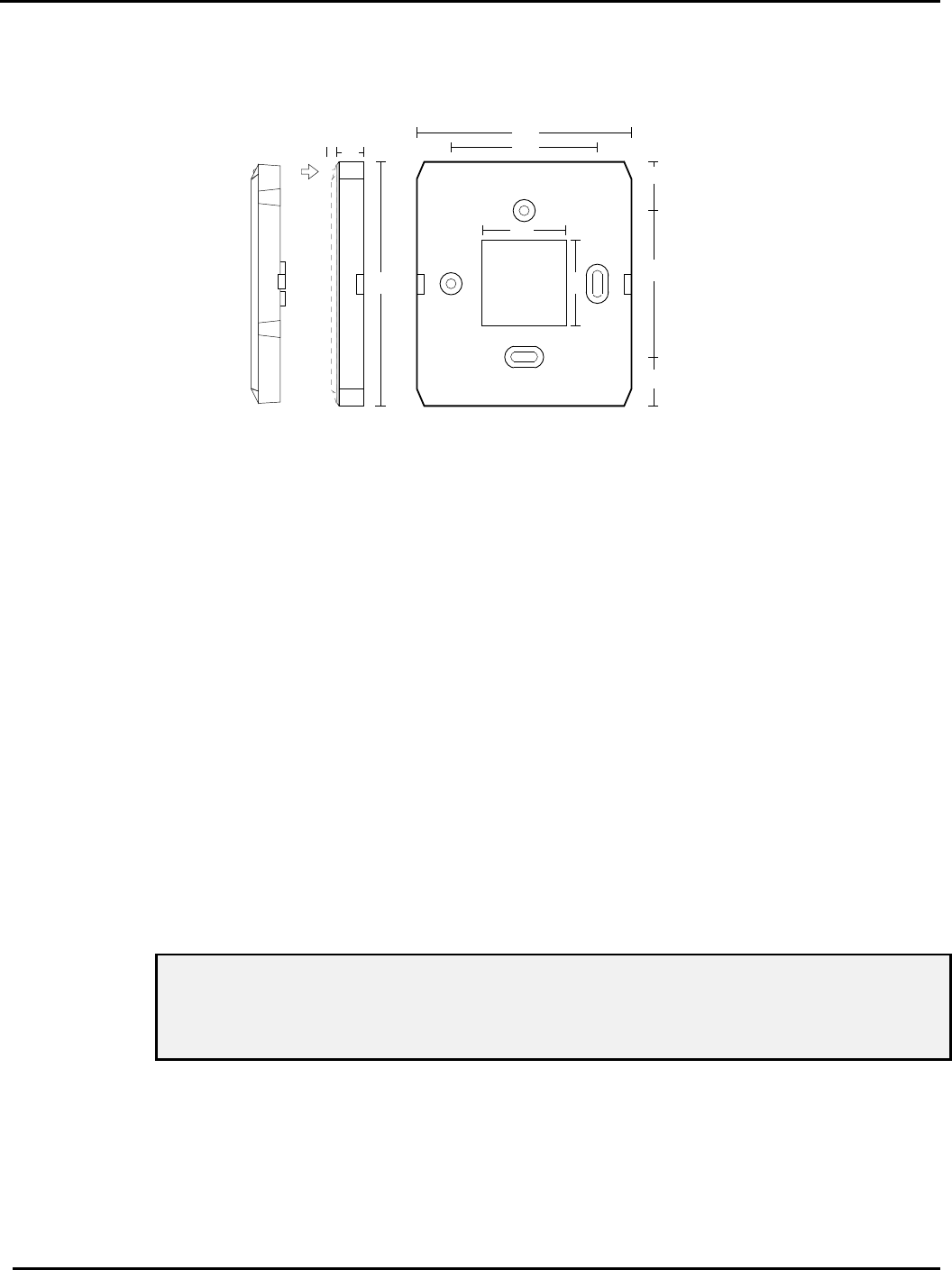
Mounting the Reader
This reader comes in two parts, the reader itself with flying lead, and a backplate.
1. The wiring harness should be routed through the aperture in the backplate.
2. Attach the backplate to a flat surface using #6 screws - or a mounting screw suitable for the
material to which the reader is being mounted. The two holes are 2.4 inches apart. Use the
top (round) hole first, and the lower (oval) hole to ensure the reader is straight.
3. Push the reader, with the green LED to the top, onto the backplate, the locking tabs on each
side should snap into place.
Removing the Reader
The reader can be removed from the backplate by placing a small flat-bladed screwdriver into the
apertures on each side of the backplate. Take care not to damage the reader or backplate.
Reader Operation
Normal Operation and LED Control
The reader LED will normally be red when the door or system is in the closed condition. When a
card is presented within range of the reader the code in the card will be read and the coding sent
to the controlling unit. If the card is valid for that door or system at that time the LED will go green
which is controlled by the N.O. relay or LED connection of the Control Panel. The LED will stay
green while the Brown LED wire is shorted to Common.
WARNING: For Output formats other than PAC, the output format of the reader will be
reprogrammed for a PAC system if the White and Brown wires are shorted and power is
applied to the reader. The reader will need to be sent in for repair to have the output format
reset once this has occurred.
Tamper Operation
The Blue wire tamper connection is a normally closed circuit between the blue wire and black wire
common connection. If the cable is cut this connection will go to an open circuit which can be used
to indicate a tamper violation condition.
3.94
0.4
2.36
3.46
0.79
0.79
0.16 2.36
1.38
1.38

Draft 1 20441 Operation and Installation Instructions © 1999
Page 5
Specification
Dimensions 3.46in x 3.94in x 0.56in
Voltage 10.5v DC to 20v DC
(supplied by Door Controller, Wiegand Interface or Control Panel)
Current Idle: 75-85mA
Reading: 75-85mA
Temperature: Operating -10C to +55C (14ºF to 130ºF)
Storage -30C to +80C (-20ºF to 175ºF)
Humidity: Operating 0-90% RH at 30C ±2C (85ºF±5ºF) for 24 hours
Reading Range: 0-4 inches
Lead Length: 36 inches
This device complies with part 15 of the FCC rules. Operation is subject to the following two conditions (1) this
device may not cause harmful interference, and (2) this device must accept any interference received, including
interference that may cause undesired operation.
FCC ID OQL-PAC-LP