PANASONIC VCR Manual 97110121
User Manual: PANASONIC PANASONIC VCR Manual PANASONIC VCR Owner's Manual, PANASONIC VCR installation guides
Open the PDF directly: View PDF ![]() .
.
Page Count: 48
THE QUALITY GOES IN BEFORE TI--IENAME GOES ON®
iAviso para nuestros
clientes de habla hispana:
consulte la informaci6n que
aparece al final de este manual!
Projection Color TV •
MTS Stereo Audio"
Surround Sound
Closed Captions
recycled paper
50 percent
Return the Product Registration
Card, and your TV could be free!
WARNING: TO REDUCE THE RISK OF ELECTRIC SHOCK DO NOT
REMOVE COVER (OR BACK). NO USER SERVICEABLE
PARTS INSIDE. REFER TO QUALIFIED SERVICE
PERSONNEL.
TO PREVENT FIRE OR SHOCK HAZARDS, DO NOT FXPOSE
THIS PRODUCT TO RAIN OR MOISTURE.
The lighming flash with arrowhead symbol, within an ecluilateral
triangle, is intended to alert the user to the presence of uninsulated
"dangerous voltage" within the product's enclosure that may be of
sufficient magnitude to constitute a risk of electric shock to persons.
_]k The exclamation point within an equilateral triangle is intended to
alert the user to the presence of important operating and maintenance
(servicing) instructions in the literature accornpanying the appliance.
Safety Tips
Refer to the "Safety Tips" booklet that came with your
product for important safety considerations.
Note to Cable TV S,tstem Installer
This reminder is provided t_ call the cable TV system
installer's attention to Article 820-40 of the NEC that
provides guidelines for prol_er grounding and, in particular,
specifies that the cable gJ'onnd shall be connected to the
grounding system of the building, as close to the point of
the cable entry as practical.
Power-Cord Polarization
This product is equipped with a polarized alternating-
current line plug (a plug having one blade wider than the
other.) This plug will fit into the power outlet only one
way. This is a safety feature. If you are unable to insert the
plug fully into the outlet, try reversing the plug. If the plug
should still fai! to fit, contact your electrician to replace
you!; obsolete outlet. Do not defeat the safety purpose of
the polarized plug.
CAUTION
To prevent electric shock, match wide blade of plug to
wide slot, fully insert.
ATTENTION
Pour _viter les chocs dlectriques, introduire la lame la plus
large de la fiche dans la iao:ne correspondante de la prise et
pousser jusqu'au fond.
Copyright © Zenith Electronics Corporation 1994 rVWAm,'2
CONTENTS
INTRODUCTION
'Welcome ......................................... ii
][nstallation Considerations ........................... ii
CONNECTIONS FOR YOUR TV
]Locations of User Items ............................. I- 1
Connection Center on Back of TV .................... 1-2
Other AiV Jacks on TV ............................. 1-2
Step 1. Make Basic Connection to TV ................. 1-3
Step 2. Make VCR Connections to TV ................. 1-4
Step 3. Make Super-VHS VCR Connections to TV ....... I-5
Step 4. Make A/V Connections to Auxiliary
A/V Jacks (VIDEO 3 IN or S-VIDEO 2 IN) .......... I-5
Step 5. Make Connections to Monitor Out Jacks ......... 1-5
Step 6. Make Surround Sound Connections to TV ........ 1-6
Step 7. Make External Speaker Connections to TV ....... 1-6
Step 8. Make Audio Connection to Stereo Amplifier ...... 1-7
THE FIRST TIME YOU OPERATE YOUR TV
Step 1. Connect the Power ........................... 2-1
Step 2. Select Your Viewing Source ................... 2-1
Step 3. Use Auto Program ........................... 2-1
Step 4. Time Functions ............................. 2-1
Step 5. Use Other Options ........................... 2-2
REMOTE CONTROL MODEL SC3820
"FV Operations .................................... 3-1
VCR Operations .................................. 3-2
TV and VCR Operational Notes ...................... 3-3
Preparation for Use ................................ 3-3
Installing Batteries ................................. 3-3
REMOTE CONTROL MODEL MBR3430
Operation ........................................ 4-1
Choose the Operating Mode ......................... 4-1
TV Operations .................................... 4-2
VCR Operations .................................. 4-3
Cable-TV Operations ............................... 4-4
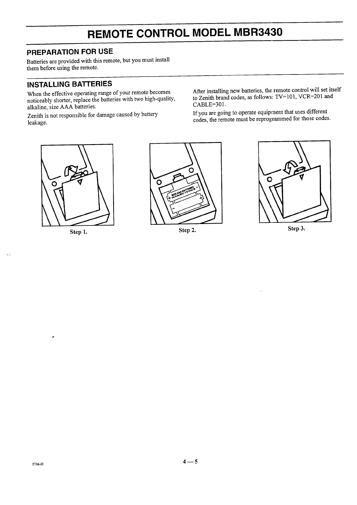
Preparation for Use ................................ 4-5
Installing Batteries ................................. 4-5
Programming Brand Codes .......................... 4-6
TV, VCR and Cable-TV Operating Codes .............. 4-7
QUICK REFERENCE TO ON-SCREEN MENUS
Available Menus .................................. 5-1
Summary of Menu Items ............................ 5-1
Menu Operation Example ........................... 5-3
SOURCE MENU
Source Selection .................................. 6-1
Source Identification ............................... 6-1
SETUP MENU
Auto Program .................................... 7-1
Ch. Add/Del ....................................... 7-1
Ch. Labels ....................................... 7-2
Tuning Band ..................................... 7-3
Auto Tuning ...................................... 7-3
Source ID ........................................ 7-3
Clock Set ......................................... 7-4
CaptiOns .......................................... 7-4
Projo Setup ....................................... 7-5
AUDIO MENU
Bass ............................................. 8-1
Treble ............................................ 8-1
Balance .......................................... 8-1
Audio ............................................ 8-1
SEQ ............................................. 8-1
Surround ......................................... 8-1
VIDEO MENU
Contrast .......................................... 9-1
Brightness ........................................ 9-1
Color ........................................... 9-1
Tint ............................................. 9-1
Sharpness ........................................ 9-1
Color Temp ...................................... 9-1
Video Filter ...................................... 9-1
Auto Flesh ....................................... 9-1
Picture Pref ...................................... 9-I
PIP MENU
Ch. Guide ....................................... 10-1
Ch. Review ..................................... 10-2
PIP Source ...................................... 10-2
PIP Color ...................................... 10-3
PIP Tint ......................................... 10-3
PIP Size ....................................... 10-3
PIP OPERATION AND COI_NECTIONS
PIP Overview ..................................... 11-I
Typical Connections ............................... 11-1
How to Select Main Picture & PIP Source ............. 1I-3
PIP Functions ................................... 11-4
MAINTENANCE AND TRO1LJBLESHOOTING
Caring for Your TV ................................ 12-1
Extended Absence ................................ 12-1
TV Picture Interference ............................ 12-I
Before Calling for Service .......................... 12-2
Product Registration Card
Recommended Accessories For Your TelevMon
Aviso para nuestros clientes de habla hispanLa
Your Zenith Warranty
HOW TO USE YOUR OPERATING GUIDE
THIS OPERATING GUIDE DESCRIBES A FAMILY OF TV MODELS. SOME MODELS tIAVE FEATURES THAT ARE
NOT PROVIDED ON OTHER MODELS, SUCH AS AUXILIARY JACKS OR TWO REMOTE CONTROLS. DIFFERENT
CONTROL PANELS AND REMOTE CONTROLS MAY BE USED FROM MODEL-TO-MODEL. REFER TO THE APPLI-
CABLE SECTIONS OF THIS OPERATING GUIDE FOR THE FEATURES AND ITEMS PROV [DED WITH YOUR TV.
,n*-o i
INTRODUCTION
WELCOME
Welcome into the family of Zenith Color Television owners.
This guide provides instructions on how to operate your new
TV. It is supplemented by a booklet containing Safety Tips.
We urge you to read these publications carefully so that you
will receive full enjoyment from your new Zenith TV for
many years to come.
Your new Zenith projection TV has been designed and built to
give you the very best in quality, features and performance.
There are many regional Zenith distributors and thousands of
distributor-approved Zenith service centers throughout the
U.S., Canada and Mexico who can attend promptly and effec-
tively to ordinary service needs.
If you should have an unusual performance or service problem
that cannot be satisfactorily resolved by your distributor-
approved Zenith service center, contact the regional Zenith dis-
tributor in your area, or write:
Zenith Electronics Corporation
Customer Servi,:zeDepartment
1000 Milwaukee Avenue
Glenview, IL 6(1625-2493
Telephone: (847) 391-8752
Mon-Fri, 8:00 a.m. - 4:30 p.m. Central Time
Send the model number, serial number, and date of purchase
or original installation, with a full explanation of the problem
and the service history. We will welcome,, the opportunity to
look into your specific question or problem and to be of assis-
tance in resolving it promptly.
The model and serial numbers of your new TV are located on the
back of the TV cabinet. For your future convenience and protec-
tion, we suggest that you recorJ these numbers here:
Model No.
Serial No.
INSTALLATION CONSIDERATIONS
Before you install your TV...
Ventilation -- Proper ventilation keeps your TV
running cool. Air circulates through perforations
in the back and bottom of the cabinet. Do not
block these vents or you will shorten the life of
your TV.
_.iPower Source Your TV is designed to
operate
u
on normal household current, 120 volt 60 Hertz AC.
Do not attempt to operate it on DC current.
Power Cord -- Your power cord has a polarized
plug as required by Underwriters' Laboratories. It
has one regular blade and one wide blade and fits
only one way into a standard electrical outlet. If
the blades will not enter either way, your outlet is
very old and non-standard. A new outlet should be
installed by a qualified electrician.
Safe Operation -- Your TV is manufactured and
tested with your safety in mind. However, unusual
stress caused by dropping or mishandling, expo-
sure to flood, fire, rain or moisture, or accidental
spilling of liquids into the TV, can result in poten-
tial electrical shock or fire hazards. If this hap-
pens, have your TV checked by a service
technicmn before using it again.
Please read and observe each safety point in the "Safety
Tips" folder when installing and using your TV.
VIDEO GAMES AND OTIIER FIXED
PATTERN DISPLAY CAUTION -- I5you use your TV for
video games, teletext or othm fixed displays, avoid setting the
BRIGHTNESS control for at, excessively bright picture. A
bright, fixed pattern, if used for long periods of time, can re-
sult in a permanent imprint on the TV picture tube. You can re-
duce this possibility by alternating the use of the fixed pattern
display with normal TV picture viewing, by turning down the
CONTRAST control for sustained fixed pattern use, and by
turning oft the fixed pattern display when nol in use.
PLUGGING IN YOUR 'rv -- Be sure to plug your TV into
an "unswitched" AC power source. The "switched" AC out-
lets found on some video ,equipment will not continue supply-
ing power to the TV once the equipment is turned off. If the
power to the TV is interrupted, you will have to reset the clock
in the TV to the current time.
PICTURE SCREEN CLEANING -- Use a soft cloth mois-
tened with warm water and rub lightly in the soiled areas of
the screen. DO NOT USE A FISSUE OP, PAPER TOWEL,
AS THESE MAY DAMAGE SURFACE. Wipe only in the
vertical (up/down) direction (along the grooves). If there is a
dirt buildup, a mild solution of warm wa:er and Ivory dish-
washing detergent may be:used. Use dr), soft cloth to dry the
screen. Care should be taken to avoid scratches or damage to
the screen surface.
NOTE -- The TV screen is easily damaged. Avoid acciden-
tal contact with the screen.
TVWEPRO3 ii
CONNECTIONS FOR YOUR TV
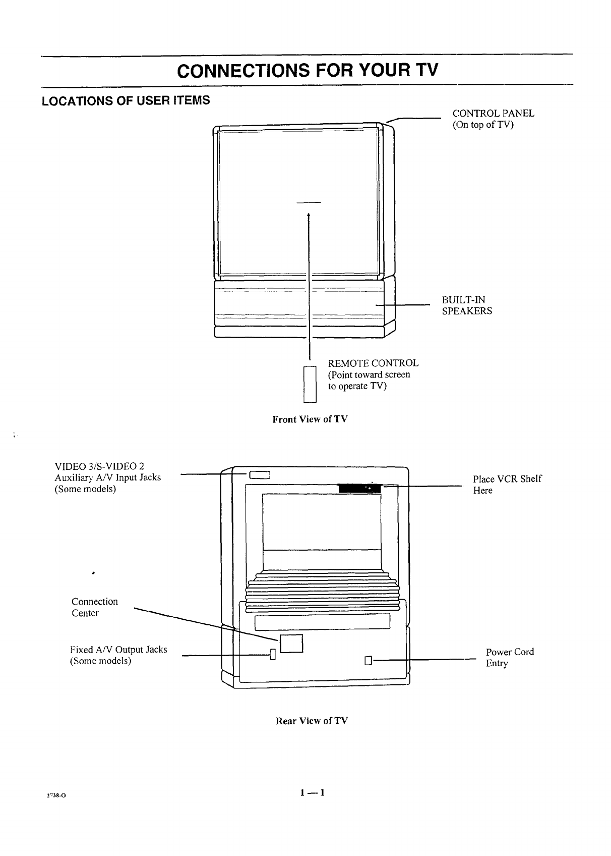
LOCATIONS OF USER ITEMS
f
I
REMOTE CONTROL
(Point toward screen
to operate TV)
Front View of TV
CONTROL ]?ANEL
(On top ofT'V)
BUILT-IN
SPEAKERS
VIDEO 3/S-VIDEO 2
Auxiliary A/V Input Jacks
(Some models)
Connection
Center
Fixed A/V Output Jacks
(Some models) []
Place VCR Shelf
Here
Power Cord
Entry
Rear View of TV
r,3s-o 1_1
CONNECTIONS FOR YOUR TV
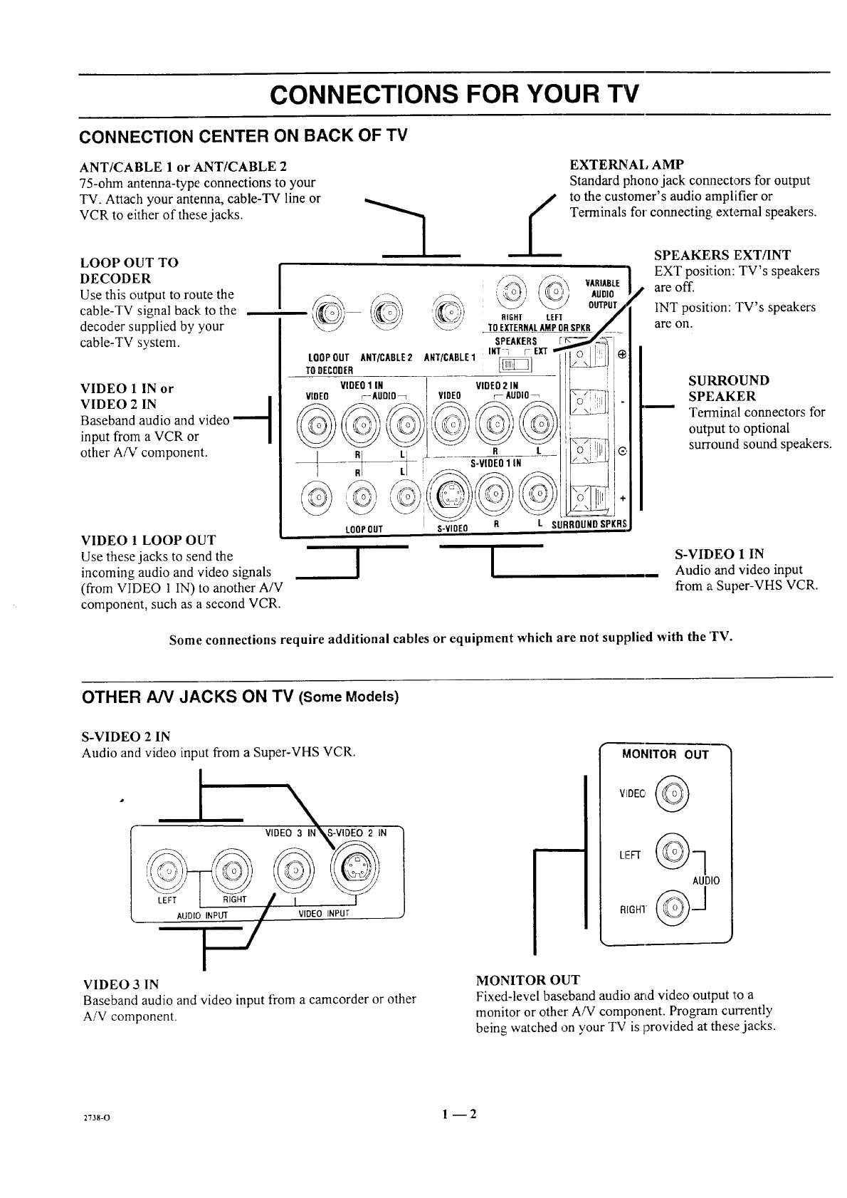
CONNECTION CENTER ON BACK OF TV
ANT/CABLE 1 or ANT/CABLE 2
75-ohm antenna-type connections to your
TV. Attach your antenna, cable-TV line or
VCR to either of these jacks.
LOOP OUT TO
DECODER
Use this output to route the
cable-TV signal back: to the
decoder supplied by :your
cable-TV system.
I
VIDEO 1 IN or
VIDEO 2IN l
Baseband audio and video --1
input from aVCR or
other A/V component.
VIDEO 1LOOP OUT
Use these jacks to send the
incoming audio and 'video signals
(from VIDEO 1 IN) to another A/V
component, such as a second VCR.
LOOPOUT ANT/CABLE2
TODECODER
VIDEO1 IN
VIDEO r_AUDIO_
RI LI
LOOP OUT
A[qT/CABLE1 _]
VIDEO2 IN
VIDEO r- AUDIO
EXTERNAl, AMP
Standard phoao jack cormectors for output
to the customer's audio amplifier or
Terminals for connecting: external speakers.
,/_,.S._, VARIABLE_i'ic 1
,_, AUDIO
OUTPUT
RIGHT LEFT
TOEXTERNALAMPORSPKR
SPEAKERS
INT _[- EXT
R L
S-VIDEO1 IN
LSURROUNDSPKRS
!
S-VIOEO R
!
SPEAKERS EXT/INT
EXT position: TV's speakers
are off.
INT position: TV's speakers
are on.
SUIGROUND
SPEAKER
Terminal connectors for
output to optional
surround sound speakers.
S-VIDEO 1 IN
Audio and video input
from a Super-VHS VCR.
Some connections require additional cables or equipment which are not supplied with the TV.
OTHER A/V JACKS ON TV (Some Models)
S-VIDEO 2 IN
Audio and video input from a Super-VHS VCR.
IVIDEO 3I_N S-VIDEO 2IN
,-
AUDIO INPUT VIDEO INPUT
MONITOR OUT
AUDIO
VIDEO 3 IN
Baseband audio and video input from a camcorder or other
A/V component.
MONITOR OUT
Fixed-level baseband audio arid video output 1:0 a
monitor or other A/V component. Program currently
being watched on your TV is provided at these jacks.
2738-o 1 -- 2
CONNECTIONS FOR YOUR TV
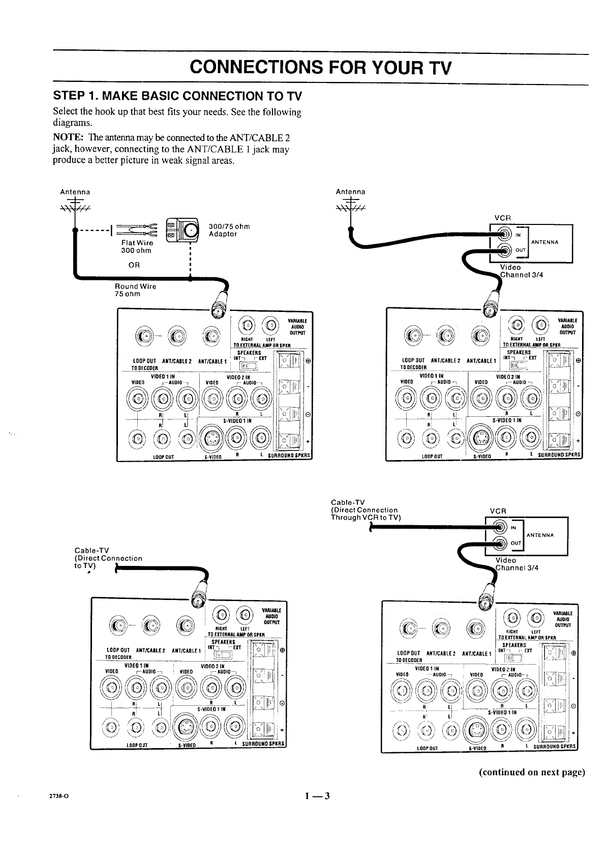
STEP 1. MAKE BASIC CONNECTION TO TV
Select the hook up that best fits your needs. See the following
diagrams.
NOTE: The antenna may be connected to the ANT/CABLE 2
jack, however, connecting to the ANT/CABLE 1jack may
produce a better picture in weak signal areas.
Antenna
...... I__ _
Flat Wire
300 ohm ,,
OR |
i
Round Wire
75 ohm
300/75 ohm
Adaptor
J
_--_ _ VARIABLE
AUOlO
OUTPb'T
RIGHT LEFT
TO EXTERNAl_AMP ORgPKR
SPEAKERS
L00P0uTA.t/cAsLE2AWTIcxsLel'_mtr_eXT Il'o'll!Nle
viDeo1IN video2iN / !
VIDEO r--AUDIO_ VIDEO ;- AUOlO-_ I I r_ I_Tl
'L,%_!'"
LOOP OUT S-VIDEO R L SURROUND SPI(RS
Antenna
VCR
t __'=-'__b '7"1ANtE"N'I
I ,"_k outl I
Ghannel 3/4
_-',_ :x, vAR_,_
r_o] ( {I o I I AUOlO
_ _ [TO EXTERIqALAMp OR SPIR
LQOPOUTANT/CABLE2lUtt/cXetE1im_/_ exT II'o'l II I_
TOUE_OOER__ ___ I _,. i,_tI
VIDEO1in vineo2m i ! i I
YiOE0 mAUDIO-1 VIDEO r--AOel[I-_ I I_ll.
/ R LI _r___ L_i I.o. I1'_1®
--_ -_ -- _S-VIDEO1 IN I _
LOOP OUT S-VIQEO BtSURROUNO SPIll
Cable-TV
(Direct Connection
toTV)•
Cable-TV
(Direct Connection
Through VCR to TV) VCR
I 'q ANTENNA
I
Video 3/4
LOOP OUT ANT/CA61_E2 ANT/CABLE 1
TODECQDER
VIDEOllN VIDEO21N
VIDEO -AUOlO_ iVIDEO r- AUDIO-q
iAUDIO
OUTPUT
RIGHT LEFT
TOEI[TERNAI. lIMP OR IPKR
SPEAKER!I
iNT"'1 r EXT
LOOPOUI S-VIDEO L SURROUND SPKRS
(continued on next page)
2Tas-o 1-- 3
CONNECTIONS FOR YOUR TV
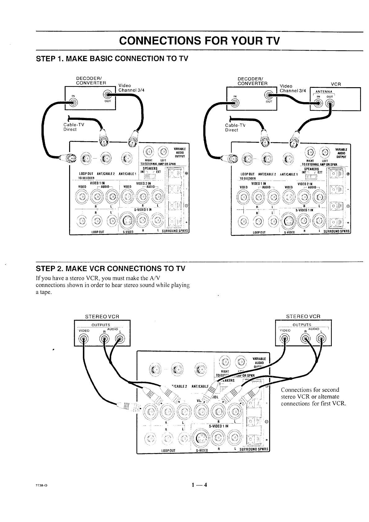
STEP 1. MAKE; BASIC CONNECTION TO TV
LOOPOUT L SURROUND SPKRS
Cable-TV
Direct
I
DECODER/
CONVERTER "1 Video tVCR
._-_ /Channel 3/4 I ANTENNA
'" r-i_'
'i_Sa';', ,'_" / 7 =o,o
OUTPI/T
i_ 'TO E[IERI4AL.IMP OR SPill
SPEAKERS
LQOPOUT AHT/CABLI!2 J'_NT/CADLE1 INT_ rE),'T
TODECOOER _
VIDEO 1 IN VIOEO 2 !IN
VIDEO r AUDIO _VIDEO _AUDIO_
LOOPOUT S-VIDEO
STEP 2. MAKE VCR CONNECTIONS TO TV
If'you have a stereo VCR, you must make the A/V
connections shown in order to hear stereo sound while playing
a tape.
STEREO VCR
OUTPUTS
VIDEO R AUDIO L
STEREO VCR
OUTPUTS 3_05_o
\'IDEO R L
I
' R Li
RLI
LOOPOUT
ANT/CABLE.
/
q
VluL;,
RIGH'[
S-VIDEO 1 IN
i,
C i ili
S-VIDEO R L SU£BOUNDSPKR
Connections for second
stereo VCR or alternate
connections for first VCR.
?738-0 l --4
CONNECTIONS FOR YOUR TV
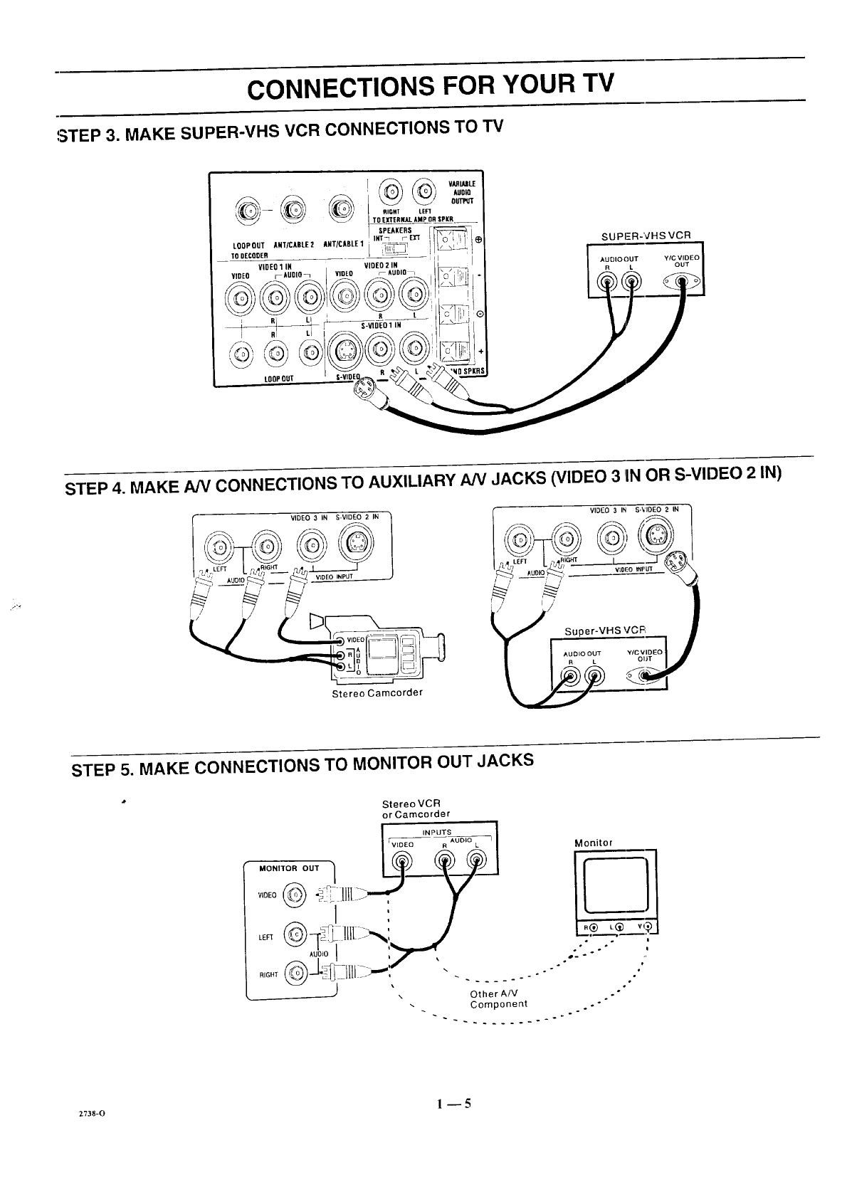
STEP 3. MAKE SUPER-VHS VCR CONNECTIONS TO TV
SUPER-VHS VCR
STEP 4. MAKE NV CONNECTIONS TO AUXILIARY NV JACKS (VIDEO 3 1INOR S-VIDEO 2 IN)
Stereo Camcorder
VIDEO 3IN S-'¢IOEO 2IN
.../' Super-VHS V'CFI
STEP 5. MAKE CONNECTIONS TO MONITOR OUT JACKS
StereoVCR
or Camcorder
INPUTS
Wr_EeOEe _uo_o L7Monitor
_1 ./-,
,oD,oI ,,_,-,,r
RIGHT _-J___ !_ Jill jm,-, . .... .. "
2738-0 1_5
CONNECTIONS FOR YOUR TV
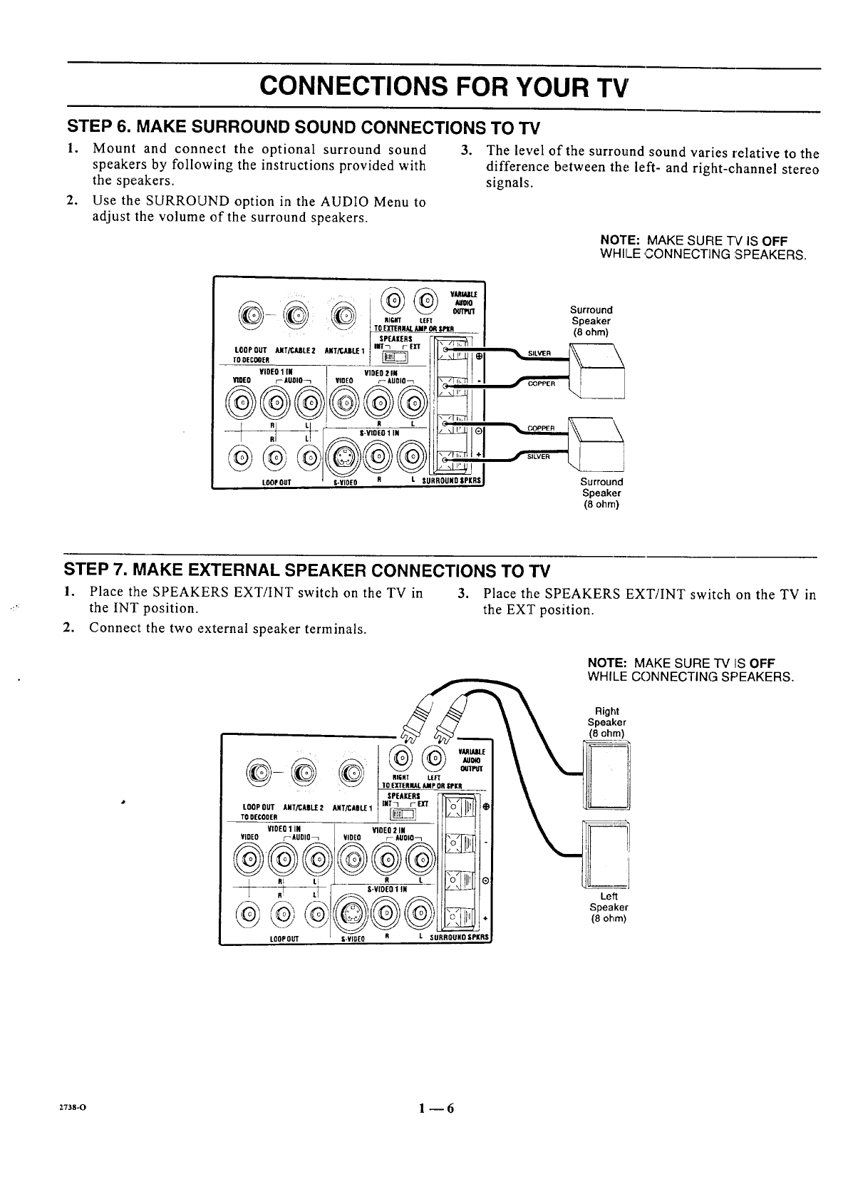
STEP 6. MAKE SURROUND SOUND CONNECTIONS TO TV
1. Mount and connect the optional surround sound
speakers by following the instructions provided with
the speakers.
2. Use the SURROUND option in the AUDIO Menu to
adjust the volume of the surround speakers.
,The level of the surround sound varies relative to the
difference between the left- and right-channel stereo
signals.
NOTE: MAKE SUFIE 7V IS OFF
WHILE ,CONNECTING :SPEAKERS.
i AUD_
_ _ T_O EXTEflZ_r. AIIp O_ SPtA
I SPEAIERS [-P::_:_::::_:::_::;(7
LOOPOUT_rX_tEZ A,T_JUlt.E1inrrr_ m" ILK;":,:",:,.
rD.c00,, __ t _ I1_ I_1
¥iDEOIIN I mEOZ" Eli___II I
HOED r-igoIo_ VIDEO r- AUDIO_ J I I\_/] _ [ "I
I
LOOPOUT S-VIDEO SURR RSI
Surround
Speaker
(8 ohm}
Surround
Speaker
(8 ohm)
STEP 7. MAKE EXTERNAL SPEAKER CONNECTIONS TO TV
1. Place the SPEAKERS EXT/INT switch on the TV in 3. Place the SPEAKERS EXT/INT switch on the TV in
the INT position, the EXT position.
2. Connect the two external speaker terminals.
NOTE: MAKE SURE TV IS OFF
WHILE CONNECTING SPEAKERS.
@@@
SPEAKERS
LOOP OUT ANTiCASII:2 ANT/CABLE1 INT7 r- E]rT
TO DECODER
VIDEO 1 IN VIDEO 2 IN
VIDEO ;_AUDIO_ VIDEO r_ AUDIO_
At ti R I.
.!
LOOP OUT
TO EXTERNAl. AMP OR SrKR
S'VIOE01 IN _(_
\.,"
@#®
I(RSI-VIDE0 SURR U
Right
Speaker
(8 ohm)
Left
Speaker
{8 ohm)
+73s-o 1--6
CONNECTIONS FOR YOUR TV
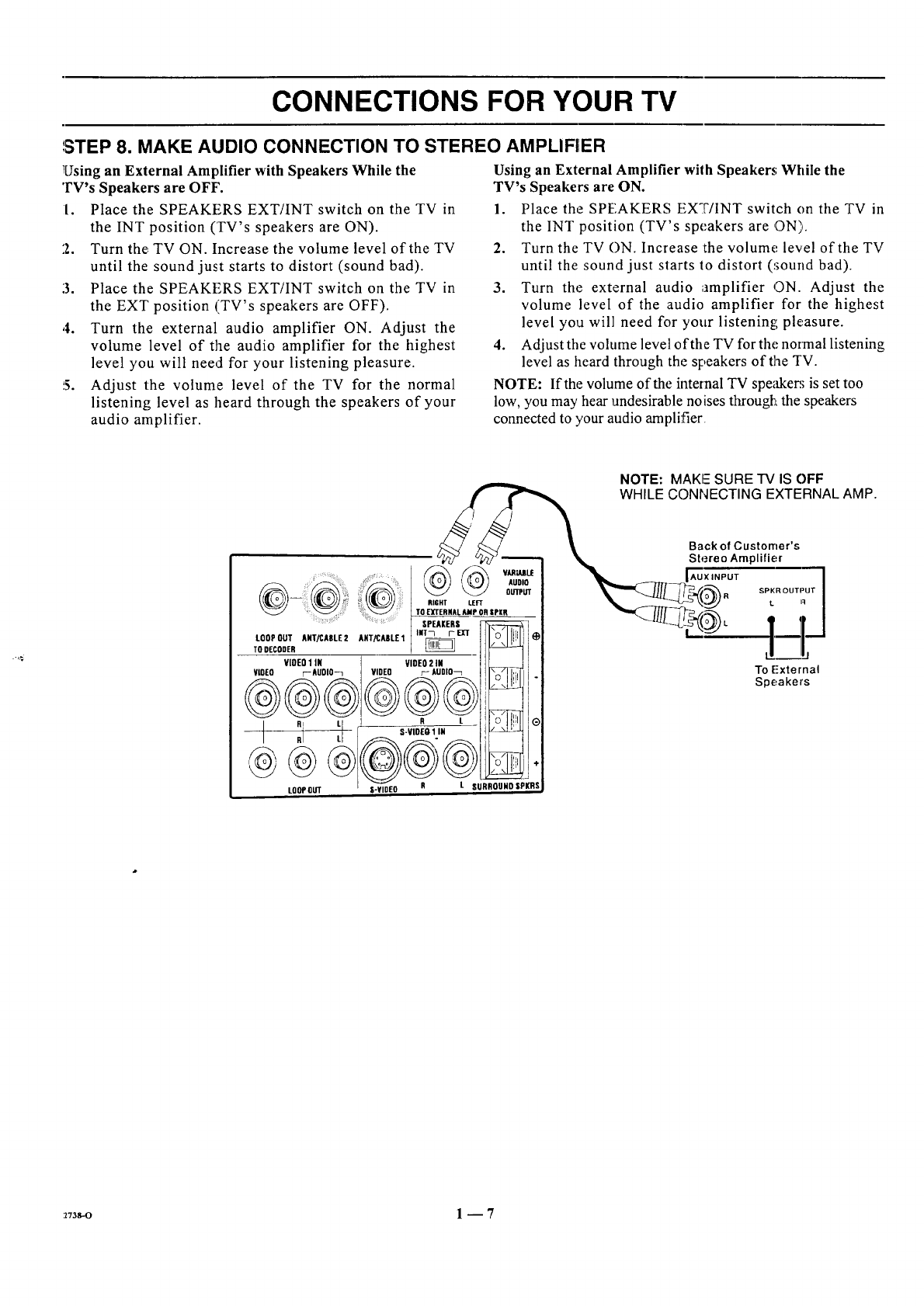
',STEP 8. MAKE AUDIO CONNECTION TO STEREO AMPLIFIER
Using an External Amplifier with Speakers While the
TV's Speakers are OFF'.
I. Place the SPEAKERS EXT/INT switch on the TV in
the INT position (TV's speakers are ON).
2. Turn the TV ON. Increase the volume level of the TV
until the sound just starts to distort (sound bad).
3. Place the SPEAKERS EXT/INT switch on the TV in
the EXT position (TV's speakers are OFF).
,4. Turn the external audio amplifier ON. Adjust the
volume level of the audio amplifier for the highest
level you will need for your listening pleasure.
5. Adjust the volume level of the TV for the normal
listening level as heard through the speakers of your
audio amplifier.
Using an External Amplifier with Speakers; While the
TV's Speakers are ON.
1. Place the SPEAKERS EXT/INT switch on the TV in
the INT position (TV's speakers are ON).
2. Turn the TV ON. Increase :the volume+ level of the TV
until the sound just starts to distort (_;ound bad).
3. Turn the external audio amplifier ON. Adjust the
volume level of the audio amplifier for the highest
level you will need for your listening pleasure.
4. Adjust the volume level of the TV for the normal listening
level as heard through the speakers of the TV.
NOTE: If the volume of the internal TV speaker; is set too
low, you may hear undesirable noises througl_Lthe speakers
connected to your audio amplifier
NOTE: MAKE SURE "IV IS OFF
WHILE CONNECTING EXTERNAL AMP.
.......@ + +
::: :' : TO EXTERNAL AMP OR SPI(R
SPEAKERS F_
ToLOOPDEcODEROUTANT/CABLE2 ANT/CABL£1INT_i- EX'T
VIOEO1 IN VIDEO2 iN
@_@__@_VlO[O F- AUDIO-1 VIDEO r- AUDIO_L _iO
RI IR
,I LL S-V|DEO 1 IN
LOOPOUT S-¥1DEO R
_VARiAJIL£
AUDIO
OUTPUT
÷
L SURROUHOSPKRS
Back of Customer's
Stereo Amplifier
'+++]lij
SPKR OUTPUT
L R
L,. _-=j
To External
Speakers
:z73s-o 1-- 7
THE FIRST TIME YOU OPERATE YOUR TV
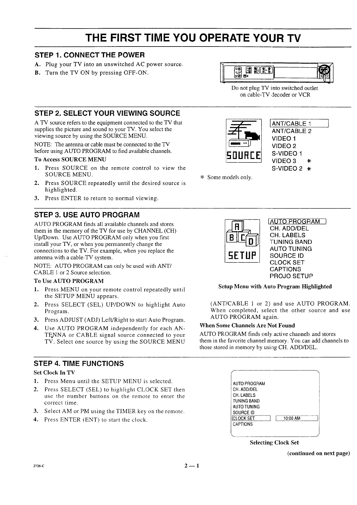
STEP 1. CONNECT THE POWER
A. Plug: your TV into an unswitched AC power source.
B. Turn the TV ON by pressing OFF-ON. !Do not plug TV into switched outlet
on cable-TV decoder or VCR
STEP 2. SELECT YOUR VIEWING SOURCE
A TV source refers to the equipment connected to the TV that
supplies the picture and sound to your "IV. You select the
viewing source by using the SOURCE MENU.
NOTE: The antenna or cable must be connected to the TV
before using AUTO PROGRAM to find available channels.
To Access SOURCE MENU
1. Press SOURCE on the remote control to view the
SOURCE MENU.
2. Press SOURCE repeatedly until the desired source is
highlighted.
3. Press ENTER to return to normal viewing.
c;DUREE
* Some models only.
[ANT/CABLE "1
ANT/CABLE 2
VIDEO 1
VIDEO 2
S-VIDEO 1
VIDEO 3 -_,_
S-VIDEO 2-x'-
STEP 3. USE AUTO PROGRAM
AUTO PROGRAM finds all available channels and stores
them in the memory of the TV for use by CHANNEL (CH)
Up/Down. Use AUTO PROGRAM only when you first
install your TV, or when you permanently change the
connections to the "FV. For example, when you replace the
antenna with a cable--TV system.
NOTE: AUTO PROGRAM can only be used with ANT/
CABLE 1 or 2 Source selection.
To Use AUTO PROGRAM
1. Press MENU on your remote control repeatedly until
the SETUP MENU appears.
2. Press SELECT (SEL) UP/DOWN to highlight Auto
Program.
3. Press ADJUST (ADJ) Left/Right to start Auto Program.
4. Use AUTO PROGRAM independently for each AN-
TE.NNA or CABLE signal source connected to your
TV. Select one source by using the SOURCE MENU
5ETIJP
EAUTO PROGFIAM J
CH. ADD/DEL
CH. LABELS
I-UNING BAND
AUTO TUNING
SOURCE ID
(;LOCK SET
CAPTIONS
PROJO SETUIP
Setup Menu with Auto Program Hi_,hlighted
(ANT/CABLE 1 or 2) and use AUTO PROGRAM.
When completed, select the other source and use
AUTO PROGRAM again.
When Some Channels Are Not Found
AUTO PROGRAM finds only active channels and stores
them in the favorite channel memory. You can add channels to
those stored in memory by using CH. ADD/DEE
STEP 4. TIME FUNCTIONS
Set Clock In TV
1. Press Menu until the SETUP MENU is selected.
2. Press SELECT (SEL) to highlight CLOCK SET then
use the number buttons on the remote to enter the
correct time.
3. Select AM or PM using the TIMER key on the remote.
4. Press ENTER (ENT) to start the clock.
S
IAUTOPROGRAM
ICH.ADD/DEL
CH.LABELS
TUNINGBAND
AUTOTUNING
SOURCEID
CLOCKSET
CAPTIONS ][10:00AIVI
Selecting Clock Set
(continued on next page)
2738-C 2- 1
THE FIRST TIME YOU OPERATE YOUR TV
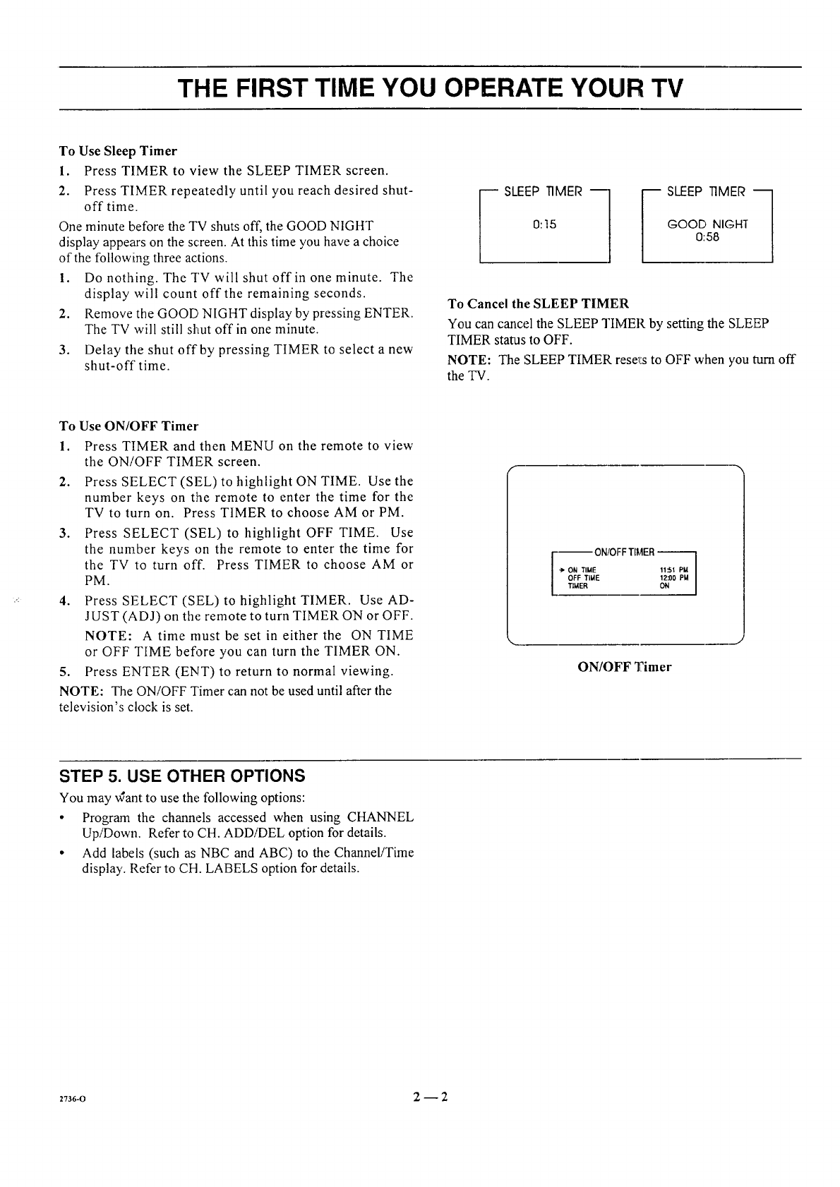
To Use Sleep Timer
1. Press TIMER to view the SLEEP TIMER screen.
2. Press TIMER repeatedly until you reach desired shut-
offtime.
One minute before the TV shuts off, the GOOD NIGHT
display appears on the screen. At this time you have a choice
of the following three actions.
1. Do nothing. The TV will shut off in one minute. The
display will count off the remaining seconds.
2. Remove the GOOD NIGHT display by pressing ENTER.
The TV will still shut off in one minute.
3. Delay tile shut off by pressing TIMER to select a new
shut-off time.
_ SLEEP TIMER ---1
0:15
_ SLEEP TIMER ---1
GOOD NIGHT
0:58
To Cancel the SLEEP TIMER
You can cancel the SLEEP TIMER by setting the SLEEP
TIMER status to OFF.
NOTE: The SLEEP TIMER rese_i:sto OFF when you _rn off
the TV.
To Use ON/OFF Timer
1. Press TIMER and then MENU on the remote to view
the ON/OFF TIMER screen.
2. Press SELECT (SEL) to highlight ON TIME. Use the
number keys on the remote to enter the time for the
TV to turn on. Press TIMER to choose AM or PM.
3. Press SELECT (SEL) to highlight OFF TIME. Use
the number keys on the remote to enter the time for
the TV to turn off. Press TIMER to choose AM or
PM.
4. Press SELECT (SEL) to highlight TIMER. Use AD-
JUST (ADJ) on the remote to turn TIMER ON or OFF.
NOTE: A time must be set in either the ON TIME
or OFF TIME before you can turn the TIMER ON.
5. Press ENTER (ENT) to return to normal viewing.
NOTE: The ON/OFF Timer can not be used until after the
television's clock is set.
--- ON/OFF TI_,tER--
-> ON TIME 11::51 PM
OFF TIME 12:O0 PM
TIMER ON
ON/OFF Timer
STEP 5. USE OTHER OPTIONS
You may ,,Cant to use the following options:
• Program the channels accessed when using CHANNEL
Up/Down. Refer to CH. ADDiDEL option for details.
•Add labels (such as NBC and ABC) to the Channel/Time
display. Refer to CH. LABELS option for details.
27s6-o 2--2
REMOTE CONTROL MODEL SC3820
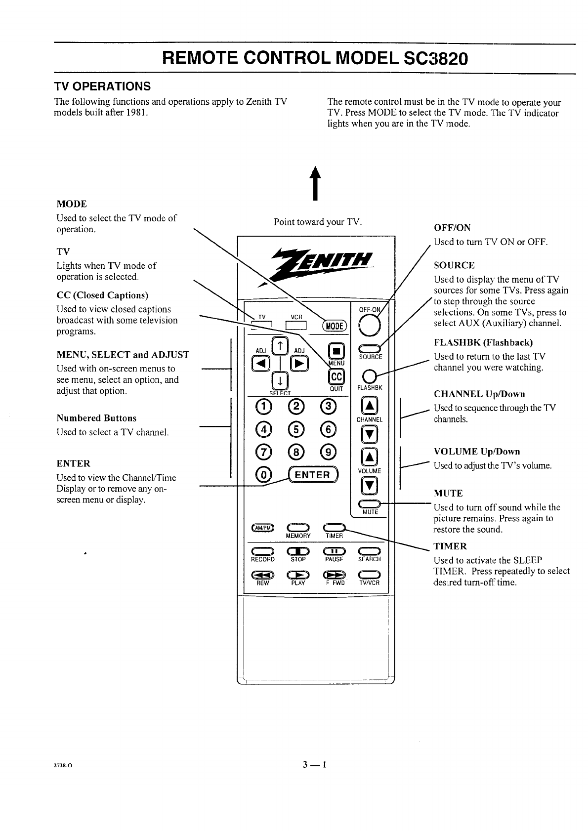
TV OPERATIONS
The following functions and operations apply to Zenith TV The remote control must be in the TV mode to operate your
models built after 1981. TV. Press MODE to select the TV mode. _,?heTV indicator
lights when you are in the TV mode.
MODE
Used to select the TV mode of
operation.
TV
Lights when TV mode of
operation is selected.
CC (Closed Captions)
Used to view closed captions
broadcast with some television
programs.
MENU, SELECT and ADJUST
Used with on-screen menus to
see menu, select an option, and
adjust that option.
Numbered Buttons
Used to select a TV channel.
ENTER
Used to view the Channel/Time
Display or to remove any on-
screen menu or display.
t
Point toward your TV.
® ® ®
®® ®
®® ®
OFF-ON/
E
MUTE
MEMORY
RECORD STOP PAUSE SEARCH
REW PLAY F FWD TVIVCR
/OFF/ON
Used to turn TV ON or OFF.
:SO URCE
Used to display the menu of TV
sources for some TVs. Press again
to step through the source
sek,ctions. On some TVs, press to
select AUX (Auxiliary) channel.
FLASHBK (Flashback)
Used to return 1:othe last TV
channel you were watching.
J
,CHANNEL Up/I)own
:Usedto sequence through the TV
charnels.
'VOLUME Up!Down
!Used to adjust the TV's volume.
MUTE
Used to turn off sound while the
picture remains. Press again to
restore the sound.
'rIMER
Used to activate the: SLEEP
TIMER. Press repeatedly to select
Jes:i,red turn-off time.I I
2738-O 3-- 1
REMOTE CONTROL MODEL SC3820
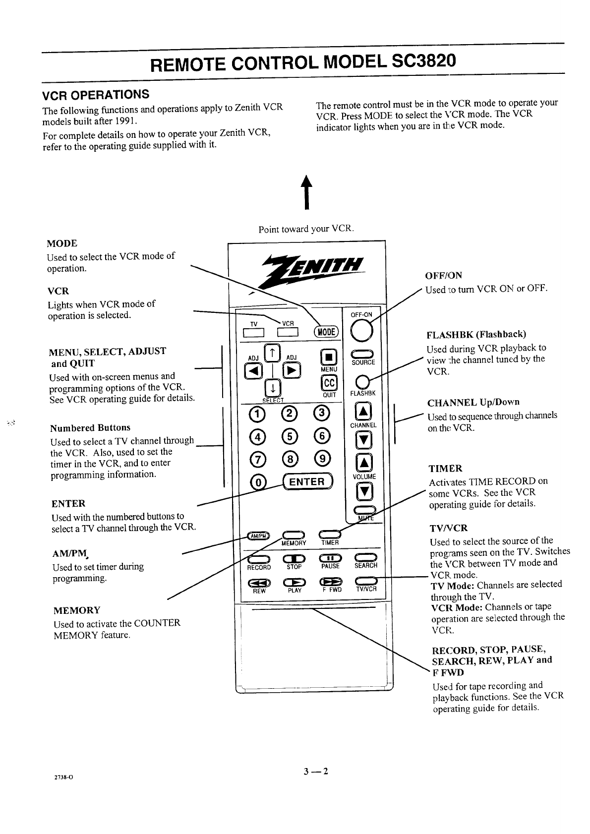
VCR OPERATIONS
The following functions and operations apply to Zenith VCR
models built after 1991.
For complete details on how to operate your Zenith VCR,
refer to the operating guide supplied with it.
The remote control must be in the VCR mode to operate your
VCR. Press MODE to select the VCR mode. The VCR
indicator lights when you are in tl:_,eVCR mode.
t
MODE
Used to select the VCR mode of
operation.
VCR
Lights when VCR mode of
operation is selected.
Point toward your VCR.
MENU, SELECT, ADJUST
and QUIT
Used with on-screen menus and
programming options of the VCR.
See VCR operating guide for details.
Numbered Buttons
Used to select a TV channel through
the VCR. Also, used to set the
timer in the VCR, and to enter
programming information.
ENTER
Used with the numbered buttons to
select a TV channel through the VCR.
Used to set timer during
programming.
MEMORY
Used to activate the COUNTER
MEMORY feature.
ADJ _ADJ _:_
N
QUIT
SELECT
®® ®
®®®
®®®
_._ENTER )
SOURCE
01
FLASHBK
IAI
CHANNEL
Ill
IAI
VOLUME
IV'l
RECORD STOP PAUSE SEARCH
CE) (EE) L..J
REW PLAY FFWD TVNDB
OFF/ON
J Used 'l:oturn VCR ON or OFF.
FLASHBK (Flashback)
Used during VCP playback to
J view :he channel tuned by the
VCR.
CHANNEL Up/Down
Used to sequence _arough channels
on the VCR.
TIM ER
Activates TIME RECORD on
some VCRs. See the: VCR
operating guide for details.
TV/VCR
Used to select the source of the
programs seen on the TV. Switches
the VCR between TV mode and
VCR mode.
TV lVlode: Channels are selected
through the TV.
VCR Mode: Channels or tape
operation are se:iected through the
VCP.
RECORD, STOP, PAUSE,
SEARCH, REW, PLAY and
FFWD
Used for tape recording and
playback functions. See the VCR
operating guide for details.
:Tss-o 3 -- 2
REMOTE CONTROL MODEL SC3820
TV AND VCR OPERATIONAL NOTES
Some controls on the remote, like PLAY and VOLUME will
always operate the VCR or the TV. Whether other keys
operate the TV or the VCR depends on the mode of the
remote control. For example, OFF-ON will turn the VCR ON
and OFF while the remote control is in the VCR mode. It will
turn the TV ON or OFF while the remote control is in the TV
mode.
Some of the functions provided by this remote control may
not be part of your TV and/or VCR. You wiill not be able to
activate those functions even though there is a control button
on the remote. For example, pressing TIMER provides direct
access to the Sleep Timer on many TVs. If your TV does not
have a Sleep Timer, pressing TIMER has no effect.
PREPARATION FOR USE
Batteries are provided with this remote, but you must install
them before using the remote.
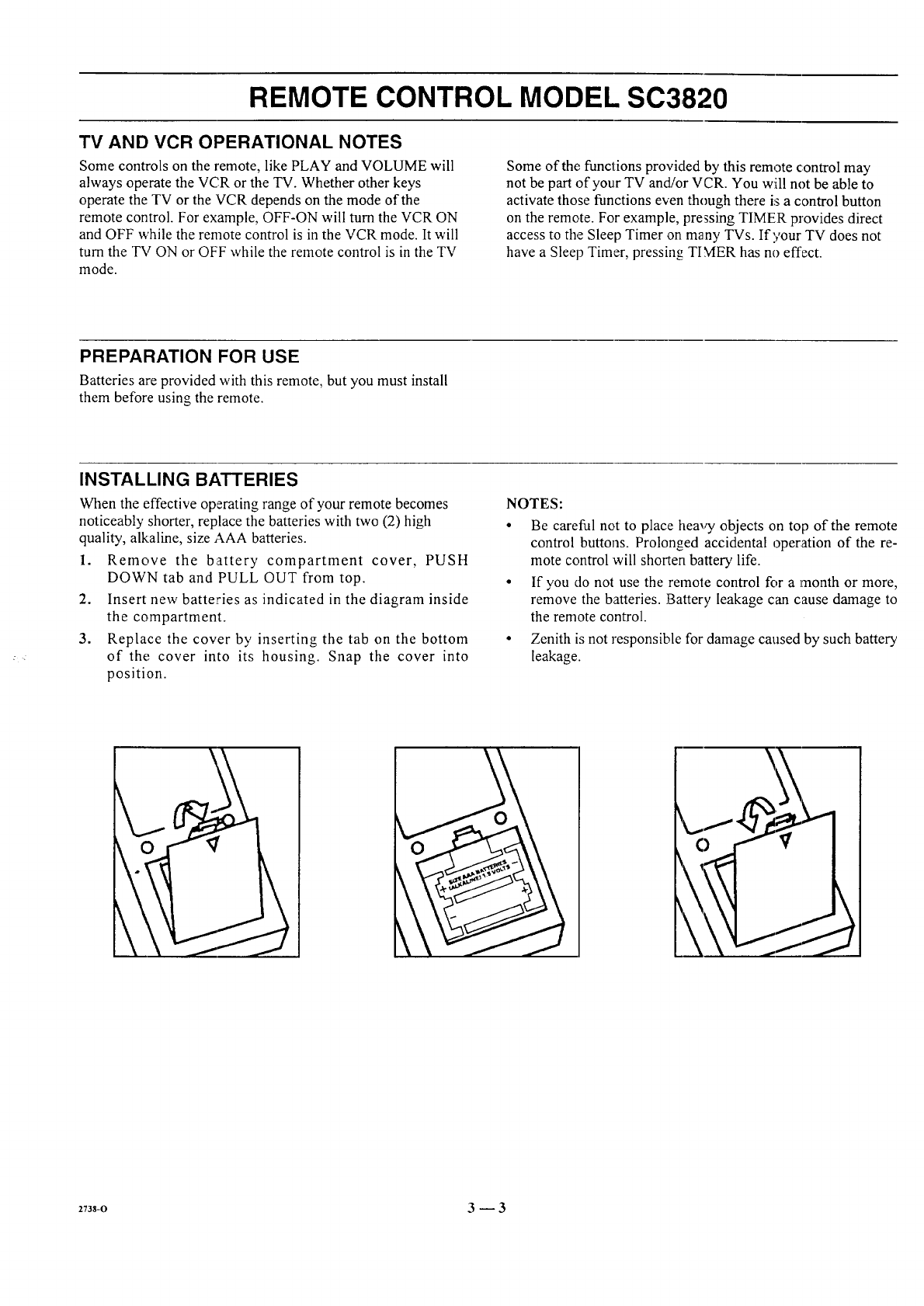
INSTALLING BATTERIES
When the effective operating range of your remote becomes
noticeably shorter, replace the batteries with two (2) high
quality, alkaline, size AAA batteries.
1. Remove the battery compartment cover, PUSH
DOWN tab and PULL OUT from top.
2. Insert new batteries as indicated in the diagram inside
the compartment.
3. Replace the cover by inserting the tab on the bottom
of the cover into its housing. Snap the cover into
position.
NOTES:
• Be careful not to place heavy objects on top of the remote
control buttons. Prolonged accidental operation of the re-
mote control will shorten battery life.
• If you do not use the remote control for a month or more,
remove the batteries. Battery leakage can cause damage to
the remote control.
• Zenith is not responsible for damage caused by such battery
leakage.
2738-0 3 --3
REMOTE CONTROL MODEL MBR3430
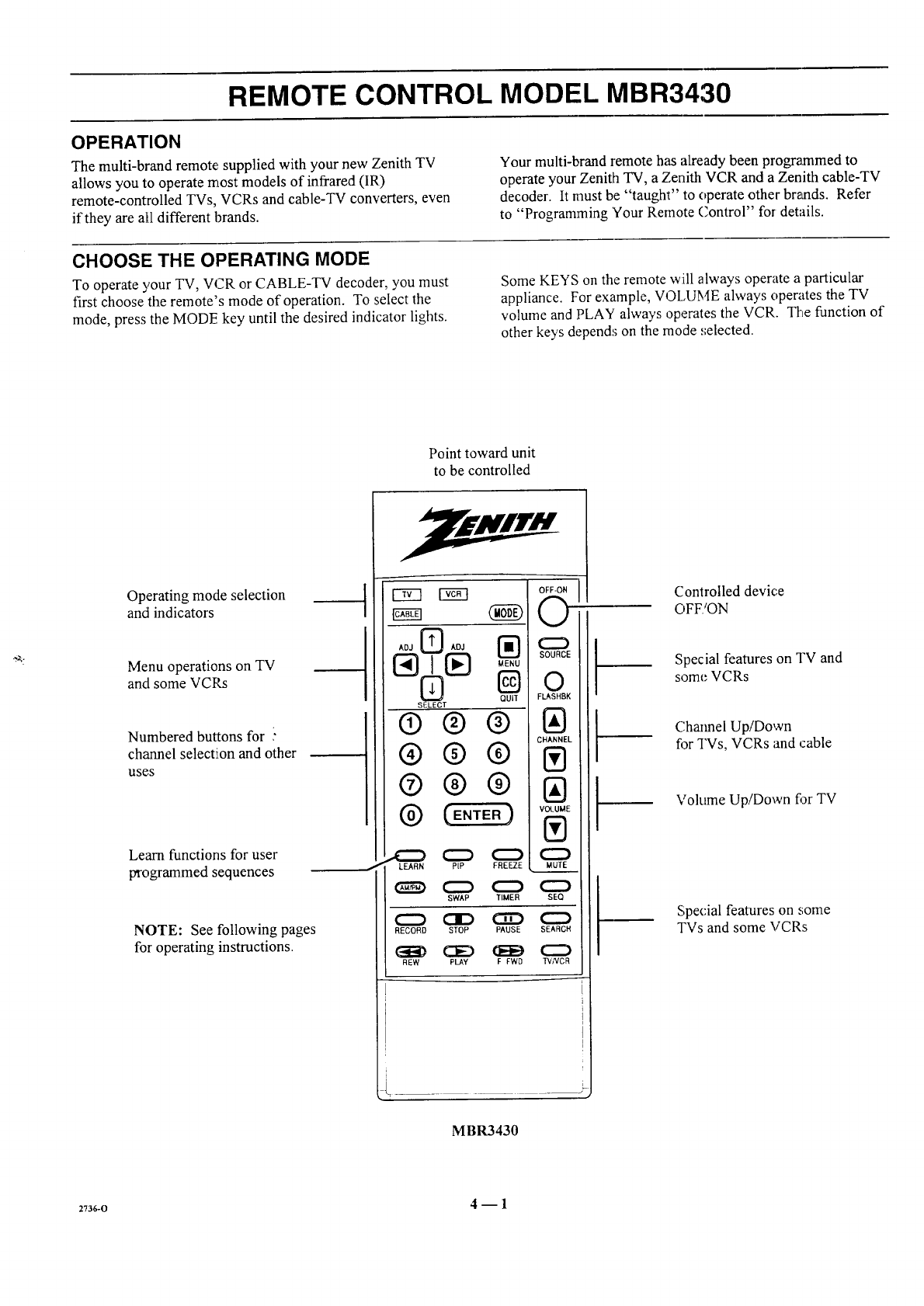
OPERATION
The multi-brand remote., supplied with your new Zenith TV
allows you to operate most models of infrared (IR)
remote-controlled TVs, VCRs and cable-TV converters, even
if they are aI1 different brands.
Your multi-brand remote has already been programmed to
operate your Zenith TV, a Zenith VCR and a Zenith cable-TV
decoder. It must be "taught" to operate other braaads. Refer
to "Programming Your Remote Control" for details.
CHOOSE THE OPERATING MODE
To operate your TV, VCR or CABLE-TV decoder, you must
first choose the remote's mode of operation. To select the
mode, press the MODE key until the desired indicator lights.
Some KEYS on the remote will always operate a particular
appliance. For example, VOLUME always operates the TV
volume and ]PLAY always operates the VCR. The function of
other keys depend,; on the mode .';elected.
Point toward unit
to be controlled
Operating mode selection
and indicators
Menu operations on TV
and some VCRs
Numbered buttons for
channel selection and other
uses
Learn functions for user
programmed sequences
NOTE: See following pages
for operating instructions.
Cw3 EEl
AOJ AOJ
SELECT
®®®
®@®
®®®
CZ_ (Z_D
LEARN PiP FREFTE
d
_(ZZ_ (:ZD O
SWAP TIMER SEQ
RECORD STOP PAUSE SEARCH
(_E_ CE£) (J_EE_(::Z:)
REW PLAY F FWD TVNCR
k
--
t--
!-
Controlled device
OFF/ON
Special features on TV and
some VCRs
Chaimel Up/Down
fi)r TVs, VCRs and cable
Volume Up/Down fi_r TV
Special features on some
TVs and some VCRs
MBR3430
27s_o 4-- 1
REMOTE CONTROL MODEL MBR3430
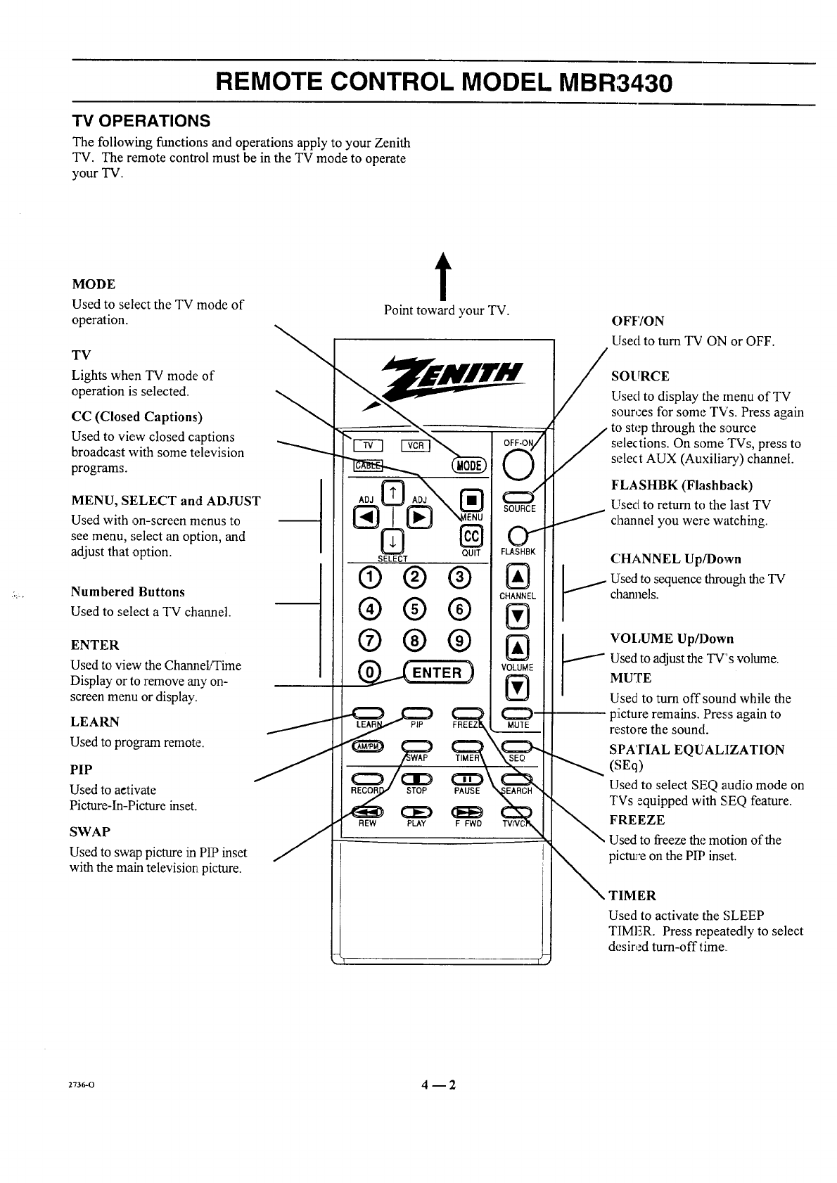
TV OPERATIONS
The following functions and operations apply to your Zenith
TV. The remote control must be in the TV mode to operate
your TV.
MODE
Used to select the TV mode of
operation.
TV
Lights when TV mode of
operation is selected.
CC (Closed Captions)
Used to view closed captions
broadcast with some television
programs.
MENU, SELECT and ADJUST
Used with on-screen menus to
see menu, select an option, and
adjust that option.
Numbered Buttons
Used to select a TV channel.
ENTER
Used to view the Channel/Time
Display or to remove any on-
screen menu or display.
LEARN
Used to program remote.
PIP
Used to aetivate
Picture-In-Picture inset.
SWAP
Used to swap picture in PIP inset
with the main televisiorLpicture.
t
Point toward your TV.
AOJ
SELECT
®®®
®®®
®®®
REW
PIP
STOP PAUSE
CED _E_
PLAY FFWD
OFF/ON
Used to turn TV ON or OFF.
SOURCE
Llsed to display the menu of TV
sources for some TVs. Press again
to step through the source
selections. On some TVs, press to
sele¢t AUX (Auxiliary) channel.
FLA SHBK (Flashback)
Usecl to return to the last TV
channel you were watching.
CHANNEL Up/Down
Used to sequence through the TV
charmels.
VOI,UME Up/Down
/Used to adjust the TV's volume.
MUTE
Used to turn off sound while the
piicture remains. Press again to
re,store the sound.
SPA'rIAE EQUALIZATION
(SEq)
Used to select SEQ audio mode on
TVs equipped with SEQ feature.
FREEZE
Used to freeze the motion of the
pic_'e on the PlY' inset.
TIMER
Used to activate the SLEEP
TIMER. Press repeatedly to select
desir,._d turn-offtime
2736-0 4 -- 2
REMOTE CONTROL MODEL MBR3430
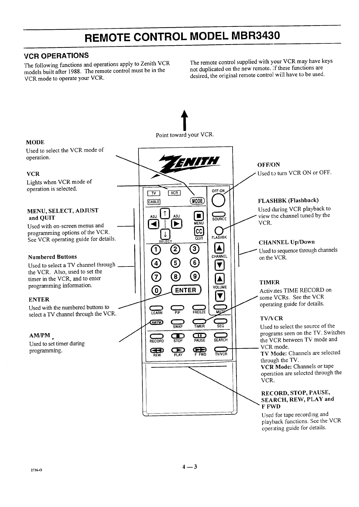
VCR OPERATIONS
The following functions and operations apply to Zenith VCR The remote control supplied with your VCR may have keys
models built after 1988. The remote control must be in the not duplicated on the new remote. '.£these functions are
VCR mode te operate your VCR. desired, the original remote control will have to be used.
MODE
t
Point toward your VCR.
Used to select the VCR rnode of
operation.
VCR
Lights when VCR mode; of
operation is selected.
MENU, SELECT, ADJUST
and QUIT
Used with on-screen menus and
programming options of the VCR.
See VCR operating guide for details.
Numbered Buttons
Used to select a TV channel through
the VCR. Also, used to set the
timer in the VCR, and to enter
programming information.
ENTER
Used with the numbered buttons to
select a TV channel throughthe VCR.
SOURCE
MENU
@ o I
FLASHBK
AM/PM
Used to set timer during
programming.
[Z}A0_
6
SELECT
J
QUIT
®®®
®®®
®®®
_.__ENTER )
LEARN PIP
SWAP
CHANNEL
VOLUME
C=:) C:::L.
TIMER SEQ
RECORD STOP PAUSE SEARCH
REW PLAY F FWD "rVWCR
OFF/ON
Used to turn VCR ON or OFF.
FLASHBK (Flashback)
IJsed (luring VCR playback to
J iew the channel tuned by the
VCR.
_,t CttANNEL Up/Down
Used to sequence _d_oughchannels
on the VCR.
TIMER
Activates TIME RECORD on
J so:me VCRs. Se_ the VCR
operating guide for details.
TV_'CR
Used to select the source of the
programs seen on the TV. Switches
the VCR between TV mode and
VCR mode.
TV Mode: Channels are selected
through the TV.
VCR Mode: Channels or tape
operation are selected through the
VCR.
RECORD, STOP, PAUSE,
SEARCH, REW, PLAY and
F FWD
Used for tape record:ing and
playback functions. See the VCR
operating guide fbr details.
2736-0 4 _ 3
REMOTE CONTROL MODEL MBR3430
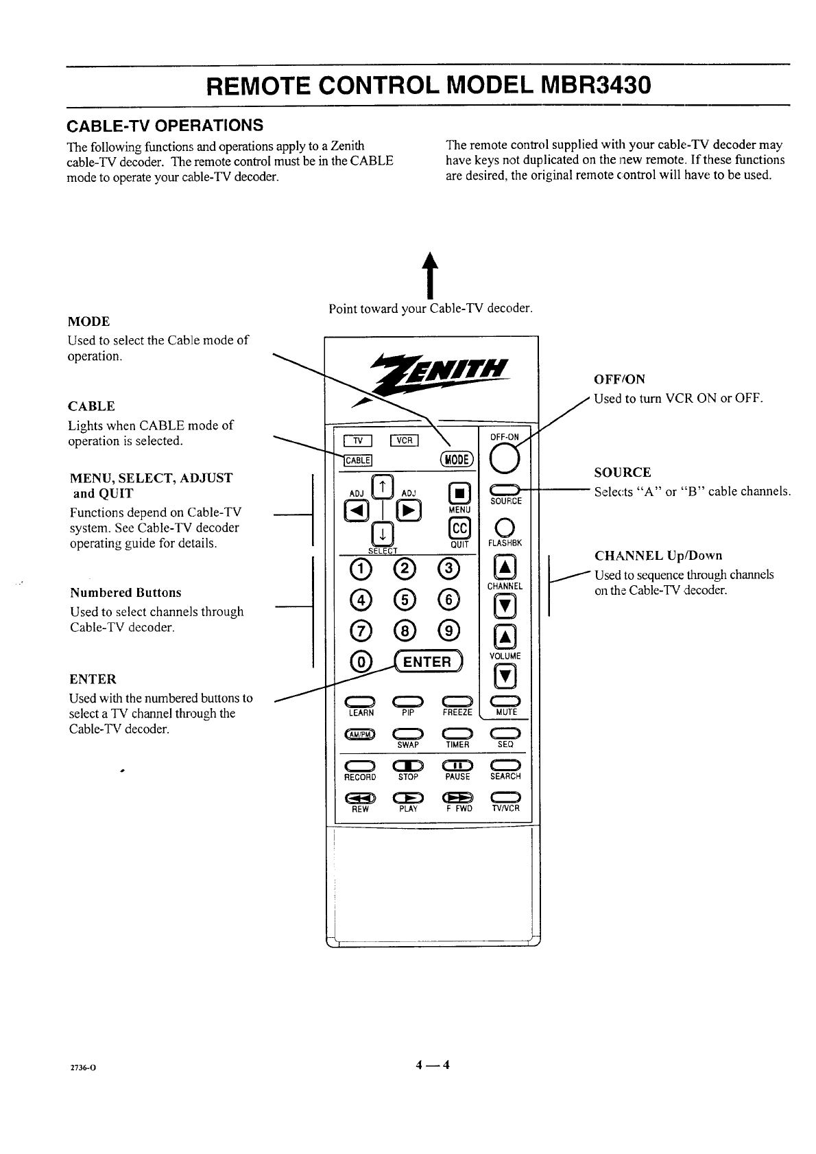
CABLE-TV OPERATIONS
The following functions and operations apply to a Zenith
cable-TV de,coder. The remote control must be in the CABLE
mode to operate your cable-TV decoder.
The remote control supplied with your cable-TV decoder may
have keys not duplicated on the Jlew remote. If these functions
are desired, the original remote control will haw,' to be used.
MODE
Used to select the Cab]Le mode of
operation.
CABLE
Lights when CABLE mode of
operation is selected.
MENU, SELECT, ADJUST
and QUIT
Functions depend on Cable-TV
system. See Cable-TV decoder
operating guide for details.
Numbered Buttons
Used to select channels through
Cable-TV decoder.
ENTER
Used with the numbered buttons to
select a TV channel through the
Cable-TV decoder.
t
Point toward your Cable-TV decoder.
(Ng
@oA0,
[_ MENU
QUIT
SELECT
®®®
®®®
®®®
ENTER )
SOURCE
0
FLASHBK
IAI
CHANNEL
IVl
IAI
VOLUME
IVI
C:D
LEARN PIP FREEZE MUrE
SWAP TIMER SEQ
RECORD STOP PAUSE SEARCH
REW PLAY FFWD TVNCR
OFF/ON
Used to turn VCR ON or OFF.
SOURCE
Selects "A" or "B" cable channels.
CHANNEL Up/Down
Used, to sequence through channels
on the Cable-TV ,decoder.
2736-o 4-- 4
REMOTE CONTROL MODEL MBR3430
PREPARATION FOR USE
Batteries are provided with this remote, but you must install
them before using the remote.
INSTALLING BATTERIES
When the effective operating range of your remote becomes
noticeably shortez:,replace the batteries with two high-quality,
alkaline, size AAA batteries.
Zenith is not responsible for damage caused by battery
leakage.
After installing new batteries, the remote conLtrolwill set itself
to Zenith brand codes, as follows: TV=101, VCR=201 and
CABLE=30I.
If you are going to operate equipment that uses different
codes, the remote must be reprogrammed for those codes.
Step 1.
I
Step 2. Step 3.
2736-0 4--5
REMOTE CONTROL MODEL MBR3430
PROGRAMMING BRAND CODES
Introduction
Before using your new remote control, it must be programmed
to recognize the brands of equipment it will be used to
operate. If you are using a Zenith VHS VCR or a Zenith
cab[e-TV decoder, the remote has already been programmed
for you.
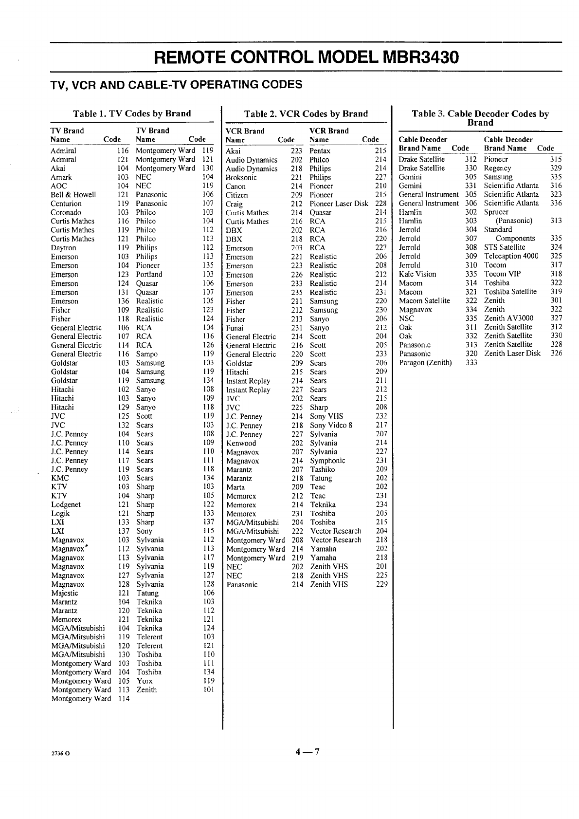
Find the code that corresponds to each brand and type of
equipment you are going to operate. Refer to Tables 1,2 and 3.
For example, if you were programming the remote for use
with a Zenith TV, you would look for "Zenith" in "Table 1",
and find code "101."
Write the brand codes for your equipment on the following
lines.
TV CODE:
CABLE CODE:
VCR CODE:
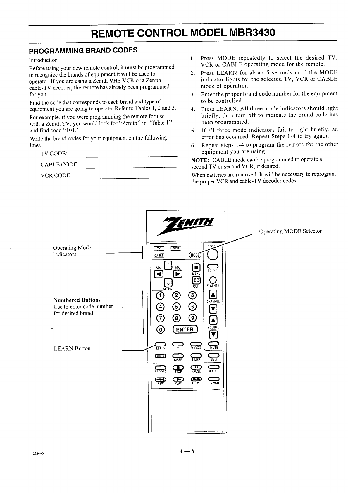
1. Press MODE repeatedly to select the: desired TV,
VCR or CABLE operating mode for the remote.
2. Press LEARN for about 5 seconds unl:il the MODE
indicator lights for the selected TV, VCR or CABLE
mode of operation.
3. Enter the proper brand code number for the equipment
to be controlled.
4. Press LEARN. All three :mode indicators should light
briefly, then turn off to indicate the brand code has
been programmed.
5. If all :three mode indicators fail to light briefly, an
error has occurred. Repeat Steps 1-4 to try again.
6. Repeat steps 1-4 to program the remote for the other
equipment you are using.
NOTE: CABLE mode can be programmed to operate a
second TV or second VCR, iLfdesired.
When batteries are removed: It will be necessary to reprogram
the proper VCR and cable-TV cecoder codes.
Operating Mode
Indicators
Numbered Buttons
Use to enter code number
for desired brand.
LEARN Button
I
AD3 I_ ADJ
SELECT Qu ic L
® ®®
®®®
® ® ®
LEARN PIP FREEZE
SWAP TIMER SEQ
C::) C]D CE:) (::::::)
RECORD STOP PAUSE SEARCH
REW PLAY F FWD TVNCR
Operating MODE Selector
z73wo 4_6
REMOTE CONTROL MODEL MBR3430
TV, VCR AND CABLE-TV OPERATING CODES
Table 1. TV Codes by Brand
TV Brand rv Brand
Name Code Name Code
Admiral 116 Montgomery Ward 119
Admiral 121 Montgomery Ward 121
Akai 104 Montgomery Ward 130
Amark 103 NEC 104
AOC 104 NEC 119
Bell & Howell 121 Panasonic 106
Centurion 119 Panasonic 107
Coronado 103 Philco 103
Curtis Mathes 116 Philco 104
Curtis Mathes 119 Philco 112
Curtis Mathes 121 Philco 113
Daytron 119 Philips 112
Emerson 103 Philips 113
Emerson 104 Pioneer 135
Emerson 123 Portland 103
Emerson 124 Quasar 106
Emerson 131 Quasar 107
Emerson 136 Realistic 105
Fisher 109 Realistic 123
Fisher 118 Realistic 124
General Electric 106 RCA 104
General Electric 107 RCA 116
General Electric 114 RCA 126
General Electric 116 Sampo 119
Goldstar 103 Samsung 103
Goldstar 104 Samsung 119
Goldstar 119 Samsung 134
Hitachi 102 Sanyo 108
Hitachi 103 Sanyo 109
Hitachi 129 Sanyo 118
JVC 125 Scott 119
JVC 132 Sears 103
J.C. Penney 104 Sears 108
J.C. Penney 110 Sears 109
J.C. Penney 114 Sears 110
J.C. Penney 117 Sears I 11
J.C. Penney 119 Sears 118
KMC 103 Sears 134
KTV 103 Sharp 103
KTV 104 Sharp 105
Lodgenet 121 Sharp 122
Logik 121 Sharp 133
LXI 133 Sharp 137
LXI 137 Sony 115
Magnavox 103 Sylvania 112
Magnavox _ 112 Sylvania 113
Magnavox 113 Sylvania 117
Magnavox 119 Sylvania 119
Magnavox 127 Sylvania 127
Magnavox 128 Sylvania 128
Majestic 121 Tatung 106
Marantz 104 Teknika 103
Marantz 120 Teknika 112
Memorex 121 Teknika 121
MGA/Mitsubishi 104 Teknika 124
MGA/Mitsubishi 119 Telerent 103
MGA/Mitsubishi 120 Telerent 121
MGA/Mitsubishi 130 Toshiba 1I0
111
134
119
10l
Montgomery Ward 103 Toshiba
Montgomery Ward 104 Toshiba
Montgomery Ward 105 Yorx
Montgomery Ward 113 Zenith
Montgomery Ward 114
Table 2. VCR Codes by Brand
VCR Brand VCR Brand
Name Code Name Code
Akai 223 Pentax 215
Audio Dynamics 202 Philco 214
Audio Dynamics 218 Philips 214
Broksonic 221 Philips 227
Canon 214 Pioneer 210
Citizen 209 Pioneer 215
Craig 212 Pioneer Laser Disk 228
Curtis Mathes 214 Quasar 21,1
Curtis Mathes 216 RCA 215
DBX 202 RCA 216
DBX 218 RCA 220
Emerson 203 RCA 227
Emerson 221 Realistic 206
Emerson 223 Realistic 208
Emerson 226 Realistic 212
Emerson 233 Realistic 214
Emerson 235 Realistic 231
Fisher 211 Samsung 220
Fisher 212 Samsung 230
Fisher 213 Sanyo 2013
:unai 23l Sanyo 212
General Electric 214 Scott 204
General Electric 216 Scott 20:5
General Electric 220 Scott 233
Goldstar 209 Sears 206
Hitachi 215 Sears 209
Instant Replay 214 Sears 211
Instant Replay 227 Sears 212
JVC 202 Sears 215
JVC 225 Sharp 208
J.C. Penney 214 Sony VHS 232
J.C. Penney 218 Sony Video 8 21"7
J.C Penney 227 Sylvania 20'7
Kenwood 202 Sylvania 21,1
Magnavox 207 Sylvania 22'7
Magnavox 214 Symphonic 231
Marantz 207 Tashiko 20!9
Marantz 218 Tatung 202
Marta 209 Teac 202
Memorex 212 Teac 231
Memorex 214 Teknika 23.1
Memorex 231 Toshiba 205
MGA/Mitsubishi 204 Toshiba 21:5
MGA/Mitsubishi 222 Vector Research 204
21:']
202
218
201
225
22'9
Montgomery Ward 208 Vector Research
Montgomery Ward 214 Yamaha
Montgomery Ward 219 Yamaha
NEC 202 Zenith VHS
NEC 218 Zenith VHS
Panasonic 214 Zenith VHS
Table 3. Cable Decoder Codes by
Brand
Cable Decoder Cable Decoder
Brand Name Code Brand Name Code
Drake Sal_.ellile 312 Pioneer 315
Drake Sa",ellile 330 Regency 329
Gemini 305 Samsung 335
Gemini 331 Scientific Atlanta 316
General Instrument 305 Scienlific Atlanta 323
General Instrument 306 Scientific Atlanta 336
Hamlin 302 Sprucer
Hamlin 303 (Panasonic) 313
Jerrold 304 Standard
Jerrold 307 Components 335
Jerrold 308 STS Satellite 324
Jerrold 309 Telecaption 4000 325
Jerrold 310 Tocom 317
Kale Vision 335 Tocom VIP 318
Macom 314 Toshiba 322
Macom 321 Toshiba Satellite 319
Macom Satel ite 322 Zenith 301
Magnavox 334 Zenith 322
NSC 335 Zenith AV3000 327
Oak 311 Zenith Satellite 312
Oak 332 Zenith Satellite 330
Panasonic 313 Zenith Satellite 328
Panasonic 320 Zenith Laser Disk 326
Paragon (Zenith) 333
2736-0 4 -- 7
QUICK REFERENCE TO ON-SCREEN MENUS
AVAILABLE MENUS
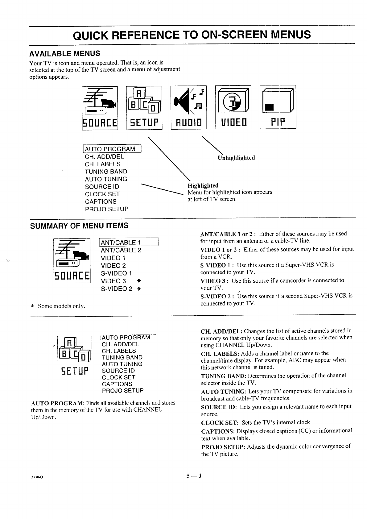
Your TV is icon and menu operated. That is, an icon is
selected at the top of the TV screen and a menu of adjustment
options appears.
\
RUOlO UIOEO PIP
[AUTO PROGRAM
CH. ADD/DEL
CH. LABELS
TUNING BAND
AUTO TUNING
SOURCE ID
CLOCK SET
CAPTIONS
PROJO SETUP
\Unhighlighted
Highlighted
Menu for highlighted icon appears
at left of TV screen.
SUMMARY OF MENU ITEMS
50UFIEE
IANT/CABLE 1
ANT/CABLE 2
VIDEO 1
VIDEO 2
S-VIDEO 1
VIDEO 3
S-VIDEO 2 *
* Some models only.
ANT/CABLE 1 or 2 :Either of these sources may be used
for input from an antenna or a cable-TV line,.
VIDEO 1 or 2 : Either of these sources may be used for input
from a VCR.
S-VIDEO 1 : Use this source ifa Super-VtfS VCR is
connected to your TV.
VIDEO 3 : Use this source iifa camcorder is connected to
your TV.
S-VIDEO 2 : £Jse this source ifa second Super-VHS VCR is
connected to your TV.
_ ] IAUTOPROGRAM
l CH. ADD/DEL
CH. LABELS
iTUNING BAND
i AUTO TUNING
5ETUP SOURCEID
CLOCK SET
CAPTIONS
PROJO SETUP
AUTO PROGRAM: Finds all available channels and stores
them in the memory of the TV for use with CHANNEL
Up/Down.
CH. ADD/DEL: Changes the list of active channels stored in
memory so that only your favorite channels are selected when
using CHANNEl_, Up/Down
CH. LABELS: Adds a channel label or narae to the
channel/time display. For example, ABC may appear when
this network channel is tuned.
TUNING BAND: Determines the operation of the channel
selector inside the TV.
AUTO TUNING: Lets your TV compensate for variations in
broadcast and cable-TV frequencies.
SOURCE ID: Lets you assign a relevant name to each input
source.
CLOCK SET: Sets the TV's internal clock.
CAPTIONS: Displays closed captions (CC) or informational
text when available.
PROJO SETUP: Adjusts the dynamic color convergence of
the TV picture.
z738-o 5_ 1

QUICK REFERENCE TO ON-SCREEN MENUS
SUMMARY OF MENU ITEMS
\
RUOIO
IBASS
TREBLE
BALANCE
AUDIO
SEQ
SURROUND
BASS: Adjusts the BASS (low-fi'equency) level.
TREBLE: Adjusts the TPd_BI.E (high-fTequency) level.
BALANCE: Adjusts the BALANCE of sound between the
left and right speakers for stereophonic programs.
AUDIO MODE.: Allows for receiving a Second Audio
Program (SAP), such as a program broadcast with two audio
portions (typically two languagles), or lets you :select
stereophonic (STEREO) or monaural (MONO) speaker
operation.
SEQ: Turns on an enhanced stereo mode.
SURROUND: Adjusts Stu_otmd Sound volume when used
with separately supplied Surround Sound speakers.
UIOEO
[CONTRAST
BRIGHTNESS
COLOR
TINT
SHARPNESS
COLOR TEMP
VIDEO FILTER
AUTO FLESH
PICTURE PREF
CONTRAST: Adjusts the overall contrast and color level of
the picture.
BRIGHTNESS: Adjusts the brightness level of black areas in
the picture.
COLOR: Adjusts the intensity of the colo_; in _hepicture.
TINT: Adjusts the color of the flesh tone.,;.
SHARPNESS: Adjusts the clmity of the edges of objects for the
clearest possible picture.
COLOR TEMP: Changes the "color temperature" or picture
white bahmce between cooler natural whilles and warmer (red)
colors.
VIDEO FILTER: Reduces video "noise" or interference in
dark picture areas resulting in clearer overall pictures.
AUTO FLESH: Automatically maintains natural skin tones
under changing scene and video source conditions.
PICTURE PREF: Lets you decide if you want to use your
own CUSTOM video settings, the factory P1ZESET video
settings, or the THEATER video settings for optimum
viewing in low-light conditions.
PIF
* Some models only.
ICH. GUIDE
CH. REVIEW
PIP SOURCE
PIP COLOR
PIP TINT
PIP SIZE
CH. GUIDE: Provides a visual review of all channels in the
channel scan memory for the currently selected ANT/
CABLE source.
CH. REVIEW: Provides a visual review of the last three (3)
channels tuned on the TV.
PIP SOURCE: Lets you select the equipment that supplies
the picture to the PIP inset.
PIP COLOR: Adjusts the intensity of the colors in the PIP
inset.
PIP TINT: Adjusts the color of the flesh tortes.
PIP SIZE: Lets you choose between seeing a larger or
smaller PIP inset.
2vss-o 5 _ 2
QUICK REFERENCE TO ON-SCREEN MENUS
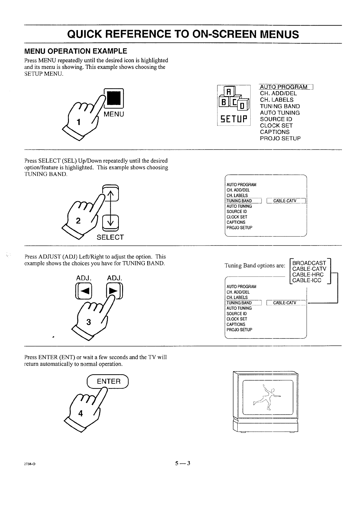
MENU OPERATION EXAMPLE
!PressMENU repeatedly until the desired icon is highlighted
and its menu :isshowing. This example shows choosing the
',SETUP MENU.
MENU
ALITO PROGRAM
CH. ADD/DEL
CH. I_ABELS
TUN!!NG BAND
AUTO TUNING
SOURCE ID
CLOCK SET
CAPTIONS
PROJO SETUP
Press SELECT (SEL) Up/Down repeatedly until the desired
option/feature is highlighted. This example shows choosing
TUNING BAND.
AUTO PROGRAM
CH.ADD/DEL
CH.LABELS
TUNING BAND
AUTO TUNING
SOURCE ID
CLOCK SET
CAPTIONS
PROJO SETUP
] [ CABLE-CATV
J
Press ADJUST (ADJ) Left/Right to adjust the option. This
example shows the choices you have for TUNING BAND.
ADJ. ADJ.
Tuning Band options are:
AUTO PROGRAM
CH. ADD/DEL
CH. LABELS
TUNING BAND
AUTO TUNING
SOURCE ID
CLOCK SET
CAPTIONS
PROJOSETUP
Ii 'OADCASTq
ABLE-CATV/
ABLE-HRC I--]
ABLE-ICC J I
] [ CABLE-CAW
]PressENTER. (ENT) or wait a few seconds and the TV will
remm automatically to normal operation.
:_738-o 5-- 3
SOURCE MENU
SDUREE
IANT/CABLE 1
ANT/CABLE 2
VIDEO 1
VIDEO 2
S-VIDEO 1
VIDEO 3 *
S-VIDEO 2 Some models only
Source Menu
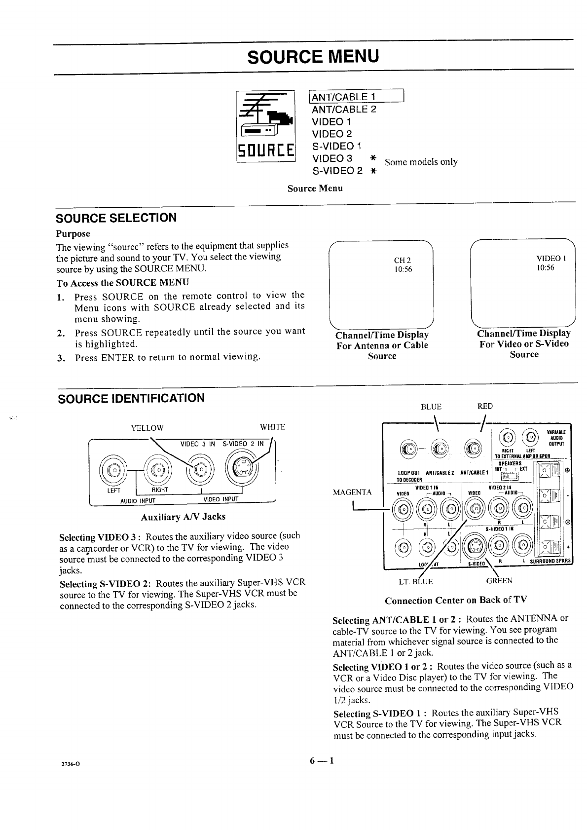
SOURCE SELECTION
Purpose
The viewing "source" refers to the equipment that supplies
the picture and sound to your TV. You select the viewing
source by using the SOURCE MENU.
To Access the SOURCE MENU
1. Press SOURCE on the remote control to view the
Menu icons with SOURCE already selected and its
menu showing.
2. Press SOURCE repeatedly until the source you want
is highlighted.
3. Press ENTER to return to normal viewing.
f
CH 2
10:56
J
Channel/Time Display
For Antenna or Cable
Source
h
VIDEO 1
10:56
J
Channel/Time Display
For Video or S-Video
Source
SOURCE IDENTIFICATION
YELLOW WHITE
AUDIO INPU_ IGHT i VIDEO INPUT
Auxiliary A/V Jacks
Selecting VIDEO 3 : Routes the auxiliary video source (such
as a camcorder or VCR) to the TV for viewing. The video
source must be connected to the corresponding VIDEO 3
jacks.
Selecting S-VIDEO 2: Routes the auxiliary Super-VHS VCR
source to the TV for viewing. The Super-VHS VCR must be
connected to the corresponding S-VIDEO 2 jacks.
MAGENTA
I
BLUE RED
_1--- RtG_T LEFT
_'_/' _ TO EXTERHAL AMP ORSPKR
SPEkIERS
tOoPOUZA.T/C.mEZ_.T_tE1 ,,,r_=_,trrII!'ol,lLt[_
VIDEO _ltUOlO _ VlO[O _AIIDIO_ I fl_q Ih{[ I .
:RI L . _
, ,o,,ou,o,.,,
LT. BLUE G REE2q
Connection Center on Back of TV
Selecting ANT/CABLE ][or 2 : Routes the ANTENNA or
cable-TV source to the TV for viewing. You see program
material from whichever signal source is connected to the
ANT/CABLE 1 or 2jack.
Selecting VIDEO 1 or 2 :Routes the video source (such as a
VCR or a Video Disc player) to the TV fbr viewing. The
video source must be connected to the corresponding VIDEO
1/2jacks.
Selecting S-VIDEO 1 : Rotates the auxiliary Super-VHS
VCR Source to the TV for viewing. The Super-VHS VCR
must be connected to the con'esponding input jacks.
27_o 6 -- 1
SETUP MENU
To Access SETUP Menu
Refer to the "Using On-Screen
Menus" section for details.
Before Using SETUP Menu
Connect and turn ON all external
equipment, such as cable TV decoder,
VCR, etc. before using any item on
the SETUP Menu.
SETUP i
Main
IAUTO PROGRAM
CH. ADD/DEL
CH. LABELS
TUNING BAND
AUTO TUNING
SOURCE ID
CLOCK SET
CAPTIONS
PROJO SETUP
Setup Menu
5ETUI::'
[SOURC[- ID
CLOCK SET
CAPTIONS
PROJO SETUP
Setlap Menu for Video
and S-Video Sources
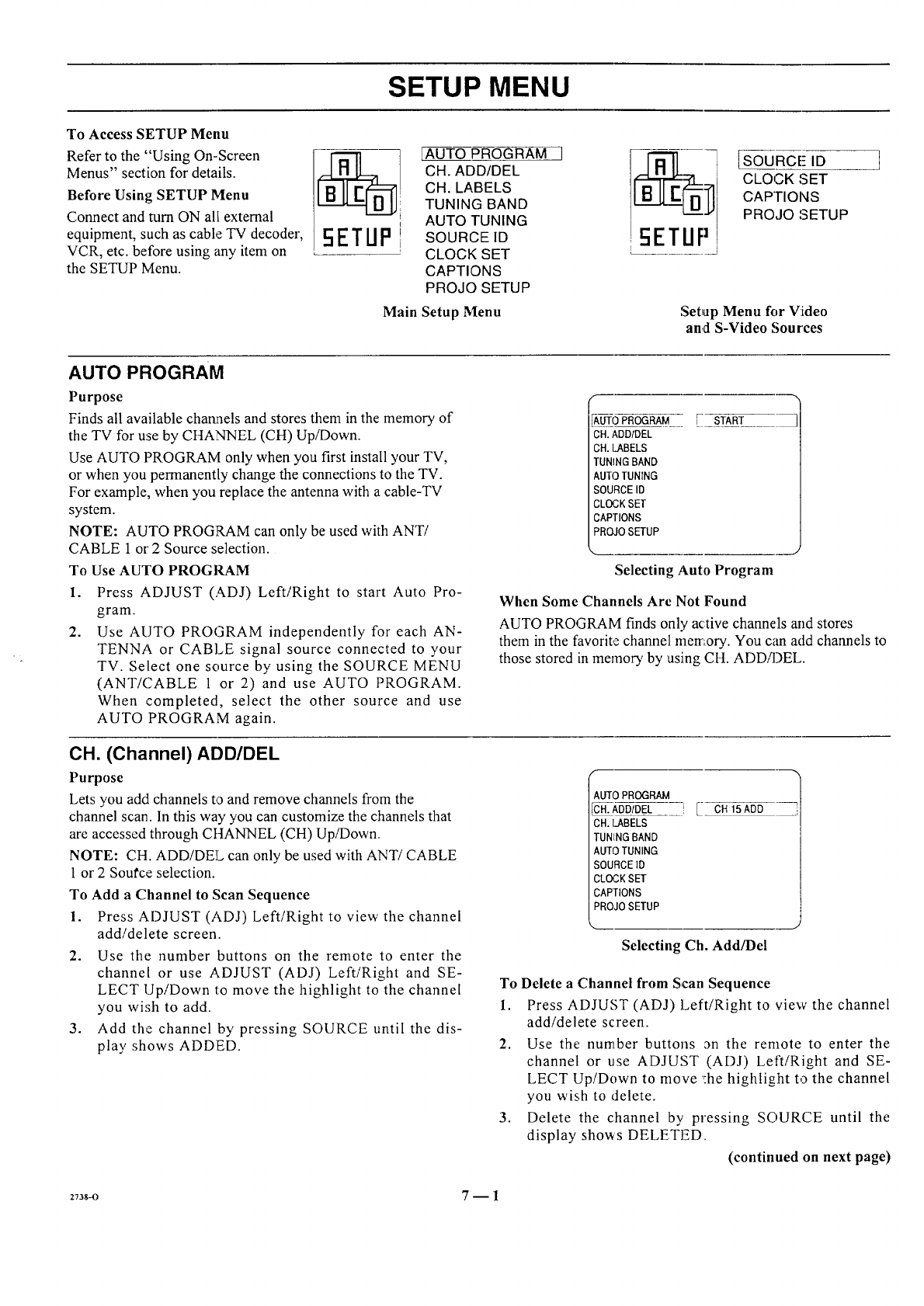
AUTO PROGRAM
Purpose
Finds all available channels and stores them in the memory of
the TV for use by CHANNEL (CH) Up/Down.
Use AUTO PROGRAM only when you first install your TV,
or when you permanently change the connections to the TV.
For example, when you replace the antenna with acable-TV
system.
NOTE: AUTO PROGRAM can only be used with ANT/
CABLE 1 or 2 Source selection.
To Use AUTO PROGI_M
1. Press ADJUST (ADJ) Left/Right to start Auto Pro-
2.
gram.
Use AUTO PROGRAM independently for each AN-
TENNA or CABLE signal source connected to your
TV. Select one source by using the SOURCE MENU
(ANT/CABLE 1 or 2) and use AUTO PROGRAM.
When completed, select the other source and use
AUTO PROGRAM again.
AUTO PROGRAM
CH.ADD/DEL
CH.I_ABELS
TUNING BAND
AUTO TUNING
SOURCE ID
CLOCK SET
CAPTIONS
PROJO SETUP
START
Selecting Auto Program
CH. (Channel) ADD/DEL
Purpose
Lets you add channels to and remove channels from the
channel scan. In this way you can customize the channels that
are accessed through CHANNEL (CH) Up/Down.
NOTE: CH. ADD/DEL can only be used with ANT/CABLE
1 or 2 Source selection.
To Add a Channel to Scan Sequence
1. Press ADJUST (ADJ) Left/Right to view the channel
add/delete screen.
2. Use the number buttons on the remote to enter the
channel or use ADJUST (ADJ) Left/Right and SE-
When Some Channels Are Not Found
AUTO PROGRAM finds only"active channels and stores
them in the favorite channel memory. You can add channels to
those stored in memory by using CH. ADD/DEL.
3°
LECT Up/Down to move the highlight to the channel
you wish to add.
Add the channel by pressing SOURCE until the dis-
play shows ADDED.
AUTO PROGRAM
CH. ADD/DEL
CH. I.ABELS
TUNING BAND
AUTO TUNING
SOURCE ]D
CLOCK SET
CAPTIONS
PROJO SETUP
! [ CH 15ADD
''_nmn
Selecting Ch. Add/Del
To Delete aChannel from Scan Sequence
1. Press ADJUST (ADJ) Left/Right to view the channel
add/delete screen.
2. Use the number buttons an the remote to enter the
channel or use ADJUST (ADJ) Left/Right and SE-
LECT Up/Down to move :he highlight to the channel
you wish to delete.
3. Delete the channel by pressing SOURCE until the
display shows DELETED.
(continued on next page)
273s-o 7--1
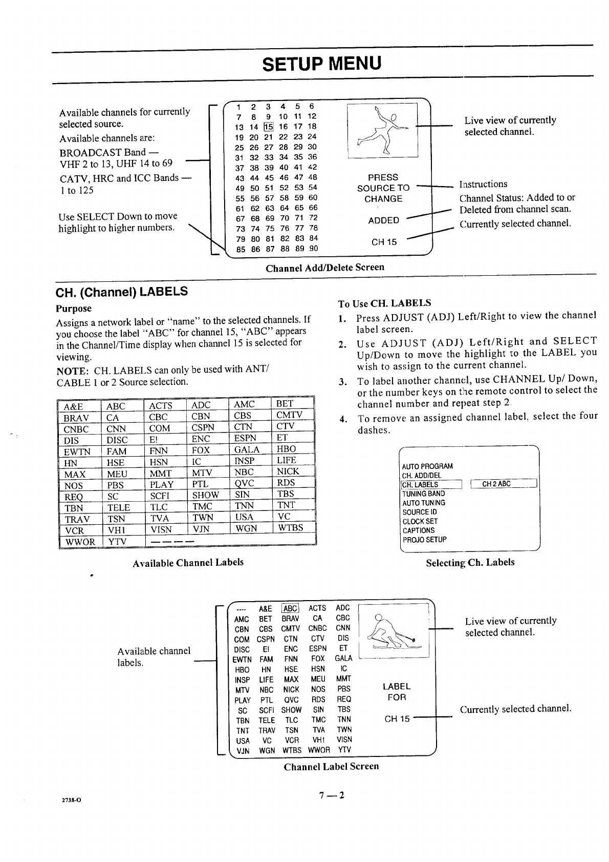
SETUP MENU
Available channels for currently
selected source.
Available channels axe:
BROADCAST Banct
VHF 2 to 13, UHF 14 to 69
CATV, HRC and ICC Bands
1 to 125
Use SELECT Down to move
highlight to higher numbers. "_
-- (- 1
7
13
19
25
31
37
43
49
55
61
67
73
79
85
23
8 9
14 [_
20 21
26 27
32 33
38 39
44 45
50 51
56 57
62 63
68 69
74 75
80 81
86 87
456
10 11 12
16 17 18
22 23 24
28 29 30
34 35 36
40 41 42
46 47 48
52 53 54
58 59 60
64 65 66
70 71 72
76 77 78
82 83 84
88 89 90
PRESS
SOURCETO
CHANGE
ADDED _"
CH 15
,)
Channel Add/Delete Screen
_. Live view of currently
selected channel.
_. I:nstructions
Channel Stalus: Added to or
_._. Deleted from ch_mnel scan.
I- Currently selected channel.
CH. (Channel) LABELS
Purpose
Assigns a network label or "name" to the selected channels. If
you choose the label "ABC" for channel 15, "ABC" appears
in the Channel/Time display when channel 15 is selected for
viewing.
NOTE: CH. LABELS can only be used with ANT/
CABLE 1 or 2 Source selection.
A&E ABC ACTS
BRAV CA CBC
CNBC CNN COM
DIS DISC E!
EWTN FAM FNN
HN HSE HSN
MAX MEU MMT
NOS PBS PLAY
REQ SC SCFI
TBN TELE TLC
TRAV TSN TVA
VCR VH 1 VISN
WWOR YTV
ADC AMC
CBN CBS
CSPN CTN
ENC ESPN
FOX GALA
IC INSP
MTV NBC
PTL qvc
SHOW SIN
TMC TNN
TWN USA
VJN WGN
BET
CMTV
CTV
ET
HBO
LIFE
NICK
RDS
TBS
TNT
VC
WTBS
Available Channel Labels
To Use CH. LABELS
1. Press ADJUST (ADJ) Left/Right to view the channel
label screen.
2. Use ADJUST (ADJ) Left/Right and SELECT
Up/Down to move the highlight _Eothe LABEL you
wish to assign to the current channel.
3. To label another channd, use CHANNEL Up/Down,
or the number keys on the remote control to select the
channel number and repeat step 2
4. To remove an assigned channel label, select the four
dashes.
tUTO PROGRAM
CH. ADD/DEL
_H. LABELSS_ { CH2ABC
TUNING BAND
AUTO TUNING
SOURCE ID
CLOCK SET
('APTIONS
PROJO SETUP
Selecting Ch. Labels
._J
Available channel
labels.
t r
AMC
CBN
COM
DISC
EWTN
HBO
INSP
MTV
PLAY
SC
TBN
TNT
USA
VJN
A&E _ ACTS ADC
BET BRAY CA CBC
CBS CMIV CNBC CNN
CSPN CTN CTV DIS
El ENC ESPN El"
FAM FNN FOX GALA
HN HSE HSN IC
LIFE MAX MEU MMT
NBC NICK NOS PBS
PTL OVC RDS BEQ
SCFI SHOW SIN TBS
TELE TLC TMC TNN
TRAV TSN I'VA TWN
VC VCR VH1 VISN
WGN WTBS WWOR YTV
i
LABEL
FOR
7'
!
Channel Label Screen
GH15
Live view of currently
selected channel.
Currently selected channel.
27ss-o 7_ 2
SETUP MENU
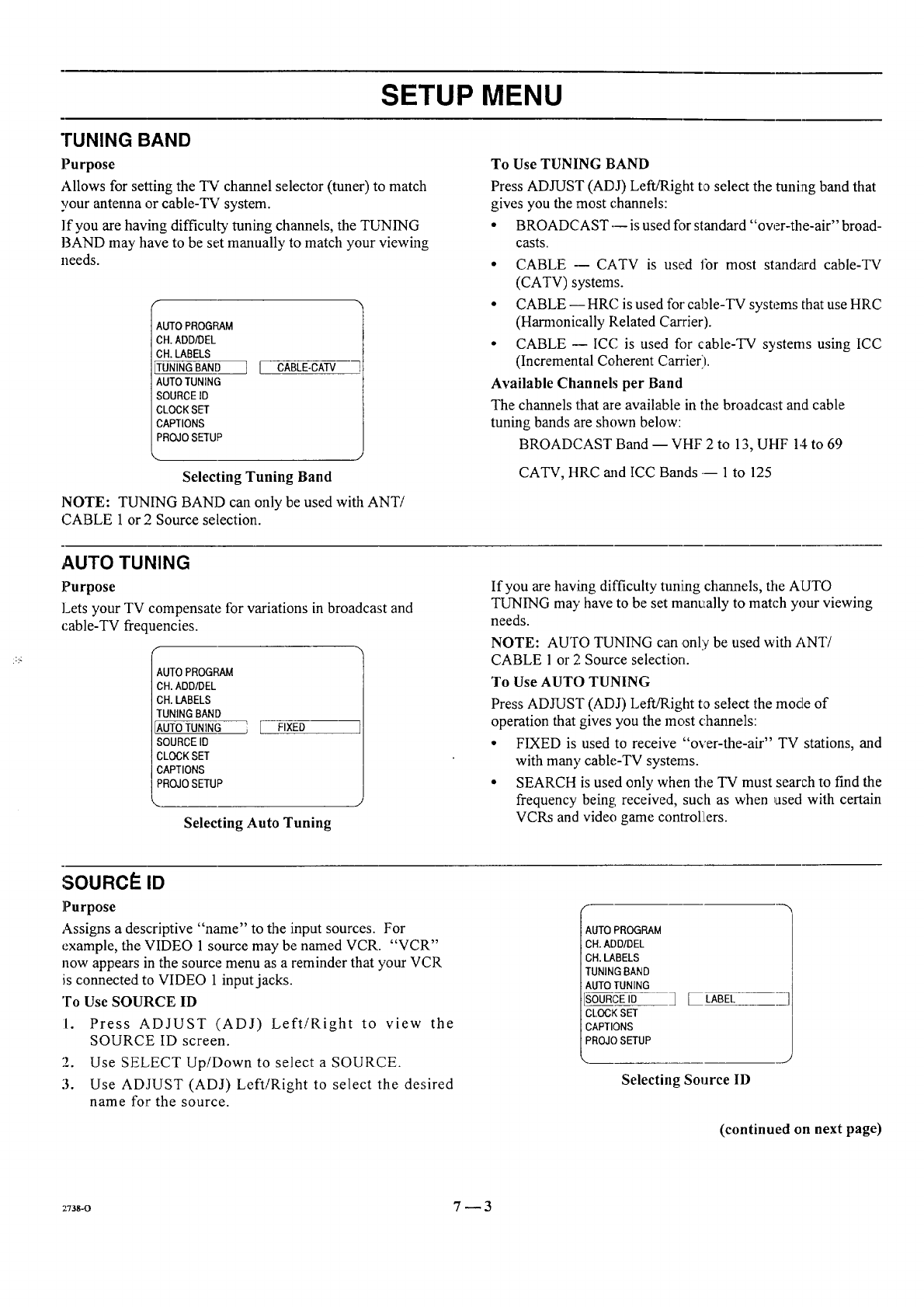
TUNING BAND
Purpose
Allows for setting the TV channel selector (tuner) to match
your antenna or cable-TV system.
lfyou are having difficulty tuning channels, the TUNING
BAND may have to be set manually to match your viewing
needs.
AUTO PROGRAM
CH. ADD/DEL
ell. LABELS
TUNING BAND
AUTO TUNING
SOURCE ID
CLOCK SET
CAPTIONS
PROJO SETUP
][CABLE-CAW
k. j
Selecting Tuning Band
NOTE: TUNING BAND can only be used with ANT/
CABLE 1 or 2 Source selection.
To Use TUNING BAND
Press ADJUST (ADO LefiJRight to select the tuning band that
gives you the most channels:
• BROADCAST---is used for standard "over-the-air" broad-
casts.
• CABLE --- CATV is used lbr most standard cable-TV
(CATV) systems.
• CABLE-- HRC is used for cable-TV systems that use HRC
(Harmonically Related Cawier).
• CABLE -- ICC is used for cable-TV systems using ICC
(Incremental Coherent Carrier'l.
Available Channels per Band
The channels that are available in the broadcast and cable
tuning bands are shown below:
BROADCAST Band -- VHF 2 to 13, UHF 14 to 69
CATV, HRC and ICC Bands .-- 1 to 125
AUTO TUNING
Purpose
]Letsyour TV compensate for variations in broadcast and
cable-TV frequencies.
AUTO PROGRAM
CH. ADD/DEL
CH. LABELS
TUNING BAN[)
AUTO TUNING
SOURCE ID
CLOCK SET
CAPTIONS
PROJO SETUP
FIXED
Selecting Auto Tuning
If you are having difficulty tuning channels, the AUTO
TUNING may have to be set manually to match your viewing
needs.
NOTE: AUTO TUNING can only be used with ANT!
CABLE 1 or 2 Source selection.
To Use AUTO TUNING
Press ADJUST (ADJ) Left!Right to select the mode of
operation that gives you the most channels:
• FIXED is used to receive "over-the-air" TV stations, and
with man 3, cable-TV systems.
• SEARCH is used only when the TV must search to fred the
frequency being received, such as when used with certain
VCRs and video game controllLers.
SOURCe: ID
]Purpose
Assigns a descriptive "name" to the input sources. For
example, the VIDEO 1 source may be named VCR. "VCR"
now appears in the source menu as a reminder that your VCR
is connected to VIDEO 1 input jacks.
To Use SOURCE ID
1. Press ADJUST (ADJ) Left/Right to view the
SOURCE ID screen.
2. Use SELECT Up/Down to select a SOURCE.
3. Use ADJUST (ADJ) Left/Right to select the desired
name for the source.
CH.ADD/DEL
CH.LABELS
TUNING BAND
AUTO TUNING
SOURCE ID
CLOCK SET
CAPTIONS
PROJO SETUP
] [ LABEL
Selecting Source ID
J
(continued on next page)
::73g-o 7_3
SETUP MENU
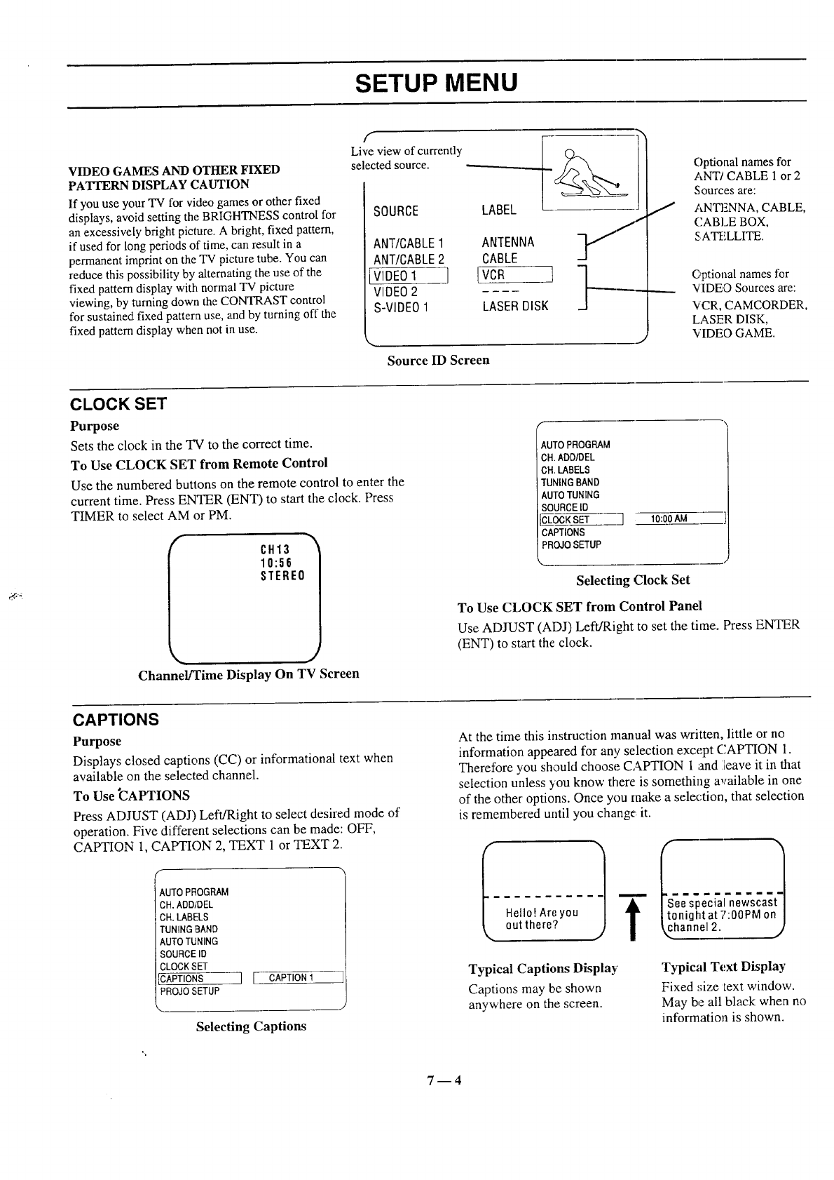
VIDEO GAMES AND OTHER FIXED
PATrERN DISPLAY CAUTION
If you use your TV for video games or other fixed
displays, avoid setting the BRIGHTNESS control for
an excessively bright picture. A bright, fixed pattern,
if used for long periods of time, can result in a
permanent imprint on the TV picture tube. You can
reduce this possibility by alternating the use of the
fixed pattern display with normal TV picture
viewing, by turning down the CONTRAST control
for sustained fixed pattern use, and by turning off the
fixed pattern display when not in use.
f
Live view of currently _
selected source.
P
SOURCE
ANT/CABLE1 ANTENNA
ANT/CABLE2 CABLE
VIDEO1 I [VCR t
VIDEO2 --,-
S-VIDEO1 LASERDISK
Source ID Screen
C)ptional names for
ANT/CABLE 1 or 2
Sources are:
ANTENNA, CABLE,
CABLE BOX,
S ATELLITE.
C,ptional names for
VIDEO Sources are:
VCR, CAMCORDER,
LASER DISK,
VIDEO GAME.
CLOCK SET
Purpose
Sets the clock in the TV to the correct time.
To Use CLOCK SET from Remote Control
Use the numbered butlons on the remote control to enter the
current time. Press ENTER (ENT) to start the clock. Press
TIMER to select AM or PM.
CH13
10:56
STEREO
J
Channel/Time Display On TV Screen
&UTO PROGRAM
CH, ADDIDEL
OH LABELS
TUNING BAND
AUTO TUNING
SOURCE ID
CLOCK SET
CAPTIONS
PROJO SETUP
]10:00AM
Selecting Clock Set
To Use CLOCK SET from Control Panel
Use ADJUST (ADJ) Left/Right to set the time. Press ENTER
(ENT) to start the clock.
CAPTIONS
Purpose
Displays closed captions (CC) or informational text when
available on the selected channel.
To Use _APTIONS
Press ADJUST (ADJ) Left/Right to select desired mode of
operation. Five different selections can be made: OFF,
CAPTION 1,CAPTION 2, TEXT 1or TEXT 2.
AUTO PROGRAM
CH. ADDIDEL
CH. LABELS
TUNING BAND
AUTO TUNING
SOURCE ID
CLOCK SET
CAPTIONS
PROJO SETUP
1 I CAPTION 1
Selecting Captions
At the time this instruction manual was written, little or no
information appeared for an,./selection except CAPTION 1.
Therefore you should choose CAPTION 1 :and :leave it in that
selection unless 2,ouknow there is something available in one
of the other options. Once you make a selection, that selection
is remembered until you change: it.
IHello! Are you
out there? Itonightat 7:00PMon I
_,_hannel2. J
Typical Captions Display
Captions may be shown
anywhere on the screen.
Typical Text Display
Fixed size text window.
May be all black when no
information is shown.
7m4
SETUP MENU
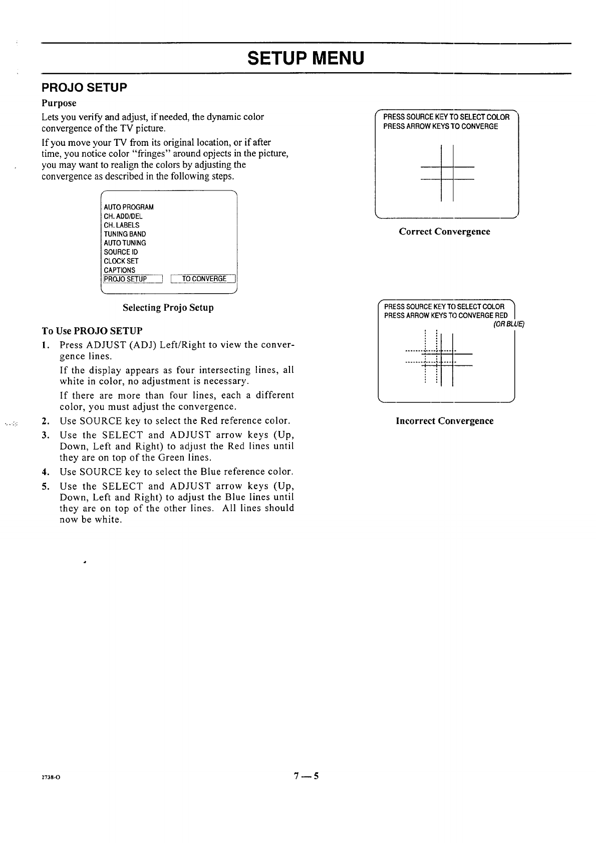
PROJO SETUP
Purpose
Lets you verify and adjust, if needed, the dynamic color
convergence of the TV picture.
If you move your TV from its original location, or if after
time, you notice color "fringes" around opjects in the picture,
you may want to realign the colors by adjusting the
convergence as described in the following steps.
AUTO PROGRAM
CH. ADD/DEL
CH. LABELS
TUNING BAND
AUTO TUNING
SOURCE ID
CLOCK SET
CAPTIONS
PROJO SETUP I [ TO CONVERGE
J
Selecting Projo Setup
To Use PROJO SETUP
1. Press ADJUST (ADJ) Left!Right to view the conver-
gence lines.
If the display appears as four intersecting lines, all
white in color, no adjustment is necessary.
If there are more than four lines, each a different
color, you must adjust the convergence.
2. Use SOURCE key to select the Red reference color.
3. Use the SELECT and ADJUST arrow keys (Up,
Down, Left and Right) to adjust the Red lines until
they are on top of the Green lines.
4. Use SOURCE key to select the Blue reference color.
5. Use the SELECT and ADJUST arrow keys (Up,
Down, Left and Right) to adjust the Blue lines until
they are on top of the other lines. All lines should
now be white.
PRESSSOURCEKEYTO SELECTCOLOR _'
PRESS ARROW KEYS TO CONVERGE
I'
Correct Convergence
PRESS SOURCE KEh'TO SELECT COLOR
PRESS ARROW KEYS TO CONVERGE RED
(OR BLUE)
Incorrect Convergence
273s-o 7-- 5
AUDIO MENU
\
RUDIrl
I BASS J
TREBLE
BALANCE
AUDIO
SEQ
SURROUND
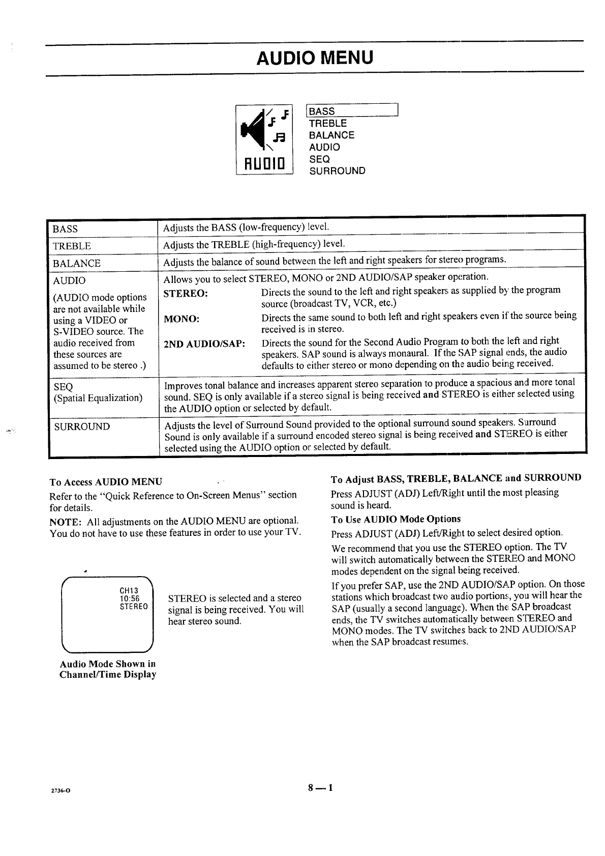
BASS
TREBLE
BALANCE
AUDIO
(AUDIO mode options
are not available while
using a VIDEO or
S-VIDEO source. The
audio received from
these sources are
assumed to be stereo .)
SEQ
(Spatial Equalization)
SURROUND
Adjusts the BASS (low-frequency) level.
Adjusts the TREBLE (high-frequency) level.
Adjusts the balance of sound between the left and right speakers for stereo programs.
Allows you to select STEREO, MONO or 2ND AUDIO/SAP speaker operation.
STEREO: Directs the sound to the left and right speakers; as supplied by the program
source (broadcast TV, VCR, etc.)
MONO: Directs the same sound to both left and right speakers even if the source being
received is in stereo.
2ND AUDIO/SAP: Directs the sound for the Second Audio Program to both the left and right
speakers. SAP sound is always monaural. Iftlhe SAP signal ends, the audio
defaults to either stereo or mono depending on the audio beirtg received.
Improves tonal balance and increases apparent stereo separation to produce a spacious and more tonal
sound. SEQ is only available ifa stereo signal is being received and STEREO is either selected using
the AUDIO option or selected by default.
Adjusts the level of Surround Sound provided to the ,optional surround sound speakers. Surround
Sound is only available if a surround encoded stereo signal is being received and STEREO is either
selected using the AUDIO option or selected by default.
To Access ,AUDIO MENU •
Refer to the "Quick Reference to On-Screen Menus" section
for details.
NOTE: All adjustments on the AUDIO MENU are optional.
You do not have to use these features in order to use your TV.
Audio Mode Shown in
Channel/Time Display
STEREO is selected and a stereo
signal is being received. You will
hear stereo sound.
To Adjust BASS, TREBLE, BALANCE and ,SURROUND
Press ADJUST (ADJ) Left/Right until the most pleasing
sound is heard.
To Use AUDIO Mode Options
Press ADJUST (ADJ) Left/Right to select desired option.
We recommend that you use the STEREO option. The TV
will switch automatically between the STEKEO and MONO
modes dependent on the signal being received.
If you prefer SAP, use the 2ND AUDIO/SAP option. On those
stations which broadcast two audio portions, you will hear the
SAP (usually a second language). When the, SAP broadcast
ends, the TV switches automatically between STEREO and
MONO modes. The TV switches back to 2ND AUDIO/SAP
when the SAP broadcast resumes.
2736-0 8_1
VIDEO MENU
UIOEO
[CONTRAST
BRIGHTNESS
COLOR
TINT
SHARPNESS
COLOR TEMP
VIDEO FILTER
AUTO FLESH
PICTURE PREF
CONTRAST Adjusts the overall contrast and color level of the pict7are.
BRIGHTNESS Adjusts the brightness level of black areas in the picture.
COLOR Adjusts the intensity of the colors in the picture.
TINT Adjusts the color of the flesh tones, where G is Green and R is Red.
SHARPNESS Adjusts the clarity of the edges of objects for the clearest picture quality.
COLOR TEMP Changes the "color temperature" or picture white balance between cooler natural whites and warmer
(red) colors.
VIDEO FILTER Reduces video "noise" or interference in dark picture areas resulting in clearer overall pictures.
AUTO FLESH Automatically maintains natural skin tones under changing scene and video source conditions.
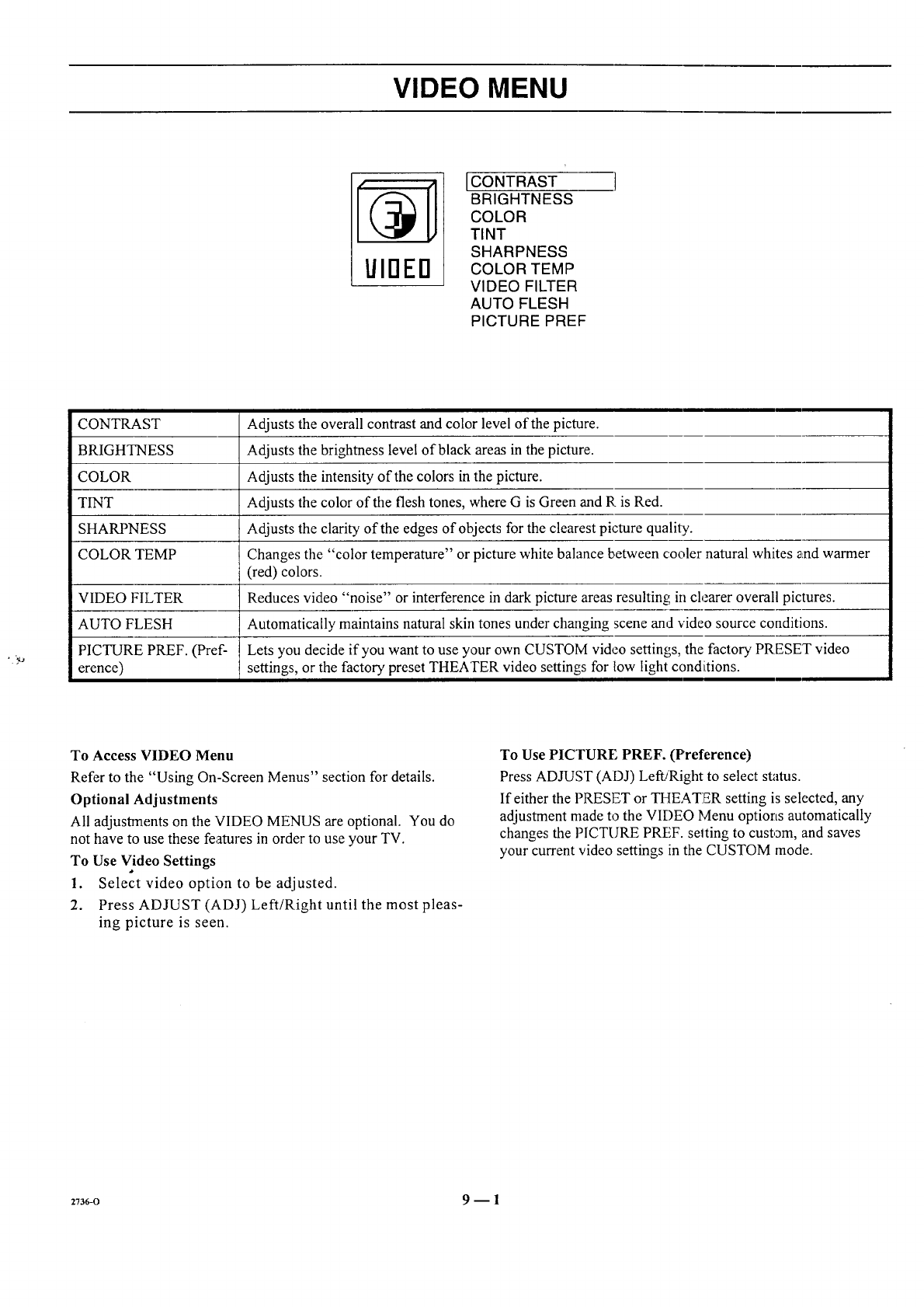
PICTURE PREF. (Pref- Lets you decide if you want to use your own CUSTOM video settings, the factory PRESET video
erence) settings, or the factory preset THEATER video settings for tow light condiitions.
To Access VIDEO Menu
Refer to the "Using On-Screen Menus" section for details.
Optional Adjustments
All adjustments on the VIDEO MENUS are optional. You do
not have to use these features in order to use your TV.
To Use Video Settings
1. Select video option to be adjusted.
2. Press ADJUST (ADJ) Left/Right until the most pleas-
ing picture is seen.
To Use PICTURE PREF. (Preference)
Press ADJUST (ADJ) Left!Right to select status.
If either the PRESET or TI-IEATER setting is selected, any
adjustment made to the VIDEO Menu options automatically
changes the PICTURE PREF. selting to custom, and saves
your current video settings in the CUSTOM mode.
z_s6-o 9 -- 1
PIP MENU
To Access PIP Menu
Refer to the "Using On-Screen
Menus" section for details.
NOTE: Selecting the PIP Menu does
not "activate" PIP. However, a PIP
inset will appear during menu
operation to show the effect of any
setting changes.
PIP
[CH. GUIDE
CH. REVIEW
PIP SOURCE
PIP COLOR
PIP TINT
PIP SIZE
] Some rnodels only
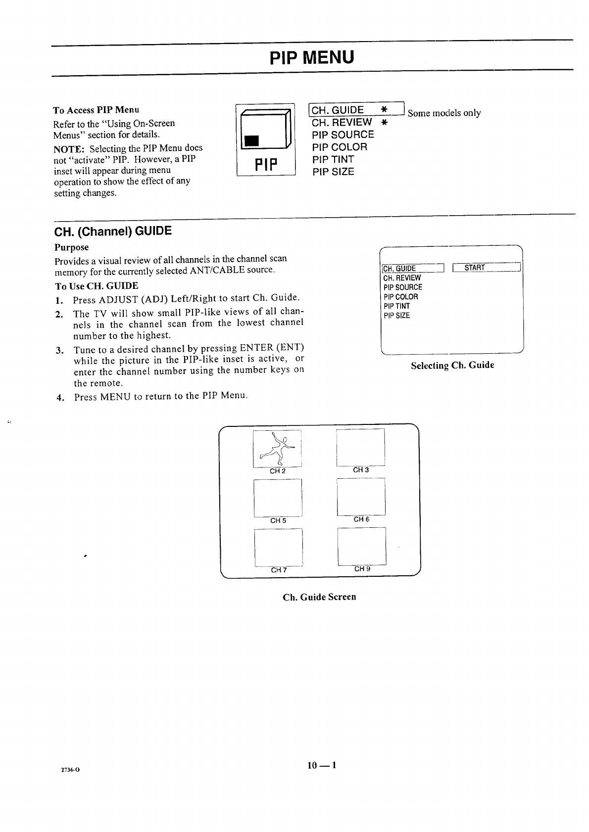
CH. (Channel) GUIDE
Purpose
Provides a visual review of all channels in the channel scan
memory for the currently selected ANT/CABLE source.
To Use CH. GUIDE
1. Press ADJUST (ADJ) Left/Right to start Ch. Guide.
2. The TV will show small PIP-like views of all chan-
nels in the channel scan from the lowest channel
number to the highest.
3. Tune to a desired channel by pressing ENTER (ENT)
while the picture in the PIP-like inset is active, or
enter the channel number using the number keys on
the remote.
4. Press MENU to return to the PIP Menu.
CH.GUIDE
CH.REVIEW
PIPSOURCE
PIPCOLOR
PIPTINT
PIPSIZE
"71 START
Selecting Ch. Guide
u
&
CH 2
CH 5
CH 7
CH 3
CH 6
iCH 9
Ch. Guide Screen
z:36-o 10 _ 1
PIP MENU
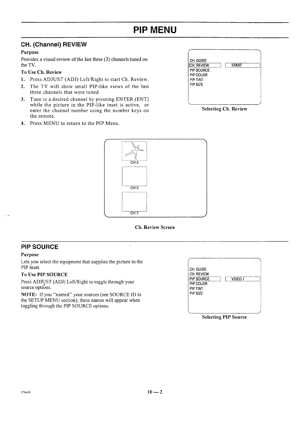
CH. (Channel) REVIEW
Purpose
Provides a visual review of the last three (3) channels tuned on
the TV.
To Use Ch. Review
1. Press ADJUST (ADJ) Left/Right to start Ch. Review.
2. The TV will show small PIP-like views of the last
three channels that were tuned.
3. Tune to a desired channel by pressing ENTER (ENT)
while the picture in the PIP-like inset is active, or
enter the channel number using the number keys on
the remote.
4. Press MENU to return to the PIP Menu.
CH. GUIDE
CH. REVIEW
PIP SOURCE
PIP COLOR
PIP TINT
PIP SIZE
IJSTART
Selecting Ch, Review
i I
CH 2
CH 5
!
CH 7
Ch. Review Screen
PIP SOURCE
Purpose
Lets you select the equipment that supplies the picture to the
PIP inset.
To Use PIP SOURCE
Press ADJUST (ADJ) Left/Right to toggle through your
source options.
NOTE: If you "named" your sources (see SOURCE ID in
the SETUP MENU section), these names will appear when
toggling through the PIP SOURCE options.
CH.GUIDE
CH.REVIEW
PIPSOURCE
PIPCOLOR
PIPTINT
PIPSIZE
]J VIDEO1
J
Selecting PIP Source
Z736-O 10--2
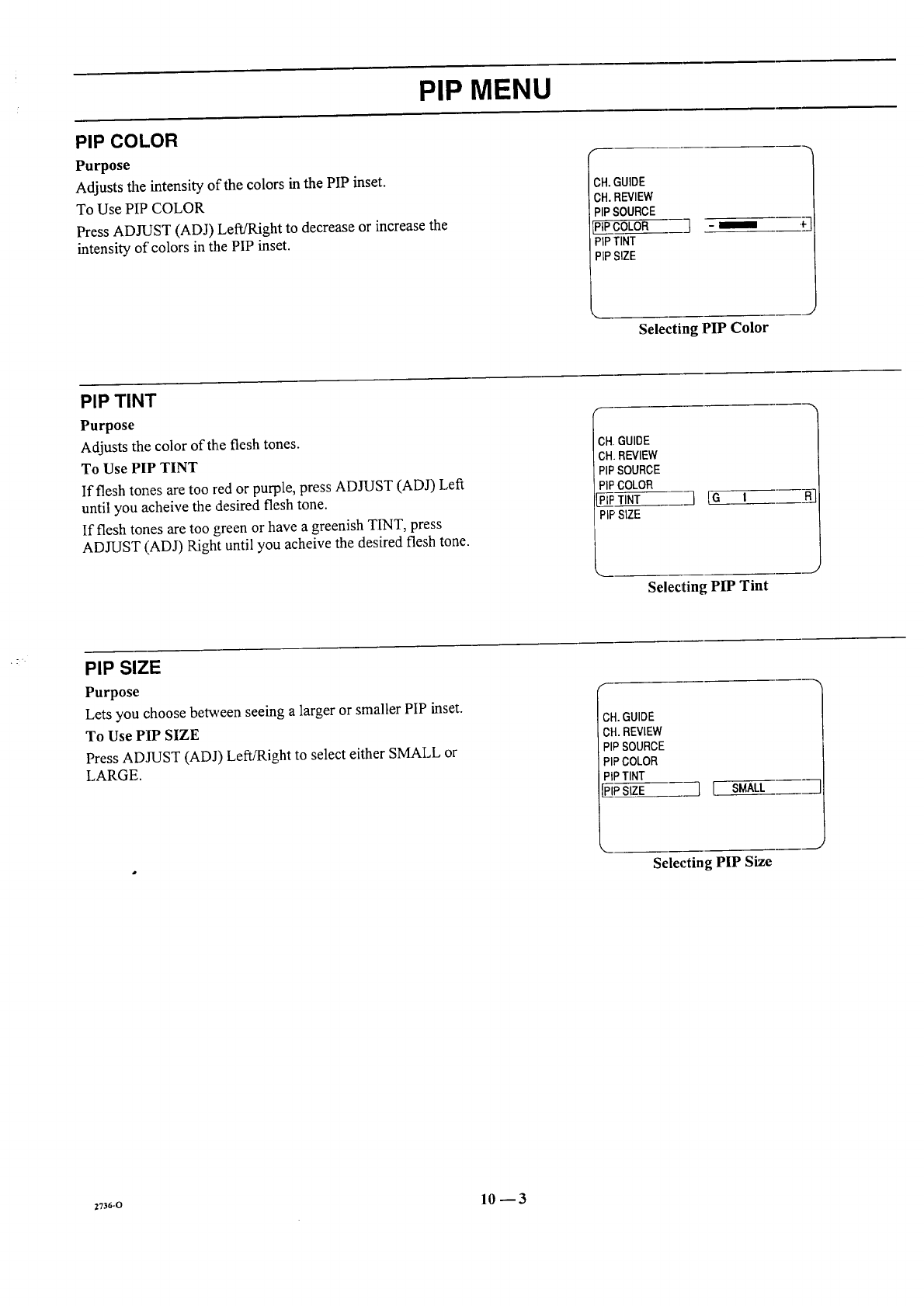
PIP MENU
PIP COLOR
Purpose
Adjusts the intensity of the colors in the PIP inset.
To Use PIP COLOR
Press ADJUST (ADJ) Left/Right to decrease or increase the
intensity of"colors in the PIP inset.
._H.GUIDE
CH.REVIEW
PIPSOURCE
PIPCOLOR
PIPTINT
PIPSIZE
] -I
Selecting PIP Color
J
PIP TINT
Purpose
Adjusts the color of the flesh tones.
To Use PIP TINT
If flesh tones are too red or purple, press ADJUST (ADJ) Left
until you acheive the desired flesh tone.
If flesh tones are too green or have a greenish TINT, press
ADJUST (ADJ) Right until you acheive the desired flesh tone.
;H, GUIDE
CH.REVIEW
PIPSOURCE
PIPCOLOR
PIPTINT
PiP SIZE ]{G t
._J
Selecting PIP Tint
PIP SIZE
Purpose
Lets you choose between seeing a larger or smaller PIP inset.
To Use PIP SIZE
Press ADJUST (ADJ) Left/Right to select either SMALL or
LARGE.
f
ICH.GUIDE
CH. REVIEW
PIPSOURCE
PIPCOLOR
PiPTINT
] [ SMALL
Selecting PIP Size
2736-0 10--3
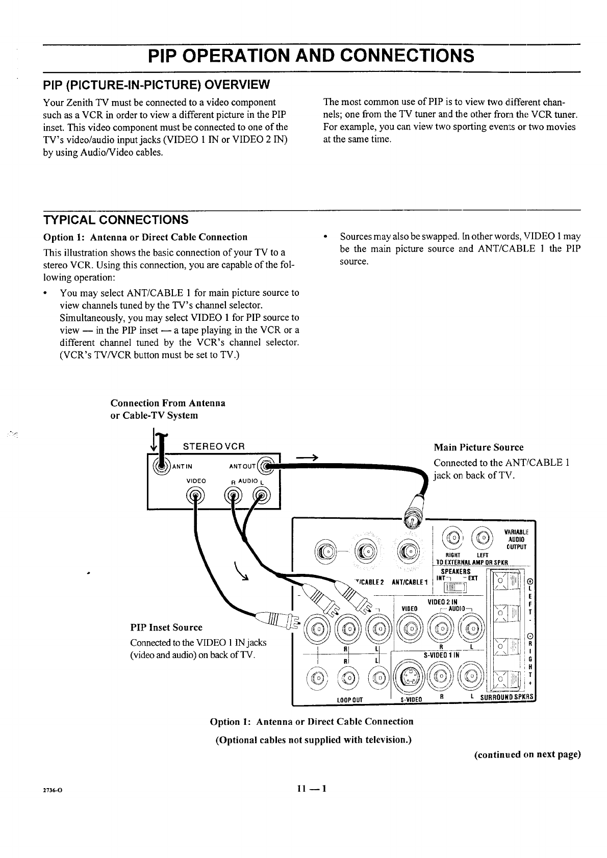
PIP OPERATION AND CONNECTIONS
PIP (PICTURE-IN-PICTURE) OVERVIEW
Your Zenith TV must be connected to a video component
such as a VCR in order to view a different picture in the PIP
inset. This video component must be connected to one of the
TV's video/audio input jacks (VIDEO 1 IN or VIDEO 2 IN)
by using Audio/Video cables.
The most common use of PIP is to view two different chan-
nels; one from the "I-9 tuner and the other frora the VCR tuner.
For example, you can view two sporting even'Is or two movies
at the same tkne.
TYPICAL CONNECTIONS
Option 1: Antenna or Direct Cable Connection
This illustration shows the basic connection of your TV to a
stereo VCR. Using this connection, you are capable of the fol-
lowing operation:
•You may select ANT/CABLE 1 for main picture source to
view channels tuned by the TV's channel selector•
Simultaneously, you may select VIDEO 1 for PIP source to
view -- in the PIP inset -- a tape playing in the VCR or a
different channel tuned by the VCR's channel selector.
(VCR's TV/VCR button must be set to TV.)
Sources may also be swapped. In other words, VIDEO 1 may
be the main picture source and ANT/CABLE 1 the PIP
SOHI'Ce.
Connection From Antenna
or Cable-TV System
Option 1: Antenna or Direct Cable Connection
(Optional cables not supplied with television.)
(continued on next page)
2736-o 11-- 1
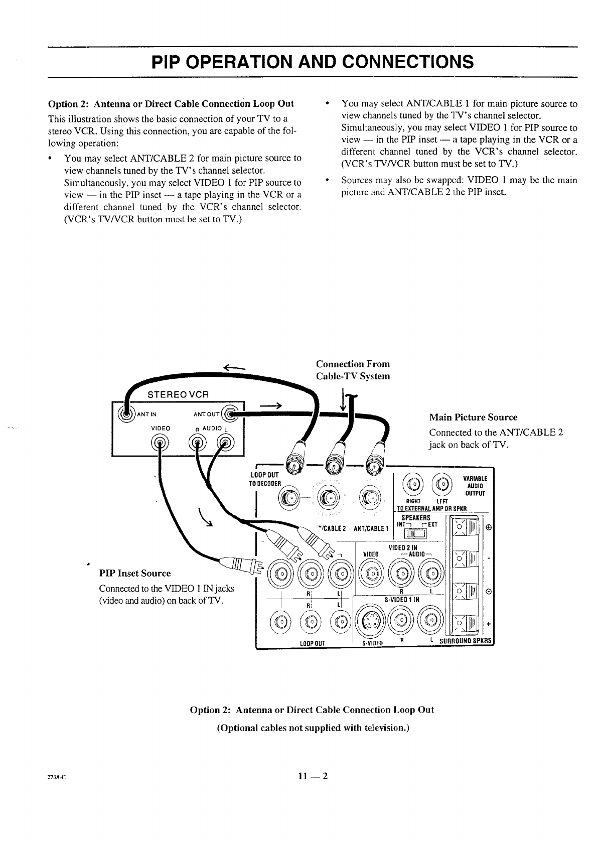
PIP OPERATION AND CONNECTIONS
Option 2: Antenna or Direct Cable Connection Loop Out
This illustration shows the basic connection of your TV to a
stereo VCR. Using this connection, you are capable of the fol-
lowing operation:
•You may select ANT/CABLE 2 for main picture source to
view channels tuned by the TV's channel selector.
Simultaneously, you may select VIDEO 1 for PIP source to
view --- in the PIP inset -- a tape playing in the VCR or a
different channel tuned by the VCR's channel selector.
(VCR's TV/VCR button must be set to TV.)
• You may select ANT/CABLE 1 for mmn picture source to
view channels tuned by the TV's channel selector.
Simultaneously, you may select VIDEO 1 for PIP source to
view -- in the PIP inset --- a tape playing in the VCR or a
differem channel tuned by the VCR's channel selector.
(VCR's TV/VCR button mu:;t be set to TV.)
• Sources may also be swapped: VIDEO 1 may be the main
picture and ANT/CABLE 2 the PIP inset.
<--... Connection From
Cable-TV System
Option 2: Antenna or Direct Cable Connection Loop Out
(Optional cables not supplied with television.)
2738.c 11-- 2
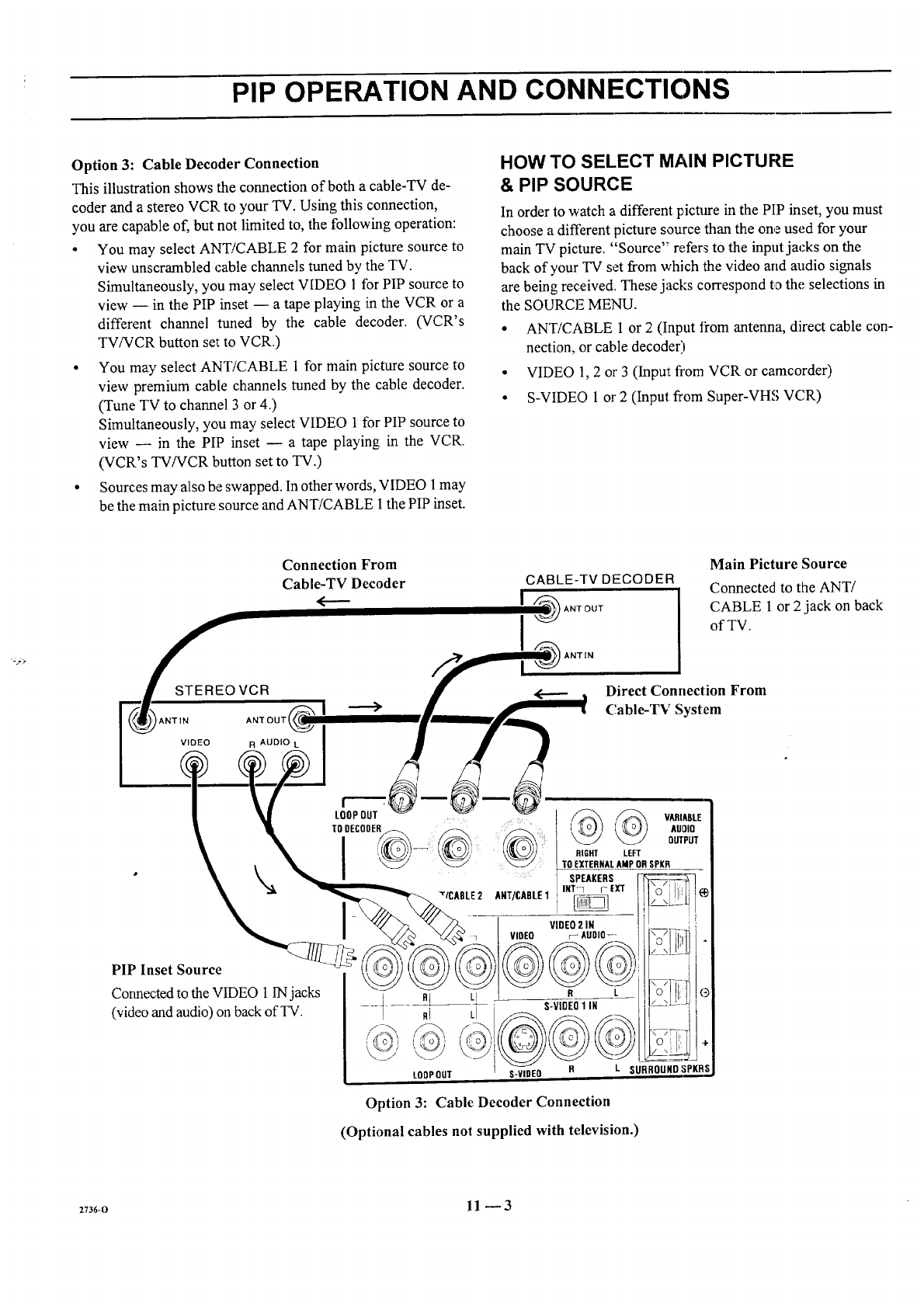
PIP OPERATION AND CONNECTIONS
Option 3: Cable Decoder Connection
This illustration shows the connection of both a cable-TV de-
coder and a stereo VCR to your TV. Using this connection,
you are capable of, but not limited to, the following operation:
•You may select ANT/CABLE 2 for main picture source to
view unscrambled cable channels tuned by the TV.
Simultaneously, you may select VIDEO 1 for PIP source to
view -- in the PIP inset -- a tape playing in the VCR or a
different channel tuned by the cable decoder. (VCR's
TV/VCR button set to VCR.)
•You may select ANT/CABLE 1 for main picture source to
view premium cable channels tuned by the cable decoder.
(Tune TV to channel 3 or 4.)
Simultaneously, you may select VIDEO 1 for PIP source to
view --- in the PIP inset -- a tape playing in the VCR.
(VCR's TV/VCR button set to TV.)
• Sources may also be swapped. In other words, VIDEO 1 may
be the main picture source and ANT/CABLE 1 the PIP inset.
HOW TO SELECT MAIN PICTURE
& PIP SOURCE
In order to watch a different picture in the PIP inset, you must
choose a different picture so_xrcethan the one used for your
main TV picture. "Source" refers to the input jacks on the
back of your TV set from which the video arid audio signals
are being received. These jacks correspond to the selections in
the SOURCE MENU.
• ANT/CABLE 1 or 2 (Input ii'om antenna, direct cable con-
nection, or cable decoder)
• VIDEO 1,2 or 3 (Input from VCR or camcorder)
• S-VIDEO 1 or 2 (Input: from Super-VHS VCR)
Option 3: Cable Decoder Connection
(Optional cables not supplied with television.)
z736-o 11 _ 3
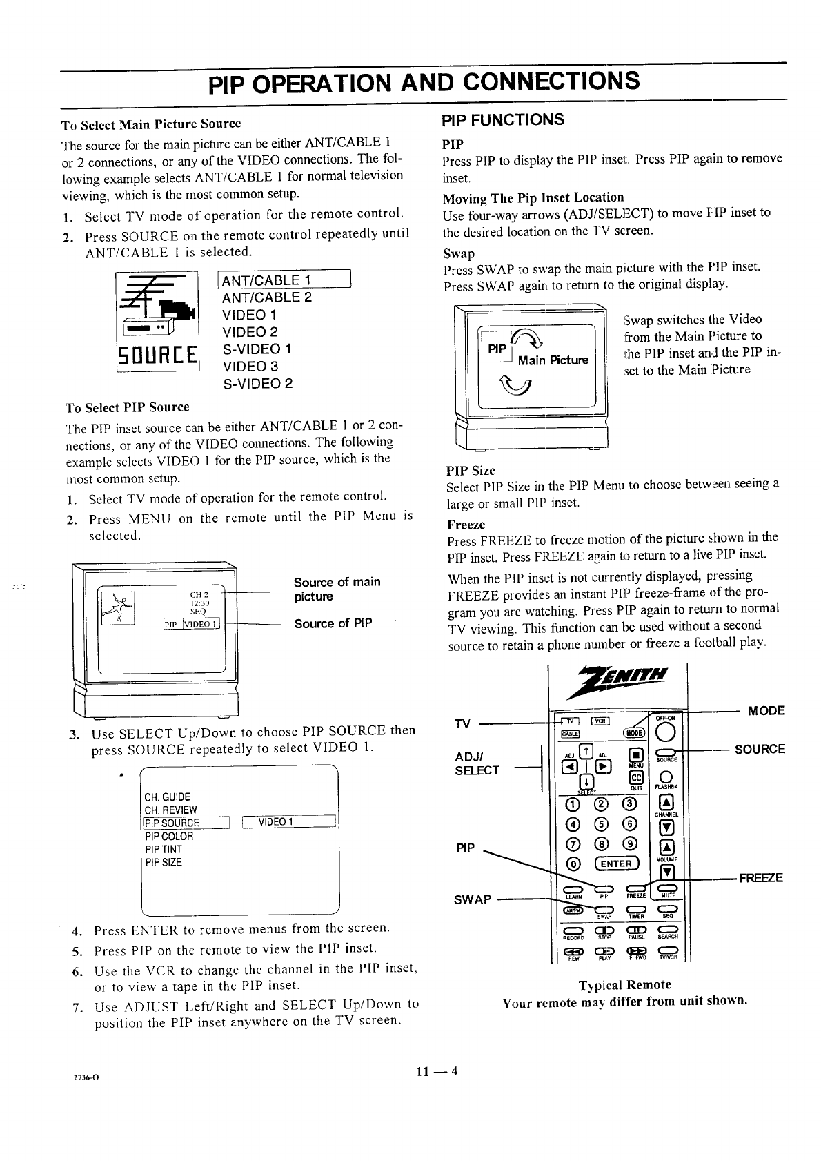
PIP OPERATION AND CONNECTIONS
To Select Main Picture Source PIP FUNCTIONS
The source for the main picture can be either ANT/CABLE 1
or 2 connections, or any of the VIDEO connections. The fol-
lowing example selects ANT/CABLE 1 for normal television
viewing, which is the most common setup.
1. Select TV mode of operation for the remote control.
2. Press SOURCE o11the remote control repeatedly until
ANT/CABLE 1 is selected.
[ANT/CABLE 1 /
ANT/CABLE 2
VIDEO 1
VIDEO 2
5I1UOEE S-VIDEO1
VIDEO 3
S-VIDEO 2
To Select PIP Source
The PIP inset source can be either ANT/CABLE 1 or 2 con-
nections, or any of the VIDEO connections. The following
example selects VIDEO [ for the PIP source, which is the
most common setup.
1. Select TV mode of operation for the remote control.
2. Press MENU on the remote until the PIP Menu is
selected.
3,
CH 2 -)
J23o /
SEQ /
IPIP ]VIDEO 1} !
Source of main
picture
Source of PIP
Use SELECT Up/Down to choose PIP SOURCE then
press SOURCE repeatedly to select VIDEO 1.
;H. GUIDE
OH. REVIEW
PiPSOURCE
PIPCOLOR
PIPTiNT
PIPSIZE
J [ VIDEO I
J
4. Press ENTER to remove menus from the screen.
5. Press PIP on the remote to view the PIP inset.
6. Use the VCR to change the channel in the PIP inset,
or to view a tape in the PIP inset.
7. Use ADJUST Left/Right and SELECT Up/Down to
position the PIP inset anywhere on the TV screen.
PIP
Press PIP to display the PIP inset. Press PIP again to remove
inset.
Moving The Pip Inset Location
Use four-way arrows (ADJ/SELECT) to move PIP inset to
the desired location on the TV screen.
Swap
Press SWAP to swap the maha picture with the PIP inset.
Press SWAP again to return to tile original display.
Swap switches the Video
from the Main Picture to
'1:hePIP inset and the PIP in-
set to the Main Picture
PIP Size
Select PIP Size in the PIP Menu to choose between seeing a
large or small PIP inset.
Freeze
Press FREEZE to freeze motion of the picture shown in the
PIP inset. Press FPd3EZE again to return to a live PIP inset.
When the PIP inset is not currently displayed, pressing
FREEZE provides an instant PIP freeze-frame of the pro-
gram you are watching. Press PIP again to return to normal
TV viewing. This function can be used without a second
source to retain a phone number or freeze a football play.
TV
ADJI ._
SELECT
PIP
SWAP
_ _1_ (_'°_F G
®@®
® @, (9
®@@ VOLUME
C:D
sw/,P 'TIMER SEQ
C:D CID CID _
R[_IX_O STCO PAUSE SEARCH
R_ PU¥ WNCR
MODE
---- SOURCE
FREEZE
Typical Remote
Your remote may differ from unit shown.
2736-0 11 -- 4
MAINTENANCE AND TROUBLESHOOTING
CARING FOR YOUR PROJECTION TV
Your projection TV will look better, have a longer life and per-
form better' if you care for it properly.
First check to see that the TV is off. For added
safety, disconnect AC power to your TV.
NOTE: If you disconnect AC power to your TV
for an extended time period, you will have to reset
the clock.
Picture Screen (,'leaning
Use asoft cloth moistened with warm water and rub lightly in
the soiled areas of the screen. DO NOT USE A TISSUE OR
PAPER TOWEL, AS THESE MAY DAMAGF SURFACE.
Wipe only in the vertical (up/dc, wn) direction (along the
grooves). If there is a dirt buildup, a mild solution of warm
water and Ivory dishwashin_, detergent may be used. Use dry
soft cloth to dry the screen. Care should be taken to avoid
scratches or damage to the screen surface.
NOTE --The TV screen is easily damaged. Avoid acciden-
tal contact with the screen.
EXTENDED ABSENCE
Before an extended absence (such as a vacation) you may
want to disconnect AC power to your TV. This will protect
the projection TV from possible damage from lightning or
power line surges. If you have an outdoor antenna, you may
also want to disconnect the antenna from the wall plate con-
nection center
NOTE: If you disconnect AC power to your q-V for an ex-
tended time period, you will have to reset the clock.
PICTURE INTERFERENCE
Your picture may be affected by interference caused by one or
a number of factors. These include:
Nearby Automobile Ignition, Electrical Appliances, etc.
Which causes a speckled, streaked picture. This is most notice-
able in weak signal areas.
Snow in Picture Caused by insufficient signal. Usually
caused by the TV being located too far from the TV station or
by an improper antenna installation.
Ghosts or Reflections Caused by signals being reflected
from surrounding buildings, water tanks, or other high struc-
tures.
Radio Signal Police, amateur or CB radio transmitters may
cause interference.
These interference problems can often be corrected through
the use of a better antenna, ,;igral amplifiers, or various filter
devices. See your TV dealer for additional information, and ac-
cessories available for your projection TV.
PROCARE2 12 -- 1
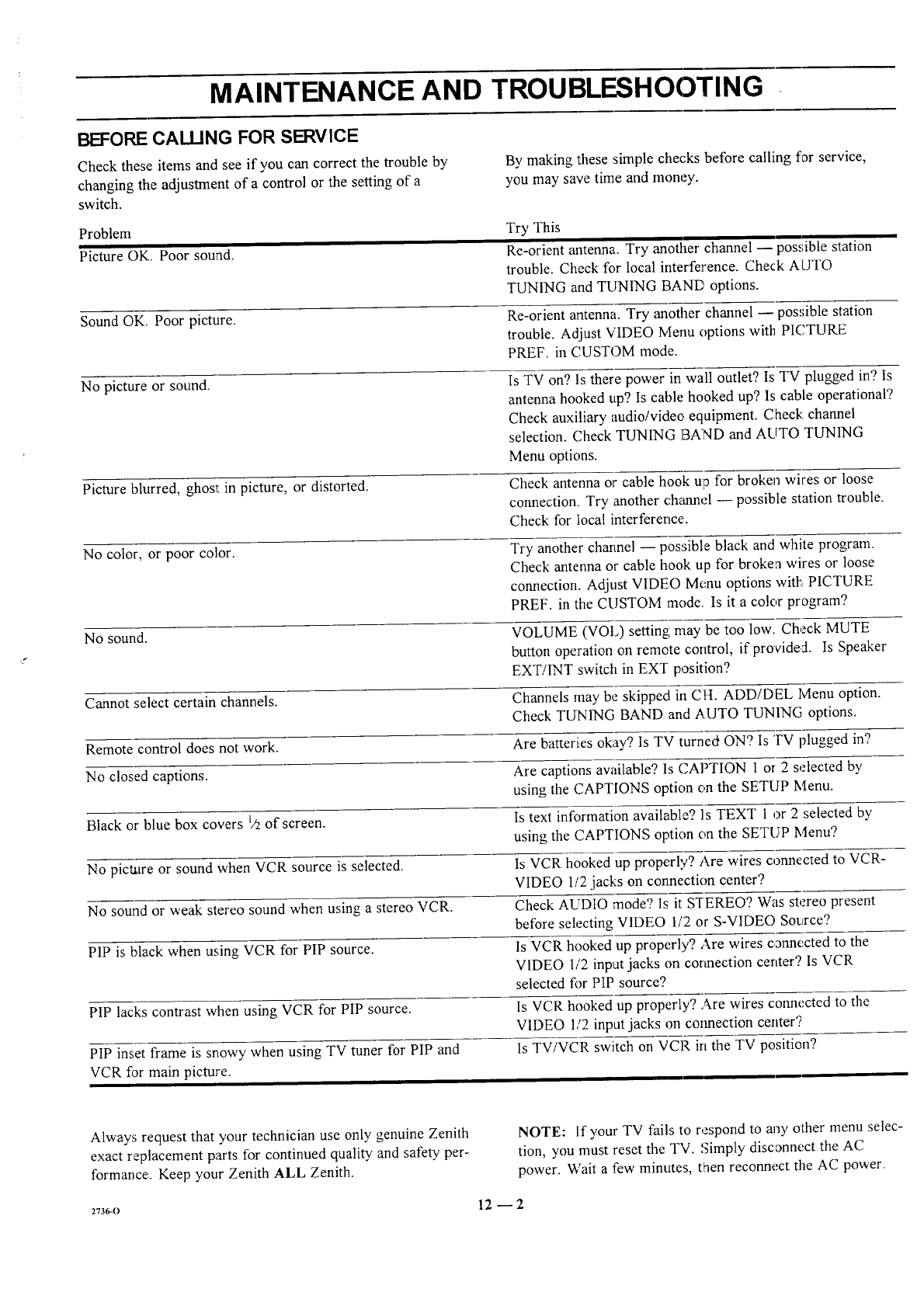
MAINTENANCE AND TROUBLESHOOTING
BEFORE CALLING FOR SERVICE
Check these items and see if you can correct the trouble by
changing the adjustment of a control or the setting of a
switch.
Problem
Picture OK. Poor sound.
Sound OK. Poor picture.
No picture or sound.
By making these simple checks before calling for service,
you may save time and money.
Try This
Re-orient antenna. Try another channel -- possible station
trouble. Check for local interference. Check AUTO
TUNING and TUNING BAND options.
Re-orient antenna. Try another channel -- possible station
trouble. Adjust VIDEO Ivlenu options with PICTURE
PREF. in CUSTOM mode.
Is TV on? ls there power in wall outlet? Is TV plugged in? Is
antenna hooked up? Is cable hooked up? Is cable operational?
Check auxiliary audio/video equipment. Check channel
selection. Check TUNING BAND and AUTO TUNING
Menu options.
Picture blurred, ghost in picture, or distorted. Check antenna or cable hook Ul3for broken wires or loose
connection. Try another ch_umel -- possible station trouble.
Check for ]local interference.
No color, or poor color. Try another charmel -- possible black and white program.
Check antenna or cable hook up for broken wires or loose
connection. Adjust VIDEO Menu options with PICTURE
PREF. in the CUSTOM mode. Is it a color program?
No sound. VOLUME (VOle) setting; may be too low. Check MUTE
button operation on remote control, if provided. Is Speaker
EXT!1NT switch in EXT position?
Cannot select certain channels. Channels may be skipped in CH. ADD/DEL Ivlenu option.
Check TUNING BAND and AUTO TUNING options.
Remote control does not work. Are batteries okay? Is TV turned ON? Is TV plugged in?
No closed captions. Are captions available? Is CAPTION 1 or 2 selected by
using the CAPTIONS option c,,nthe SETUP Menu.
Black or hlue box covers 1/2of screen. Is text information available? Is TEXT 1 or 2 selected by
using the CAPTIONS option on the SETUP Menu?
No picture or sound when VCR source is selected. Is VCR hooked up properly? Are wires connected to VCR-
VIDEO 112jacks on connection center?
No sound or weak stereo sound when using a stereo VCR. Check AUDIO mode? Is it S'rEREO? Was stereo present
before selecting VIDEO 1/2 or S-VIDEO Source?
PIP is black when using VCR for PIP source. Is VCR hooked up properly? Are wires connected to the
VIDEO 1/2 input jacks on cotmection center? Is VCR
selected for PIP source?
PIP lacks contrast when using VCR for PIP source. Is VCR hooked up properly? Are wires connected to the
VIDEO 1/2 input jacks on connection center?
PIP inset frame is snowy when using TV tuner for PIP and ls TV/VCR switch on VCR in the TV position?
VCR for main picture.
Always request that your technician use only genuine Zenith
exact replacement parts for continued qualiW and safety, per-
formance:. Keep your Zenith ALL Zenith.
NOTE: If your TV fails to respond to any other menu selec-
tion, you must reset the TV. Simply disconnect the AC
power. Wait a few minutes, then reconnect the AC power.
zv36-o 12 _ 2
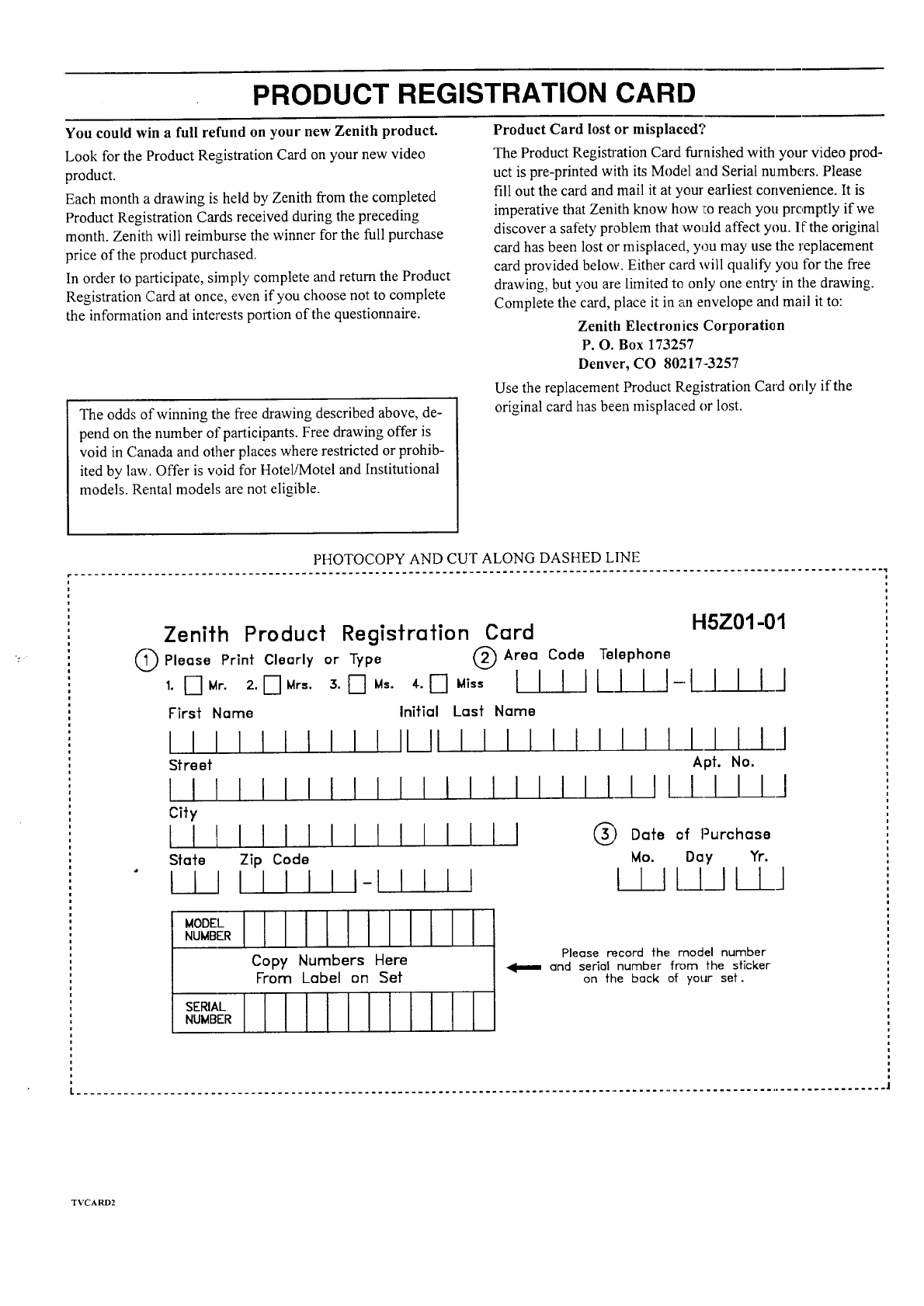
PRODUCT REGISTRATION CARl)
You could win a full refund on your new Zenith product.
Look for the Product Registration Card on your new video
product.
Each month a drawing is held by Zenith from the completed
Product Registration Cards received during the preceding
month. Zenith will reimburse the winner for the full purchase
_rice of the product purchased.
In order to participate, simply complete and return the Product
Registration Card at once, even if you choose not to complete
the information and interests portion of the questionnaire.
The odds of winning the free drawing described above, de-
pend on the number of participants. Free drawing offer is
void in Canada and other places where restricted or prohib-
ited by law. Offer is w?id for Hotel!Motel and Institutional
models. Rental models are not eligible.
Product Card lost or misplaced?
The Product Registration Card furnished with your video prod-
uct is pre-printed with its Model aad Serial numbers. Please
fill out the card and mail it at your earliest convenience. It is
imperative that Zenith know how I:o reach you promptly if we
discover a safety problem that would affect you. If the original
card has been lost or misplaced, you may use the replacement
card provided below. Either card will qualify you for the free
drawing, but you are limited to only one entry in the drawing.
Complete the card, place it in an envelope and mail it to:
Zenith Electronics Corporation
P. O. Box 173257
Denver, CO 80217-3257
Use the replacement Product Registration Card only if the
original card has been misplaced or lost.
Zenith Product Registration Card H5Z01-01
@ Please Print Clenrly or Type @ Area Code Telephone
1. [--] Mr. 2. D Mrs. 3. _] Ms. 4. D Miss I IIILIII--LI IIJ
First Name Initial Last Name
IIIIIIIIIIIIIIIIIII!IIII/I IIJ
Street Apt. No.
IIII!IIIIIIIIIIIIIIIII/_LI IIJ
City
IIIIIIIIIIIIIIII ® °°1°°__'"_°"°'°
State Zip Code Mo. Day Yr.
IIIIIIII1-1111! I I IL/_ll lJ
I I I I
Copy Numbers Here
From Label on Set
NUMBER
Please record the model number
and serial number from the sticker
on the back of your set.
I .............................................................................................................................. 1
TVCARD2
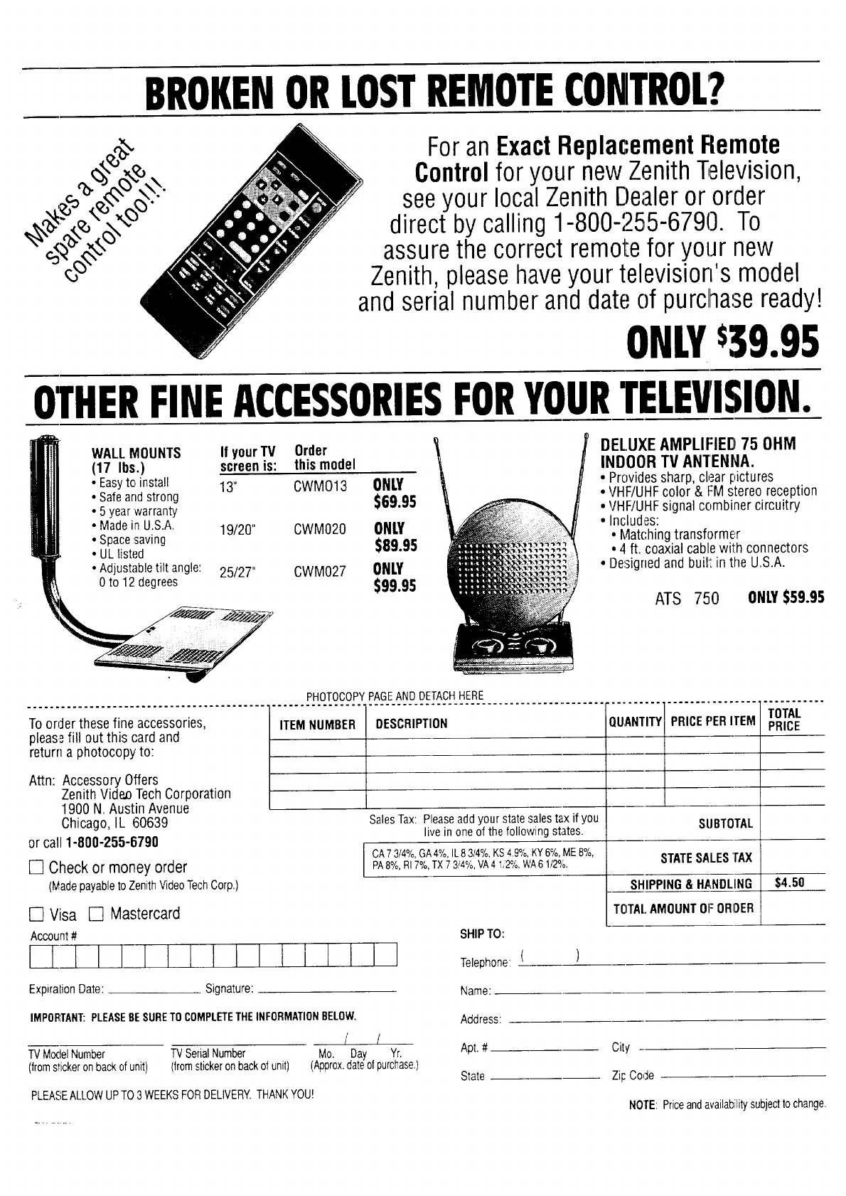
BROKENORLOSTREMOTECONTROL?
For an ExactReplacementRemote
Controlfor your new Zenith Television,
seeyour local Zenith Dealeror order
direct by calling 1-800-255-6790. To
assure the correct remote for your new
Zenith, pleasehaveyour television's model
and serial number and date of purchaseready!
ONLY$39.95
OTHERFINEACCESSORIESFORYOURTELEVISION.
WALL MOUNTS
(17 Ibs.)
• Easyto, install 13"
• Safe and strong
• 5 year warranty
• Made in U.S.A. 19/20"
• Spacesaving
• UL listed
• Adjustable tilt angle: 25/27"
0 to 12 degrees
If yourTV
screenis: Order
this model
CWMO13 ONLY
$69.95
CWM020 ONLY
$89.95
CWM027 ONLY
$99.95
DELUXEAMPLIFIED 75 OHM
INDOOR TV ANTENNA.
•Provides sharp, clear pictures
•VHF/UHF color & FM stereo reception
• VHF/UHF signal combiner circuitry
• Includes:
•Matching transformer
• 4 ft. coaxial cable with connectors
•De:signed and built in the U.S.A.
ATS 750 ONLY$59.95
To order these fine accessories,
pleasefill out this card and
return a photocopy to:
Attn: Accessory Offers
ZenithVideo TechCorporation
1900 N. Austin Avenue
Chicago, IL 60639
or call 1-800-255-6790
[] Check or money order
(Madepayableto ZenithVideoTechCorp.)
ITEM NUMBER DESCRIPTION QUANTITYI
----- i
PRICEPERITEM
Sales Tax: Please add your state sales tax if you
live in one of the following states.
TOTAL
PRICE
SUBTOTAL
CA73/4%,GA4%,fL83/4%,KS4.9%,KY6%,ME8%,
PA8%,RI7%,TX73/4%,VA41/2%_WA61/2%.
$4.50
SHIPTO:
Telephone: ( )
[] Visa [] Mastercard
Account# 1
ExpiraLionDate: Signature:
STATESALES'fAX
SHIPPING& HANDLING
TOTAl.AMOUNTOF OROER
Name:
IMPORTANT:PLEASEBESURETO COMPLETETHEINFORMATIONBELOW.
TV ModelNumber
(from stickeron back of unit)
/ /
TVSerialNumber Mo. Day Yr.
(fromstickeronbackofunit) (Approx.dateofpurchase.)
PLEASEALLOWUPTO3 WEEKSFORDELIVERY.THANKYOU!
Address:
Apt.#
State
City
ZipCode
NOrE:Priceandavailabilitysubjecttochange.
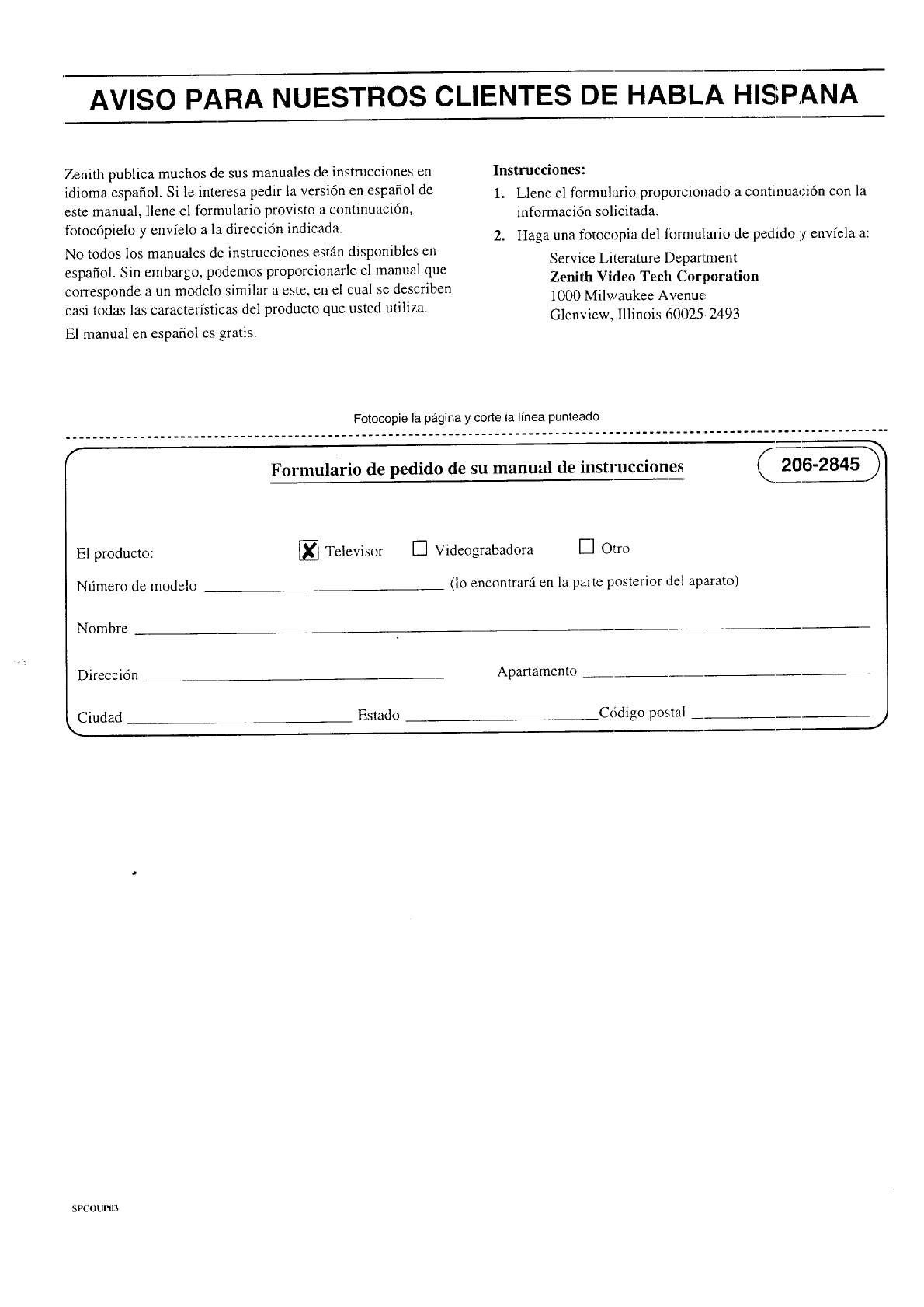
AVISO PARA NUESTROS CLIENTES DE HABLA HISPANA
Zenith publica muchos de sus manuales de instrucciones en
idioma espafiol. Si le interesa pedir la versi6n en espafiol de
este manual, llene el formulario provisto a continuacidn,
fotoc6pielo y envfelo a Ia direccidn indicada.
No todos los manuales de instrucciones est_n disponibles en
espafiol. Sin embargo, podemos proporcionarle el manual que
corresponde a un modelo similar a este, en el cual se describen
casi todas las caracterfsticas del producto que usted utiliza.
El manual en espafiol es gratis.
Instrucciones:
1. Llene el formulario proporcionado a continuaci6n con la
informaci6n solicitada.
2, Haga una fotocopia del formulario de pedido yenvfela a:
Service Literature Depar_:ment
Zenith Video Tech Corporation
1000 Milwaukee A venue
Glenview, Illinois 60025-2493
Fotocopie la pagina y corte ia Ifneapunteado
............................................................................................................................
-?
Formulario de pedido de su manual de instrucciones 206-2845
El producto:
Nfimero de modelo
[_ Televisor [] Videograbadora [] Otro
(1oencontrarfi en la parte posterior del aparato)
Nombre
Direcci6n Apartamento
Ciudad Estado C6digo postal
,. J
SPCOUPI)3
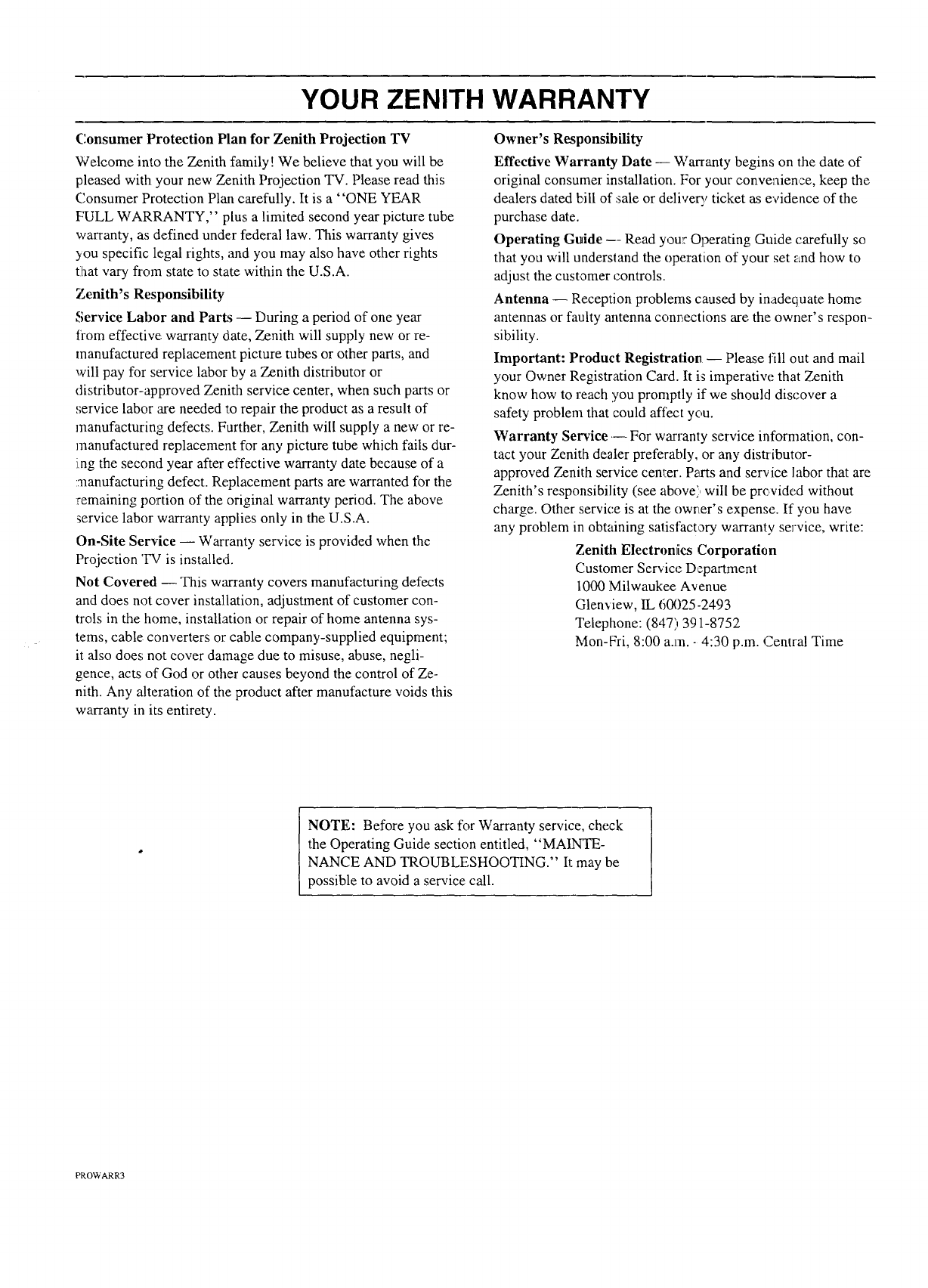
YOUR ZENITH WARRANTY
Consumer Protection Plan for Zenith Projection TV
Welcome into the Zenith family! We believe that you will be
pleased with your new Zenith Projection TV. Please read this
Consumer Protection Plan carefully. It is a "ONE YEAR
FULL WARRANTY," plus a limited second year picture tube
warranty, as defined under federal law. This warranty gives
3ou specific legal rights, and you may also have other rights
tlhat vary from state to state within the U.S.A.
7enith's ResponsibUity
Service Labor and Parts -- During a period of one year
from effective: warranty date, Zenith will supply new or re-
manufactured replacement picture tubes or other parts, and
will pay for service labor by a Zenith distributor or
distributor-approved Zenith service center, when such parts or
service labor are needed to repair the product as a result of
manufacturing defects. Further, Zenith will supply a new or re-
manufactured replacement for any picture tube which fails dur-
i,ng the second year after effective warranty date because of a
manufacturing defect. Replacement parts are warranted for the
remaining portion of the original warranty period. The above
service labor warranty applies only in the U.S.A.
On-Site Service -- Warranty service is provided when the
Projection 'IV is installed.
Not Covered. -- This warranty covers manufacturing defects
and does not cover installation, adjustment of customer con-
trols in the home, installation or repair of home antenna sys-
tems, cable converters or cable company-supplied equipment;
it also does not cover damage due to misuse, abuse, negli-
gence, acts of God or other causes beyond the control of Ze-
nith. Any alteration of the product after manufacture voids this
warranty in its entirety.
Owner's Responsibility
Effective Warranty Date -- Warranty begins on the date of
original consumer installation. [:or your convenience, keep the
dealers dated bill of sale or delivery ticket as evidence of the
purchase date.
Operating Guide --- Read your Operating Guide carefully so
that you will understand the operation of your set and how to
adjust the customer controls.
Antenna- Reception problems caused by inadequate home
antennas or faulty antenna conr_ections are the owner's respon-
sibility.
Important: Product Registration- Please fill out and mail
your Owner Registration Card. It is imperative that Zenith
know how to reach you promptly if we should discover a
safety problem that could affect you.
Warranty Service .-- For warranty service information, con-
tact your Zenith dealer preferably, or any distributor-
approved Zenith service cemer. Parts and service labor that are
Zenith's responsibility (see above) will be provided without
charge. Other service is at the owr_er's expense. If you have
any problem in obtaining satisfactory warranty service, write:
Zenith Electroniics ,Corporation
Customer Service Department
1000 Milwaukee Avenue
Glenview, IL 60025-2493
Telephone: (847)391-8752
Mon-Fri, 8:00 a.m. - 4:30 p.m. Central Time
NOTE: Before you ask for Warranty service, check
the Operating Guide section entitled, "MAINTE-
NANCE AND TROUBLESHOOTING." It may be
possible to avoid a service call.
PROWARR3

ZENITH ELECTR ONICS CORPORATION
1000 MILWAUKEE AVENUE
GLENVIEW, ILHNOIS 60025
Part No. 206-2738
Printed in U.S.A.
EP-ED
