PANASONIC LCD Television Manual L0405181
User Manual: PANASONIC PANASONIC LCD Television Manual PANASONIC LCD Television Owner's Manual, PANASONIC LCD Television installation guides
Open the PDF directly: View PDF ![]() .
.
Page Count: 52
Panasonic
LCD TV
Operating Instructions
Model No,
For assistance, please call : %800o21%PANA (7262)
or send eoraaH to : consumerpreducts@panasonBc.com
or vUsit us at www.panasonBc.com (U.S.A.}
For assistance, pmease call : 787-750-4300
or vUsUtus at www.panasonBc.com (Puerto Rico}
For assistance, pmease call : 1-800-561 °5505
or visit us at www.panasonic.ca (Canada)
Before connecting, operating or adjusting this product, please read these instructions completely.
Please keep this manual for future reference,
/ EspaSoJ-) [Resumen] TQBOOZSt
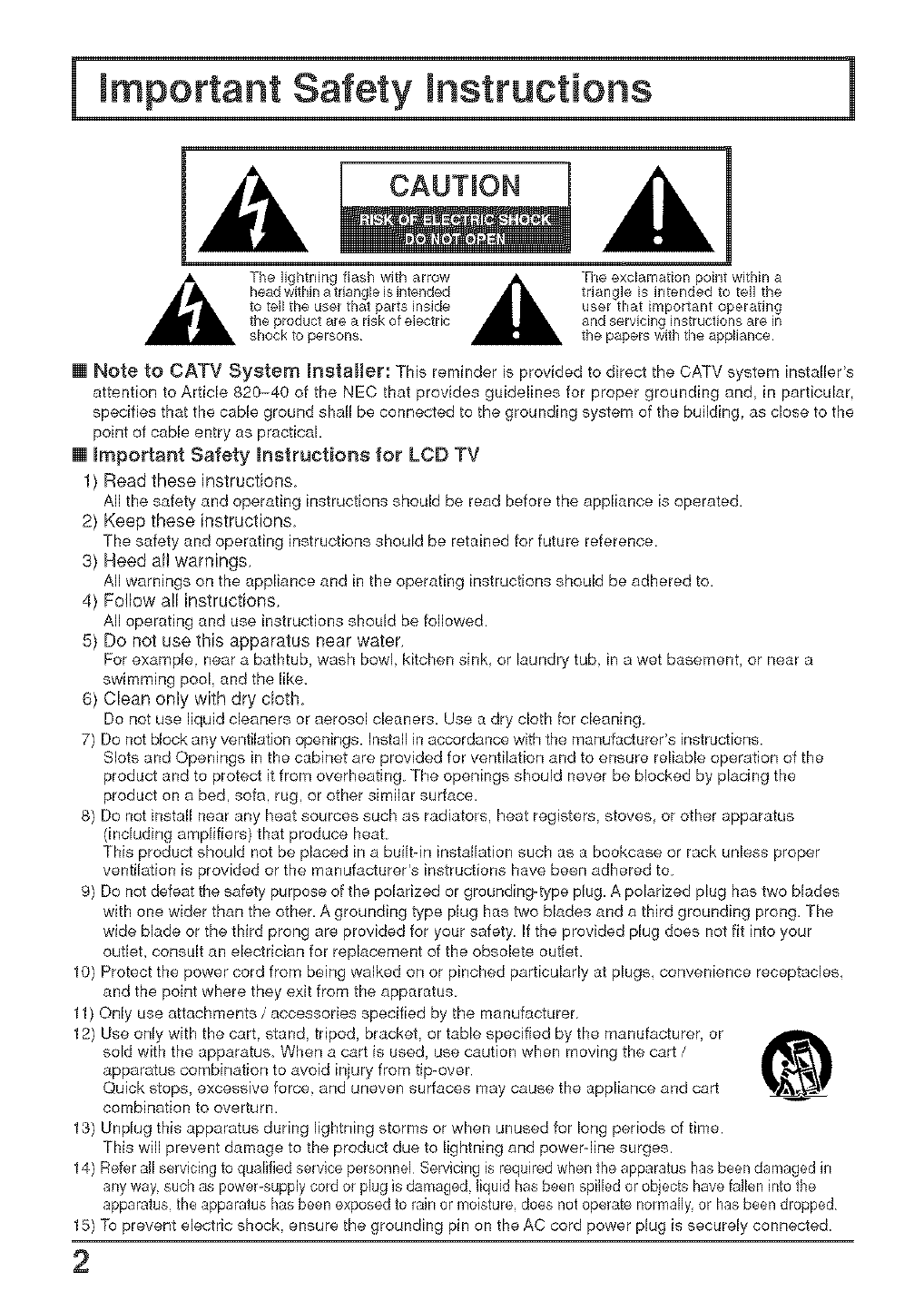
CAUTmON
A The lightning flash with arrow A The exclamation point wkMn a
head within a triangle isintended _ triangle is intended to tell the
to tell the user that parts inside
the product are a risk of electdc
shock to persons
[] Note to CATV System mnstaEler: This reminder is provided to direct the CATV system installer's
attention to Article 820-40 of the NEC that provides guidelines for proper grounding and, in particular,
specifies that the cable ground shall be connected to the grounding system of the building, as close to the
point of cable entry as practical.
[] Important Safety instructions for LCD TV
1) Read these instructions.
All the safety and operating instructions should be read before the appliance is operated,
2) Keep these instructions
The safety and operating instructions should be retained for future reference.
3) Heed all warnings.
All warnings on the appliance and in the operating instructions should be adhered to,
4) Follow all instructions.
All operating and use instructions should be followed.
5) Do not use this apparatus near water.
For example, near a bathtub, wash bowl kitchen sink. or laundry tub. in a wet basement, or near a
swimming pool, and the like.
6) Clean only with dry cloth
Do not use liquid cleaners or aerosol cleaners, Use a dry cloth for cleaning.
7) Do not block any ventilation openings. Install in accordance with the manufacturer's instructions.
Slots and Openings in the cabinet are provided for ventilation and to ensure reliable operation of the
product and to protect it from overheating. The openings should never be blocked by placing the
product on a bed, sofa. rug, or other similar surface.
8) Do not install near any heat sources such as radiators, heat registers, stoves, or other apparatus
(including amplifiers) that produce heat.
This product should not be placed in a built-in installation such as a bookcase or rack unless proper
ventilation is provided or the manufacturer's instructions have been adhered to.
9) Do not defeat the safety purpose of the polarized or grounding-type plug. A polarized plug has two blades
with one wider than the other, A grounding type plug has two blades and a third grounding prong, The
wide blade or the third prong are provided for your safety. If the provided plug does not fit into your
outlet, consult an electrician for replacement of the obsolete outlet.
10) Protect the power cord from being walked on or pinched particularly at plugs convenience receptacles.
and the point where they exit from the apparatus.
11) Only use attachments /accessories specified by the manufacturer.
12) Use only with the cart. stand, tripod, bracket, or table specified by the manufacturer, or
sold with the apparatus. When a cart is used, use caution when moving the cart /
apparatus combination to avoid injury from tip-over.
Quick stops, excessive force, and uneven surfaces may cause the appliance and cart
combination to overturn.
13) Unplug this apparatus during lightning storms or when unused for long periods of time.
This will prevent damage to the producl due to lightning and power-line surges.
14) Refer all servicing to qualified service personnel Servicing is required when the apparatus has been damaged in
any way, such as power-supply cord or plug is damaged, liquid has been spilled or objects have fallen into the
apparatus, the apparatus has been exposed to rain or moisture, does not operate normally, or has been dropped
15) To prevent electric shock, ensure the grounding pin on the AC cord power plug is securely connected
2
important Safety instructions
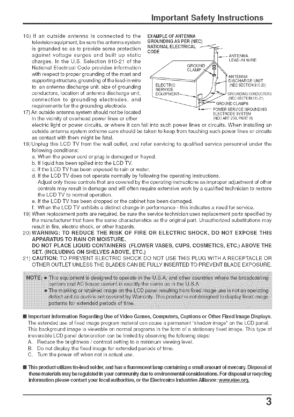
18) If an outside antenna is connected to the EXA_,_PLEOFANTENNA
television equipment, be sure the antenna system GROUNDINGA£ PER(_'_EO)
is grounded so as to provide some protection
against voltage surges and built up static
charges In the US. Selection 810-21 of the
National Electrical Code provides information
with respect to proper grounding of the mast and
supporting structure grounding of the lead-in wire
to an antenna discharge unit, size of grounding
conductors, location of antenna discharge unit,
connection to grounding electrodes, and
requirements for the grounding electrode.
17) An outside antenna system should not be located ELECTRODESYSTEM
in the vicinity of overhead power lines or other (NECART250,PARTH)
electric light or power circuits, or where it can fall into such power lines or circuits. When installing an
outside antenna system extreme care should be taken to keep from touching such power lines or circuits
as contact with them might be fatal,
18)Unplug this LCD TV from the wall outlet, and refer servicing to qualified service personnel under the
following conditions:
a When the power cord or plug is damaged or frayed
b If liquid has been spilled into the LCD TV.
c If the LCD TV has been exposed to rain or water.
d, If the LCD TV does not operate normally by following the operating instructions.
Adjust only those controls that are covered by the operating instructions as improper adjustment of other
controls may result in damage and wB often require extensive work by a qualified technician to restore
the LCD TV to normal operation.
e If the LCD TV has been dropped or the cabinet has been damaged,
f. When the LCD TV exhibits a distinct change in performance - this indicates a need for service
19) When replacement parts are required, be sure the service technician uses replacement parts specified by
the manufacturer that have the same characteristics as the original part. Unauthorized substitutions may
result in fire, electric shock, or other hazards
20)WARNHG: TO REDUCE THE RISK OF FIRE OR ELECTRIC SHOCK, DO NOT EXPOSE THIS
APPARATUS TO RAIN OR MOISTURE.
DO NOT PLACE LIQUID CONTAINERS (FLOWER VASES, CUPS, COS[vIETIOS, ETC.} ABOVE THE
SET. (INCLUDING ON SHELVES ABOVE, ETC,)
21) CAUTION: TO PREVENT ELECTRIC SHOCK DO NOT USE THIS PLUG WITH A RECEPTACLE OR
OTHER OUTLET UNLESS THE BLADES CAN BE FULLY INSERTED TO PREVENT BLADE EXPOSURE,
! Hmpou'tanfrHnfm'maBm_Regarding Use of Video Games, Computm's, Capfriose m' Other Fixed HmageDispHays.
The extended use of fixed image program material can cause a permanent "shadow image" on the LCD panel,
This beckground image is viewable oR normal programs in the form of a stationary fixed image, This type of
irreversible LCD panel deterioration can be limited by observing the following steps:
A. Reduce tbe brightness /contrast setting to a minimum viewing level.
B. Do not display the fixed image for extended periods of time.
C. Turn the power off when not in actual use.
! This product utilizse tiu_-lsedselbeu',and has a fllnm'seueu_tlamp eou_taiu_inga small amount of mercury. Disposal of
these materials may be rsgula_;d in your community due Nosnviromnsntal coseidemfrioue. Fro'disposal or reDycling
iu_fm'matim_please contact your flocaflauthm'itise, m' the EIsetrm_iue h_duetu'iseAflHiance:www.sise.org_
3

Dear Panasonie Customer
Welcome to the Pa_asol_ic family of eustomers_
We hope that you will have many years of enjoyment /?om your new LCD T_
To obtain maximum be_csfit from your set, please read these instructions before
mahi_g alzy adjustments, a_zd retai_ them S_r f_¢ture ref_renee_
Retain your purchase receipt, and record the model number and serial _umber
of your set in the space provided on the rear cover of these i_structions.
For assistance, please call : 1-800-211oPANA (7262)
o_ send e-mail to : consurnerproducts@panasonie,com
or visit us at www, panasonic,eom (U.S,A,)
For assistance, please call : 787°750°4300
or visit us at www.panasonie.eom (Puerto Rico)
For assistance, pmease call : 1o800-561o5505
or visit us at www.panasonic.ea (Canada)
Federal Communication Commission Information ]
This equipment has been tested and found to comply with the limits for a TV Broadcast Receiver, pursuant
to Part 15 of the FCC Rules. These limits are designed to provide reasonable protection against harmful
interference in a residential installation. This equipment generates, uses and can radiate radio frequency
energy and, if not installed and used in accordance with the instructions, may cause harmful interference to
radio communications. However, there is no guarantee that interference will not occur in a particular
installation If this equipment does cause or receive interference, which can be determined by turning
equipment off and on, the user is encouraged to try to correct the interference by one or more of the
following measures:
Reorient or relocate the TV antenna,
Increase the separation between TV and other equipment
Connect TV into separate outlet from other equipment
Consult the dealer or an experienced radio /TV technician for help.
FCC Caution: Pursuant to 47CFR, Part 15.21 of the FCC rules, any changes or modifications not expressly
approved by Matsushita Electric Corporation of America could result in harmful interference and would void
the user's authority to operate this equipment,
The Energy Star label, a symbol for energy efficiency, was created by the US
Environmental Protection Agency (EPA) and the U.S. Department of Energy
(DOE) to help customers identify products that can save them money and protect
the environment by saving energy. Energy Star compliant products generally
consume less energy than similar standard products.
HDMI, the HDMI logo and High-Definition Multimedia Interface
are trademarks or registered trademarks of HDMI Licensing LLC,
HI@H-DEFUNITUON M ULTIME_IA UNTERFACE
4
Important Safety h_structions .............................. 2
SUPPLIED ACCESSORIES ................................... 5
h_stallation ............................................................. 6
Corlrlectiorls .......................................................... 7
Antenna Connection ..................................... 7
Cable Box Connection ................................... 8
Connecting Other Equipment ..................... 9
Connecting Headphones/Earphones ............... 10
HDMI Connection 11
Basic Conlrols ..................................................... 12
Remote Control ................................................. 12
Main Unit 14
Power ON /OFF ...................................................14
ASPECT Controls ................................................ 15
Photo ViewerTM ....................................................16
Thumbnail Mode ........................................ 17
Photo Viewer TM Setup Menu 18
Menu Operations .................................................20
Tuning Channels ........................................... 22
LOCK .............................................. 24
CLOSED CAPTION .................................. 27
INPUT LABEL .................................... 28
OTHER ADJUST ....................................... 28
PICTURE ADJUST ..................................... 29
POSITION/SIZE 31
AUDIO ADJUST 32
Operating peripheral equipment using
the remote control ............................................ 33
Programming the remote control code ......... 33
Infrared Code Index 34
Mode Operational Key Chart 37
=Manual de instrucciones [ Resumen ]--
h_stalaci6n de las pHas
del mando a distancia ................................. 39
Conexion ........................................................40
Conexi6n de antena ........................... 40
Conexi6n del receptor de TV por cable .... 41
Controles basicos ......................................... 42
Control remoto iluminado ....................... 42
Aparato principal 44
Cone×i6n /desconexi6n de HaaHimeu_taci6n ... 44
Photo Viewer TM .............................................. 45
Modo de imagen miniatura 45
Oper_oiones COrl133enus .............................. 46
SintonizaciSn de canales ...................... 48
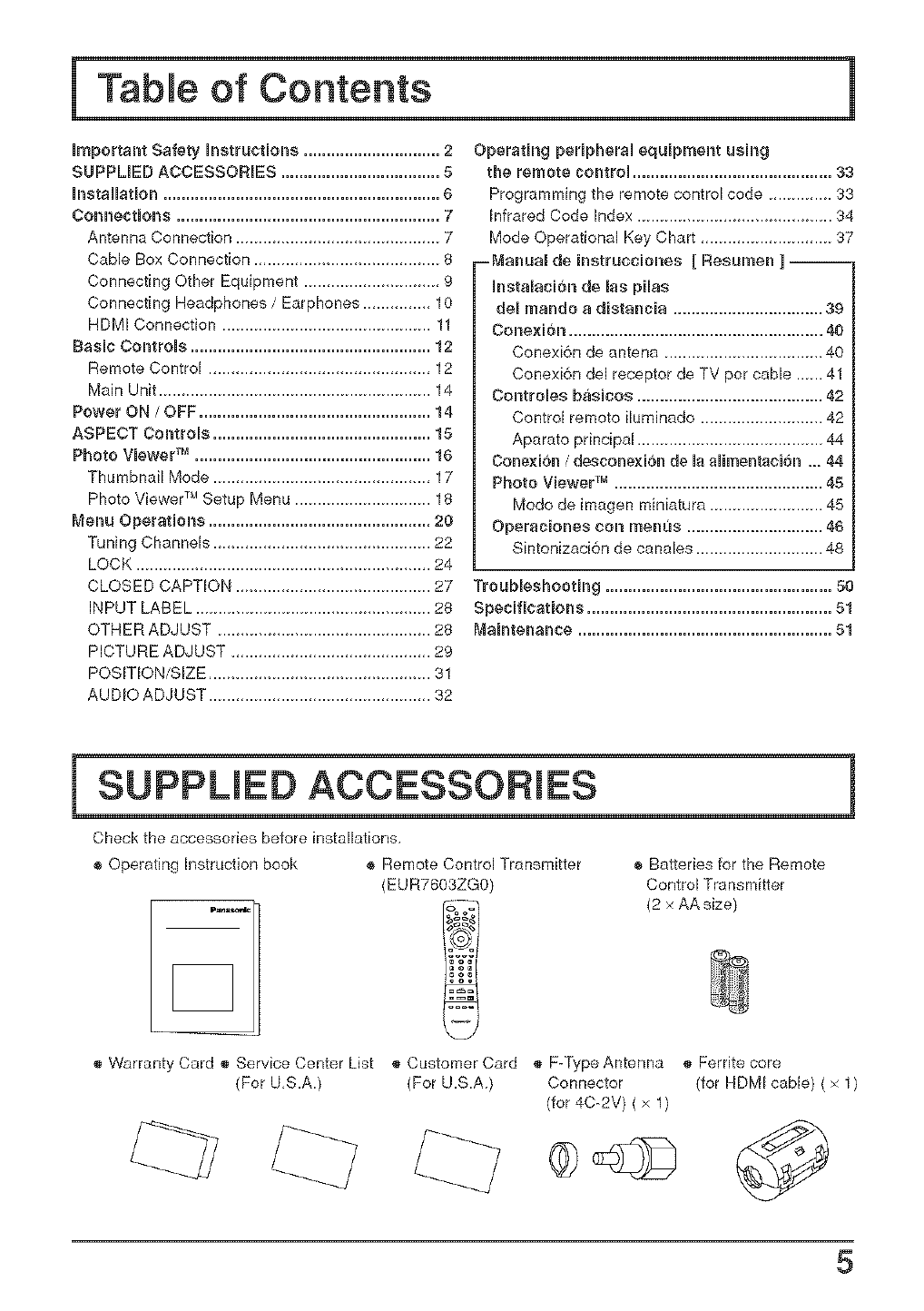
SUPPUED ACCESSORIES
Check the accessories before installations,
® Operating instruction book ® Remote Control Transmitter ® Balteries for the Remote
(EUR7603ZG0) Control Transmitter
.... &_,_ (2 x AA size)
® Warranty Card ® Service Center List ® Customer Card ® F-Type Antenna ® Ferrite core
(For U,S.A.) (For U.S.A ) Connector
(for4O-2V) (x 1)
(for HDMI cable) ( × 1)
5
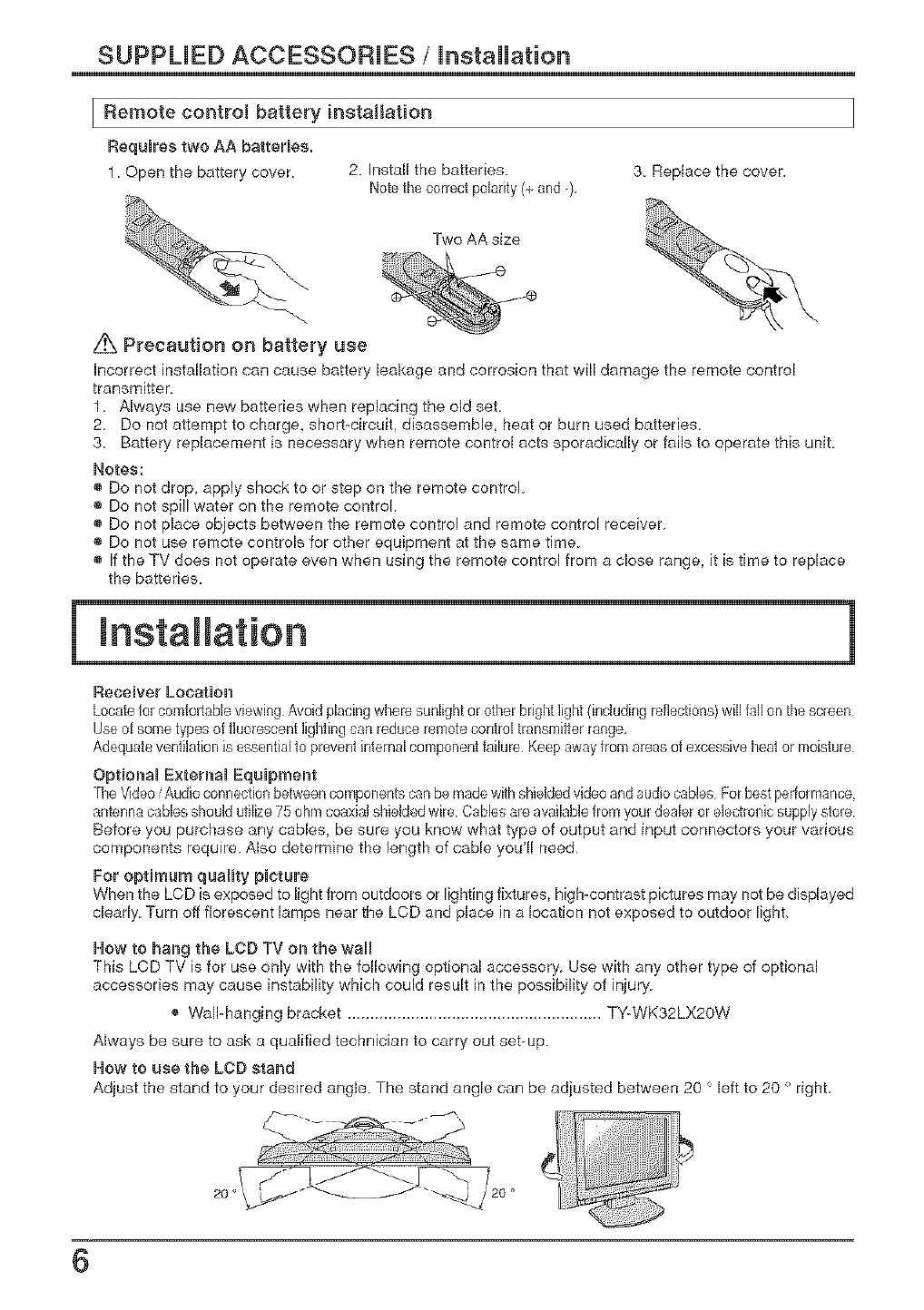
SUPPLIED ACCESSORIES /installation
IF{emote controt battery installation
Requires two AA batteries=
1. Open the buttery cover. 2. Install the batteries
Notethecorrect poladty (+ and -), 3 Replace the cover.
Two AA size
z_ Precaution on battery use
Incorrect installation can cause battery leakage and corrosion that will damage the remote control
transmitter.
1. Always use new batteries when replacing the old set.
2. Do not altempt to charge, short-circuit, disassemble, heat or burn used batteries.
3. Battery replacement is necessary when remote control acts sporadically or fails to operate this unit.
Notes:
® Do not drop, apply shock to or step on the remote control
® Do not spill water on the remote control.
Do not place objects between the remote control and remote control receiver
® Do not use remote controls for other equipment at the same time
® If the TV does not operate even when using the remote control from a close range,
the batteries. it is time to replace
Receiver Location
Locatefor comfortableviewing Avoid phcing where sunlightor other brightlight (induding reflections}will fall on the screen
Use of sometypes of fluorescentlightingcan reduce remote control transmitterrange,
Adequateventilationis essentialto preventinternalcomponent failure Keep awayfrom areasof excessiveheator moisture
Optional External Equipment
TheVideo/Audio connectionbetweencomponentscanbemadewith shieldedvideoandaudio cables Forbestperformance
antennacablesshould utilize 75 ohm coaxialshieldedwire. Cablesare availablefrom yourdealer or electronicsupplystore
Before you purchase any cables, be sure you know what type of output and input connectors your various
components require Also determine the length of cable you'll need,
For optimum quality picture
When the LCD is exposed to light from outdoors or lighting fixtures, high-contrast pictures may not be displayed
clearly Turn off florescent lamps near the LCD and place in a location not exposed to outdoor light,
How to hang the LeD TV on the wal
This LCD TV is for use only with the following optional accessory Use with any other type of optional
accessories may cause instability which could result in the possibility of injury
_, Wall-hanging bracket TY-WK32LX20W
Always be sure to ask a qualified technician to carry out set-up
How to use the LCD stand
Adjust the stand to your desired angle. The stand angle can be adjusted between 20 < left to 20 ' right,
6
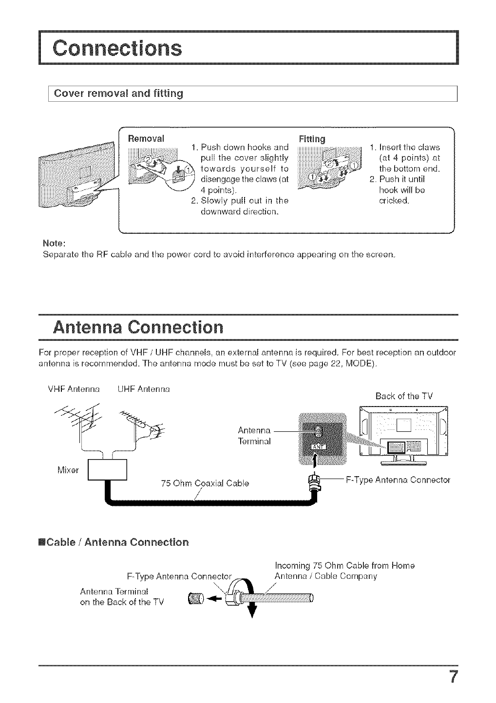
Cover removal and fitting
Removal FBtth_g
1. Push down books and
pu,thecoversUgh,y ,-'_" /
iiiiiiiiiiiiiiii_ii_2_
_ _:_ towardsyourselfto
_Jdisengagetheclaws(at
\_" 4 points).
2. Slowly pull out in the
downward direction,
1 Insert the claws
(at 4 points) at
the bottom end.
2. Push it until
hook will be
cricked
Note:
Separate the RF cable and the power cord to avoid interference appearing on the screen.
Antenna Connection
For proper reception of VHF /UHF channels, an external antenna is required For best reception an outdoor
antenna is recommended. The antenna mode must be set to TV (see page 22. MODE)
VHF Antenna UHF Antenna
Mixer
Antenna
Terminal
75 Ohm Coaxial Cable
Back of the TV
9e Antenna Connector
mCabJe /Antenna Connection
F-Type Antenna Connector
Antenna Terminal \
on the Back of the TV
Incoming 75 Ohm Cable from Home
Antenna /Cable Company
/
7
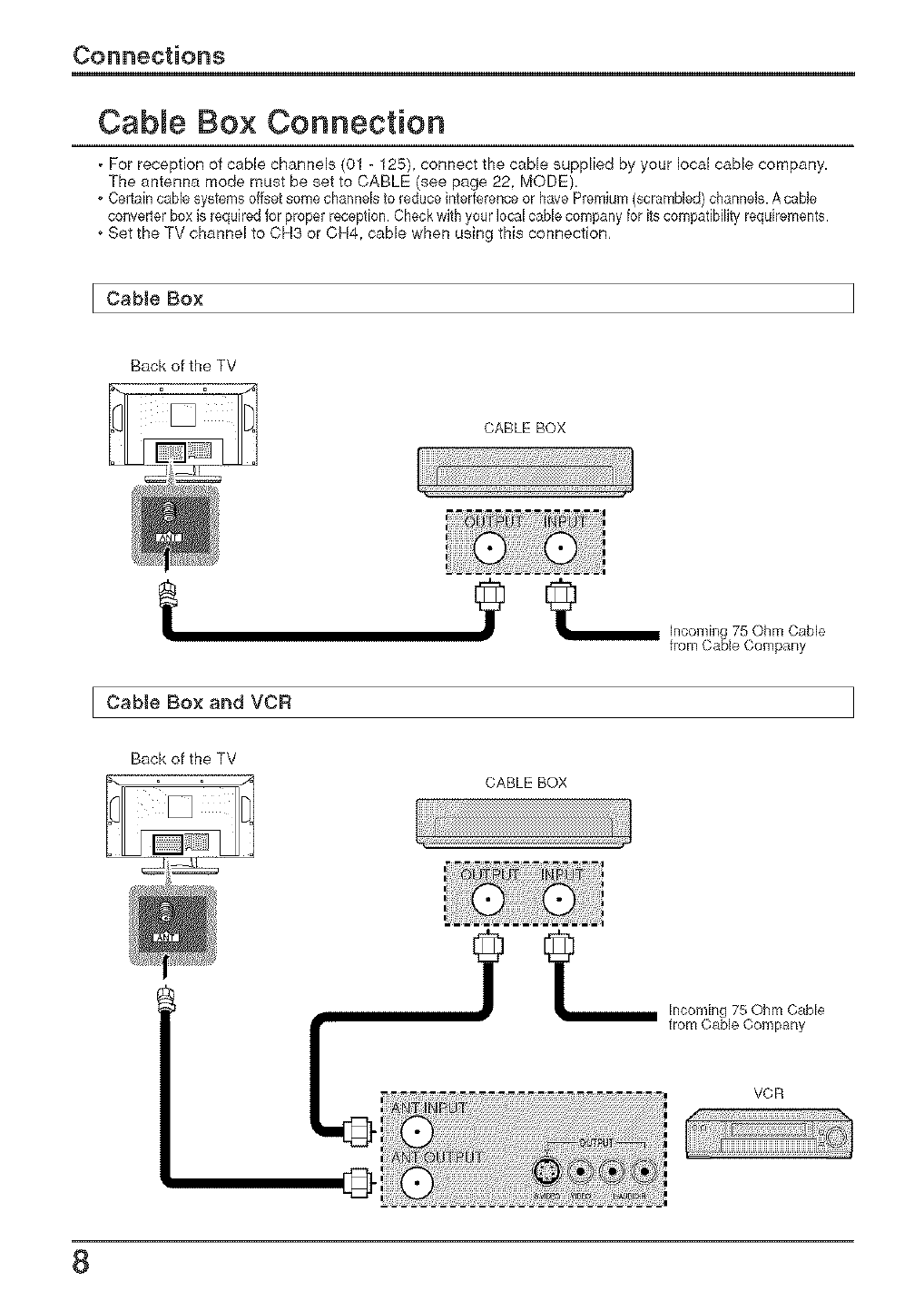
Cable Box Connection
, For reception of came channels (01 - 125), connect the cable supplied by your local came company.
The antenna mode must be set to CABLE (see page 22. MODE)
o Certaincablesystems offsetsome channelsto reduceinterferenceor have Premium(scrambled)channels.A cable
converter boxis requiredfor properreception.Checkwith your local cablecompany for itscompatibilityrequkements.
o Set the TV channel to CH3 or CH4. came when using this connection,
I Cable Box
Back of the TV
CABLE BOX
t
Cable Box and VCR
_ [nconflng 75 Ohm Cable
from Cable Company
Back of the TV
CABLE BOX
Incoming 75 Ohm Cable
from Cable Company
VCR
[D
8
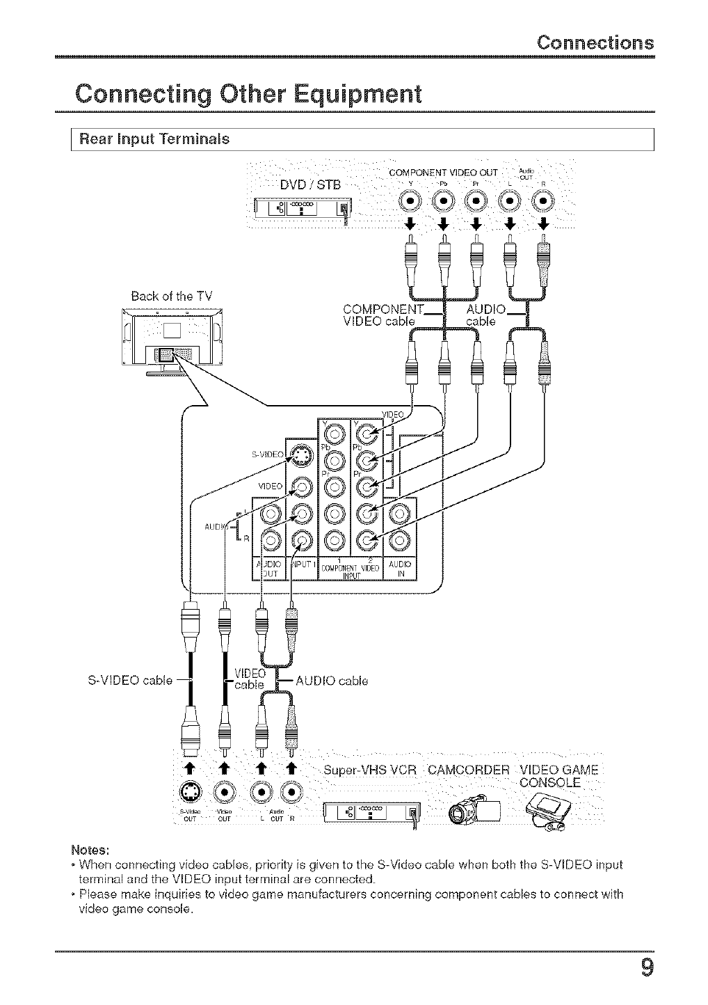
Connecting Other Equipment
I Rear hput Terminals
Back of the TV
S-VIDEO cable -
t_' tt' t1" _1" Super-VHS VCR CAMCORDER V_DEO GAME
Notes:
* When connecting video cables priority is given to the S-Video cable when both the S-VIDEO input
terminal and the VIDEO input terminal are connecled
oPlease make inquiries to video game manufacturers concerning component cables to connect with
video game console.
9
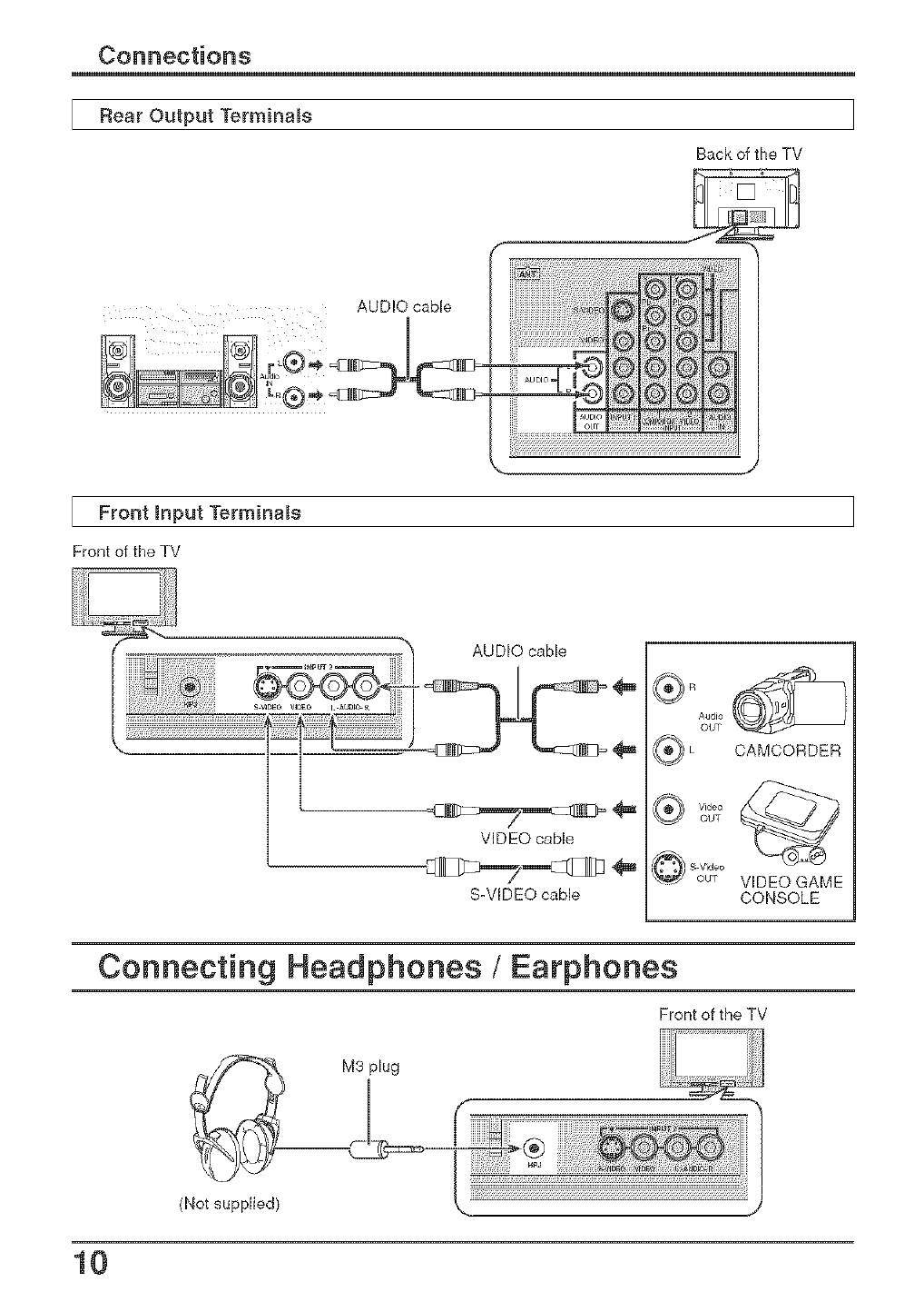
Rear Output Terminals
AUDIO cable
I
Back of the TV
Front input Terminals
Front of the TV
AUDIO cable
VIDEO cable
S-WDEO cable
Audio
OUT
CAMCORDER
_de_
_J out
O SVu_O VIDEO GAME
CONSOLE
Connecting Headphones /Earphones
Front of the TV
(Not supplied)
10
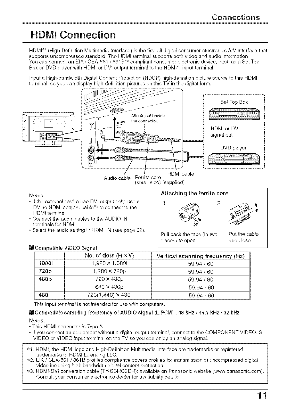
HDMI Connection
HDMI _ (High Definition Multimedia Interface) is the first all digital consumer electronics AiV interface that
supports uncompressed standard The HDMI terminal supports both video and audio information
You can connect an EIA /0EA-861 /861B 2compliant consumer electronic device, such as a Set Top
Box or DVD player with HDMI or DVl output terminal to the HDMI `_input terminal,
Input a High-bandwidth Digital Content Protection (HDCP) high-definition picture source to this HDMI
terminal, so you can display high-definition pictures on this TV in the digital form,
Set Top Box
HDMI or DVI
signal out
DVD player
HDMI cable
Audio cable Ferrite core
(small size) (supplied)
Notes:
, If file external device has DVl output only, use a
DVl to HDMI adapter cable 3to connect to the
HDMI terminal
, Connect the audio cables to the AUDIO IN
terminals for HDMI.
, Select the audio setting in HDMI IN (see page 32)
Attaching the ferdte core
1 2
Pull back the tabs (in two Put the cable
places) to open. and close.
No. of dots (H x V) Vertical scanning frequency (Hz)
1080i 1,920 x 1,080i 59.94 /60
720p 1,280 x 720p 59.94 /60
480p 720 x 480p 59.94 /60
640 x 480p 59.94 /60
480i 720(1,440) x 480i 5994 /60
This input terminal is not intended for use with corn _uters.
[] Compatible sampling frequency of AUDIO siglal (L.PCM} : 48 kNz /44.1 kNz /32 kNz
Notes:
, This HDMI connector is Type A.
, If you connect an equipment without a digital output terminal, connect to the COMPONENT VIDEO. S
VIDEO or VIDEO input terminal on the TV so you can enjoy an analog signal.
'_1, HDMI, the HDM! logo and High-Definition Multimedia Interface are trademarks or registered
trademarks of HDMI Licensing LLC.
'_2, EIA /CEA-861 /861B profiles compliance covers profiles for transmission of uncompressed digital
video including high bandwidth digital content protection.
>:_3.HDMI-DVl conversion cable (TYLSCHO3DH): available on Panasonic website (www.panasonic.com).
Consult your consumer electronics dealer for availability details.
11
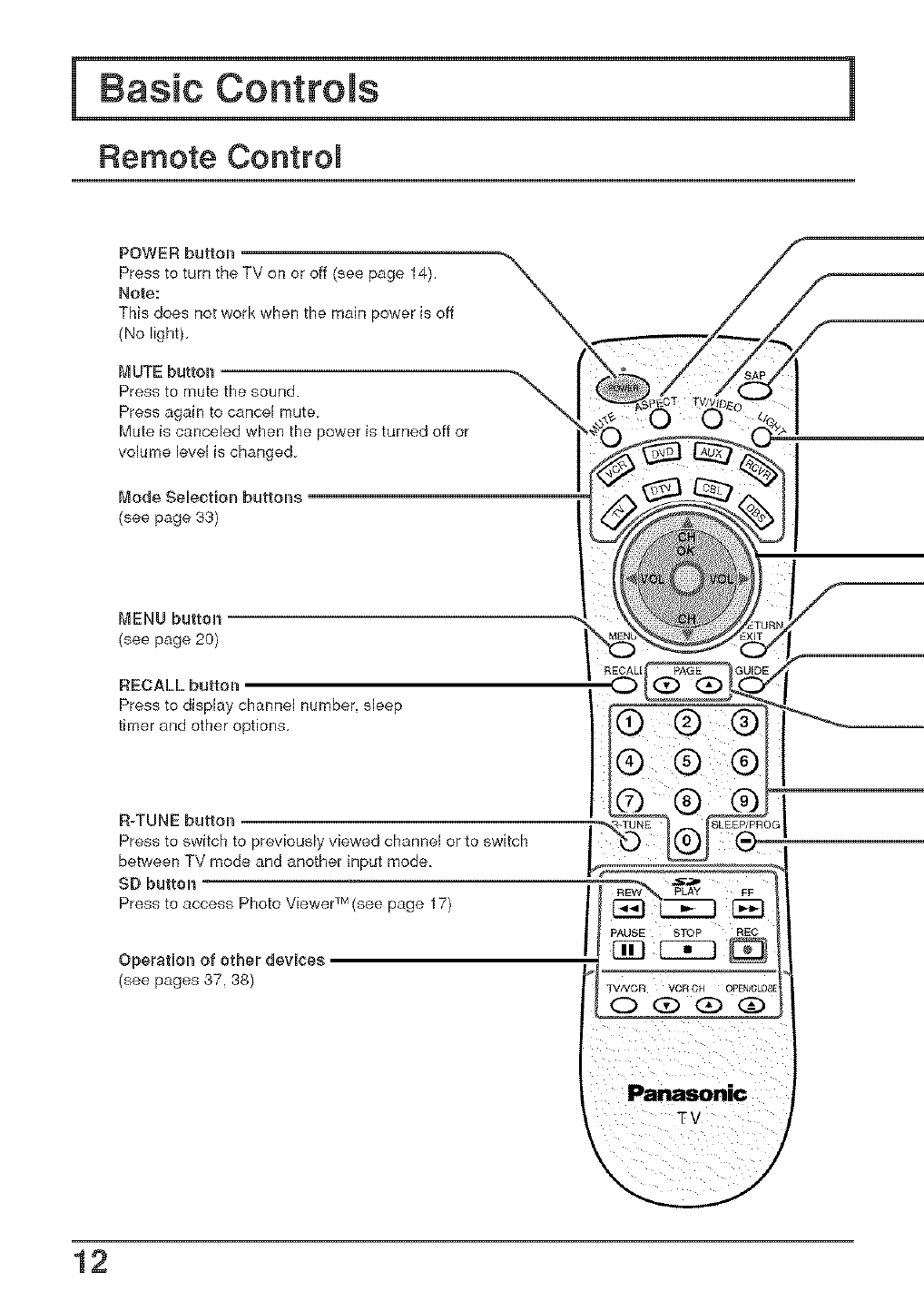
Remote Control
POWER button
Press to turn the TV on or off (see page 14).
Note:
This does not work when the main power is off
(No light),
MUTE button
Press to mute the sound.
Press again to cancel mute
Mute is canceled when the power
volume level is changed
is turned off or
Mode Selection buttons
(see page 33)
MENU button
(see page 20)
RECALL button
Press to display channel number, sleep
timer and other options,
R-TUNE button
Press to switch to previously viewed channel or to switch
between TV mode and another input mode.
SD button
Press to access Photo Viewer TM (see page 17}
Operation of other devices
(see pages 37, 38)
\/
12
Basic Controls
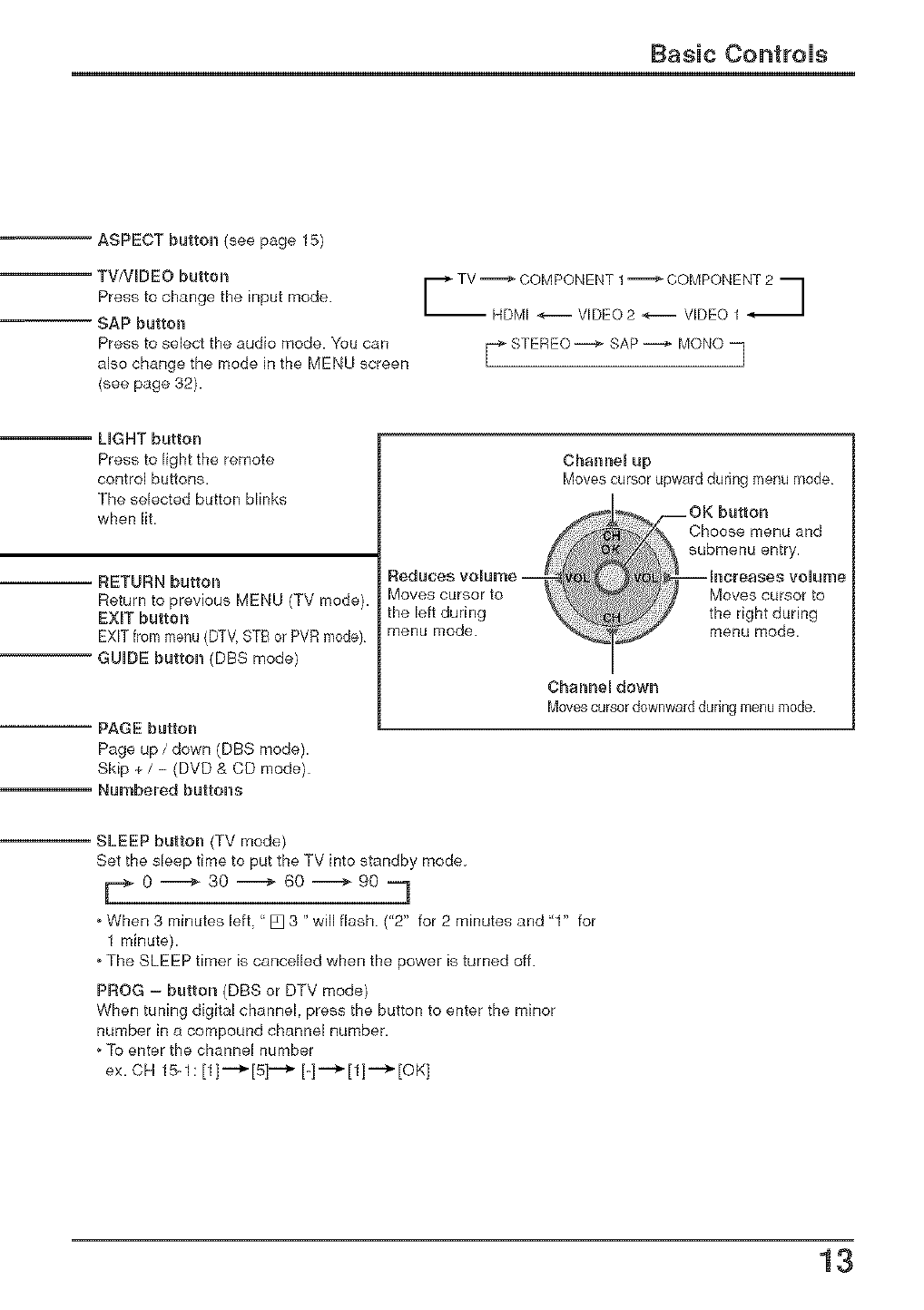
ASPECT button (see page 15)
-- TV/VIDEO button
Press to change the input mode.
SAP button
Press to select the audio mode. You can
also change the mode in the MENU screen
(see page 32).
I -]
_ STEREO--_ SAP --_ MONO
LIGHT button
Press to light the remote
control buttons.
The selected button blinks
when lit,
RETURN button
Return to previous MENU (TV mode).
EXiT button
GUIDE button (DBS mode)
PAGE button
Page up /down (DBS mode).
Skip + /-(DVD & CD mode)
Numbered buttons
Reduces volu[f_e --
Moves cursor to
the left during
menu mode.
Channel up
Moves cursor upward during menu mode
Choose menu and
submenu entry.
Moves cursor to
the right during
menu mode,
Channel dowrl
Movescursordownwardduring menumode.
-- SLEEP button (TV mode)
Set the sleep time to put the TV into standby mode
F 0 =----=_ 30 _ 60 =-------_90 -7
oWhen 3 minutes left, <'[] 3 "will flash ("2" for 2 minutes and "1" for
1 minute)
oThe SLEEP timer is cancelled when the power is turned off.
PROG = button (DBS or DTV mode)
When tuning digital channel, press the button to enter the minor
number in a compound channel number.
oTo enter the channel number
ex. CH 15-1: [1]i'_[5] i'_ [-]i_[1]i_[OK]
13
Basic Controls /Power ON /OFF
Main Unit
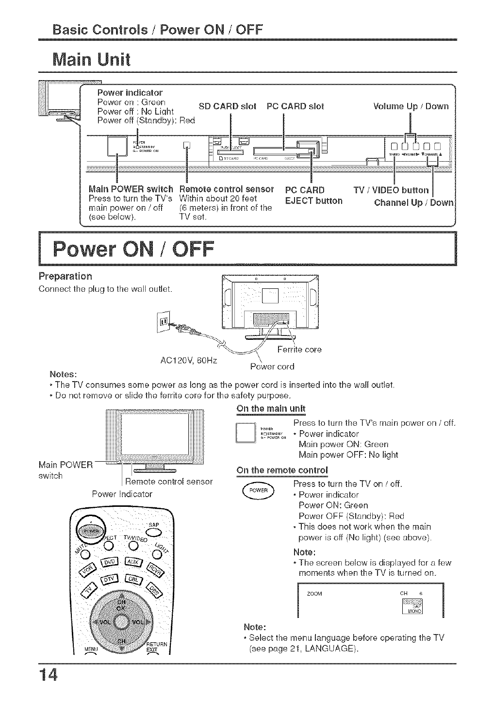
Power Undicator
Power on : Green
Power off : No Liqht
Power off (Standby): Red
SD CARD slot PC CARD slot Volume Up /Down
Main POWER swUtch Remote control sensor
Press to turn the TV's Within about 20 feet
main power on /off /6 meters) in front of the
(see below) TV set
EJECT button Cham_el Up /Down
Preparation outs ° [] _ [_
Connect the plug to the wall . o_] o
Notes:
oThe TV consumes some power as long as the power cord is inserted into the wall outlet,
oDo not remove or slide the ferrite core for the safety purpose.
On the main unit
Main POWER
switch
Press to turn the TV's main power on /off,
o Power indicator
Main power ON: Green
Main power OFF: No light
On the remote control
Remote control sensor
Power Indicator
Press to turn the TV on /off.
,Power indicator
Power ON: Green
Power OFF (Standby): Red
• This does not work when the main
power is off (No light) (see above)
Note:
o The screen below is displayed for a few
moments when the TV is turned on
ZOOM
Note:
,Select the menu language before operating the TV
(see page 21, LANGUAGE),
14
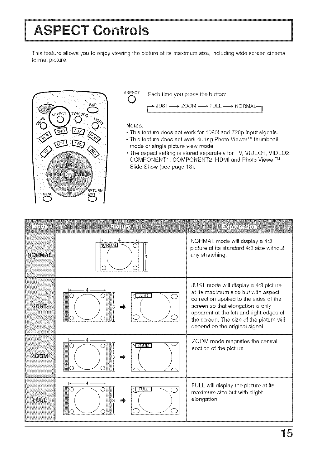
This feature allows you to enjoy viewing the picture at its maximum size. including wide screen cinema
format picture.
ASPECT Each time you press the button:
0
Notes:
o This feature does not work for 1080i and 720p input signals,
o This feature does not work during Photo Viewer TMthumbnail
mode or single picture view mode.
o The aspect setting is stored separately for TV. VIDE01. VIDE02,
COMPONENT1, COMPONENT2. HDMI and Photo Viewer _M
Slide Show (see page 18),
I_ 4 _1
0 0
I-- 4 --I
}-- 4 _1
O(--',_jO I '4'
0 _J 0
X-J
NORMAL mode will display a 4:3
>icture at its standard 4:3 size without
any stretching,
JUST mode will display a 4:3 picture
at its maximum size but with aspect
correction applied to the sides of the
screen so that elongation is only
apparent at the left and right edges of
the screen The size of the picture will
depend on the original signal.
ZOOM mode magnifies the central
section of the picture.
FULL will display the picture at its
maximum size but with slight
elongation.
15
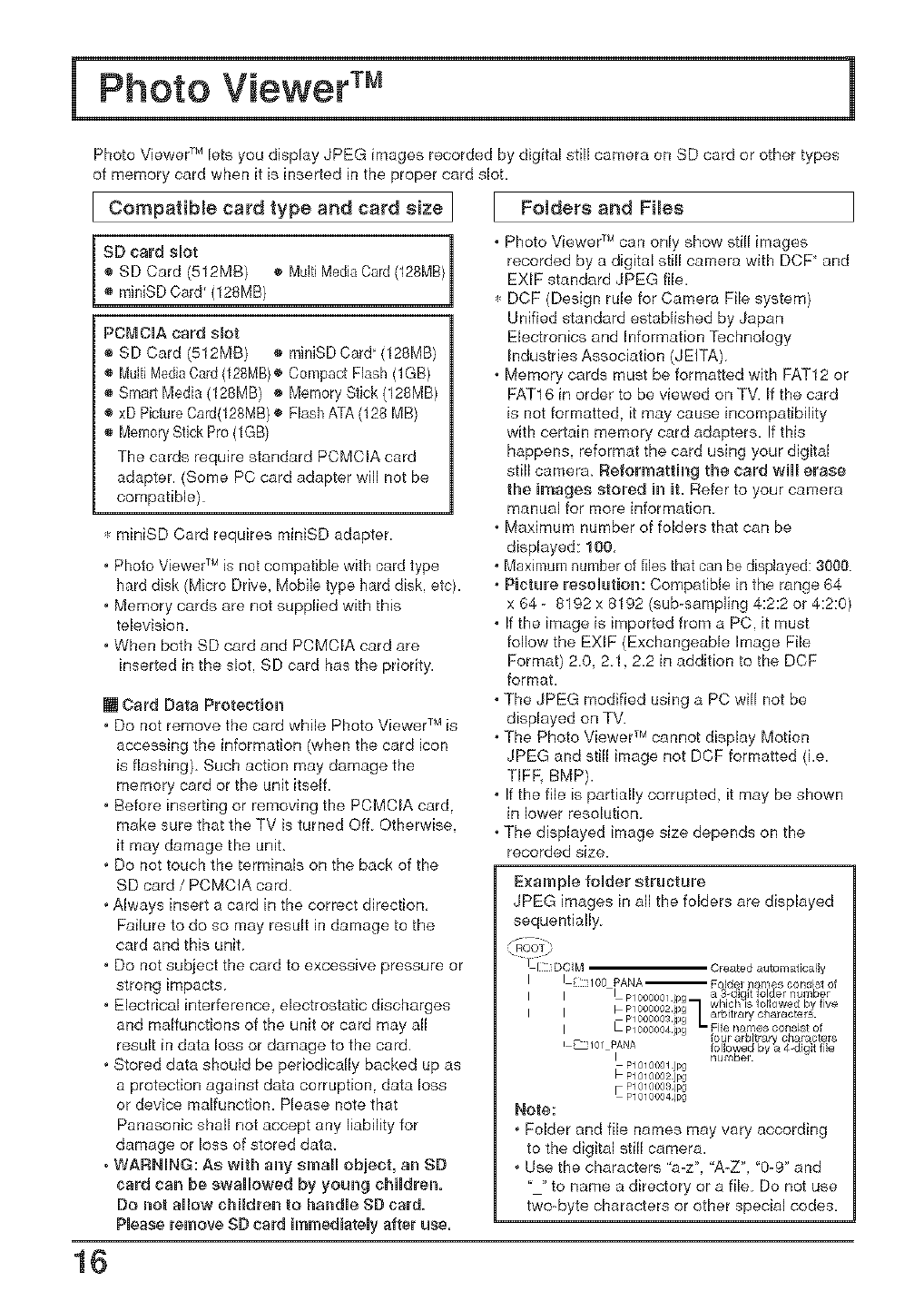
Photo Viewer_Mlets you display JPEG images recorded by digital still camera on SD card or other types
of memory card when it is inserted in the proper card slot.
I Compatible card type and card size I Folders and Fi_es
1
SD card slot |
® SD Card {512MB) ® MultiMediaCard(128MB
1
PCMCIA card slot
® SD Card (512MB) ® miniSD Card (128MB)
® MultiMediaCard(128MB}o Compact Flash (1GB)
® Smart Media (128MB) o Memory Stick {128MB)
® xD PictureCard(128MB)® Flash ATA (128 MB)
The cards require standard PCMCIA card
adapter. (Some PC card adapter will not be
compatible)
miniSD Card requires miniSD adapter.
,Photo Viewer TMis not compatible with card type
hard disk (Micro Drive, Mobile type hard disk, etc).
,Memory cards are not supplied with this
television.
,When both SD card and PCMCIA card are
inserted in the slot, SD card has the priority.
[] Card Data Protection
,Do not remove the card while Photo Viewer T_4is
accessing the information (when the card icon
is flashing) Such action may damage the
memory card or the unit itself
,Before inserting or removing the PCMCIA card.
make sure that the TV is turned Off Otherwise,
it may damage the unit.
,Do not touch the terminals on the back of the
SD card /PCMCIA card
,Always insert a card in the correct direction,
Failure to do so may result in damage to the
card and this unit
,Do not subject the card to excessive pressure or
strong impacts
,Electrical interference, electrostatic discharges
and malfunctions of the unit or card may all
result in data loss or damage to the card,
,Stored data should be periodically backed up as
a protection against data corruption, data loss
or device malfunction. Please note that
Panasonic shall not accept any liability for
damage or loss of stored data.
, WARNING: As with any srnal obiect, an SD
card can be swallowed by young chtdren.
Do not allow chiMren to handle SD card.
Please remove SD card immediately after use.
,Photo Viewer _Mcan only show still images
recorded by a digital still camera with DCF' and
EXlF standard JPEG file.
DCF (Design rule for Camera File system)
Unified standard established by Japan
Electronics and Information Technology
Industries Association (JEITA)
,Memory cards must be formatted with FAT12 or
FAT16 in order to be viewed on TV. If the card
is not formatted, it may cause incompatibility
with certain memory card adapters. If this
happens, reformat the card using your digital
still camera. Reformatting the card will erase
the images stored in it. Refer to your camera
manual for more information.
,Maximum number of folders that can be
displayed: 100,
,Maximum number of files that can be displayed: 3000
,Picture resolution: Compatible in the range 64
x 64 - 8192 x 8192 (sub-sampling 4:2:2 or 4:2:0)
,If the image is imported from a PC. it must
follow the EX_F (Exchangeable Image File
Format) 2.0, 2.1.2.2 in addition to the DCF
format.
,The JPEG modified using a PC will not be
displayed on TV.
,The Photo Viewer TMcannot display Motion
JPEG and still image not DCF formatted (i.e.
TIFR BMP).
,If the file is partially corrupted it may be shown
in lower resolution
,The displayed image size depends on the
recorded size.
Example folder structure
JPEG images in all the folders are displayed
sequentially
Created automatically
I 100 PANA-- Folde_ name_ conr,ist of
I
I
I
i _101 f_ANA
i
Note:
,Folder and file names may vary according
to the digital still camera.
,Use the characters "a-z", "A-Z", "0-9" and
to name a directory or a file Do not use
two-byte characters or other special codes,
16
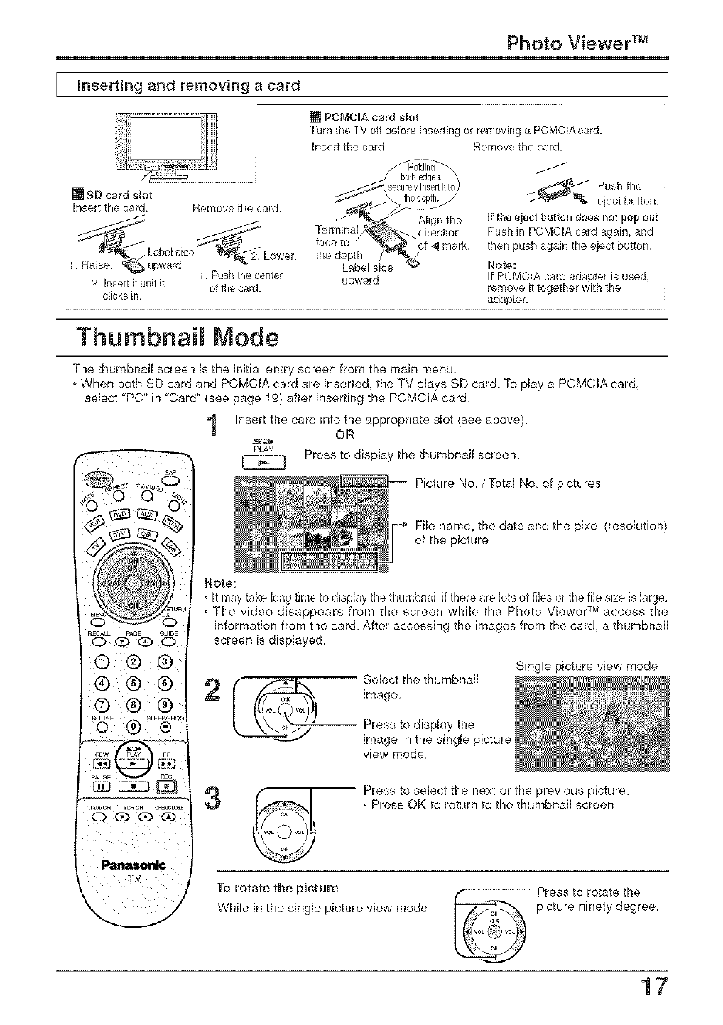
Photo Viewer TM
Inserting and removing a card
[] SD card sJot
hsert the card Remove the card
Lower
[] PCMCIA card slot
Turn the TV off before inserqng or removing a PCMCIAcard.
Insert the card Remove the card
1. Push the center upward
2. Insert it unit it of the card.
clicks in.
Push the
eject button
Jfthe eject buttol_ does not pop out
Push in PCMCIA card again, and
then push again the eject button
Note:
If PCMCIA card adapter is used,
remove it logether with the
adapter.
Thumbnail Mode
The thumbnail screen is the initial entry screen from the main menu.
oWhen both SD card and PCMCIA card are inserted, the TV plays SD card To play a PCMCIA card_
sebct "PC" in "Card" (see page 19) after inserting the PCMCIA card
1Insert the card into the appropriate slot (see above).
OR
pLAy Press to display the thumbnail screen.
Picture No. /Total No of pictures
File name, the date and the pixel (resolution
of the picture
RECA_ pAGE _UI_E
OQG) O
@ ® ®
® ® ®
®® ®
REW FF
_us_ nEe
_'Oa VeReH r)Ra'ICLC_I
Q _ Q _
Note:
,It may take long time to display the thumbnail if there are Iotaof flies or the file size is large,
,The video disappears from the screen while the Photo Viewer TMaccess the
information from the card. After accessing the images from the card, a thumbnail
screen is displayed.
Select the thumbnail
image,
Single picture view mode
Press to display the
image in the single picture
view mode,
3-- Press to select the next or the previous picture.
,Press OK to return to the thumbnail screen.
To rotate the picture
While in the single picture view mode
Press to rotate the
picture ninety degree.
17
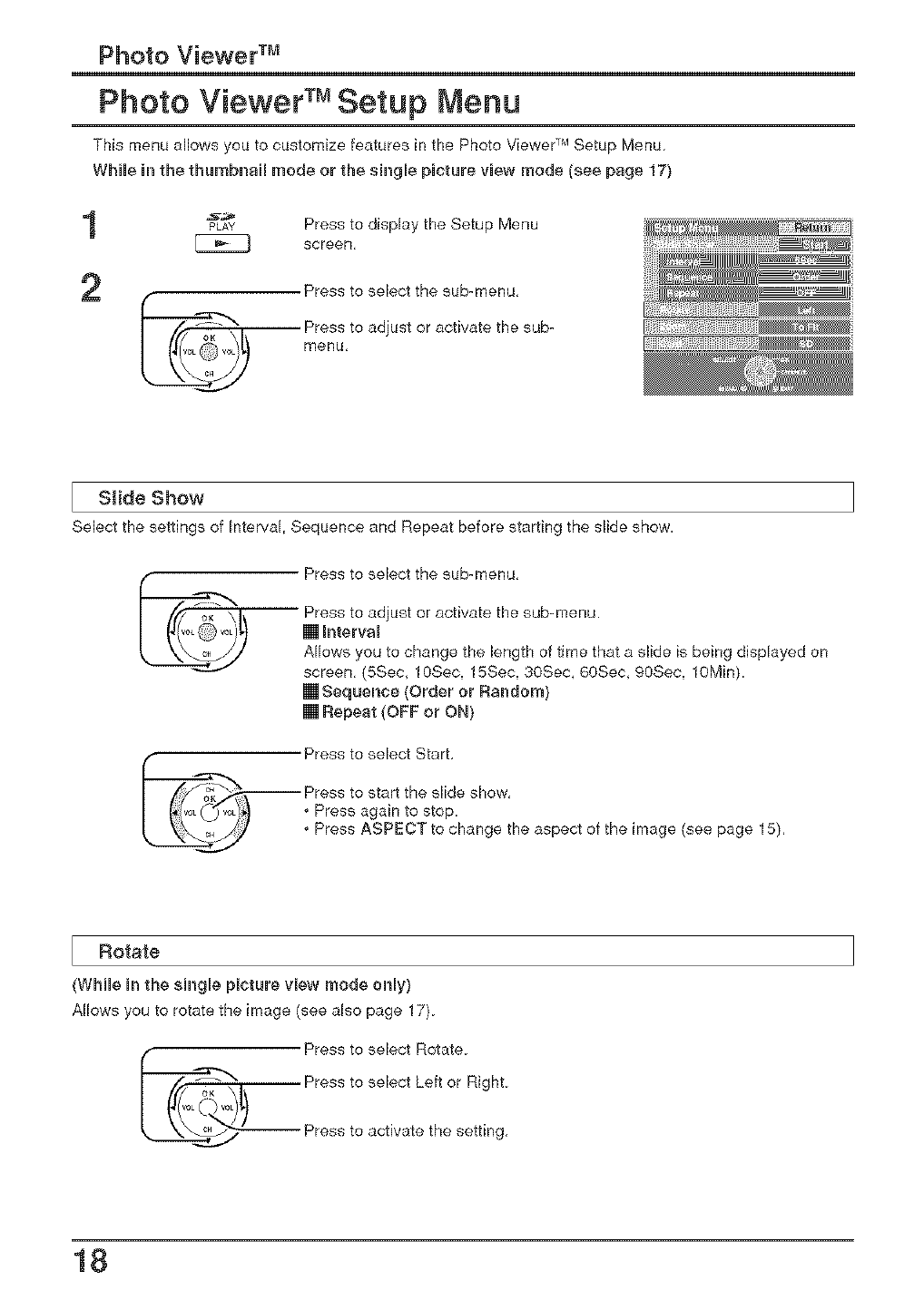
Photo Viewer TM
Photo Viewer TM Setup Menu
This menu allows you to customize features in the Photo Viewer TMSetup Menu
While h_the thumbnail mode or the single pBcture vBew n_ode {see page 17)
1PLAY Press to display the Setup Menu
screen,
2
menu,
Slide Show
Select the settings of Interval, Sequence and Repeat before starting the slide show.
__ Press to select the sub-menu,
Press to adjust or activate the sub-menu.
[] hterval
Allows you to change the length of time that a slide is being displayed on
screen, (5Sec, 10Sec, 15Sec, 30Sec, 60Sec, 90Sec, lOMin).
[] Sequence (Order or Random}
[] Repeat (OFF or ON}
_/_..iiii Press to select Start,
Press to start the slide show,
I(_(_ 0/_,_!_ Press again to stop.
_______j Press ASPECT to change the aspect of the image (see page 15),
Rotate
(While h_the sUngle picture mew mode only)
Allows you to rotate the image (see also page 17).
_ Press to select Rotate.
Press to select Left or Right.
Press to activate the setting,
18
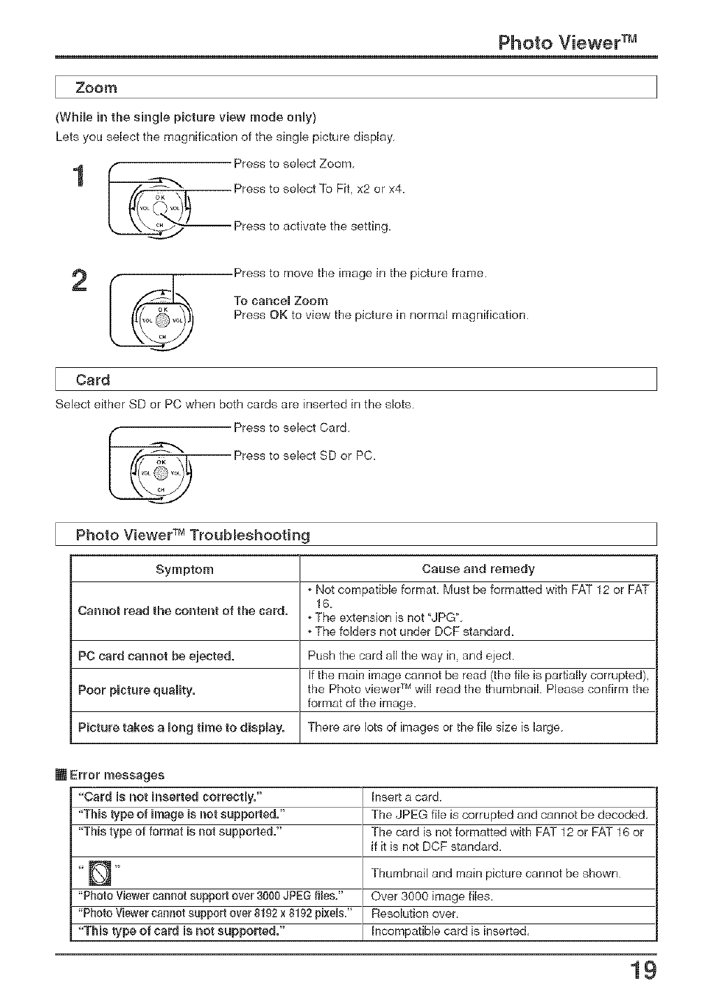
Photo Viewer TM
Zoom
(While in the single picture view mode only}
Lets you select the magnification of the single picture display.
1 Press toselect Zoom,
Press to select To Fit, x2 or x4.
t _'---_ Press to activate the setting.
2Press to move the image in the picture frame.
To cancel Zoom
Press OK to view the picture in normal magnification.
Card
Select either SD or PC when both cards are inserted in the slots.
Press to select Card.
Press to select SD or PC.
Photo Viewer TM Troubleshooting
Symptom Cause and remedy
oNot compatible format. Must be formatted with FAT 12 or FAT
16.
Cam_ot read the content of the card. oThe extension is not "JPGL
oThe folders not under DCF standard.
PC card cannot be ejected. Push the card all the way in, and eject.
If the main image cannot be read (the file is partially corrupted),
Poor picture quality, the Photo viewer ]M will read the thumbnail. Please confirm the
format of the image.
Picture takes a long time to display. There are lots of images or the file size is large.
"Card is not inserted correctly=" Insert a card.
"This type of image is net supported=" The JPEG file is corrupted and cannot be decoded,
"This type of format is not supported." The card is not formatted with FAT 12 or FAT 16 or
if it is not DCF standard.
" _" Thumbnail and main picture cannot be shown.
"Photo Viewer cannot support over 3000JPEG flies." Over 3000 image files.
"Photo Viewer ca_motsupport over 8192x 8192 pixeIs." Resolution over,
"This _,pe of card ie not sappmled." Incompatible card is inserted,
19
I
20
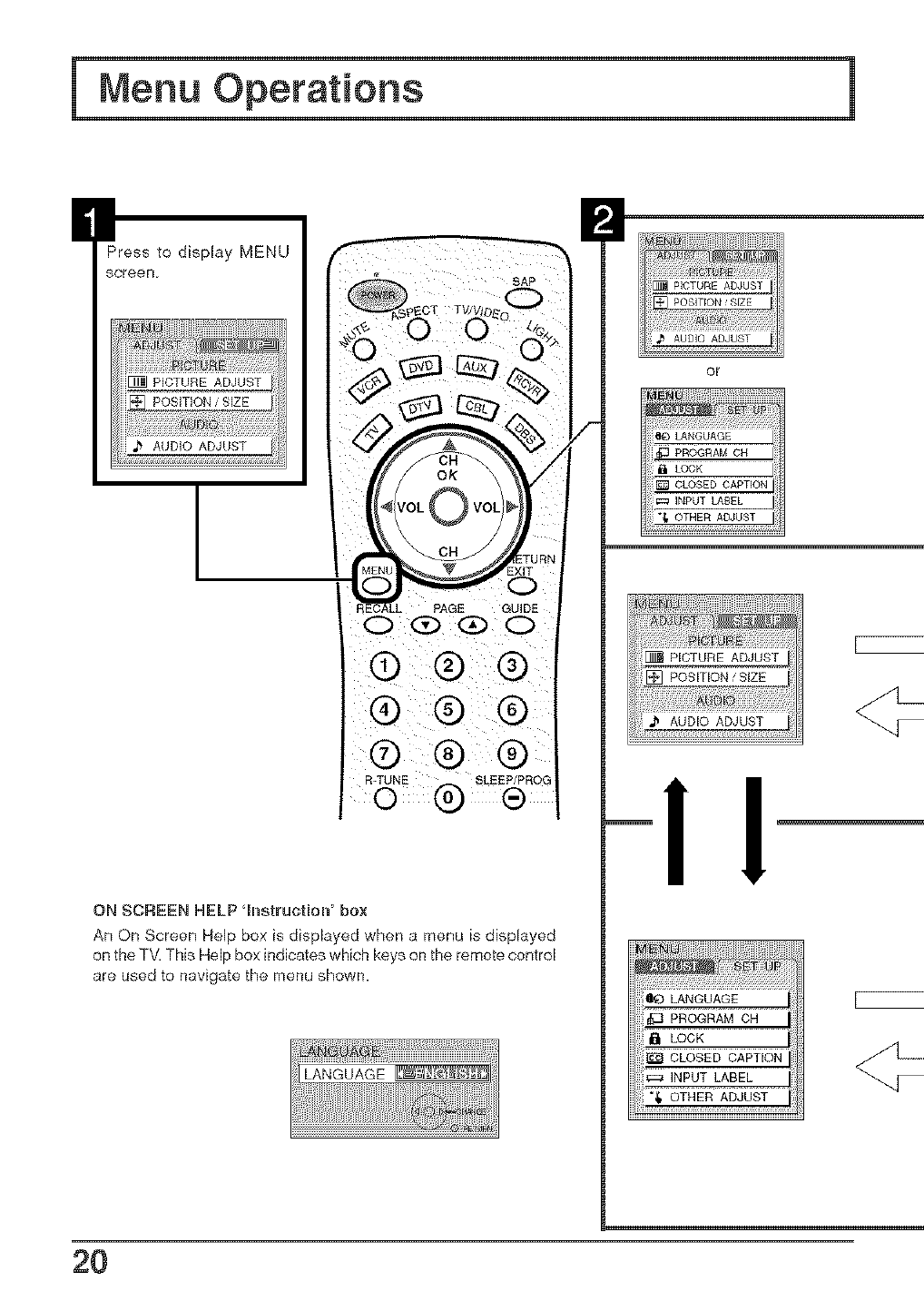
IPress to display MENU
screen
AUDIO ADJUST
I
SAP
PAGE GUIDE
ON SCREEN HELP qDStrUctJOW box
An On Screen Help box is displayed when a menu is displayed
on the TV. This Help box indicates which keys on the remote control
are used to navigate the menu shown.
LANGUAGE
I
or
LOCK
CLOSED CAPTION
INPUT LABEL
OTHER ADJUST
LOCK
_=:_INPUT LABEL
OTHER ADJUST
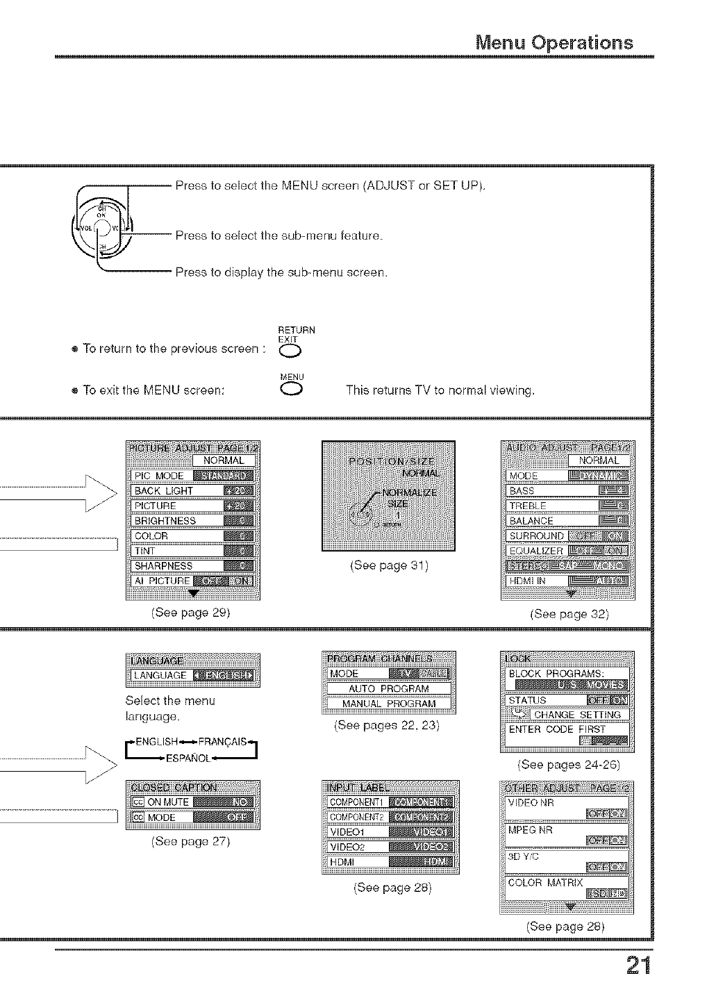
Menu Operations
_ Press to select the MENU screen (ADJUST or SET UP),
RETURN
EXIT
® To return to the previous screen :
MENU
® To exit the MENU screen: O This returns TV to normal viewing,
iP_P/C MODE
BACK LIGHT
PICTURE
BRIGHTNESS
COLOR
TINT
SHARPNESS
AI PICTURE
iiii
(See page 29)
(See page 31)
MODE
BASS
TREBLE
BALANCE
EQUALIZER_
HDMI IN
(See page 32)
Selectthe menu
language. (See pages 22, 23)
(See page 28}
BLOCK PROGRAMS:
STATUS
ENTER CODE FIRST
(See pages 24-26)
VIDEO NR
MPEG NR
3D Y_
COLOR MATRIX
(See page 28)
21
Menu Operations
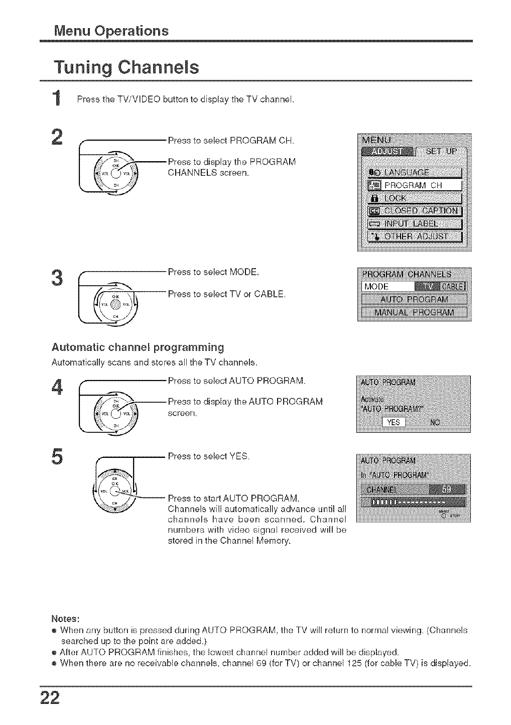
Tuning ChanneJs
1 Press the TV/VIDEO button to display the TV channel.
2
_/...,____ Press to select PROGRAM CH.
Press to display the PROGRAM
I ORANNELSscreon
__.LJ
Automatic channel programming
Automatically scans and stores all the TV channels.
_/_iPress to select AUTO PROGRAM
Press to display the AUTO
i screen PROGRAM
5Press to select YES,
_ Press to start AUTO PROGRAM
"_-.._ Channels will automatically advance until all
channels have been scanned Channel
numbers with video signal received will be
stored in the Channel Memory.
Notes:
® When any button is pressed during AUTO PROGRAM, the TV will return to normal viewing (Channels
searched up to the point are added)
® After AUTO PROGRAM finishes, the lowest channel number added will be displayed
® When there are no receivable channels, channel 69 {for TV) or channel 125 (for cable TV) is displayed.
22
Menu Operations
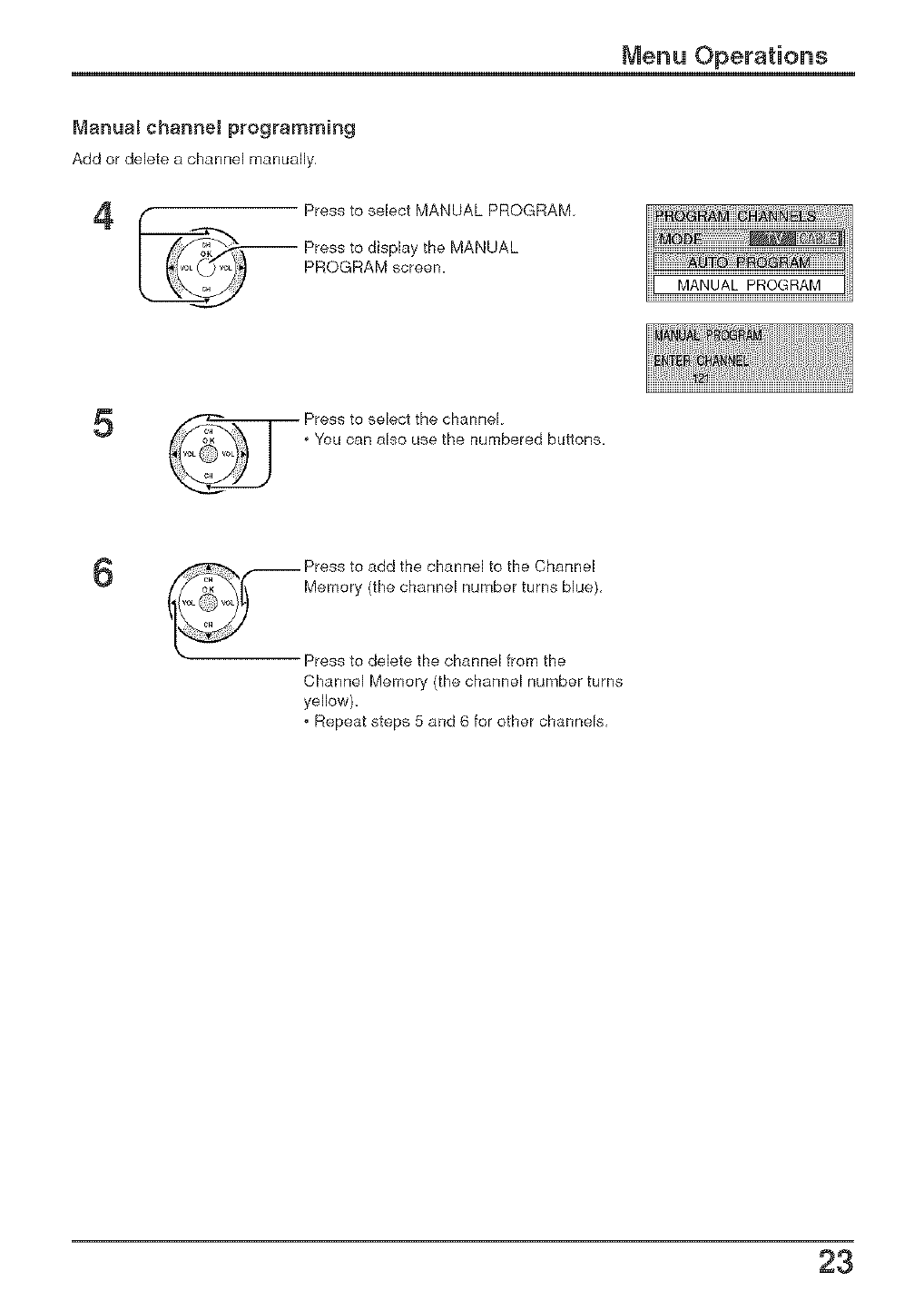
Manua_ channel programming
Add or delete a channel manually,
PROGRAM screen.
5Press to select the channel
You can also use the numbered buttons.
6-- Press to add the channel to the Channel
Memory (the channel number turns blue),
Press to delete the channel from the
Channel Memory (the channel number turns
yellow).
. Repeat steps 5 and 6 for other channels,
23
Menu Operations
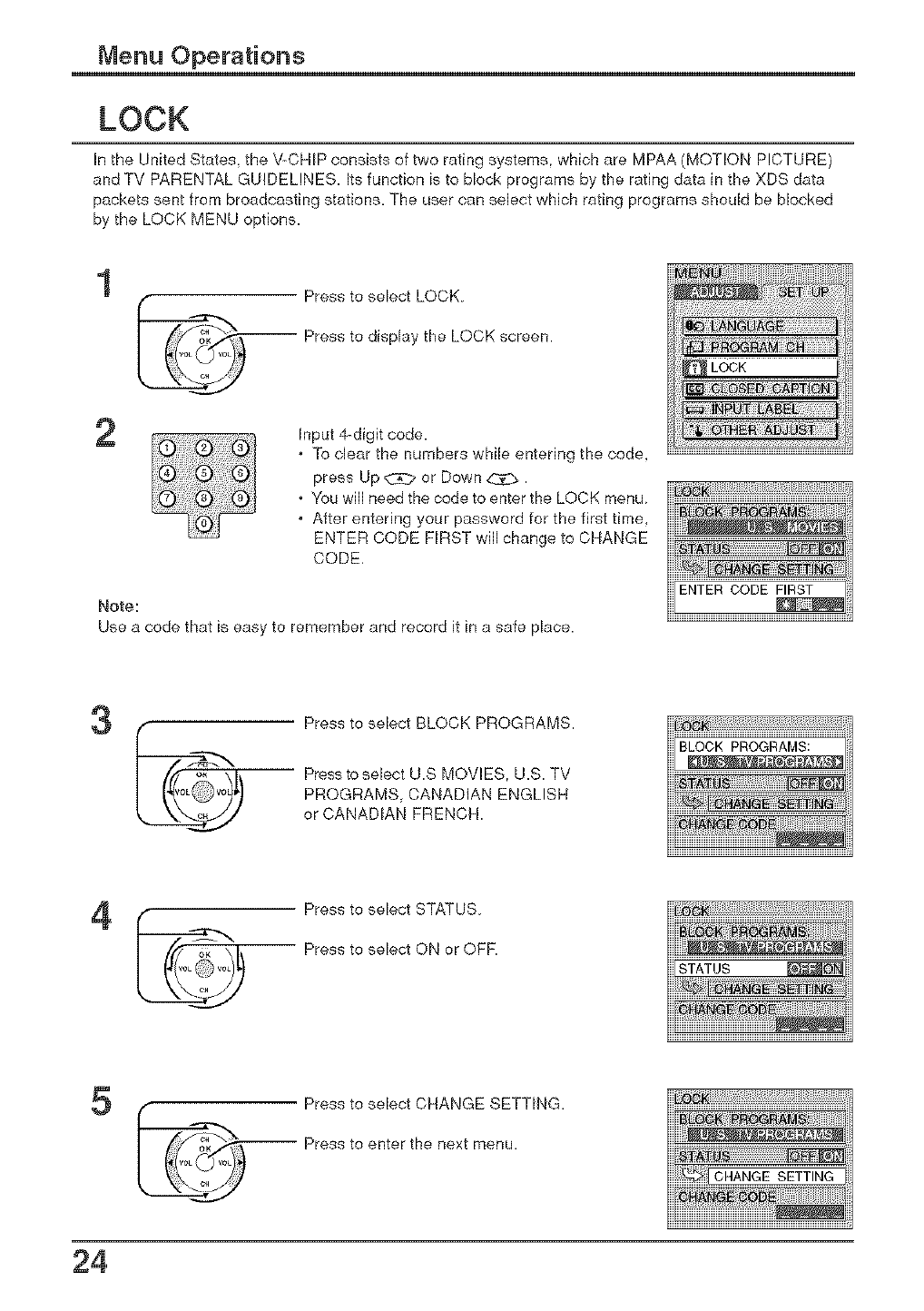
LOCK
In the United States, the V-CHIP consists of two rating systems, which are MPAA (MOTION PICTURE)
and TV PARENTAL GUIDELINES. Its function is to block programs by the rating data in the XDS data
packets sent from broadcasting stations. The user can select which rating programs should be blocked
by the LOCK MENU options.
1
2
Press to select LOCK
-- Press to display the LOCK screen.
Input 4-digit code.
To clear the numbers while entering the code,
press Up _ or Down _.
You will need the code to enter the LOCK menu
After entering your password for the first time,
ENTER CODE FIRST will change to CHANGE
CODE,
Note:
Use a code that is easy to remember and record it in a safe place.
3Press to select BLOCK PROGRAMS.
Press to select U.S MOVIES. U.S. TV
PROGRAMS, CANADIAN ENGLISH
or CANADIAN FRENCH
Press to select STATUS
-- Press to select ON or OFF
5Press to select CHANGE SETTING.
-- Press to enter the next menu.
24
Menu Operations
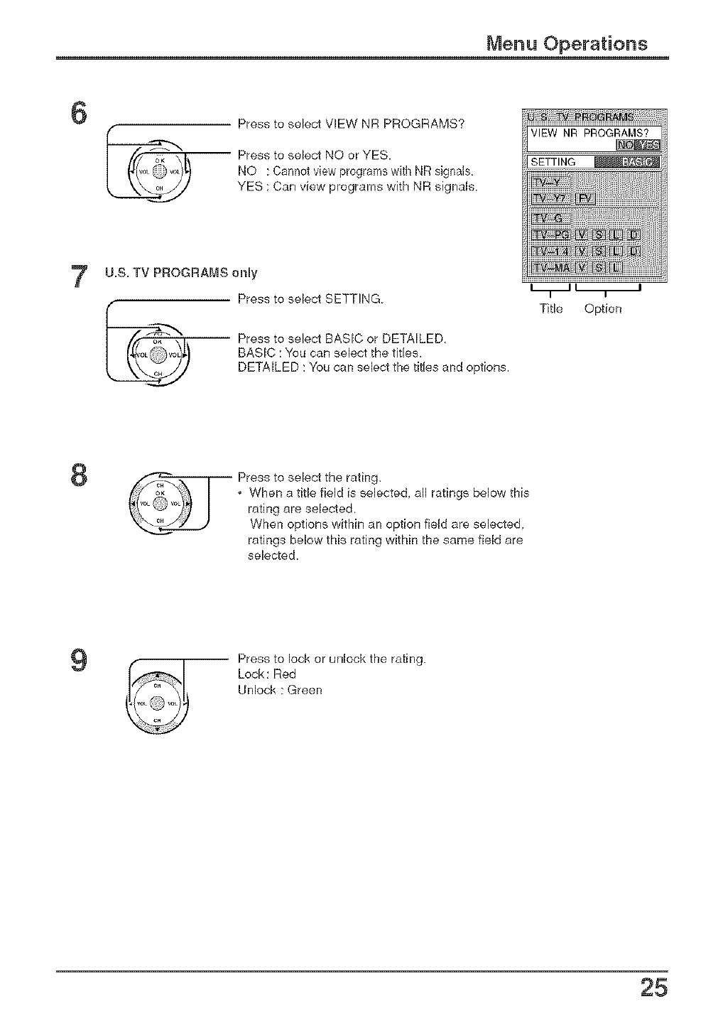
6Press to select VIEW NR PROGRAMS?
Press to select NO or YES.
NO : Cannot view programs with NR signals
YES : Can view programs with NR signals
7U.S. TV PROGRAI_S only
Press to select SETTING
Press to select BASIC or DETAILED,
BASIC : You can select the titles.
DETAILED : You can select the titles and options.
Title Option
8Press to select the rating,
,When a title field is selected, all ratings below this
rating are selected.
When options within an option field are selected.
ratings below this rating within the same field are
selected.
9-- Press to lock or unlock the rating
Lock : Red
Unlock : Green
25
Menu Operations
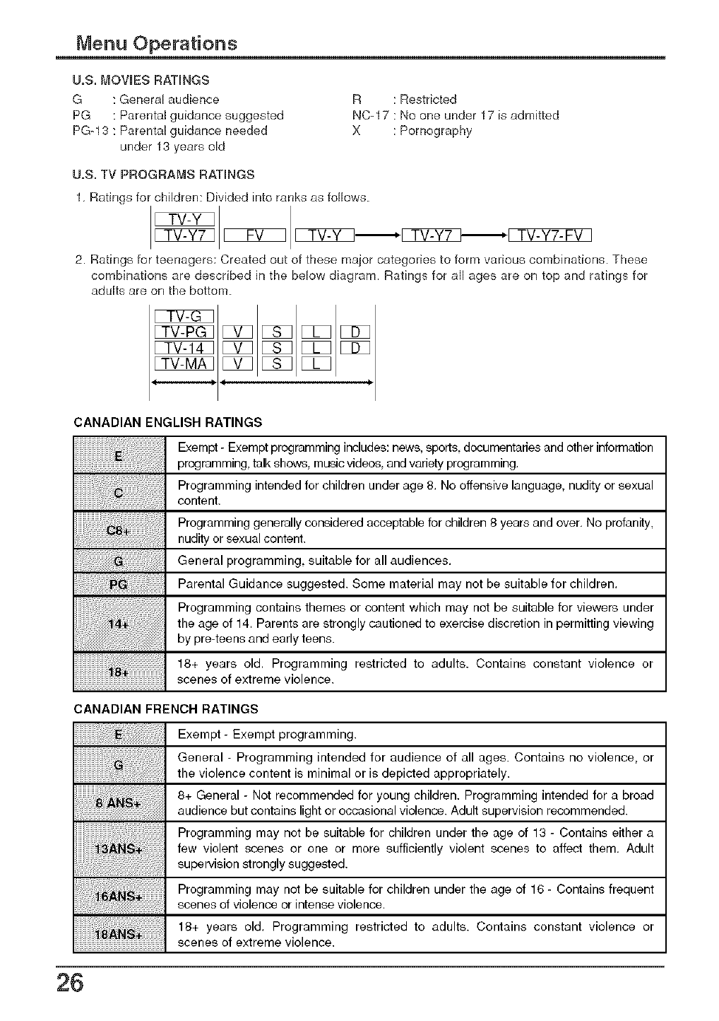
U=S=MOVIES RATINGS
G : General audience
PG : Parental guidance suggested
PG-13 : Parental guidance needed
under 13 years old
R : Restricted
NC-17 : No one under 17 is admitted
X : Pornography
U=S=TV PROGRAMS RATINGS
1, Ratings for children: Divided into ranks as follows
2. Ratings for teenagers: Created out of these tuner categories to form various combinations. These
combinations are described in the below diagram. Ratings for all ages are on top and ratings for
adults are on the bottom.
CANADIAN ENGLISH RATINGS
Exempt - Exempt programming includes: news, sports, documentaries and other information
programming, talk shows, music videos, and variety programming.
Programming intended for children under age 8. No offensive language, nudity or sexual
content.
Programming generally considered acceptable for children 8 years and over. No profanity,
nudity or sexual content.
General programming, suitable for all audiences.
Parental Guidance suggested. Some material may not be suitable for children.
Programming contains themes or content which may not be suitable for viewers under
the age of 14. Parents are strongly cautioned to exercise discretion in permitting viewing
by pre-teens and early teens.
18+ years old. Programming restricted to adults. Contains constant violence or
scenes of extreme violence.
CANADIAN FRENCH RATINGS
Exempt - Exempt programming.
General - Programming intended for audience of all ages. Contains no violence, or
the violence content is minimal or is depicted appropriately.
8+ General - Not recommended for young children. Programming intended for a broad
audience but contains light or occasional violence. Adult supervision recommended.
Programming may not be suitable for children under the age of 13 - Contains either a
few violent scenes or one or more sufficiently violent scenes to affect them. Adult
supervision strongly suggested.
Programming may not be suitable for children under the age of 16 - Contains frequent
scenes of violence or intense violence.
18+ years old. Programming restricted to adults. Contains constant violence or
scenes of extreme violence.
26
Menu Operations
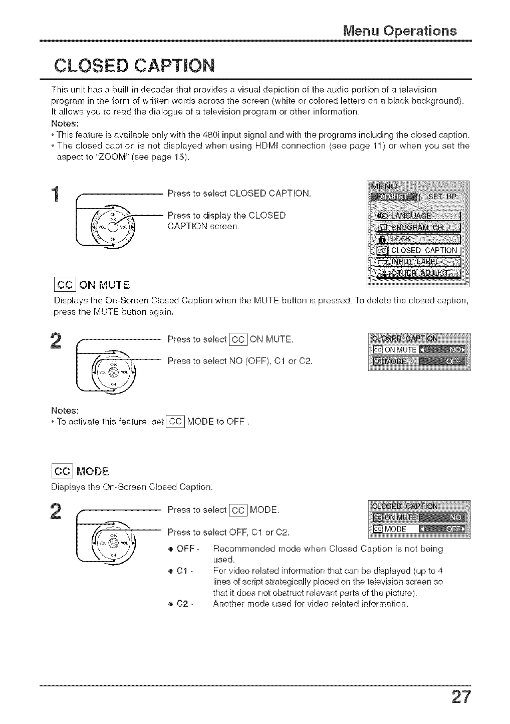
CLOSED CAPTION
This unit has a built in decoder that provides a visual depiction of the audio portion of a television
program in the form of written words across the screen (white or colored letters on a black background).
It allows you to read the dialogue of a television program or other information.
Notes:
oThis feature is available only with the 480i input signal and with the programs including the closed caption
oThe closed caption is not displayed when using HDMI connection (see page 11) or when you set the
aspect to "ZOOM" (see page 15).
1Press to select CLOSED CAPTION,
iPress to display the CLOSED
CAPTION screen.
[_ ON MUTE
Displays the On-Screen Closed Caption when the MUTE button is pressed To delete the closed caption,
press the MUTE button again,
Press to select _ ON MUTE.
-- Press to select NO (OFF) C1 or 02,
Notes:
oTo activate this feature, set _ MODE to OFF
L_
[_ MODE
Displays the On-Screen Closed Caption
2Press to select _ MODE.
iPress to select OFF, 01 or C2,
® OFF - Recommended mode when Closed Caption is not being
used
® 01 - For video related information that can be displayed {up to 4
lines of script strategically placed on the television screen so
that it does not obstruct relevant parts of the picture).
® 02 - Another mode used for video related information.
27
Menu Operations
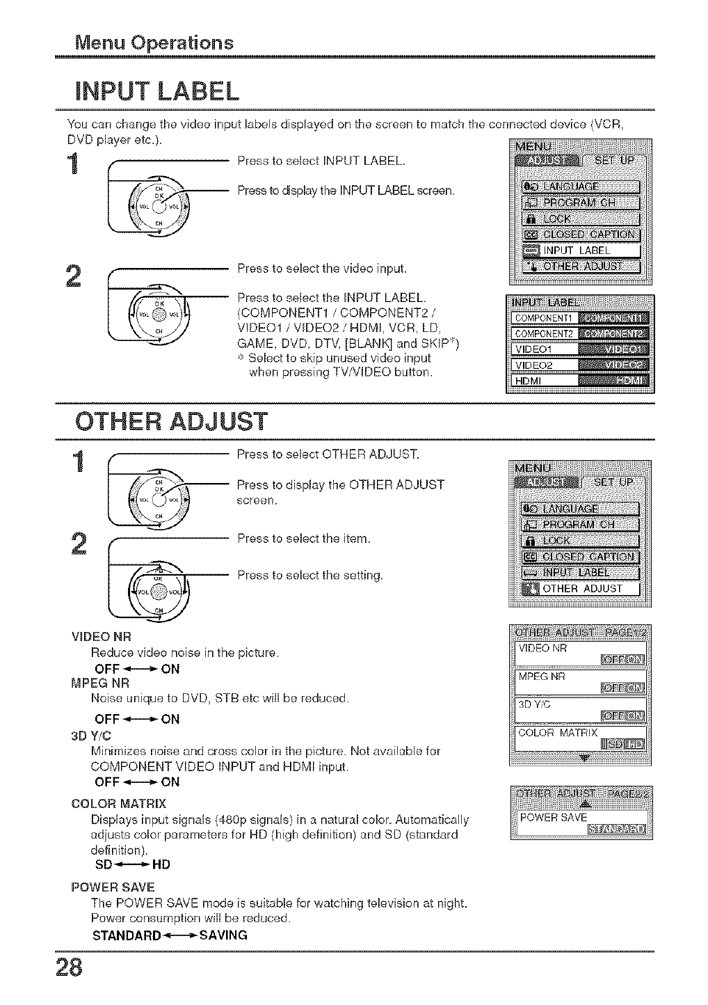
NPUT LABEL
You can change the video input labels displayed on the screen to match the connected device (VCR,
DVD player etc.)
1Press to select INPUT LABEL,
Press to display the INPUT LABEL screen
2Press to select the video input,
Press to select the INPUT LABEL
(COMPONENT1 /COMPONENT2 /
VIDEO1 /VIDEO2 /HDMI, VCR, LD,
GAME, DVD, DTV. [BLANK] and SKIP)
_'_Select to skip unused video input
when pressing TV/VIDEO button.
OTHER ADJUST
Press to select OTHER ADJUST.
-- Press to display the OTHER ADJUST
screen.
Press to select the item.
iPress to select the setting,
o_
VIDEO NR
Reduce video noise in the picture.
OFF _.ii_ ON
MPEG NR
Noise unique to DVD, STB etc will be reduced.
OFF _-..._- ON
3D Y/C
Minimizes noise and cross color in the picture. Not available for
COMPONENT VIDEO INPUT and HDMI input.
OFF _-_ ON
COLOR MATRIX
Displays input signals (480p signals) in a natural color Automatically
adjusts color parameters for HD [high definition) and SD (standard
definition).
SD _-i..._ HD
POWER SAVE
The POWER SAVE mode is suitable for watching television at night.
Power consumption will be reduced.
STANDARD_,--_SAVING
VIDEO NR
MPEGNR
3D Y_
COLOR MATRIX
28
Menu Operations
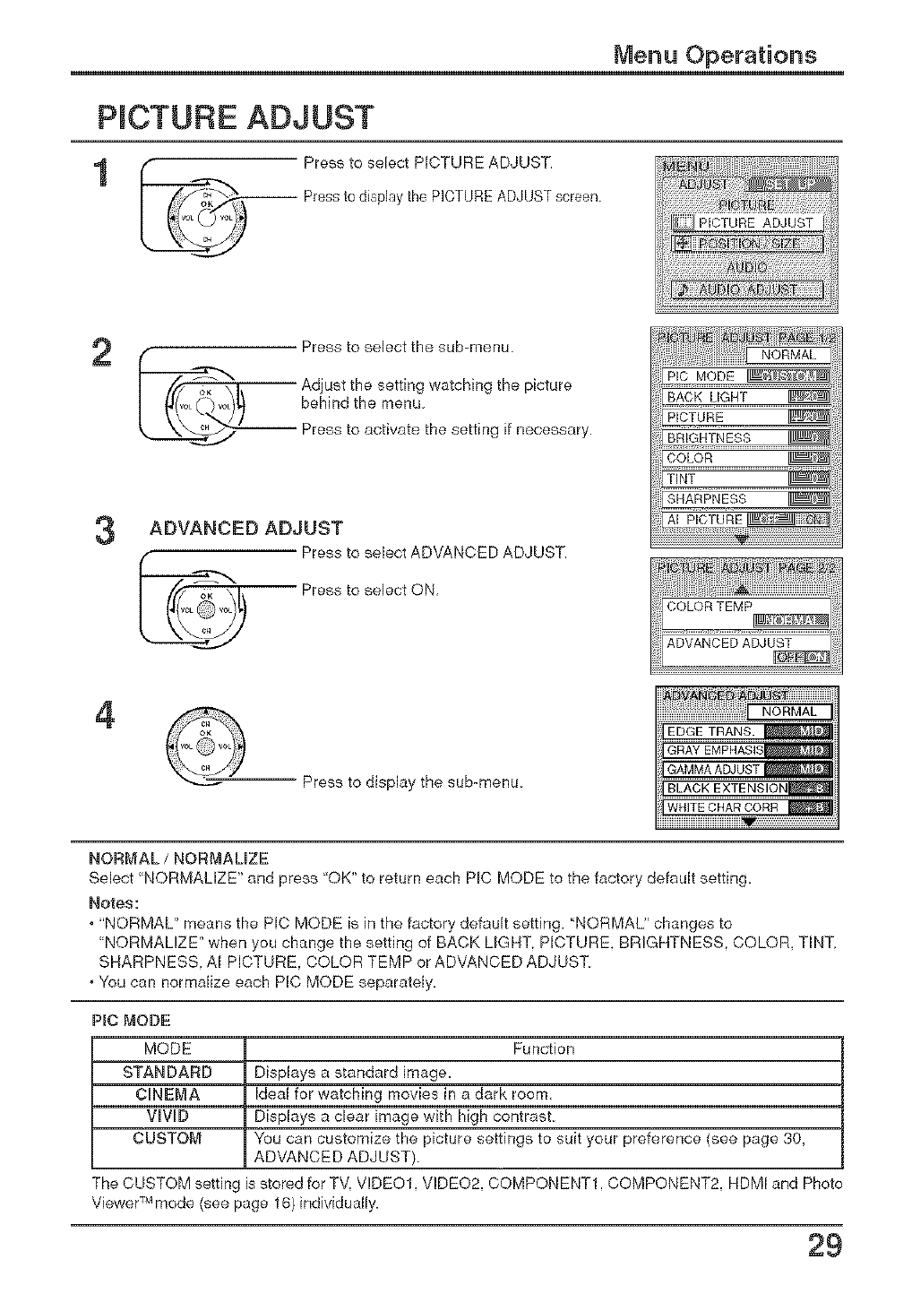
PICTURE ADJUST
Press to select PICTURE ADJUST.
Press to disphy the PICTUREADJUST screen
Press to select the sub-menu
f
_f'_ Adjust the setting watching the picture
I _/_o_,,_)_ behind the menu
_ Press to activate the setting if necessary.
3ADVANCED ADJUST
Press to select ADVANCEDADJUST.
'-----"_-- Press to select ON,
4
Press to display the sub-menu
EDGE TRANS. l_l[_l
GRAY EMPHASIS_&IJ_I
BLACK EXTENSION_I
WRITE CHAR CORR _=_1
NORMAL /NORMALIZE
Select "NORMALIZE" and press "OK" to return each PIC MODE to the factory default setting.
Notes:
, "NORMAL" means the PIC MODE is in the factory default setting. "NORMAL" changes to
"NORMALIZE" when you change the setting of BACK LIGHT. PICTURE. BRIGHTNESS COLOR. TINT
SHARPNESS AI PICTURE. COLOR TEMP or ADVANCED ADJUST
, You can normalize each PIC MODE separately.
Pie MODE
MODE Function
STANDARD Displays a standard image.
CINEMA Ideal for watching movies in a dark room,
VIVID Displays a clear image with high contrast
CUSTOM You can customize the picture settings to suit your preference (see page 30,
ADVANCED ADJUST)
The CUSTOM settin< is stored for TV, VIDEO1, VIDEO2, COMPONENT1, COMPONENT2, HDM_ and Photo
TM
Viewer mode (see page 16) individually.
29
Menu Operations
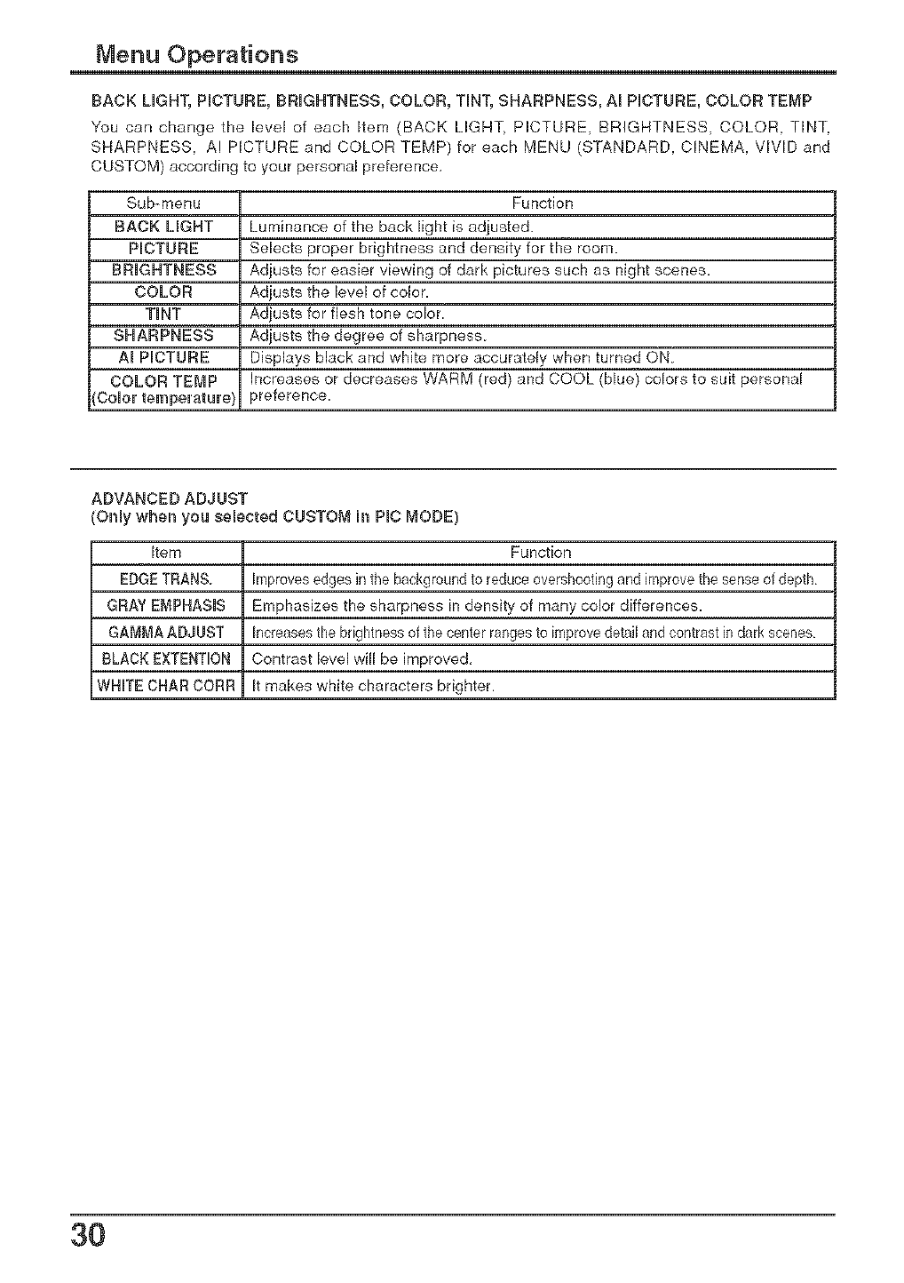
BACK LIGHT, PICTURE, BRIGHTNESS, COLOR, TINT, SHARPNESS, AI PICTURE, COLOR TEMP
You can change the level of each item (BACK LIGHT, PICTURE, BRIGHTNESS, COLOR, TINT,
SHARPNESS, AI PICTURE and COLORTEMP) for each MENU (STANDARD, C_NEMA, VIVIDand
CUSTOM) according to your personal preference,
Sub-menu Function
BACK LIGHT Luminance of the back light is adjusted.
PICTURE Selects proper brightness and density for the room.
BRIGHTNESS Adjusts for easier viewing of dark pictures such as night scenes.
COLOR Adjusts the level of color.
TiNT Adjusts for flesh tone color.
SHARPNESS Adjusts the degree of sharpness
AI PICTURE Displays black and white more accurately when turned ON.
COLOR TEMP Increases or decreases WARM (red) and COOL (blue) colors to suit personal
{Color temperature} preference.
ADVANCED ADJUST
(Only when you selected CUSTOM h_ PIC MODE)
Item Function
EDGETRANS. Improvesedges inthe background to reduce overshooting and improvethe sense of depth
GRAY EMPHASIS Emphasizes the sharpness in density of many color differences.
GAMMA ASJUST Increases the brightness of the center ranges to improve detail and contrast in dark scenes
BLACK EXTENT_OR Contrast level will be improved,
WHITE CHAR COBS It makes white characters brighter.
3O
Menu Operations
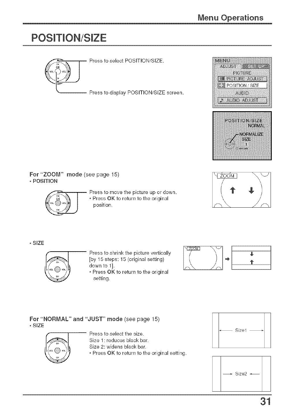
POS T ON/S ZE
Press to select POSITION/SIZE.
Press to display POSITION/SIZE screen.
For "ZOOM" mode (see page 15)
, POSITION
Press to move the picture up or down.
,Press OK to return to the original
position,
, SIZE
[by 15 steps: 15 (original setting)
down to 1].
,Press OK to return to the original
setting,
l-
Size1
Size2
31
For "NORMAL" and "JUST" mode (see page 15)
, SIZE
Press to select the size
Size 1: reduces black bar
Size 2: widens black bar,
, Press OK to return to the original setting.
Menu Operations
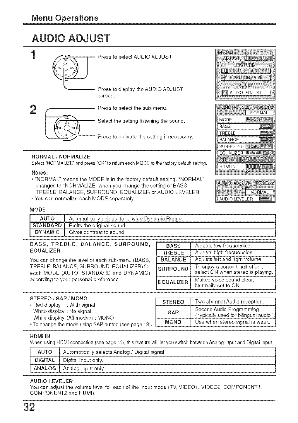
AUDIO ADJUST
1Press to select AUDIO ADJUST,
Press to display the AUDIO ADJUST
screen. AUDIO ADJUST
2Press to select the sub-menu.
iSelect the setting listening the sound.
Press to activate the setting if necessary
NORMAL /NORi'_AMZE
SNect"NORMALIZE"and press "OK"to return eachMODEto thefactory defaultsetting.
Notes:
o 'NORMAL" means the MODE is in the factory default setting, 'NORMAL"
changes to "NORMALIZE" when you change the setting of BASS.
TREBLE. BALANCE, SURROUND, EQUALIZER or AUDIO LEVELER.
oYou can normalize each MODE separately. AUDIO LEVELER
MODE
AUTO
STANDARD
I DYNAMIC
Automatically adiusts for a wide Dynamic Range
Emits the original sound
Gives contrast to sound
BASS, TREBLE, BALANCE, SURROUND,
EQUALIZER
You can change the level of each sub-menu (BASS,
TREBLE, BALANCE. SURROUND. EQUALIZER) for
each MODE (AUTO, STANDARD and DYNAMIC)
according to your personal preference
BASS Adjusts low frequencies.
TREBLE Adjusts high frequencies.
BALANCE Adjusts left and right volume
SURROUND To enjoy a concert hall effect,
select ON when stereo is playing
EQUALIZER Makes voice sound clear.
Normally set to ON.
STEREO /SAP /MONO
o Red display : With signal
White display : No signal
White display (All modes) : MONO
o[b change the mode using SAP button (see page 13),
STEREO Two channel Audio reception.
Second Audio Programming
SAP ( typically used for bilingual audio )
MONO Use when stereo signal is weak
HDMI IN
When using HDMI connection (see page 11),this feature will let you switch between Analog Input and Digital Input.
t UTO Automatically selects Analog /Digital signal.
DIGITAL Digital Input only.
ANALOG Analog Input only
AUDIO LEVELER
You can adjust the volume level for each of the input mode (TV, VIDEO1, VIDEO2, COMPONENT1,
COMPONENT2 and HDMI)
32
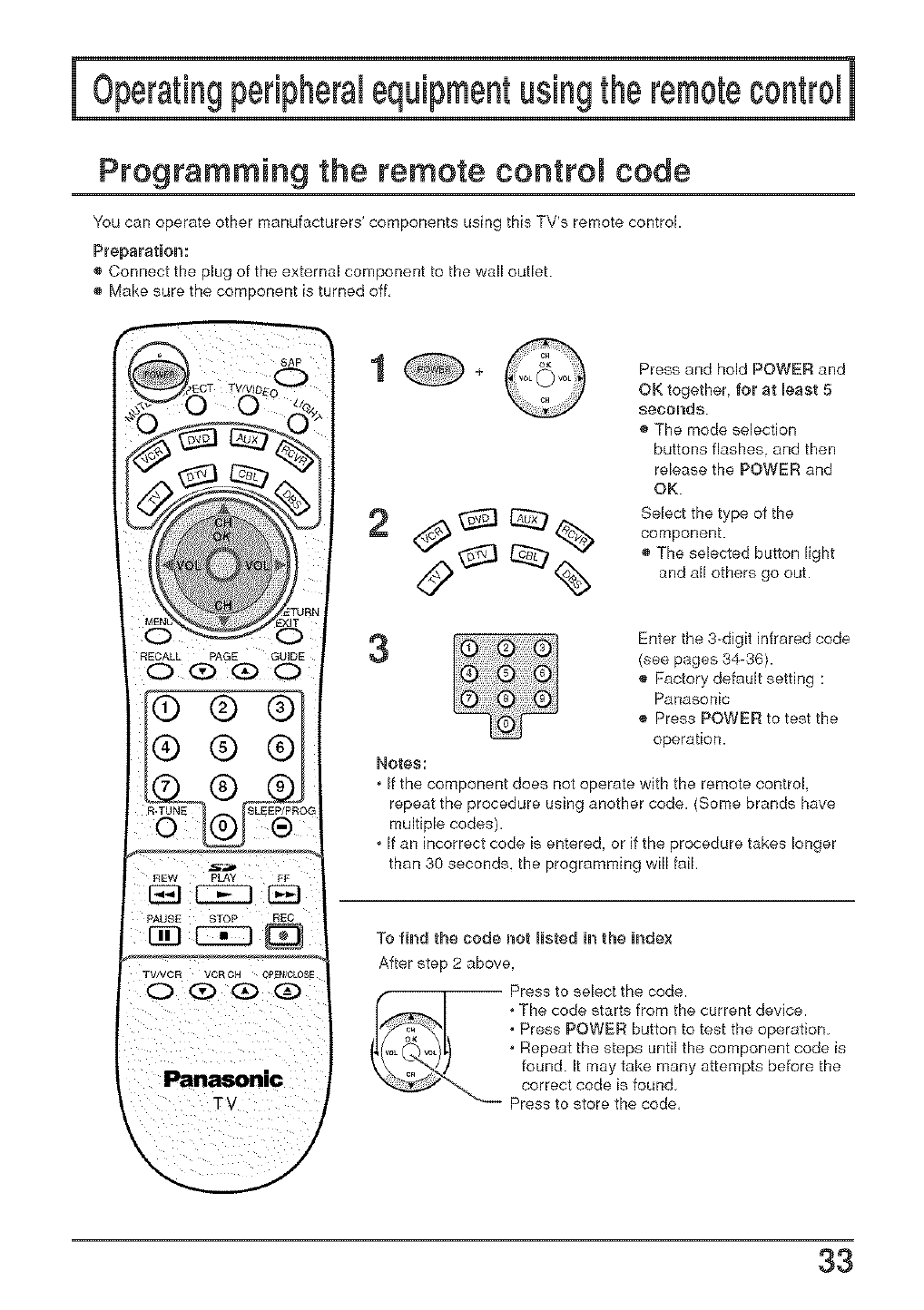
Programming the remote control code
You can operate other manufacturers' components using this TV's remote control.
Preparation:
Connect the plug of the external component to the wall outlet.
® Make sure the component is turned eff,
RECALL PAGE GUIDE
® ®®
® ®®
Panasonic
TV
/
1
2
Press and hold POWER and
OK together, for at least 5
eeeorlde
® The mode selection
buttons flashes, and then
release the POWER and
OK
Select the type ef the
component.
® The selected button light
and all ethers go eut.
Enter the 3 digit infrared code
(see pages 34-36).
® Faclory default setting :
Panasonic
® Press POWER to test the
operation.
Notes:
,If the component does not operate with the remote control,
repeat the procedure using another code. (Some brands have
multiple codes).
,If an incorrect code is entered, or if the procedure takes longer
than 30 seconds, the programming will fail.
To find the code not lusted in the Uncle×
After step 2 above,
_ ress to select the code.
,The code starts from the current device.
,Press POWER button to test the operation.
,Repeat the steps until the component code is
found. It may take many attempts before the
correct code is feun&
Press to store the code,
33
Operating petiphetam equipment using the remote conttom
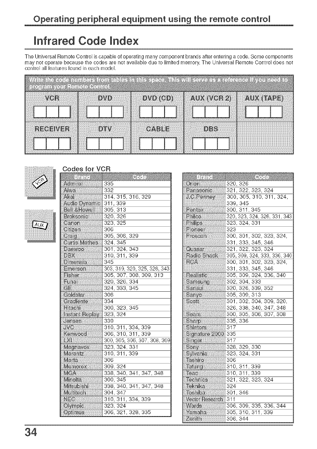
nfrared Code nde×
The Universal Remote Control is capable o1 operating many component brands af[er er_tedng a code, Some components
may not operate because the codes are not available due to limited memory The Universal Remote Control does not
control all features found irl each model,
34
_i_ii_!i_!_iiiiiiiiiiiiiiiiiiiiiiiiiiiiiiiiiiiiiiiiiiiiii
332
314,315,316,329
311,339
305,313
320,326
323,325
308
305,308,329
324.345
301,324,343
310,311,339
345
303,319,320,325,328,343
305,307,308,309,313
320,326,334
324,333,345
306
334
300,323.345
323,324
339 335,
310,311,334, 339
308,310,311,339
300,305,308.307.308.30#
323,324.331
310, 311.339
306
309.324
338,340,341,347,348
300,345
338,340,341,347,348
304,347
310,311.334.339
323,324
308,321,328,335
320, 326
321,322, 323, 324
300 305. 310. 311. 324.
339. 345
300, 311. 345
320 323. 324 328. 331 343
323, 324, 331
323
300. 301. 302. 323. 324.
331333345348
321,322, 323, 324
305 309 324 333. 336 340
300, 301,302, 323, 324,
331,333, 345, 348
305. 309. 324. 338. 340
302, 304, 333
320, 326, 339, 352
305, 309, 313
300. 305. 306. 307. 308
336
317
335
317
328, 329, 330
323, 324, 331
308
310, 311. 339
310, 311,339
321,322, 323, 324
324
301,348
311
306, 309. 335. 336. 344
305, 310. 311 339
306. 344
Operating peripheral equipment using the remote control
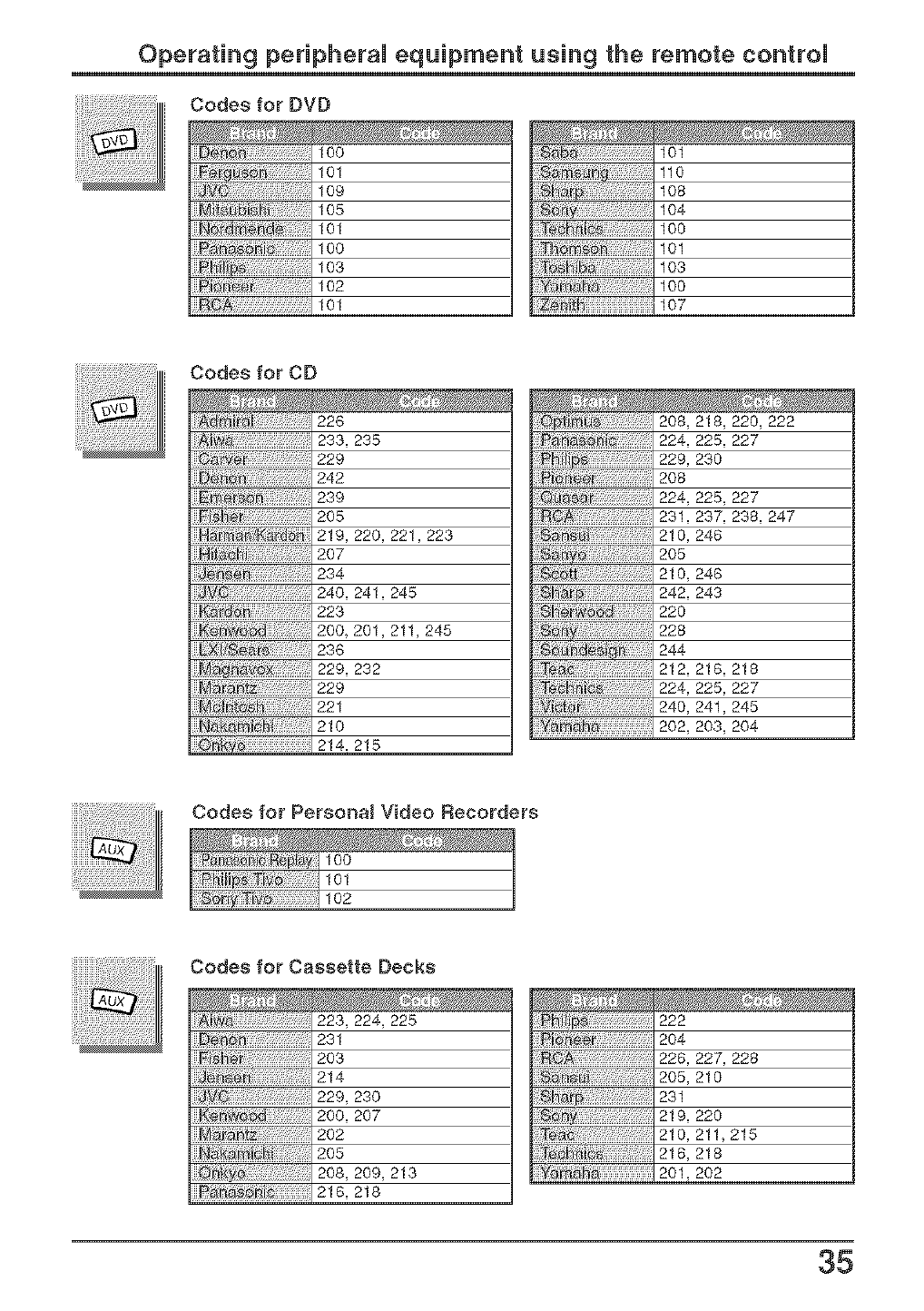
Codes for DVD
100 101
101 110
109 108
105 104
101 100
100 101
103 103
102 100
101 107
Codes for CD
226
233, 235
229
242
239
205
H _rrJr_ _ _ 219, 220, 221, 223
207
234
245
223
200 201. 211, 245
236
229, 232
229
221
210
214. 215
208, 218, 220, 222
224, 225, 227
229, 230
208
224, 225, 227
231, 237, 238, 247
210, 246
2O5
210, 248
242, 243
220
228
244
212, 218, 218
224, 225, 227
240, 241, 245
202, 203, 204
Codes for Personal Video Recorders
100
101
102
Codes for Cassette Decks
223,224,225
231
203
214
229, 230
200, 207
202
205
208,209,213
216, 218
Teh_i_:
222
204
228,227,228
205, 210
231
219, 220
210, 211,215
216, 218
201,202
35
Operating peripheral equipment using the remote control
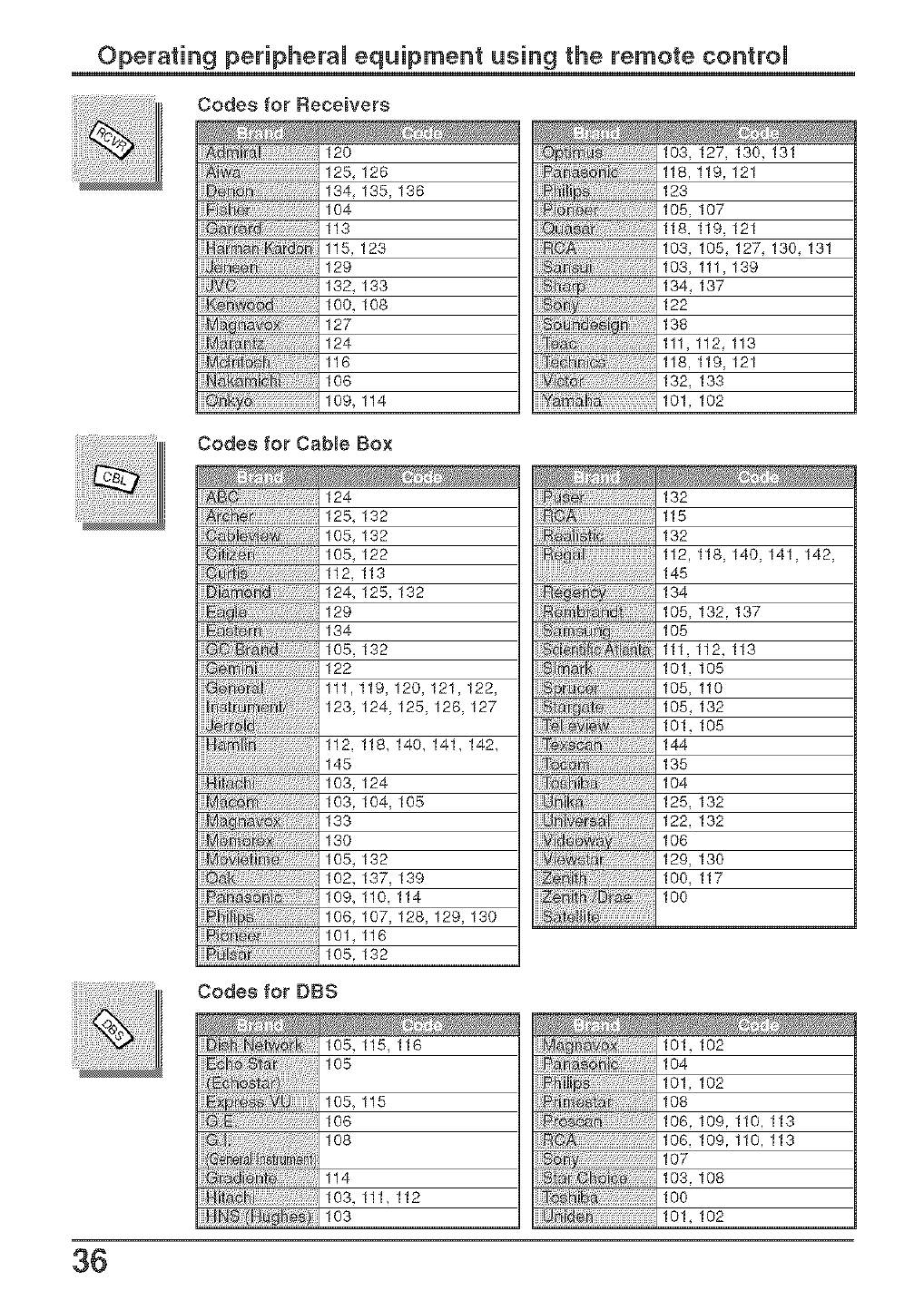
Codes for F_eceivers
ii!!
120
125,126
134,135,136
104
113
115,123
129
132,133
100,108
127
124
116
106
109,114
Codes for Cable Box
103,127,130,131
118,119,121
123
105,107
118,119,121
103,105,127,130,131
103,111,139
134,137
122
138
111,112,113
118,119,121
132,133
101,102
124
125,132
105,132
105,122
112,113
124,125,132
129
134
105,132
122
111,119,120,121,122,
123,124,125,126,127
112,118,140,141,142,
145
103.124
103.104,105
133
130
105,132
102,137,139
109,110,114
106,107,128,129,130
101,116
105.132
Te_;;;;;
132
115
132
112,118,140,141,142,
145
134
105,132.137
105
111,112,113
101,105
105,110
105,132
101,105
144
135
104
125,132
122,132
106
129,130
100,117
100
Codes for DBS
105,115,116
105
105,115
106
108
114
103,111,112
103
101,102
104
101,102
108
106.109.110.113
106,109.110.113
107
103.108
100
101,102
36
Operating peripheral equipment using the remote control
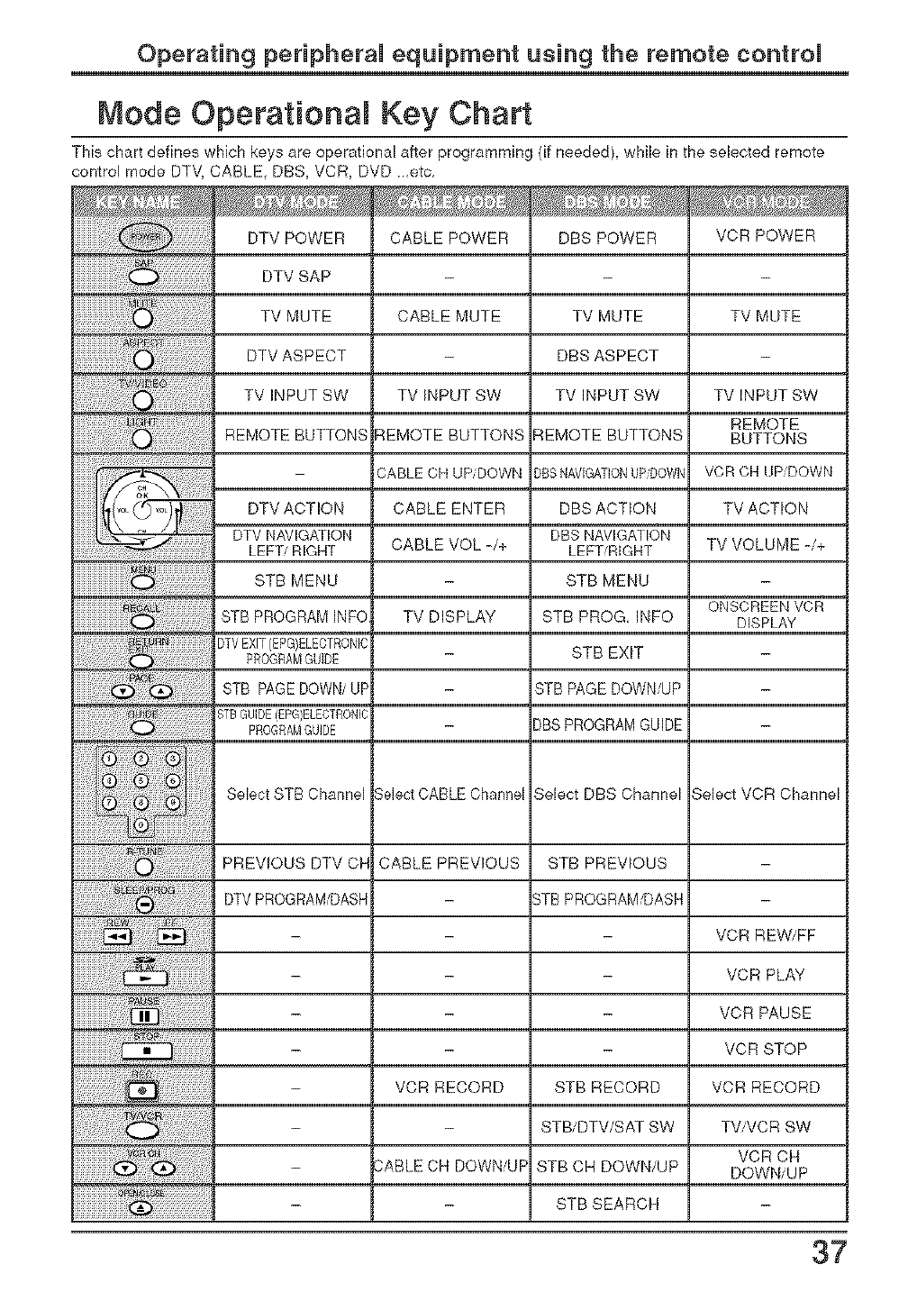
Node Operational Key Chart
This chart defines which keys are operational after programming (if needed), while in the selected remote
control mode DTM. CABLE, DBS, VCR, DVD ..,etc,
DTV POWER
DTV SAP
TV MUTE
DTV ASPECT
TV INPUT SW
REMOTE BUTTONS
CABLE POWER
CABLE MUTE
DBSPOWER VCR POWER
TVINPUTSW
REMOTE BUTTONS
CABLECHUPiDOWN
CABLE ENTER
CABLEVOL-/+
TV MUTE
DBS ASPECT
TV INPUT SW
_EMOTE BUTTONS
)BSNAVIGATIONUP_OWN
DBS ACTION
DBS NAVIGATION
LEFTiRIGMT
STB MENU
STB PROG, INFO
STB EXIT
BTB PAGE DOWN/UP
)BS PROGRAMGUIDE
TV MUTE
TVINPUT SW
REMOTE
BUTTONS
VCRCHUPiDOWN
TV ACTION
TVVOLUME-/+
DTV ACTION
DTV NAVIGATION
LEFT/RIGHT
STB MENU
ONSCREEN VCR
STB PROGRAM INFO TV DISPLAY DISPLAY
}TVEXIT(EPG)ELECTRONIC
PROGRAMGUIDE
STB PAGEDOWN/UP
_TBGUIDE(EPG)ELECTRON]C
PROGRAMGUIDE
Select STB Channel Select CABLE Channel 3elect DBS Channel Select VCR Channel
PREWOUS DTV OH CABLE PREVIOUS STB PREWOUS
DTV PROGRAMiDASH _TB PROGRAM/DASH
- - VCR REW/FF
- - VCR PLAY
- - VCR PAUSE
- - VCR STOP
- VCR RECORD STB RECORD VCR RECORD
- STB/DTV/SAT SW TV/VCR SW
VCR CH
- 3ABLE CH DOWN/UF STB CH DOWN/UP DOWN/UP
- STB SEARCH
37
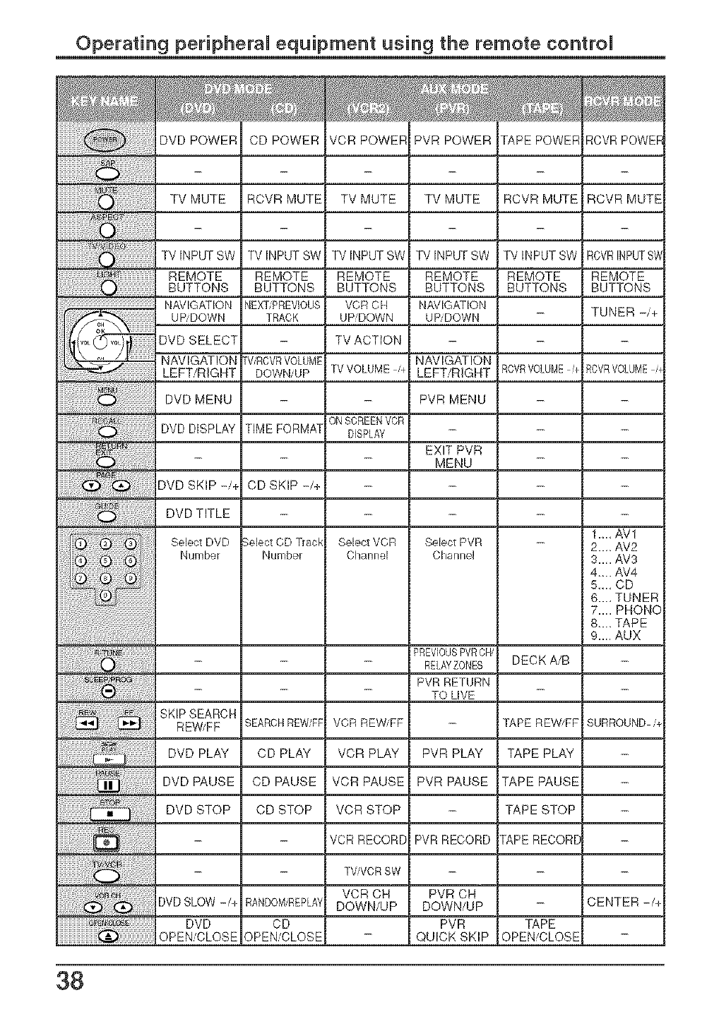
Operating peripheral equipment using the remote control
TV INPUT SW
REMOTE
BUTTONS
NAVIGATION
UP/DOWN
DVD SELECT
NAVIGATION
LEFT/RIGHT
DVD MENU
TV INPUT SW
REMOTE
BUTTONS
NEXTPREVIOUS
TRACK
[ViRCVRVOLUME
DOWN/UP
TIME FORMA[
CD SKIP -/+
:_elect CD T_ac_
Number
TV INPUT SW
REMOTE
BUTTONS
VCR CH
UP DOWN
TV ACTION
TVVOLUME /+
ONSCREENVCR
DISPLAY
Select VCR
Channel
TV INPUT SW
REMOTE
BUTTONS
NAVK'_ATION
UP F)OWN
TV INPUT SW
REMOTE
BUTTONS
RCVRVOLUME+
RCVRINPUTS_
REMOTE
BUTTONS
TUNER -/+
NAVIGATION
LEFT/RIGHT RCVRVOLUME/
PVR MENU
DVD DISPLAY
EXIT PVR
MENU
DVD SKIP -/+
DVD TITLE
1.,., AV1
Select DVD Select PVR 2.., AV2
Number Channel 3..,. AV3
4-. AV4
5,,.,CD
6..., TUNER
7... PHONC
8,_, TAPE
9..,, AUX
PREVIOUSPVRCH,
- RELAYZONES DECK A/B
PVR RETURN
TO LIVE
SKIP SEARCH
REWiFF SEARCHREWFF VCR REWiFF TAPE REW'FF SURROUND/_
DVD PLAY CD PLAY VCR PLAY PVR PLAY TAPE PLAY
DVD PAUSE CD PAUSE VCR PAUSE PVR PAUSE TAPE PAUSE
DVD STOP CD STOP VCR STOP TAPE STOP
VCR RECORD PVR RECORD rAPE RECORE
TVNCRSW
VCR CH PVR CH
DVDSLOW -/+ RANDOMREPLA_DOWN/UP DOWN/UP - CENTER -/-_
DVD CD PVR TAPE
OPEN/CLOSE OPEN/CLOSE - QUICK SKIP OPEN/CLOSE
38
IVianuemde instrucciones [Resumen]
Esdmado cliente de Panasonic
Bienve_zido a la /_mzi/ia de c/ientes de Panaso_zic.
EsT_eramos sinceJ'amente que di,_¢_ute durante muchos a6os de su _zuevo te/evisoJ"
LCD.
Para ob_ener el m_ximo ben(i_Tcio de su ap_lrato, lea estas i_strucuio_es antes
de hater cua/quier ajuste, y gu_°de/as para podeJ" uH/izarlas uomo re[_J'encia
en e/futuro_
Guarde tclmbidn el reuibo de su uomprcl, y anote el n_mero de/mode/o y e/
n_mero de serie de su aparam en e/espacio provism e_ /a cubierta posterior de
e,g't(4s instruc( iones.
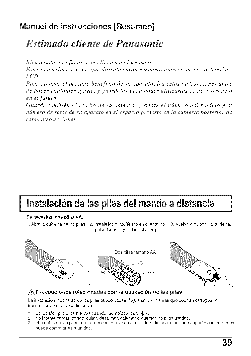
mnstalaci6nde las pilas del mandoa distancia
Se necesitan dos pilas AA,
1. Abra la cubierta de,las pilas, 2 Instale ]as pi]as. Tenga en cuenta ]as 3. Vue]va a colocar la cubierta.
po]aridades (+ y -) al instalar ]as pi]as.
Dos pilas tamafio AA
\
/K Precauciones reJacionadas con _a utiHzaci6n de las pHas
La instalaci6n incorrecta de las pilas puede causar fugas en las mismas que podr[an estropear el
transmisor de mando a distancia.
1. Utilice siempre pilas nuevas cuando reemplace las viejas
2 No intente cargar, cortocircuitar, desarmar, calentar o quemar las pilas usadas,
3, El cambio de las pilas resulta necesario cuando el mando a distancia funciona esporSdicamente o no
puede controlar esta unidad.
39
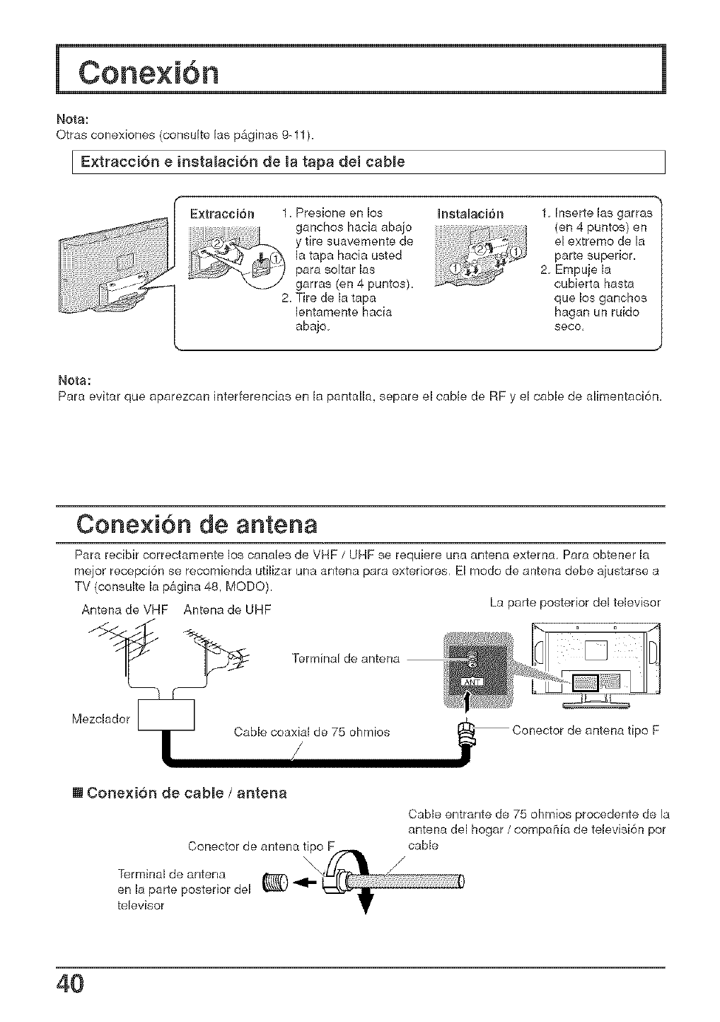
Nora:
Otras conexiones (consulte las p&ginas 9-11 ).
I Extracci6n e insta_aci6n de la tapa det cable
Extracci6n 1. Presione en los h_stalad6n
ganchos hacia abajo
y tire suavemente de
la tapa hacia usted
para soltar las
garras (en 4 puntos).
2. Tire de h tapa
lentamente hacia
abajo
1. Inserte hs garras
(en 4 puntos) en
el extremo de la
parte superior.
2. Empuje la
cubierta hasta
que los ganchos
hagan un ruido
seco,
Nots:
Para evitar que aparezcan interferencias en la pantalh, separe el cable de RF y el cable de alimentaci6n,
Conexi6n de antena
Para recibir correctamente los canales de VHF /UHF se requiere una antena externa Para obtener la
mejor recepd6n se recomienda utilizar una antena para extedores, El modo de antena debe ajustarse a
TV (consulte la p&gina 48. MODO).
Antena de VHF Antena de UHF La parte posterior del televisor
"_ Terminal de antena
Mezdador
Cable coaxial de 75 ohmios -- Conector de antena tipo F
[] Conexion de cable /antena
Conector de antena fipo F
Terminal de antena
en la parte posterior del
televisor
Cable entrante de 75 ohmios procedente de la
antena del hogar /compaCffa de televisi6n pot
cable
/
4O
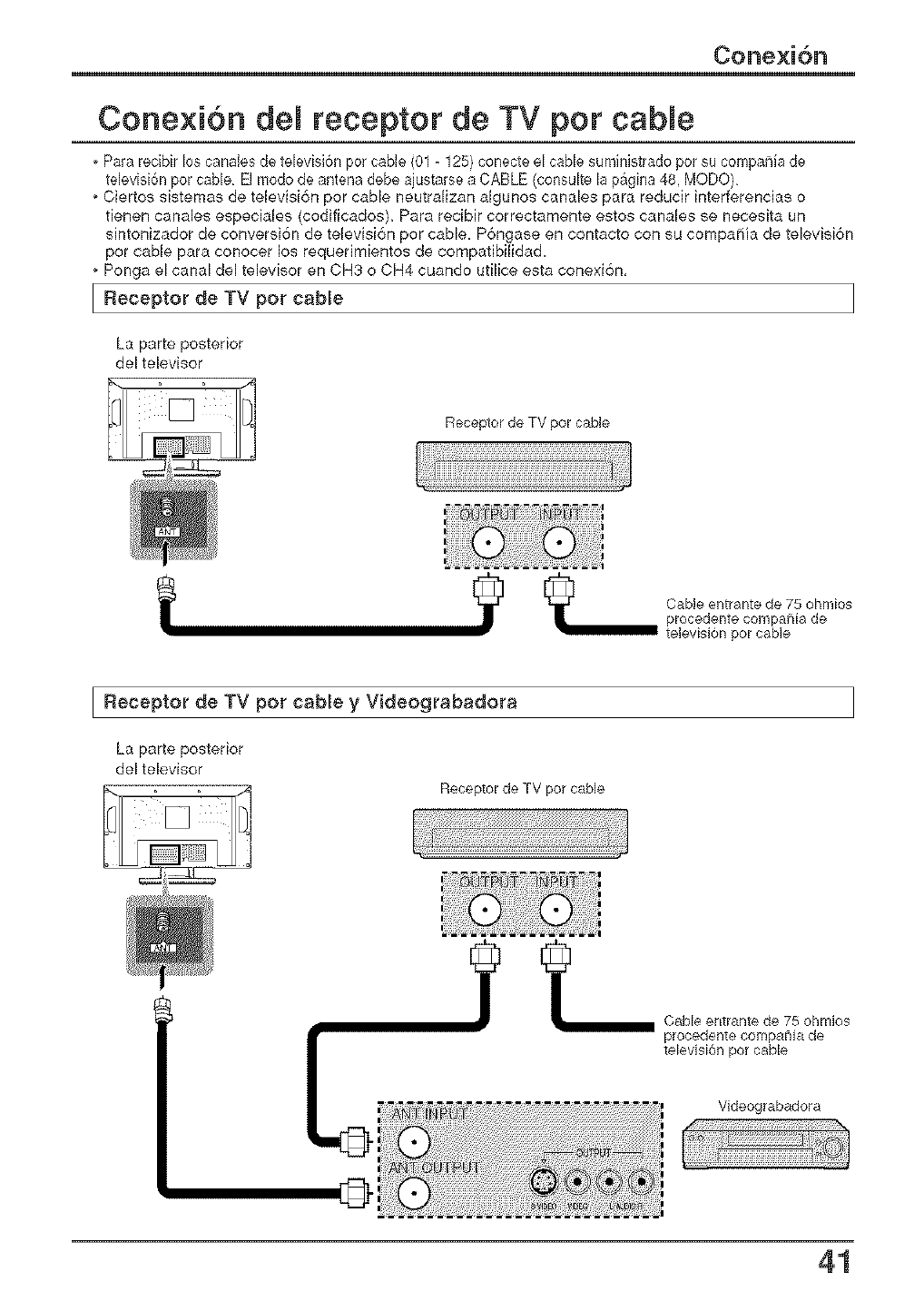
Cone×ion del receptor de TV pot cable
, Para recibir los canabs de televisi6n pot cable (01 -125) conecte el cable suministrado pot su compania de
televisi6n por cable El modo de antena debe ajustarse a CABLE (consuke Is p_gina 48, MODO)
Ciertos sisternas de televisi6n por cable neutralizan algunos canales para reducir interferencias o
fienen canales especiales (codificados), Para recibir correctamente estos canales se necesita un
sintonizador de conversi6n de televisi6n por cable. P6ngase en contacto con su cornpaffia de televisi6n
pot cable para conocer los requerimientos de compatibilidad.
Ponga el canal del televisor en CH3 o CH4 cuando ufilice esta conexi6n,
I Receptor de TV cablepot
La parte posterior
del televisor
Receptor de TV pot cable
CaMe entrant÷ de 75 ohmios
I Receptor pot y Videograbadora
de TV cable
La parte posterior
del televisor
Receptor de TV pot cable
Cab[÷ entrante de 75 ohmios
procedente compania de
televisi6n pot cable
Videograbadora
©
41
Contro es basicos
ControJ remoto iJuminado
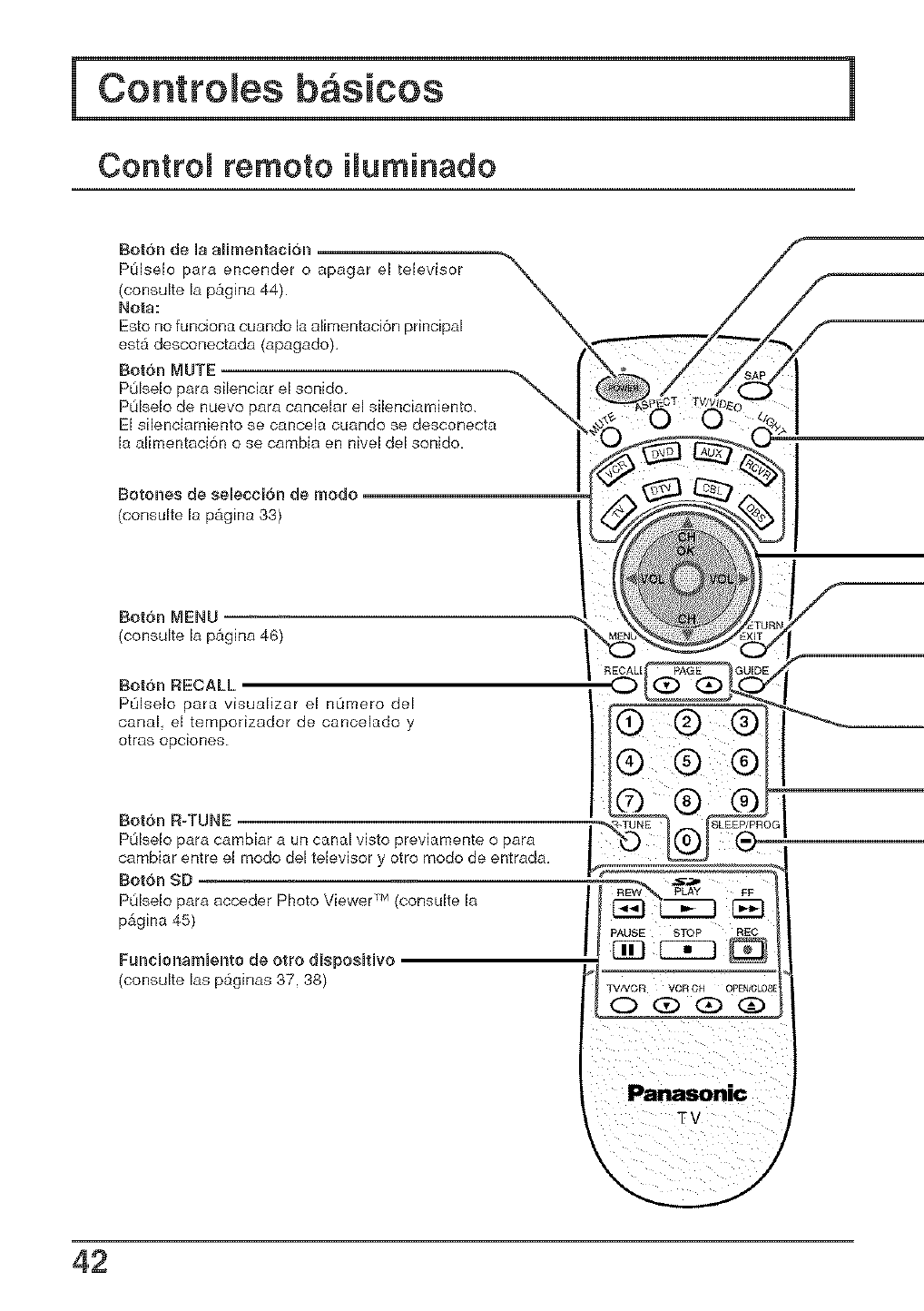
Bot6n de la aHmentaci6n
POlselo para encender o apagar el televisor
(consuke la p_gina 44).
No_a:
Esto no funciona cuando la alimentaci6n principal
est_ desconectada (apagado),
Bot6n MUTE
PL_lselopara silenciar el sonido.
POIselo de nuevo para cancelar el s[lenciarniento,
El silenciamiento se cancela cuando se desconecta
M alimentaci6n o se cambia en nivel del sonido,
Botones de seleccJ6n de modo
(consulte la p&gina 33)
Bot6n MENU
(consuke la p&gina 46)
Bot6n RECALL
POlselo para visuafizar el nOmero del
canal el temporizador de canceMdo y
otras opciones.
Bot6n R-TUNE
POlselo para camb[ar a un canal visto previamente o para
cambiar entre el modo deJtelevisor y otro modo de entrada.
Bot6n SD
POlselo para acceder Photo Viewer TM(consulte la
p&gina 45)
FuncBonamBento de otto dJsposBtUvo
(consulte [as p_ginas 37.38)
\/
42
Controles basicos
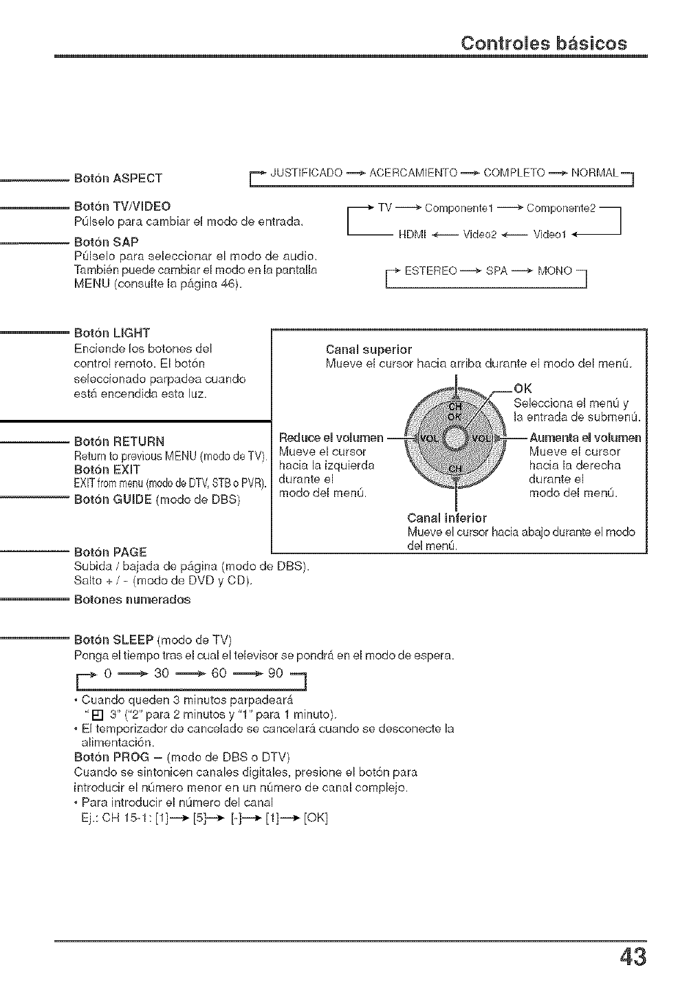
Bot6n ASPECT r JUSTIFICADO _ ACERCAMIENTO _ COMPLETO _ NORMAL==]
Rot6n TV/VIDEO
POlselo pare cambiar el mode de entrada,
Rot6n SAP
P0lselo pare seleccionar el mode de audio,
Tambi6n puede cembiar el modo en la pentalla
MENU (consulte la p&gina 46). EsTE Eo-- MONOq
Rotbn LIGHT
Enciende los botones del
control remoto. El bot6n
seleccionado parpadea cuando
est& encendida esta luz
Rotbn RETURN
Rot6n GUIDE (mode de DBS)
Canal superior
Mueve el cursor hacia arriba durante el mode del men0
Reduce el volumen ===
Mueve el cursor
hacia [a izquierda
durante e[
mode de[ men0,
Dot6n PAGE
Subide /baiada de p&gina (mode de DBS).
Salto + /- (mode de DVD y CD),
BOtches numersdos
Selecciana el men0 y
la entrada de submenu.
Mueve el cursor
hacia la derecha
durante el
mode del men0.
Canal h#erier
Mueve el cursor hacia abajo durante el mode
del men&
Rot6n SLEEP (mode de TV)
Ponga el tiempo tras el cual el televisor se pondr_ en el mode de espera.
[..._ 0 m----_ 30 m----_ 60 m----_ 90 ._
,Cuando queden 3 minutos parpadear_
"[] 3" ("2" pare 2 minutos y "1" pare 1 minuto)
,El temporizador de cancelado se cancelara cuando se desconecte la
alimenteci6n.
Botch PROG - (modo de DBS o DTV)
Cuando se sintonicen canales digitales, presione el bot6n pare
introducir el n0mero menor en un nOmero de canal complejo.
,Pare introducir el n0mero del canal
Ej.: CH 15-1: [1]i-_ [5]i-_ [_]i._ [1]i__ [OK]
43
Controtes basicos /Cone×ion /descone×ion de Ja almentacidn
Aparato principal
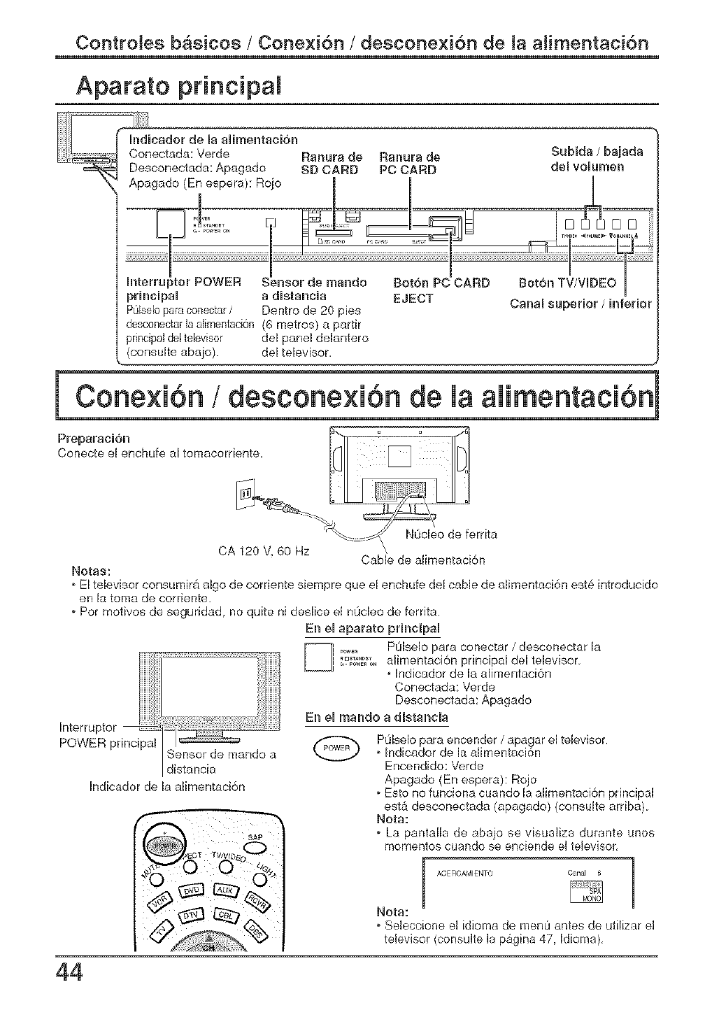
Indicador de Jaalimentacidn
Conectada: Verde Rsnsra de Ranurs de
Desconectada: Apagado SD CARD PC CARD
Subids /bsisds
del volurnen
prh_cipsl s distsncis
Dentro de 20 pies
desconectsrD slimentacidn (6 metros) a parfir
del panel delantero
(consulte abajo), del televisor.
EJECT Canal superior /inferior
Conecte el enchufe _o
a omaco r en e []
deferrit=
CA 120 V, 60 Hz CaNe de alimentacidn
Rotss:
o El televisor consumir_ algo de corriente siempre que el enchufe del cable de alimentacidn est6 introducido
en la toms de corriente.
o Per motives de seguddad, no quite ni deslice el n0cleo de ferrita.
Interrupter
POWER principal Sensor de mando a
distancia
Indicador de la alimentacidn
En el sparsto principal
...... POiseIo pars conectar, desconectar la
1%_T2_g_;"alimentacidn principal del televisor.
. Indicador de la alimentacidn
Conectada: Verde
Desconectada: Apagado
En el msndo a distsncis
POlselo pars encender /apagar el televisor.
o Indicador de la alimentacidn
Encendido: Verde
Apagado {En espera): Rojo
o Esto no funciona cuando la alimentaci6n principal
est_ desconectada (apagado) (consuite arriba).
Rots:
oLa pantalD de abajo se visualiza durante unos
mementos cuando se enciende el televisor
ACERCAMIENTO Canal 6
Rots:
o Seleccione el idioms de menu antes de utilizar el
televisor (consulte la pagina 47, Idioms),
44
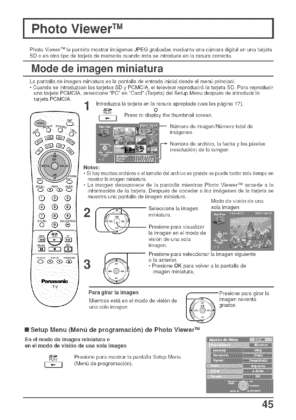
Photo Viewer TM le permite mostrar im_genes JPEG grabadas mediante una c_mara digital en una tarjeta
SD o en otto fipo de tarjeta de memoria cuando 6sta se introduce en la ranura correcta.
Mode de imagen miniatura
La pantalla de imagen miniatura es la pantalla de entrada initial desde el menO principal.
o Cuando se introduzcan las tarjetas SD y PCMCIA, el televisor reproducir_ la tarjeta SD_ Para reproducir
una tarjeta PCMCIA, seleccione "PC" en "Card" (Tarjeta) del Setup Menu despu6s de introducir la
tarjeta PCMCIA
o I
1Introduzca Ix tarjeta en la ranura apropiada (vea las p&gina 17),
_ O
pLAy
Press to display the thumbnail screen.
N0mero de imageniNOmero total de
im_genes
Nombre de archivo, la fecha y los pixeles
(resoluci6n) de la iamgen
TV
Notas:
.Si hay muchos archivos o el tamaflo del archivo es grande se puede tardar m&s tiempo en
mostrar [a imagen miniatura.
.La imagen desaparece de la pantaJla mientras Photo Viewer r_4accede a 15
informaci6n de la tarjeta_ Despu6s de acceder alas im&genes de la tarjeta se
muestra una pantalla de imagen miniatura.
Seleccione la imagen
miniatura
Modo de visi6n de una
sola imagen
Presione para visualizar
la imagen en el modo de
visi6n de una sola
imagen.
Presione para seieccionar la imagen siguiente
o la anterior.
. Presione OK para volver a la pantalla de
imagen miniatura.
Para girar la Umagen
Mientras est_ en el modo de visi6n de
una sola imagen
Presione para girar la
imagen noventa
grados
[] Setup Menu (Mene de programaci6n) de Photo Viewer TM
En el modo de irnagen mJnJatura o
en el modo de visi6n de una sola imagen
pLAy Presione para mostrar la pantalla Setup Menu
(MenL_de programaci6n)
45
!
46
!
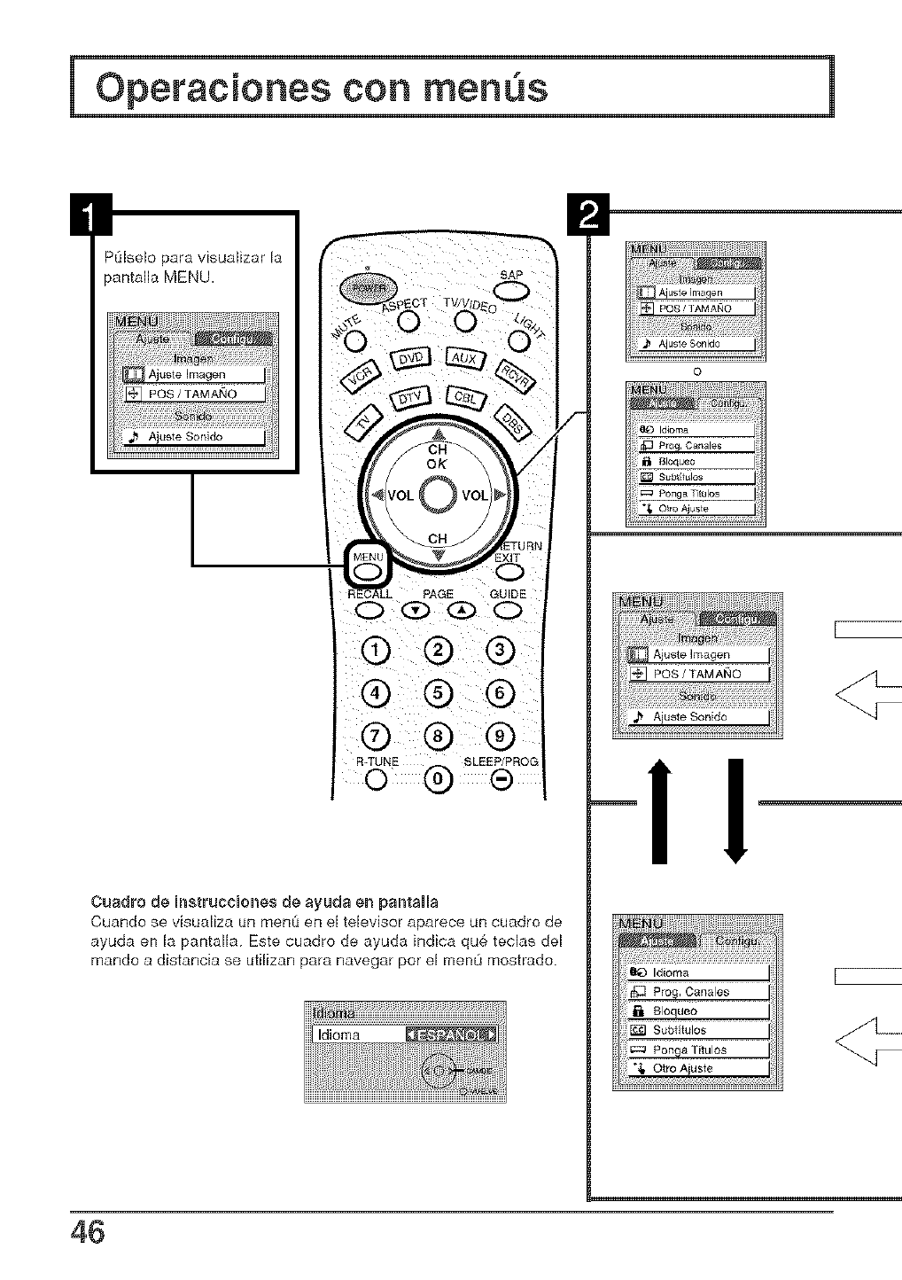
POIselo para visualizar la
pantalla MENU.
Ajuste Sonido
Io dAG&_
® ® ®
® ® ®
® ® ®
R-TUNE @ 8LEEP/PROG(_
Cuadro de JnstruccBones de ayuda en pantalJa
Cuando se visualiza un menO en el televisor aparece un cuadro de
ayuda en Ja pantaHa. Este cuadro de ayuda indica qu6 teclas del
mando a distancia se utilizan para navegar por el menO mostrado.
Operaciones con menus
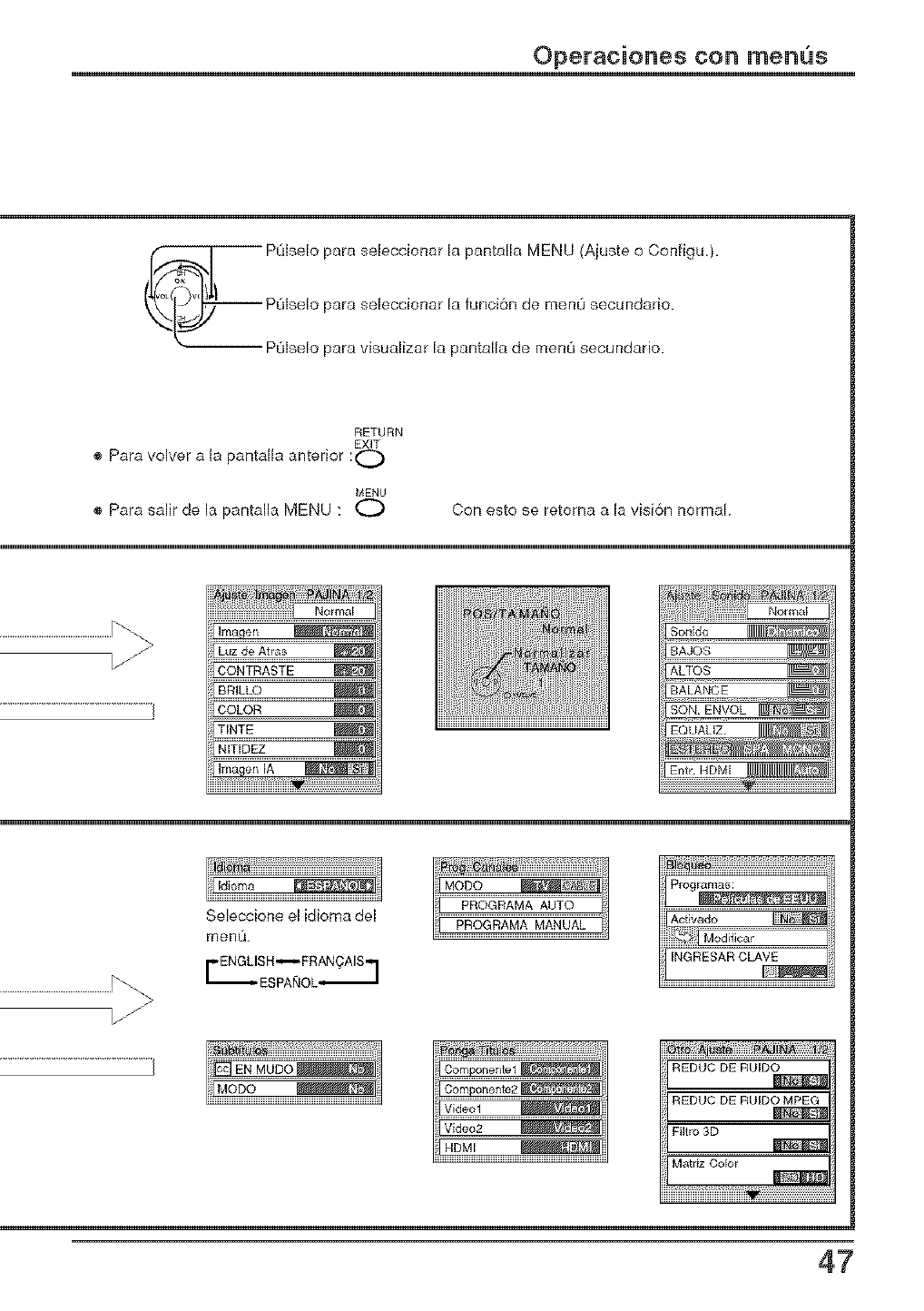
_ PQbelo para sebccionar la pantalla MENU (Ajuste o Configu.).
I PL_Iselo para seleccionar la funci6n de menO secundario.
(_(_ PL_Iseio para visuaJizar la pantaiia de menO secundario
RETURN
EXiT
® Para volver a la pantalla anterior :t"--_
MENU
® Para salir de la pantafla MENU : O Con esto se retorna a la visi6n normal
Luzde Arras
CONTRASTE
BRILLO
COLOR
TINTE
NITIDEZ
Imager/IA Entr HDMI
Seleccione el idioma del
menu
FENGLISH--FRANOAIS.,
ESPA_OL,J
Activado
INGRESARCLAVE
REDUC DE RUIDO
REDUC DE RUIDO MPEG
Filtro 3D
MatrlzColor
iiiii
47
Opetaciones con menus
Sintonizacion de canaies
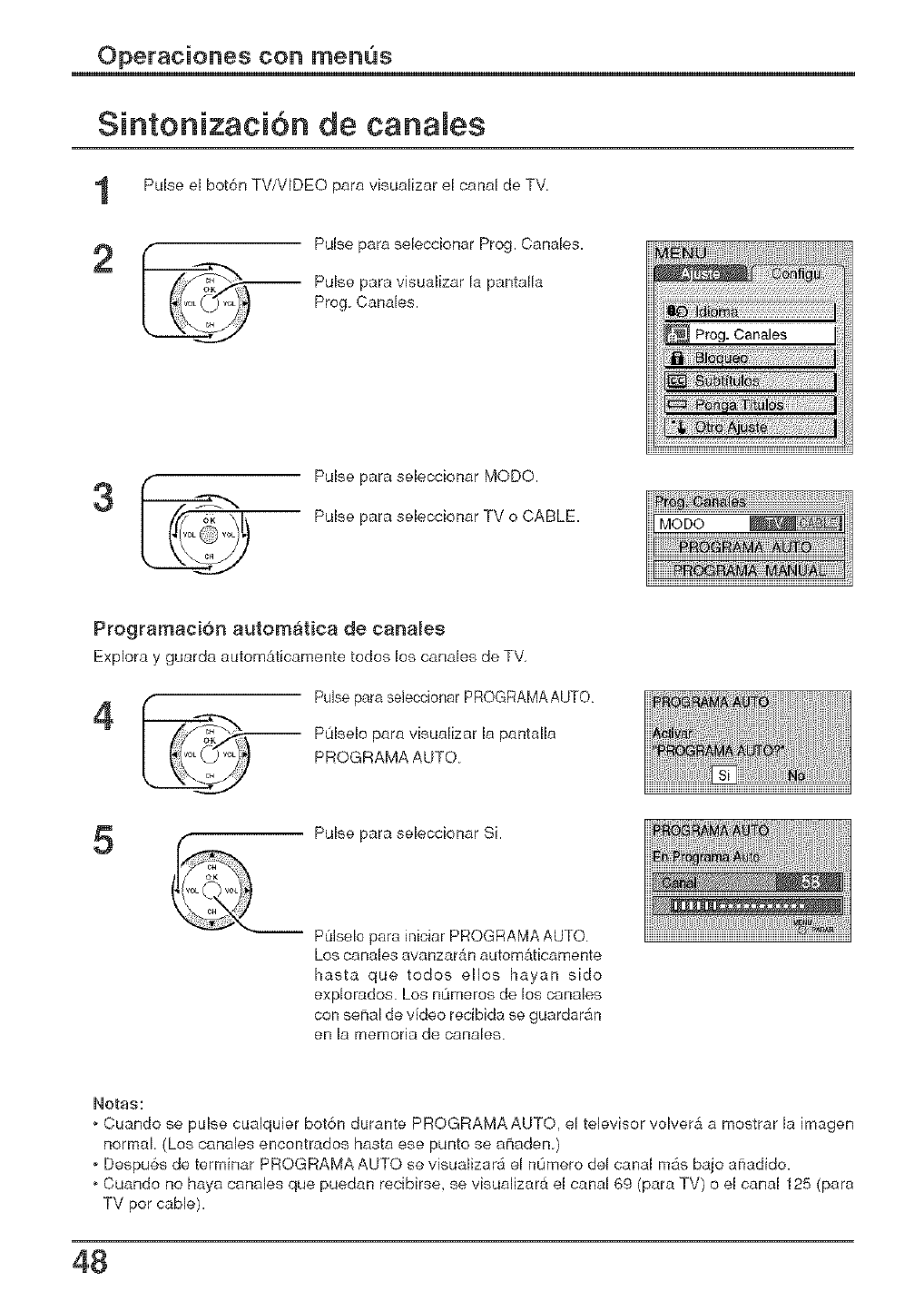
Pulse el bot6n TV/VIDEO para visualizar el canal de TV
2 Pulse para se[eccionar Prog. Canales.
Pulse para visualizar 15pantalla
Prog Canales.
Pulse para seleccionar MODO.
Pulse para seleccionar TV o CABLE.
Programacion automatica de canales
Explora y guarda autom&ticamentetodos los canales de TV,
4Pulse para seleccionar PROGRAMAAUTO
POlselo para visualizar la pantalla
PROGRAMA AUTO.
5Pulse para seleccionar Si.
-- POIselo para Jniciar PBOGRAMA AUTO
Los canales avanzar_n automaticamente
hasta que todos ellos hayan sido
explorados. Los nOmeros de los canales
con seNal de video recibida se guardar_n
en la memoria de canales.
Notas:
Cuando se pulse cualquier bot6n durante PROGRAMA AUTO, el televisor volver& a mostrar la imagen
normal (Los canales encontrados hasta ese punto se a_aden )
o Despu6s de terminar PROGRAMA AUTO se visualizar_ el nOmero del canal m_s bajo a_adido.
, Cuando no haya canales que puedan recibirse_ se visualizar_ el canal 69 (para TV) o el canal 125 (para
TV pot cable).
48
Operaciones con menus
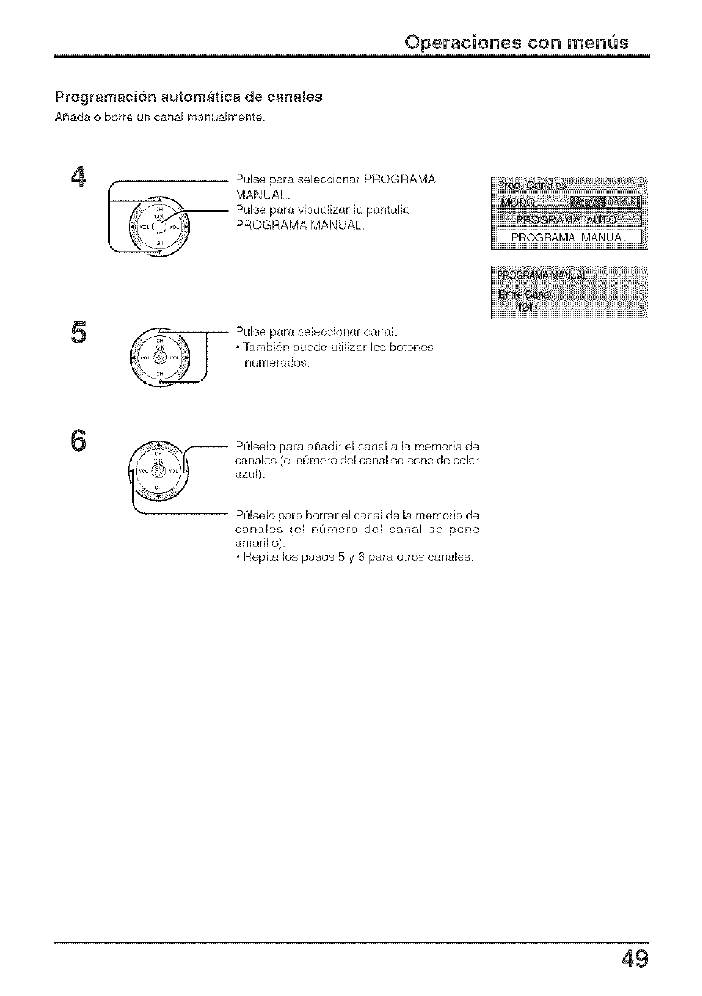
Programaci6n automatica de canaies
Aflada o borre un canal manuaimente
4Pulse para seleccionar PROGRAMA
MANUAL.
Pulse para visualizar [a pantalla
PROGRAMA MANUAL,
5Pulse para seleccionar canal.
. Tambi6n puede utilizar los botones
nLJmerados.
6POlse[o para aCladir el canal a [a memoria de
canales (el nQmero de[ canal se pone de color
azu[).
POlselo para borrar e[ canal de la memoria de
canales (el nQmero del canal se pone
amarillo).
. Repita los pasos 5 y 6 para otros canales.
49
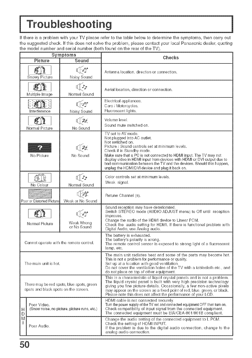
ff there is a problem with your TV please refer to the table below to determine the symptoms, then carry out
the suggested check If this does not solve the problem, please contact your local Panasonic dealer quoting
the model number and serial number (both found on the rear of the TV).
Snowy Picture
Multiple Image
Interference
Normal Picture
No Picture
Symptoms
PBcture Sound
Noisy Sound
Normal Sound
Noisy Sound
No Sound
No Sound
<,,
Normal Sound
W_ak or No Sound
Weak Wrong
or No Sound
Checks
Antenna location, direction or connection
Aerial location, direction or connection
Electrical appliances
Cars /Motorcycles
Fluorescent lights
Volume level
Sound mute switched on
TV set to AV mode
Nat plugged into AC outlet
Not switched on
Picture /Sound controls set at minimum levels
Check it in Standby mode
Make sure 1hat a PC is not connected 1o HDMi input. The TV may not
display video in HDMI input from devices with RDMI or DVI output due 1o
bad communication between the TV and the devices. Should this happen,
unplug the HDMI/DVl device and plug it back on,
No Colour
Retune Channel (s)
Poor or Distorted Pictur_
Color controls set at minimum levels
Weak signal
Sound reception may have deteriorated.
Switch STEREO mode {AUDIO ADJUST menu) to Off until reception
improves
Change the audio of the HDMI device to Linear PCM
Chock the audio setting for HDMI If there is functional problem with
Digital Audio, use Analog audio
The battery is exhausted.
The battery's polarity is wrong
The remote control sensor is exposed to seong light of a tklorescent
lamp, mc
Normal Picture
Cannot operate with tho remote control
The main unit radiates heat and some of the parts may become hot
This is not a problem for performance or quality
The main unit is hot Set up at a location with good ventilation
Do riot cover the ventilation holes of th= TV with a tablecloth etc, and
do not place on top of other equipment
This is a characteristic of liquid crystal panels and is not a problem
Tbe liquid crystal panel is built with very high precision technology
There may be red spots, blue spots, green giving you fine picture details Occasionally, a few non active pixels
spots and black spots on the screen may appear on the screen as a fixed point of red, blu=, green, or black
Please note this do_s riot affect the performance of your LCD
RDMI cable is riot connected securely
Poor Video. Turn the power supply of the TV set and connectedequipment OFF then turn on
H (Snow noise, no picture, picture runs, etc,) Check compatibility of input signal from the connected equipment.
D The connected equipment must be EIA, CEA-861 861B compliant
M Change the audio setting of the connected equipment to LPCM
Check the setting of HDMI INPUT
Poor Audio It the problem is due to the digital audio connection, change to the
analog audio connection
5O
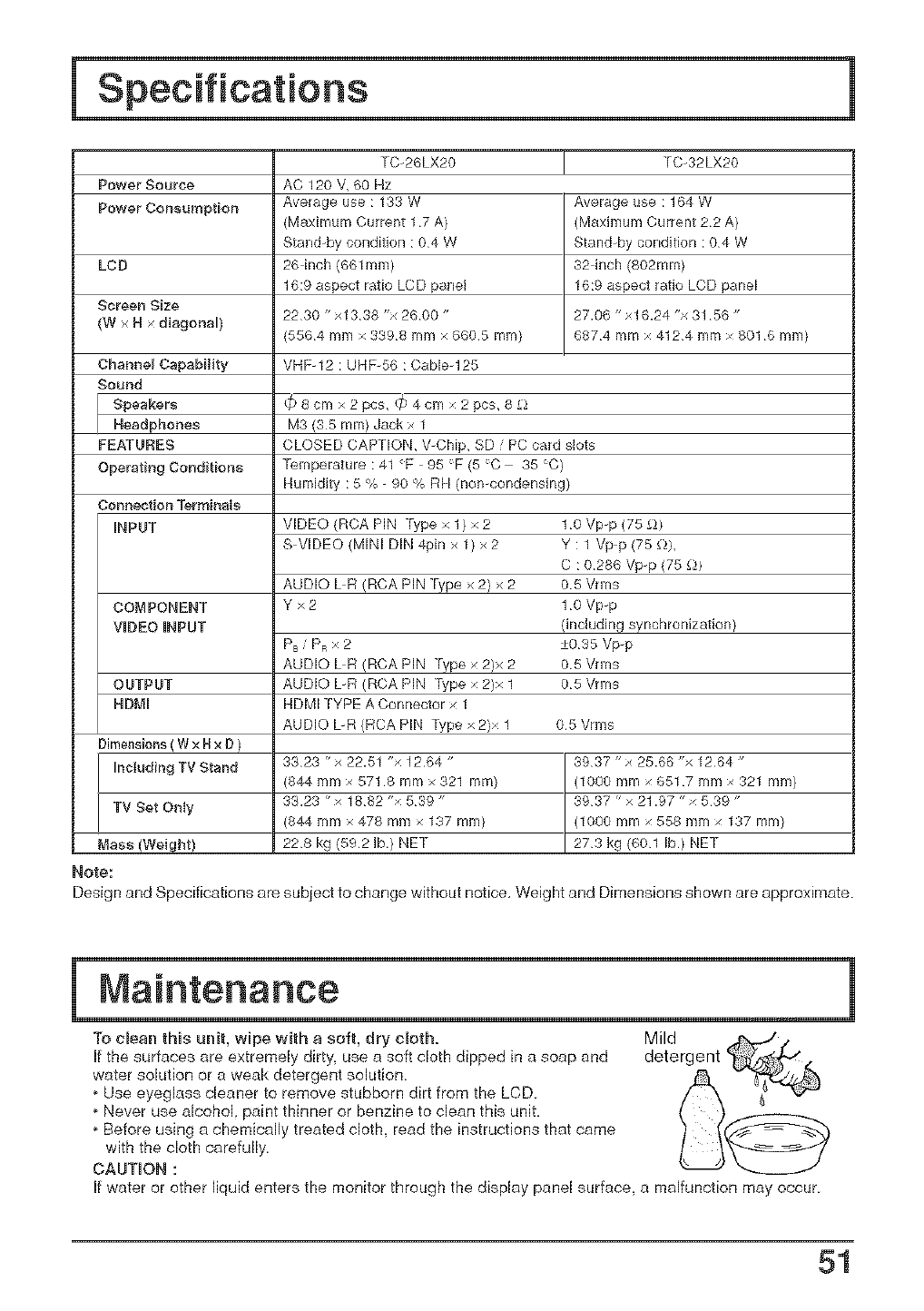
Specifications
Power Source
Power Consumption
LCD
SoreeR Size
(W × N diagonal)
Channel Capability
Sound
j peakers
Headphones
FEATURES
Operating Conditions
TC-26LX20
&C 120 V, 60 Hz
Average use :133W
OUTPUT
NDMI
26 inch (661mm)
16:9 aspect ratio LCD pane[
2230 "x1338"×2600"
5564mmx3398mmx6605mm)
VHF-12 : UHF-56 : Cab[eq 25
TC-32LX20
Average L_se: 164 W
32-inch (802mrn)
16:9 aspect ratio LCD panel
27.06 "xl 6.24 "x 31 56"
6874 mm x 4124 mm x 801 6 mIT'
_ 8 cm x 2 pcs, (_34 cm x 2 pcs, 8 £)
M3 (35 ram) Jackx 1
CLOSED CAPTION, V-CMp, SD /PC card slots
Temperature:41 F-95°F(5°C 35 C)
Humidity : 5 % 90 % RH (nomcondensing)
Connection Termi_)als
iNPUT VIDEO (RCA PIN Type x 1) x 2 1 o Vp-p (75 _-U
SW[DEO (MINI DIN 4pin x 1) x 2 Y : 1 Vp-p (75 £)),
C : 0286 Vp-p (75 £))
AUDIO UR (RCA PIN Type x 2) x 2 0 5Vrms
COMPONENT Y x 2 1 0 Vpp
VIDEO iNPUT (including synchronization)
PB/PmX 2 +035 Vp_p
AUDIO UR (RCA PIN Type x 2)x 2 05 Vrms
AUDIO UR (RCA PIN ]'ype x 2)x 1 05 Vrms
HDMI TYPE A Connector x 1
AUDIO L-R {RCA PIN iype x 2)x 1
Dimensions ( W x Hx D)
[ncludi_g TV Stand
TV Set Ot_Iy
Mass (Weight)
Note:
05 Vrms
3323 "x 22.51 "x 1264 "
344 mm x 571 8 mm x 321 mm)
33.23 "x 1882 "x 539 "
344 mmx 478 mm x 137 mm)
228 kg (5921b) NET
Design and Specifications are subject to change without notice, Weight and Dimensions shown are approximate.
To clean this unit, wipe with a soft, dry cloth. Mild
If the surfaces are extremely dirty, use a soft cloth dipped in a soap and detergent
water solution or a weak detergent solution
,Use eyeglass cleaner to remove stubborn dirt from the LCD
,Never use alcohol paint thinner or benzine to clean this unit,
,Before using a chemically treated cloth, read the instructions that came
with the cloth carefully.
CAUTION :
If water or other liquid enters the monitor through the display pane[ surface, a maffuncfion may occur
51
Customer's Record
The model number and serial number of this product can be found on its rear panel. You should
note this serial number in the space provided below and retain this book, plus your purchase
receipt, as a permanent record of your purchase to aid in identification in the event of theft or
loss, and for Warranty Service purposes,
Model Number Serial Number
Panasonb Consumer Ebctrmlies
Company, DMeimr of Mateushita
Electric Corporatimr of Amerba
One Panasonb Way Secaucus
New Jersey 07094
Panaeonb Sales Company,
Division of Matsushita Ebetrie
of Puerto Rico be. ("PSC')
Ave. 65 de Infanteria, Km 9.5
San Gabrbl Industrial Park,
Carolina, Puerto Rice 00985
Pena$oni¢ Caned8 he.
5770 Ambler Drive
Mississauga Ontario
L4W 2T3
© 2004 MatsusNta Ebctric Industrial Co ,Ltd All Rights Reserved Printed in Japan
MBS0204SO
