PARROT CK5050NEW Bluetooth Car Multimedia Module User Manual CK5050New Datasheet 1 6
PARROT Bluetooth Car Multimedia Module CK5050New Datasheet 1 6
PARROT >
Users Manual
DATASHEET Confidential Information 1/49
Parrot CK5050NEW
All in one multimedia module
Bluetooth 2.0+EDR compliant
Bluetooth 2.1+EDR available in 09Q3
Version 2.00
March 2009
FEATURES
Bluetooth 2.0 + EDR qualified module
Piconet and scatternet support
Standard single 3V3 supply
CAN, UART, I²C
2*USB 2.0 full speed Host
GPIO
Ipod chip management
Digital audio input and output
Analog audio input and output
Small size module (34,5 x 41,35 mm)
Automotive qualified
Application:
• Telephony
• Audio streaming
• USB
• Ipod management
• Internet access (through DUN)
The CK5050New integrates the latest
version of the Parrot Bluetooth stack
(Blues). Blues gives to the customer a
very high level of compatibility with most of
the phones available on the market and
provide phonebook and list
synchronization.
The CK5050New can also integrate a
version of the Parrot USB management
library (Disco). Disco manages the USB
devices, build database with metadata,
browses the compressed audio files by
artist/gender/title and play them. Disco
also supports the IPod chip through the
I²C interface.
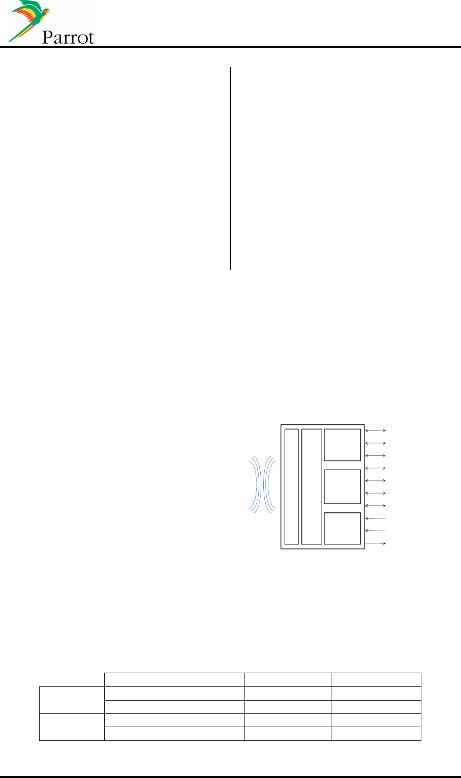
Description:
Parrot CK5050New is a low cost solution
for Bluetooth connectivity. It integrates a
large variety of interfaces for an easy
integration in most of the applications
Parrot
P5+
Flash
SDRAM
BT 2.0+EDR RF chip
Internal or external antenna
CAN
2*USB 2 Full speed Host
2*UART
I²C
I²S in*1/out*2
PCM in/out
2*Analog microphone input
Analog line in
2*Analog output
2*GPIO
Memory (Flash/SDRAM)
Vertic
al
Horizontal
Internal
antenna 32Mbits/64Mbbits
PF240023AA PF240024AA
64Mbits/128Mbbits
PF240033AA
PF240034AA
External
antenna 32Mbits/64Mbbits
PF240036AA PF240037AA
64Mbits/128Mbbits
PF240038AA
PF240039AA

DATASHEET Confidential Information 2/49
Table of contents
1
PRODUCT OVERVIEW ............................................................................................................................... 4
2
SOFTWARE SPECIFICATIONS .................................................................................................................... 6
2.1
B
LUETOOTH STACK
...................................................................................................................................... 6
2.2
B
LUETOOTH PROFILE SUPPORTED
................................................................................................................... 6
2.3
S
OFTWARE INTERFACE
................................................................................................................................. 7
2.4
M
EMORY CONFIGURATIONS
.......................................................................................................................... 7
3
ELECTRICAL SPECIFICATIONS .................................................................................................................... 8
3.1
H
ARDWARE ARCHITECTURE
........................................................................................................................... 8
3.2
P
INOUT
.................................................................................................................................................... 8
3.2.1
40 pins diagram ................................................................................................................................. 8
3.2.2
Pinout table ....................................................................................................................................... 9
3.2.3
Unconnected pins advice ................................................................................................................. 10
3.3
M
AXIMUM RATINGS
.................................................................................................................................. 11
3.4
P
OWER CONSUMPTION
(T°=-40°C
TO
+85°C) .............................................................................................. 11
3.5
E
LECTRICAL SPECIFICATIONS
........................................................................................................................ 11
3.5.1
Power pins ....................................................................................................................................... 11
3.5.2
Reset pin .......................................................................................................................................... 11
3.5.3
IO pins .............................................................................................................................................. 12
3.5.4
CAN .................................................................................................................................................. 12
3.5.5
I²C .................................................................................................................................................... 13
3.5.6
USB .................................................................................................................................................. 14
3.5.7
UART0/UART1 ................................................................................................................................. 14
3.5.8
PCM ................................................................................................................................................. 15
3.5.9
I²S .................................................................................................................................................... 16
3.5.10
Analog out ................................................................................................................................... 17
3.5.11
Line in .......................................................................................................................................... 17
3.5.12
Microphone input ........................................................................................................................ 17
3.5.13
Bluetooth radio link ..................................................................................................................... 18
3.6
R
ESET AND SUPPLY SEQUENCE DIAGRAM
....................................................................................................... 19
3.6.1
Switching ON ................................................................................................................................... 19
3.6.2
Switching OFF .................................................................................................................................. 19
3.6.3
Diagram ........................................................................................................................................... 19
3.7
I
NTERNAL
C
OMPONENTS SCHEMATICS
.......................................................................................................... 20
3.7.1
Audio I/O ......................................................................................................................................... 20
3.7.2
Boot/reset and Power supply .......................................................................................................... 20
3.7.3
Serial Link ........................................................................................................................................ 20
3.8
I
NTEGRATION RECOMMENDATIONS
.............................................................................................................. 21
3.8.1
Analog out ....................................................................................................................................... 21
3.8.2
Analog in ......................................................................................................................................... 21
3.8.3
Microphone input ............................................................................................................................ 22
3.8.4
I2S .................................................................................................................................................... 22
3.8.5
USB .................................................................................................................................................. 23
4
MECHANICAL SPECIFICATIONS ............................................................................................................... 24
4.1
H
ORIZONTAL MODULE WITH INTERNAL ANTENNA
............................................................................................ 24
4.2
H
ORIZONTAL MODULE WITH EXTERNAL ANTENNA
............................................................................................ 25
4.3
V
ERTICAL MODULE WITH INTERNAL ANTENNA
................................................................................................. 26
4.4
V
ERTICAL MODULE WITH EXTERNAL ANTENNA
................................................................................................ 27
4.5
C
ONNECTOR OF HORIZONTAL VERSION
.......................................................................................................... 28
4.6
C
ONNECTOR OF VERTICAL VERSION
............................................................................................................... 29
4.7
PCB
FOOTPRINT FOR HORIZONTAL MODULE
................................................................................................... 30
4.8
PCB
FOOTPRINT FOR VERTICAL MODULE
........................................................................................................ 30

DATASHEET Confidential Information 3/49
4.9
C
ONNECTORS SPECIFICATIONS
..................................................................................................................... 30
5
AVAILABLE TOOLS .................................................................................................................................. 31
5.1
W
ORKBENCH
........................................................................................................................................... 31
5.1.1
Diagram ........................................................................................................................................... 31
5.1.2
Schematics ....................................................................................................................................... 32
5.2
W
XSERIAL
............................................................................................................................................... 32
6
APPROVAL / CERTIFICATIONS ................................................................................................................ 33
6.1
CE
D
ECLARATION
..................................................................................................................................... 33
6.2
FCC
AND
IC
REQUIREMENTS FOR MODULE APPLICATION
................................................................................... 34
6.3
R
O
HS
DECLARATION
................................................................................................................................. 34
ANNEXE .......................................................................................................................................................... 35
A.
B
LUETOOTH
HFP
&
A2DP/AVRCP
USE CASES OVERVIEW
: .................................................................................. 35
a.
Head Unit paired with Mobile phone ................................................................................................... 35
b.
Head Unit connected to Mobile phone and headset device ................................................................ 37
c.
Head Unit paired with two Mobile phones .......................................................................................... 38
d.
Audio Streaming and Handsfree working together ............................................................................. 39
e.
Head Unit paired with Mobile phone and Music Player with Bluetooth dongle: ................................. 41
f.
Head Unit paired with a stereo Headphone ........................................................................................ 42
g.
Head Unit paired with two stereo Headphones ................................................................................... 42
h.
Head Unit paired with Mobile phone: Data transfer ........................................................................... 44
B.
USB/
I
P
OD
U
SE
C
ASES
................................................................................................................................... 45
a.
Head Unit with a iPod connected through the USB ............................................................................. 45
b.
iPod & iPhones Use Cases .................................................................................................................... 46
c.
Head Unit paired with a connected USB Mass storage device ............................................................ 47
C.
H
EAD UNIT
BT/USB
SOFTWARE UPDATE
........................................................................................................... 48

DATASHEET Confidential Information 4/49
1 Product overview
The CK5050New is a feature-rich Bluetooth/USB platform dedicated for the integration of
Bluetooth and multimedia applications in car audios, car telematic systems or any systems
requiring a complete embedded multimedia solution. CK5050New can integrate USB and
Ipod management.
CK5050New features are:
• Bluetooth connectivity
Bluetooth Power Class 2 Radio
Embedded Bluetooth v1.1, v1.2 & v2.0+EDR compliant (v2.1+EDR 09Q3)
Embedded profiles
Compatible with most of Bluetooth phones
Pairing and connection with all Bluetooth Devices: Phones, Smartphones,
PDA …
Multiple user support: Up to 10 paired phones
Multiple connection (up to 3 device connected at the same time)
Multiple profile
• Phone
Pick-up, Hang-up, Redial
Automatic answer (from host via pickup command)
Send DTMF during calls
Private Mode
3-way calling
• Phone Book
Automatic Phone book synchronization over Bluetooth (up to 5000 contacts)
Call history (dialed number, received calls, missed calls)
All Synchronization Methods
Full Unicode for compatibility with numerous characters sets (European,
Russian, Chinese, Japanese…)
• Digital Signal Processing and Acoustics
Acoustic Echo cancellation for Full Duplex operation
Noise reduction
Beam forming with 2 microphones inputs
Volume control
Speaker dependant voice recognition (trained names and keyword)
• Audio Streaming
Embedded SBC decoder
Embedded MP3 decoder from Thomson Licensing (optional)
Stereo audio output
• Miscellaneous
Provide Phone Battery Level and Network Level, Carrier Name (depends on
phones)
• Software Update
Full standard Software available (free upgrade from Parrot homepage)
Software update available through Bluetooth, USB, UART or DUN
Very large compatibility with Phones, Smartphones, PDAs, Music players

DATASHEET Confidential Information 5/49
• External Bluetooth Antenna diagnostic
• USB
Parrot CK5050New embeds USB 2.0 HOST Full speed transceivers
Compliant with USB devices supporting Mass Storage Class
Able to build a musical database from a Mass Storage Device conform to
VFAT specifications (including FAT 12/16/32)
Using a dedicated library called DISCO, the feature supported by Parrot is to
be able to retrieve the list of files and the metadata contained in the different
files.
• CAN bus connection

DATASHEET Confidential Information 6/49
2 Software specifications
2.1 Bluetooth stack
• HCI (Host Controller interface),
• L2CAP (Logical Link Control and Adaptation Protocol),
• RFCOMM
• SDP (Service Discovery Protocol),
• OBEX (IrDA Object Exchange).
2.2 Bluetooth profile supported
• Generic Access Profile
• Phone Management
HFP 0.96 - 1.0 - 1.5
HSP 1.0
SAP (SIM Access Profile)
• Message Management
MAP 1.0
• Phone Book
PBAP 1.0
SYNC 1.1 (IrMC SYNC over BT)
SYNCML
OPP 1.0 Server/Client (Vcard 2.1)
GSM 07.07 AT Commands
Nokia synchronization protocol
• Multimedia
A2DP (Audio)
SBC decoding
(optional MP3 decoding)
AVDTP
AVRCP1.2 / AVRCP1.3 / AVRCP1.4
• Others
SPP 1.1
BNEP, PAN
FTP 1.0
Image transfer over OPP
DUNP 1.1
Software update over SPP or DUN
Secure Simple Pairing 09Q3

DATASHEET Confidential Information 7/49
2.3 Software interface
The software interface provides a high level command set, hiding the complexity of the
Bluetooth.
This software is based on the well-known AT commands. Some of these commands are
directly derived from the GSM 07.07 recommendations and the appropriate Bluetooth
profiles.
Some supplementary commands are used to manage Bluetooth related functions like device
pairing and connection management as well as the acoustic and speech recognition
functions.
AT Command List and Bluetooth AT Command Software Specification are available on
demand.
BLUES supports Unicode, which allows the management of accents and phonebook in any
language. The format of the exchange with the HOST is UTF8
2.4 Memory configurations
Flash/SDRAM
(Mbits) Paired
phones Max.
contacts Disco
(
4
)
Supported
codecs
(1)
Ipod
(2)
32/64 Up to
10 1000 No SBC No
64/128 Up to
10 5000 Yes
(3)
SBC, MP3, WMA,
WAV, AAC Yes
(1)
Some codecs need specific fee to be paid directly to the right organization
(2)
An IPod chip must be externally connected to the module (I²C interface)
(3) D
atabase up to 10000 songs
(4)
Parrot USB management library
DATASHEET Confidential Information 8/49
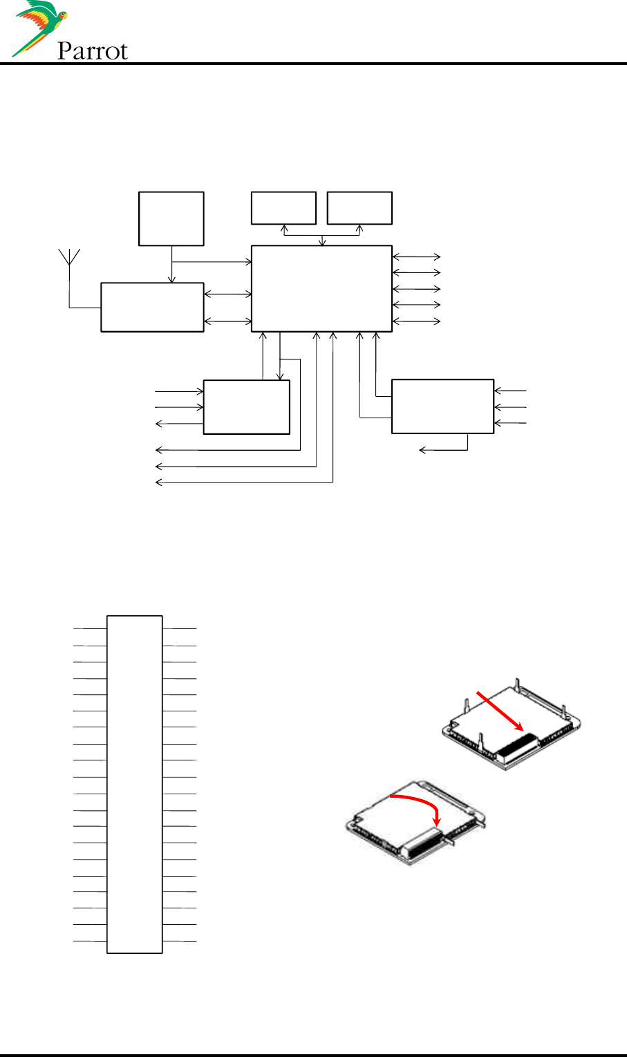
3 Electrical specifications
3.1 Hardware architecture
Parrot
P5+
SDRAM
CAN
2*USB 2 Full speed Host
2*UART
I²C
I²S in/out
PCM in/out
Analog line in
2*Analog output
2*GPIO
FLASH26MHz
Osc.
RF Baseband
2.0+EDR
UART
PCM
CODEC
I²S in
I²S out
Supply
& reset
I²S out
2*microphone input
Reset
Boots
nReset
power
Boots
Various
Voltages
(internal)
Internal
or
external
antenna
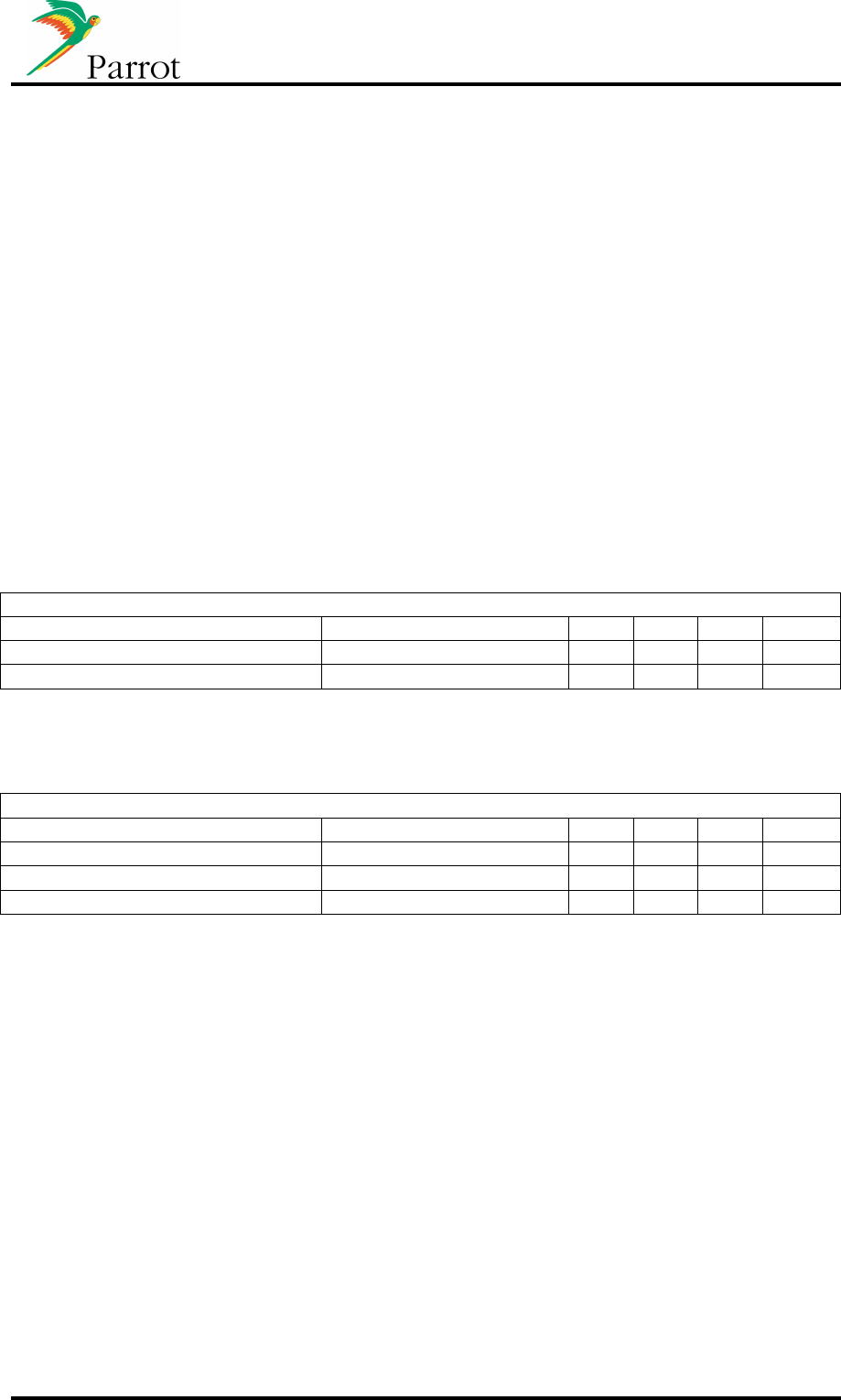
3.2 Pinout
3.2.1 40 pins diagram
I2C_CLK
I2C_DA
I/O2
USB1_D-
USB1_D+
NRESET
VSS
U1_OUT
U1_IN
U0_OUT
U0_IN
I2S_OUT2
I2S_IN
I2S_CLK
Vcc
SPK1P
HP_COM
MIC2P
MIC2N
Rin
CAN_Tx
CAN_Rx
I/O1
USB0_D-
USB0_D+
Boots
Vcc
PCM_OUT
PCM_IN
PCM_SYNC
PCM_CLK
I2S_OUT1
I2S_SYNC
I2S_MCLK
Vss
SPK2P
MIC_PWR
MIC1P
MiC2N
Lin
1
3
5
7
9
11
13
15
17
19
21
23
25
27
29
31
33
35
37
39
2
4
6
8
10
12
14
16
18
20
22
24
26
28
30
32
34
36
38
40
Pin 1
Pin 1
*
*
: BT2.1 + EDR will be available in 09Q3

DATASHEET Confidential Information 9/49
3.2.2 Pinout table
Pin
Function
Type
Description
01
CAN_TX
O
CAN interface
02
I2C_CLK
O
I²C clock
03
CAN_RX
I
CAN interface
04
I2C_DA
I/O
I²C data
05
I/O_
1
I/O
General purpose IO
06
I/O_2
I/O
General purpose IO
07
USB0_D
-
I/O
USB interface data
-
08
USB1_D
-
I/O
USB interface data
-
09
USB0_D+
I/O
USB interface data +
10
USB1_D+
I/O
USB interface data +
11
Boots
I
Command for software update
12
Nreset
I
Reset
13
Vcc
Power
Power
14
Vss
Power
Ground
15
PCM_OUT
O
PCM data out
16
U1_OUT
O
UART
out (debug)
17
PCM_IN
I
PCM data in
18
U1_IN
I
UART in (debug)
19
PCM_SYNC
I/O
PCM synchronization
20
U0_OUT
O
UART out
21
PCM_CLK
I/O
PCM clock
22
U0_IN
I
UART in
23
I2S_OUT1
O
I²S data out
24
I2S_OUT2
O
I²S data out
25
I2S_SYNC
I/O
I²S synchronization
26
I2S_IN
I
I²S data in
27
I2S_MCLK
I/O
I²S master clock
28
I2S_CLK
I/O
I²S clock
29
Vss
Power
Ground
30
Vcc
Power
Power
31
SPK2P
O
Analog audio out
put (left)
32
SPK1P
O
Analog audio output (right)
33
MIC_PWR
O
Microphone power supply
34
HP_COM
I
Headphone ground common feedback input
35
MIC1P
I
Analog microphone differential input +
36
MIC2P
I
Analog microphone differential input +
37
MIC1N
I
A
nalog microphone differential input
-
38
MIC2N
I
Analog microphone differential input
-
39
Lin
I
Analog audio line in (left)
40
Rin
I
Analog audio line in (right)

DATASHEET Confidential Information 10/49
3.2.3 Unconnected pins advice
Pin
Function
Type
Comment
01
CAN_TX
O
02
I2C_CLK
O
Left ope
n
03
CAN_RX
I
04
I2C_DA
I/O
Left open
05
I/O_1
I/O
To be configured as
input
and
connected to
Vss
06
I/O_2
I/O
To be configured as input and connected to
Vss
07
USB0_D
-
I/O
Left open
08
USB1_D
-
I/O
Left open
09
USB0_D+
I/O
Left open
10
USB1_D+
I/O
Left open
11
BOOTS
I
Left open
15
PCM_OUT
O
16
U1_OUT
O
Left open
17
PCM_IN
I
18
U1_IN
I
Pull Up 22KOmhs
19
PCM_SYNC
I/O
20
U0_OUT
O
Left open
21
PCM_CLK
I/O
22
U0_IN
I
Left open
23
I2S_OUT1
O
Left open
24
I2S_OUT2
O
Left open
25
I2S_SYNC
I/O
Left open
26
I2S_IN
I
Pull Down 47KOmhs
27
I2S_MCLK
I/O
Left open
28
I2S_CLK
I/O
Left open
31
SPK2P
O
32
SPK1P
O
33
MIC_PWR
O
Left open
34
HP_COM
I
35
MIC1P
I
Connect directly to ground
36
MIC2P
I
Connect directly to ground
37
MIC1N
I
Conn
ect directly to ground
38
MIC2N
I
Connect directly to ground
39
Lin
I
Connect to ground through a capacitor (1nF)
40
Rin
I
Connect to ground through a capacitor (1nF)
DATASHEET Confidential Information 11/49
3.3 Maximum ratings
Operating temperature range ........................................................................... -40°C to +85°C
Storage temperature range ............................................................................ -40°C to +125°C
Voltage on Vcc with respect to Vss.................................................................... -0.3V to +3.7V
ESD sensitivity according ES-XW7T-1A278-AC ............................................................... ±4kV
3.4 Power consumption
(T°=-40°C to +85°C)
Stop mode ..................................................................................................................... <20µA
Idle mode (waiting for commands) .............................................................................. <150mA
Hands free and audio streaming mode ....................................................................... <300mA
3.5 Electrical specifications
3.5.1 Power pins
Conditions unless noted, otherwise : Tamb.=25°C
Parameter
Conditions
Min.
Typ.
Max.
Unit
Normal supply 3.2 - 3.6 V
3.5.2 Reset pin
Conditions unless noted, otherwise : T=-40°C to +85 °C; Vcc=3V2 to 3V6
Paramet
er
Conditions
Min.
Typ.
Max.
Unit
Reset time 50 - - µs
Active reset voltage level - - 0.4 V
Non active reset voltage level 2.5 - - V

DATASHEET Confidential Information 12/49
3.5.3 IO pins
Electrical parameters of the GPIO pins (5 and 6)
Conditions unless noted, otherwise : T=-40°C to +85 °C; Vcc=3V2 to 3V6
Parameter
Conditions
Min.
Typ.
Max.
Unit
Input voltage 0 - Vcc V
Output voltage 0 - Vcc V
High level input voltage (
Vih min
) 0.7*
Vcc
- - V
Low level input voltage (
Vil max
) - - 0.2*Vcc V
Low level input current Vi=0V;
pull up
- - 100 µA
High level input current Vi=Vcc;
pull down
- - 92 µA
Hysteresis voltage 0.5 0.62 V
High level output voltage (
Voh min
)
Iout= n mA Vcc-0.4 3.3 - V
Low level output voltage (
Vol max
) Iout= n mA - - 0.4 V
Level output current Vout= n V - - 2 mA
3.5.4 CAN
Conditions unless noted, otherwise : Tamb.=25°C; Vc c=3V3
Parameter
Conditions
Min.
Typ.
Max.
Unit
Input high level voltage (Vih min) 0.7*
Vcc
- Vcc V
Input low level voltage (Vil max) - - 0.2*Vcc V
Output high level voltage (Voh
min) Vcc-0.4 - - V
Output low level voltage (Vol
max) - - 0.4 V
DATASHEET Confidential Information 13/49
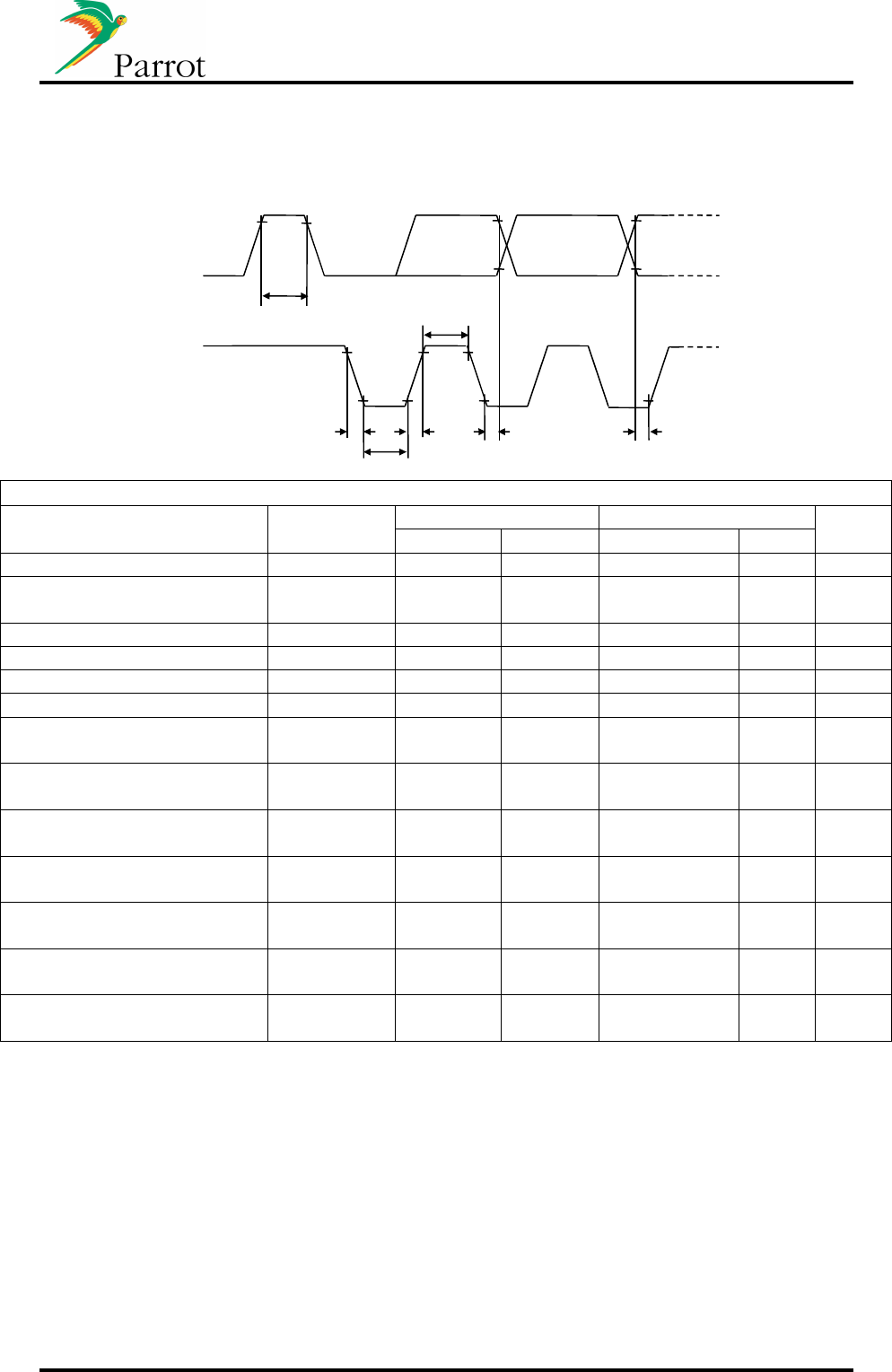
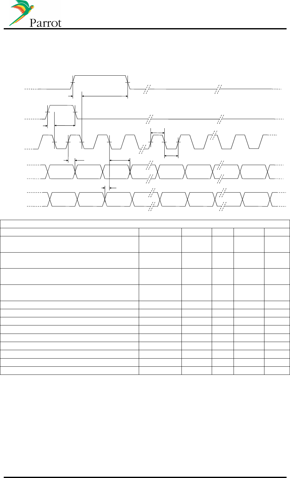
3.5.5 I²C
Timing parameters of the I²C bus (pins 2 and 4)
Tr
Tf
Tbus
SCL
SDA
Tclk(l)
Tdat(h)
Tclk(h)
Tdat(s)
Conditions unless noted, otherwise : Tamb.=25°C; Vc c=3V3
Parameter
Conditions
I²C 100kHz I²C 400kHz
Unit
Min.
Max.
Min.
Max.
SCL clock frequency 0 100 0 400 kHz
Bus free between start and
stop (Tbus) 6 - 1.5 - µs
Low period of SCL (Tclk(l)) 6 - 1.5 - µs
High period of SCL (Tclk(h)) 4.0 - 0.6 - µs
Data hold time (Tdat(h)) 50 50 ns
Data setup time (Tdat(s)) 50 - 50 - ns
Rise time of both SDA &
SCL (Tr) - 50 - 50 ns
Fall time of both SDA &
SCL (Tf) - 50 - 50 ns
Max. capacity load for each
bus line - 400 - 400 pF
Input high level voltage (Vih
min) 0.7*
Vcc
- 0.7*
Vcc
- V
Input low level voltage (Vil
max) - 0.2*Vcc - 0.66 V
Output high level voltage
(Voh min) Vcc-0.4 - Vcc-0.4 - V
Output low level voltage
(Vol max) - 0.4 - 0.4 V

DATASHEET Confidential Information 14/49
(1)
3.5.6 USB
Conditions unless noted, otherwise : Tamb.=25°C; Vc c=3V3; Cload=50pF
Parameter
Conditions
Min.
Typ.
Max.
Unit
Differential input sensitivity |(D+)-(D-)| TBD - - V
Differential common mode voltage
range Include differential
input sensitivity TBD - TBD V
Single ended receiver switching
threshold voltage TBD - TBD V
Low level output voltage for low and
full speed Rload=1.5kΩ to 3V3 - - TBD V
High level output voltage for low and
full speed Rload=1.5kΩ to Vss TBD - TBD V
Transceiver capacitance Pin to Vss - - TBD pF
Rise time 10% to 90% 4 - 20 ns
Fall time 10% to 90% 4 - 20 ns
Output signal crossover voltage 1.3 - 2 V
Input high level voltage (Vih min) TBD - - V
Input low level voltage (Vil max) - - TBD V
Output high level voltage (Voh min) TBD - - V
Output low level voltage (Vol max) - - TBD V
3.5.7 UART0/UART1
Conditions unless noted, otherwise : Tamb.=25°C; Vc c=3V3
Paramete
r
Conditions
Min.
Typ.
Max.
Unit
Input high level voltage (Vih min) 0.7*Vcc
- - V
Input low level voltage (Vil max) - - 0.2*Vcc
V
Output high level voltage (Voh min) 0.4*Vcc
- - V
Output low level voltage (Vol max) - - 0.4 V
Rise time Cload=10pf - - 170 ns
Fall time Cload=10pf - - 160 ns
Baud rate - - 650 kbps
Emission Baud rate precision - 0.25 - %
Reception Baud rate tolerance - 4 - %
DATASHEET Confidential Information 15/49
3.5.8 PCM
Timing parameters of PCM interface (pins 15, 17, 19 & 21)
Clock
Data IN
Tdat.in(s)
MSB LSB MSB LSB
MSB LSB MSB LSB
Tdat.in(h)Tdat.out(v)
Tfs.oki(h)
Tfs.oki(s)
Tfs.ti(h)
Tfs.ti(s)
Tclk(h)
Tclk(l)
Data OUT
OKI frame sync
TI frame sync
Conditions unless noted, otherwise : Tamb.=25°C; Vc c=3V3
Parameter
Conditions
Min.
Typ.
Max.
Unit
Frame sync TI to clock falling setup time
(Tfs.ti(s)) 10 - - ns
Frame sync TI to clock falling hold time
(Tfs.ti(h)) 10 - - ns
Frame sync Oki to clock falling setup time
(Tfs.oki(s)) 10 - - ns
Frame sync Oki to clock falling hold time
(Tfs.oki(h)) 10 - - ns
PCM clock high time (Tclk(h)) 100 - - ns
PCM clock low time (Tclk(l)) 100 - - ns
PCM data in hold time (Tdat.in(h)) 10 - - ns
PCM data in setup time (Tdat.in(s)) 10 - - ns
PCM data out volid time (Tdat.out(v)) - - 25 ns
Input high level voltage (Vih min) 0.7*Vcc
- - V
Input low level voltage (Vil max) - - 0.2*Vcc
V
Output high level voltage (Voh min) 0.4*Vcc
- - V
Output low level voltage (Vol max) - - 0.4 V
DATASHEET Confidential Information 16/49
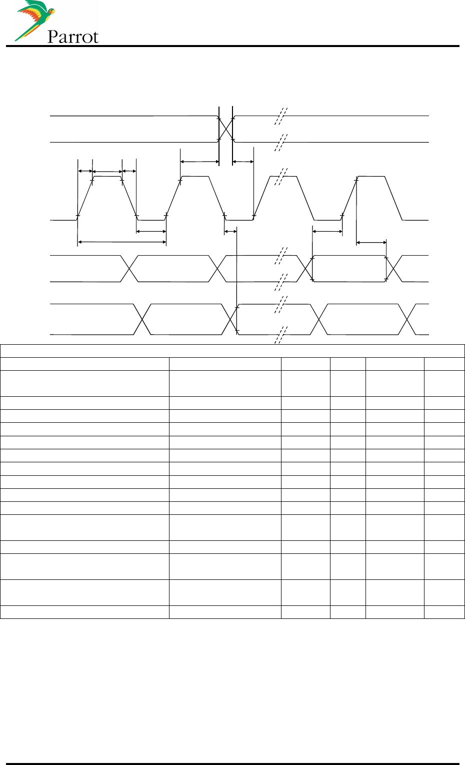
3.5.9 I²S
Timing and electrical parameters of I²S interface (Pins 23 to 26)
Tcy
Tclk(l)
Tr Tf
Tclk(h)
LSB MSB
Tdat(s)
Tdat(h)
Tsync(h) Tsync(s)
Tdat(d)
Clock
Sync
Data in
Data out
Conditions unless noted, otherwise : Tamb.=25°C; Vc c=3V3
Parameter
Conditions
Min.
Typ.
Max.
Unit
Bitclock cycle time (Tcy) 325
(48kHz)
- 354
(44.1kHz)
ns
Bitclock Rise time (Tr) - - 10 ns
Bitclock Fall time (Tf) - - 10 ns
Bitclock time high (Tckl(h)) 150 - - ns
Bitclock time low (Tckl(l)) 150 - - ns
Data setup time (Tdat(s)) 10 - - ns
Data hold time (Tdat(h)) 10 - - ns
Data delay time (Tdat(d)) - - 100 ns
Sync setup time (Tsync(s)) 10 - - ns
Sync hold time (Tsync(h)) 10 - - ns
High level input voltage (Vih
min) 0.7*Vcc
- - V
Low level input voltage (Vil max)
- - 0.2*Vcc V
High level output voltage (Voh
min) 0.4*Vcc
- - V
Low level output voltage (Vol
max) - - 0.4 V
Drive load capability - 2 mA

DATASHEET Confidential Information 17/49
3.5.10 Analog out
Electrical parameters of SPK1P and SPK2P pins (29 and 30).
Conditions unless noted, otherwise : Tamb.=25°C; Vc c=3V3
Parameter
Conditions
Min.
Typ.
Max.
Unit
Average DC output voltage - 1.5 - V
Bandwidth -3dB 3.8 - 21.1K
Hz
Load resistor 16 - - Ω
Full scale output Rload=10K, Gain=0dB 0,9 V
rm
s
THD+N Rload AC=20kΩ, f=1kHz,
OdB - - 80 dB
SNR @1kHz, A-Weighted - 65 - dBA
3.5.11 Line in
Electrical parameters of the line-in pins (39 and 40).
Conditions unless noted, otherwise : Tamb.=25°C; Vc c=3V3
Parameter
Conditions
Min.
Typ.
Max.
Unit
Full scale input voltage THD<0.5% - 0.7 V
rm
s
Input resistance Gain=0dB 46 kΩ
THD+N 1kHz, 1.3Vrms,
BW=20kHz - 85 dB
SNR 1kHz, Bw=20kHz,
0dBref.=1.3Vrms, A-
weighted
75 - dBA
Audio input frequency response -3dB roll off 12 - 21k Hz
3.5.12 Microphone input
Conditions unless noted, otherwise : Tamb.=25°C; Vc c=3V3
Parameter
Conditions
Min.
Typ.
Max.
Unit
Maximum input impedance data - - TBD Ω
DC input voltage (Pin MIC_PWR) - TBD - V
Max. AC input voltage @ THD = 0.05% TBD TBD TBD mV
rm
s
SNR @1kHz, A-weighted,
G=0dB, Vin=800mVrms - 80 - dBA
THD+N @1kHz, Vin=300mVrms - 90 - dB
Bandwidth -3dB, G=0dB,
Vin=800mVrms 7 - 21k Hz

DATASHEET Confidential Information 18/49
3.5.13 Bluetooth radio link
Conditions unless noted, otherwise : Tamb.=25°C; Vc c=3V3
Parameter
Conditions
Min.
Typ.
Max.
Unit
Antenna impedance Module with connector only - 50 - Ω
DATASHEET Confidential Information 19/49
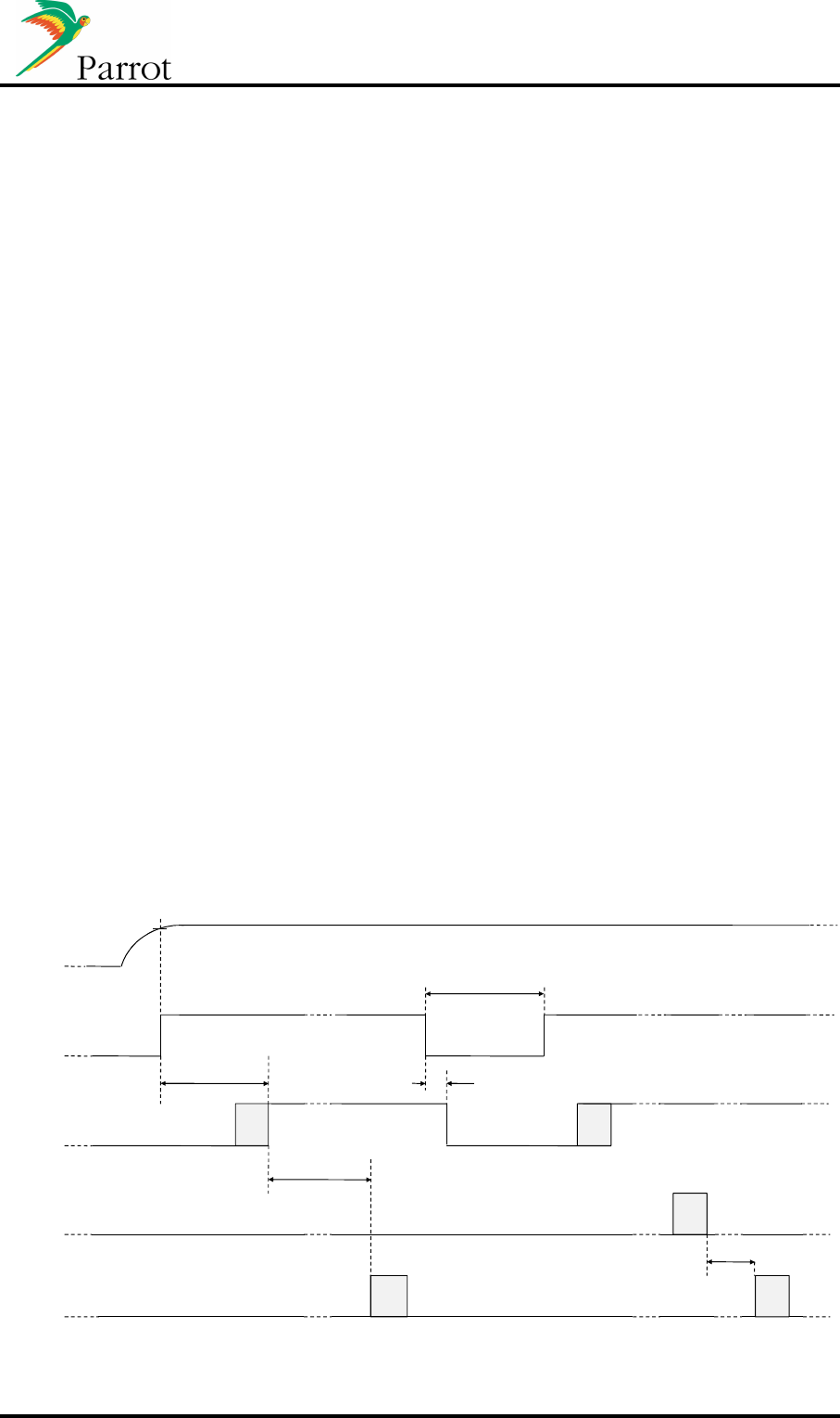
3.6 Reset and supply sequence diagram
3.6.1 Switching ON
•
The signal “NRESET” on the host interface is forced to a logical zero value by host
until the supply voltage reached its nominal value.
During this phase no component on the module is supplied.
•
The host switches its signal “NRESET” to a logical one value allowing the module to
turn on its supply.
•
After 70 ms, the supply gets stabilized and then triggers the start of the ASIC
•
100ms is necessary for the ASIC to start and give execution to the embedded
software that will turn the module into a permanent “active mode”
3.6.2 Switching OFF
•
The host sends the "sleep” AT command
•
The ASIC disconnects any BT link
•
The ASIC sends the "sleep acknowledge" AT command allowing the host to switch
the reset to a zero logical value.
•
If the host activate the “NRESET” to zero for at least 5 us but no more than 4ms the
module will be reset.
•
The signal “NRESET” on the host interface is forced to a logical zero value by host
until the supply voltage reached its nominal value.
Note: Switching off is also possible during “active mode” by turning reset to “zero” during
500ms. This unexpected reset is not recommended because some BT devices may
abnormally behave if the BT link is not properly disconnected.
3.6.3 Diagram
NRST
(Internal P5+ reset)
UART0 out
Delay : 70ms max.
AT*POFF
UART0 in
NRESET
Vcc
Tmin to reset = 50µs.
Delay 10s max.
Delay 3s max.
Delay : 50µs
3v2
DATASHEET Confidential Information 20/49
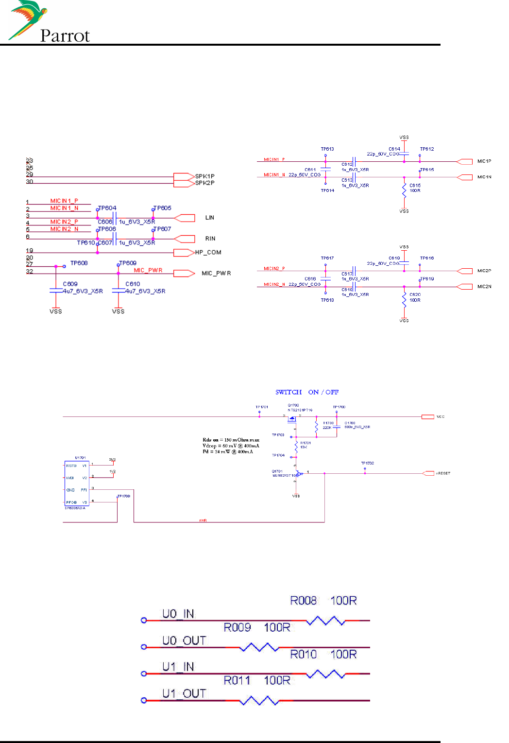
3.7 Internal Components schematics
3.7.1 Audio I/O
3.7.2 Boot/reset and Power supply
3.7.3 Serial Link
DATASHEET Confidential Information 21/49
3.8 Integration recommendations
3.8.1 Analog out
3.8.2 Analog in
C78
2n7_50V_COG
C79
2n7_50V_COG
J3
Jack_3_5mm
1
2
3
VSS
CK5050New audio output
VSSVSS
R133
470R R134
470R
SPK1P
SPK2P
C81
1n8_50V_COG
C82
10u_6V3_X5R
C83
10u_6V3_X5R
LIN
RIN
R135
100R R136
100R
J9
Jack_3_5mm
1
2
3
R137
100K
VSS
R138
100K
Line in
VSS
VSS VSS
VSS
C80
1n8_50V_COG
DATASHEET Confidential Information 22/49
3.8.3 Microphone input
R99 0R
3V3_CK5050New
C51
100n_25V_X5R
R168
47K
VSS
MIC_PWRMIC_PWR
R167
680R
VSS
VSS
C50
47u_6V3_X5R
VSS
MIC1N
MIC1P
VSS
NU_R94
100R
C101
220p_50V_COG
NU_R100
>100R
C16
4u7_10V_X5R
Note: Microphone input routing.
• The microphone can use internal or external power supply. Take care to have the same
ground reference between your supply and the pull down resistor on MICxN.
• For an external power supply, you have to put a resistor more than 100R. If you use the
internal power supply, you needn’t to use an external resistor.
3.8.4 I2S
Note: I2S routing
• Parrot advises to route
I2S_MCLK in internal layout with ground around.
• The filters have to be put near of Parrot connector.
VSS
VSS
VSS
C73
10p_50V_COG
I2S_MCLK
C74
10p_50V_COG
C75
10p_50V_COG
C76
10p_50V_COG
I2S_OUT2
I2S_CLK
R128 39R
R129 39R
R130 39R
I2S_OUT1
R131 39R
C77
10p_50V_COG
R132 39R
VSS
I2S_SYNC
VSS

DATASHEET Confidential Information 23/49
3.8.5 USB
Note: USB Routing:
• Maintain parallelism between USB differential signals with the trace spacing needed to achieve 90
ohms differential impedance i.e the separation between the two traces; D+, D-, shall be larger than
their distances towards the USB signal reference plane: 90 Ohms differential = 2 times 45 Ohms to
ground in series.
• Avoid 90° turns , use two 45° turns or an arc instead.
• Do not route USB traces under crystals, oscillators.
• Route high-speed USB signals using a minimum number of vias and corners (avoid changing layers with
high-speed traces as much as practical.)
• Stubs on high speed USB signals e.g.towards the pull-down resistors, should be avoided
• Verify with an impedance calculator or TDR that the trace spacing and the trace width used on the
specific board stack up to 90 ohms differential impedance. With low or minimal coupling between the
two traces; D+, D-, the characteristic impedance towards the USB signal reference is dominant and
shall be equal to 45 Ohm single ended.
• HIGH SPEED USB signal pair traces should be trace length matched. The maximum trace length
mismatch between HS USB signal pairs should be no greater than 200 mils.
• Ensure D+ and D- traces have grounded solid guard traces aside and a solid USB signal reference plane
underneath them from the USB connector up to the USB transceiver device.
USB1_5V
VSS
USB1_D-
USB1_D+
5V
C7
1u_10V_X5R
R143
0R
J11
Mini_USB_5points
1
1
2
2
3
3
4
4
5
5
Blindage1
f ix1
Blindage2
f ix2
Blindage3
f ix3
Blindage4
f ix4
R210R R220R
VSS
DATASHEET Confidential Information 24/49
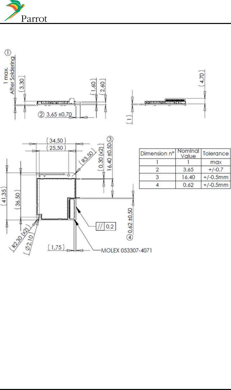
4 Mechanical specifications
4.1 Horizontal module with internal antenna
DATASHEET Confidential Information 25/49
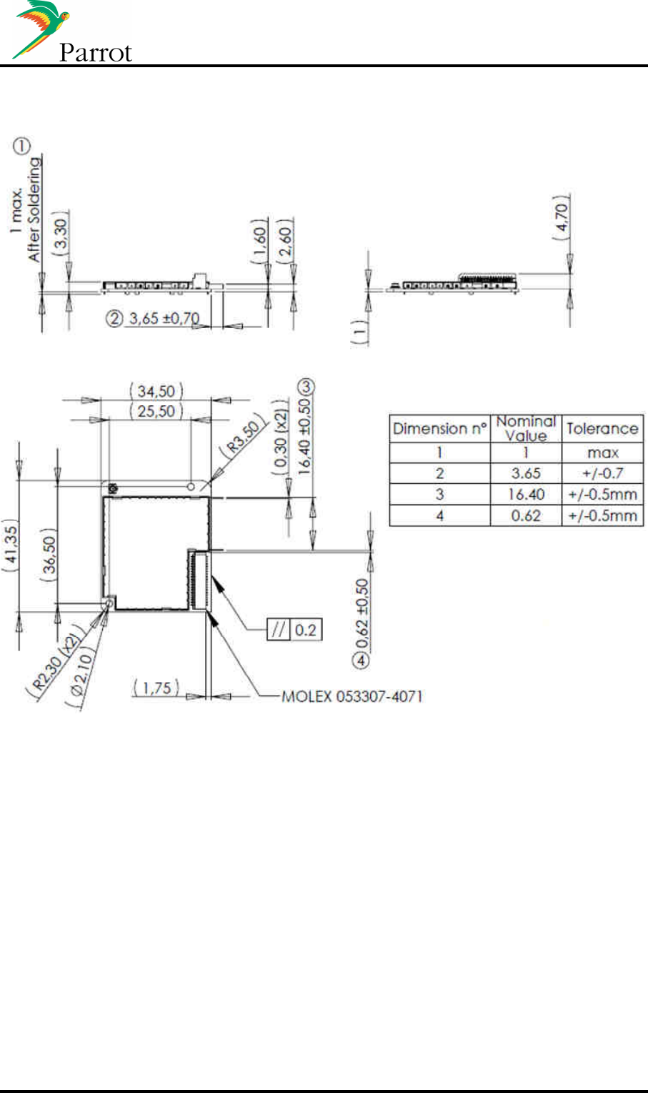
4.2 Horizontal module with external antenna
DATASHEET Confidential Information 26/49
4.3 Vertical module with internal antenna
DATASHEET Confidential Information 27/49
4.4 Vertical module with external antenna
DATASHEET Confidential Information 28/49
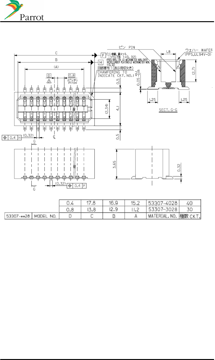
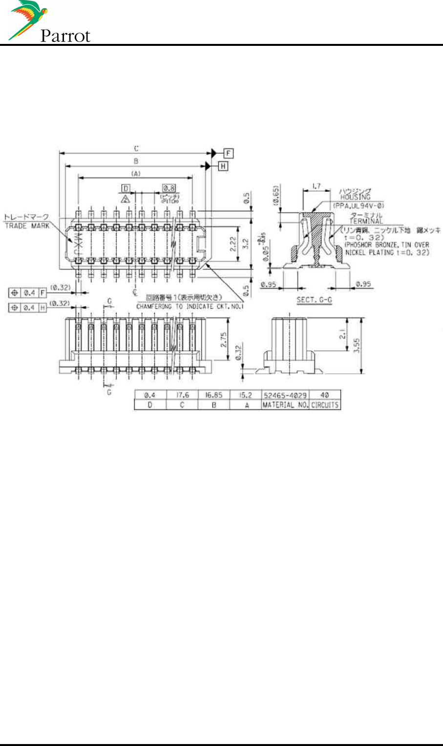
4.5 Connector of horizontal version
DATASHEET Confidential Information 29/49
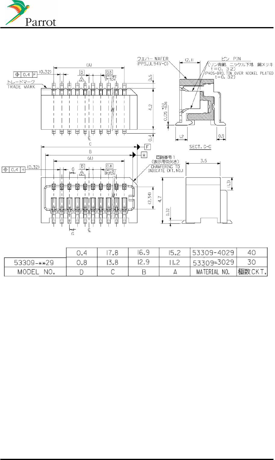
4.6 Connector of vertical version
DATASHEET Confidential Information 30/49
4.7 PCB footprint for horizontal module
4.8 PCB footprint for vertical module
4.9 Connectors specifications
DATASHEET Confidential Information 31/49
5 Available tools
5.1 Workbench
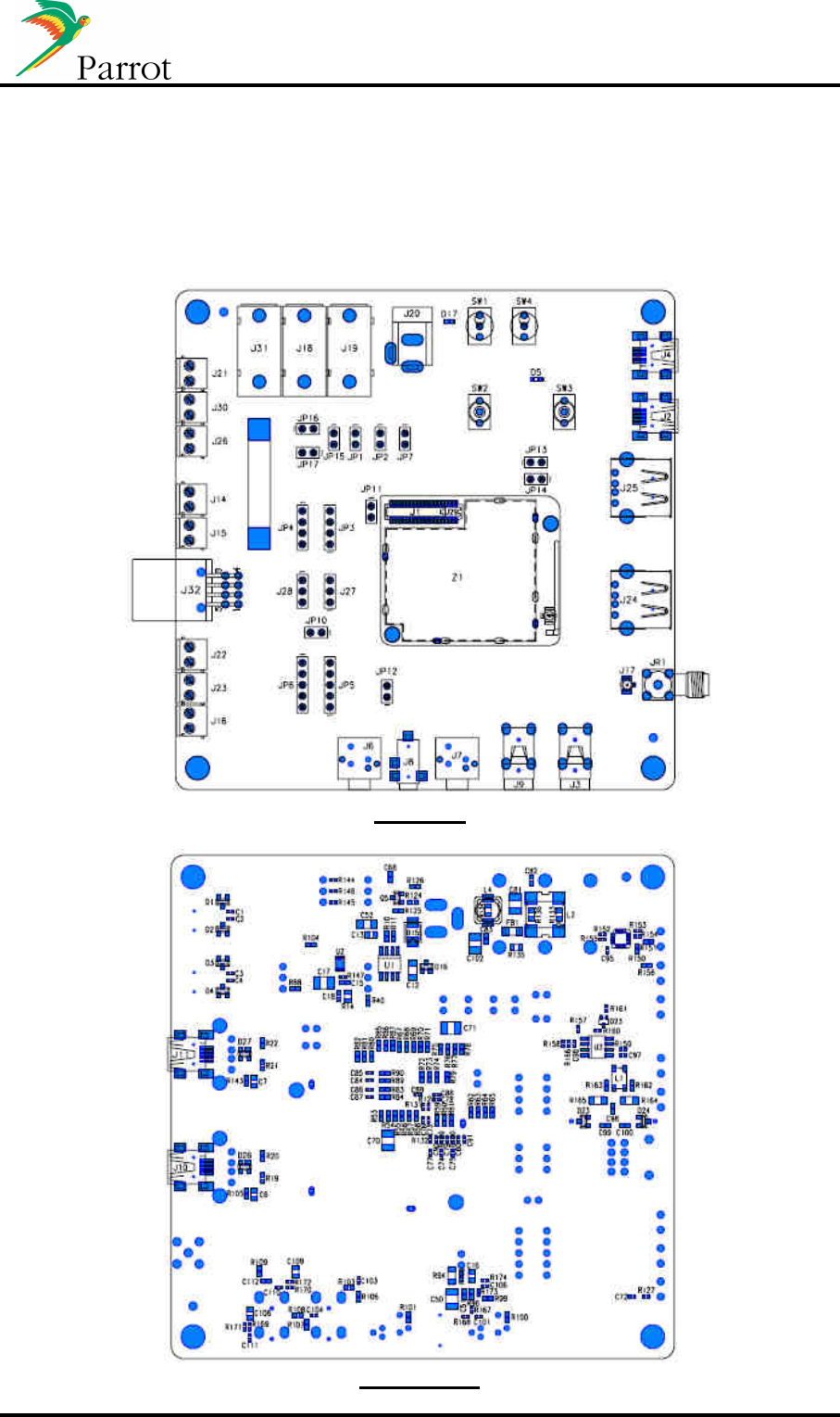
5.1.1 Diagram
TOP view
Bottom view
DATASHEET Confidential Information 32/49
5.1.2 Schematics
The work bench schematic will be provided on demand
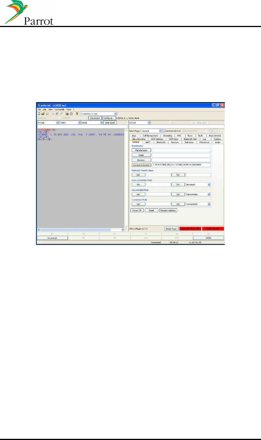
5.2 Wxserial
Wxserial is a windows based software that gives the possibility to send and read the AT commands
used by the CK5050New.

DATASHEET Confidential Information 33/49
6 Approval / Certifications
6.1 CE Declaration
We, Parrot SA 174 quai de Jemmapes 75010 Paris France, declare under our responsibility that our
product (Parrot CK5050NEW) is in conformity with the Radio and Telecommunication Equipment
directive 1999/5/EC R&TTE according to the essentials requirements and respect the standard listed
below :
3.1-a) Electrical Safety EN60950-1:2001/A11:2004
EMF EN50371 (06/2002)
3.1-b) EMC EN301 489-1 V1.6.1
3.2 Radio EN300 328 V1.7.1
Paris, July 30th , 2009
Qualification Manager
Arezki Guerrab

DATASHEET Confidential Information 34/49
6.2 FCC and IC requirements for module application
FCC ID: RKXCK5050NEW
IC : 5119A-CK5050NEW
In accordance with FCC Part 15, the CK5050+ is listed as a Modular Transmitter device.
USA – User information
This intends to inform how to specify the FCC ID of our module “ CK5050NEW ” on the product.
Based on the Public Notice from FCC, the host device should have a label which indicates that it
contains our module. The label should use wording such as: “Contains FCC ID: RKXCK5050NEW”
Any similar wording that expresses the same meaning may be used.
The label of the host device should also include the below FCC Statement. When it is not possible,
this information should be included in the User Manual of the host device.
“This device complies with part 15 of the FCC rules. Operation is subject to the following two
conditions.
(1) This device may not cause harmful interference
(2) this device must accept any interference received, including interference that may cause
undesired operation.
Caution: Changes or modifications not expressly approved by the party responsible for compliance
could void the user’s authority to operate the equipment.
Canada – User information
This intends to inform how to specify the IC ID of our module “ CK5050NEW ” on the product.
According to Canadian standards “RSS 210” and “RSS Gen” , the host device should have a label
which indicates that it contains our module. The label should use wording such as: “Contains IC ID:
519A-CK5050NEW
Any similar wording that expresses the same meaning may be used.
The label of the host device should also include the below IC Statement.
When it is not possible, this information should be included in the User Manual of the host device.
“Operation is subject to the following two conditions:
(1) this device may not cause interference,and
(2) this device must accept any interference, including interference that may cause undesired
operation of the device.”
6.3 RoHS declaration

DATASHEET Confidential Information 35/49
ANNEXE
A. Bluetooth HFP & A2DP/AVRCP use cases overview:
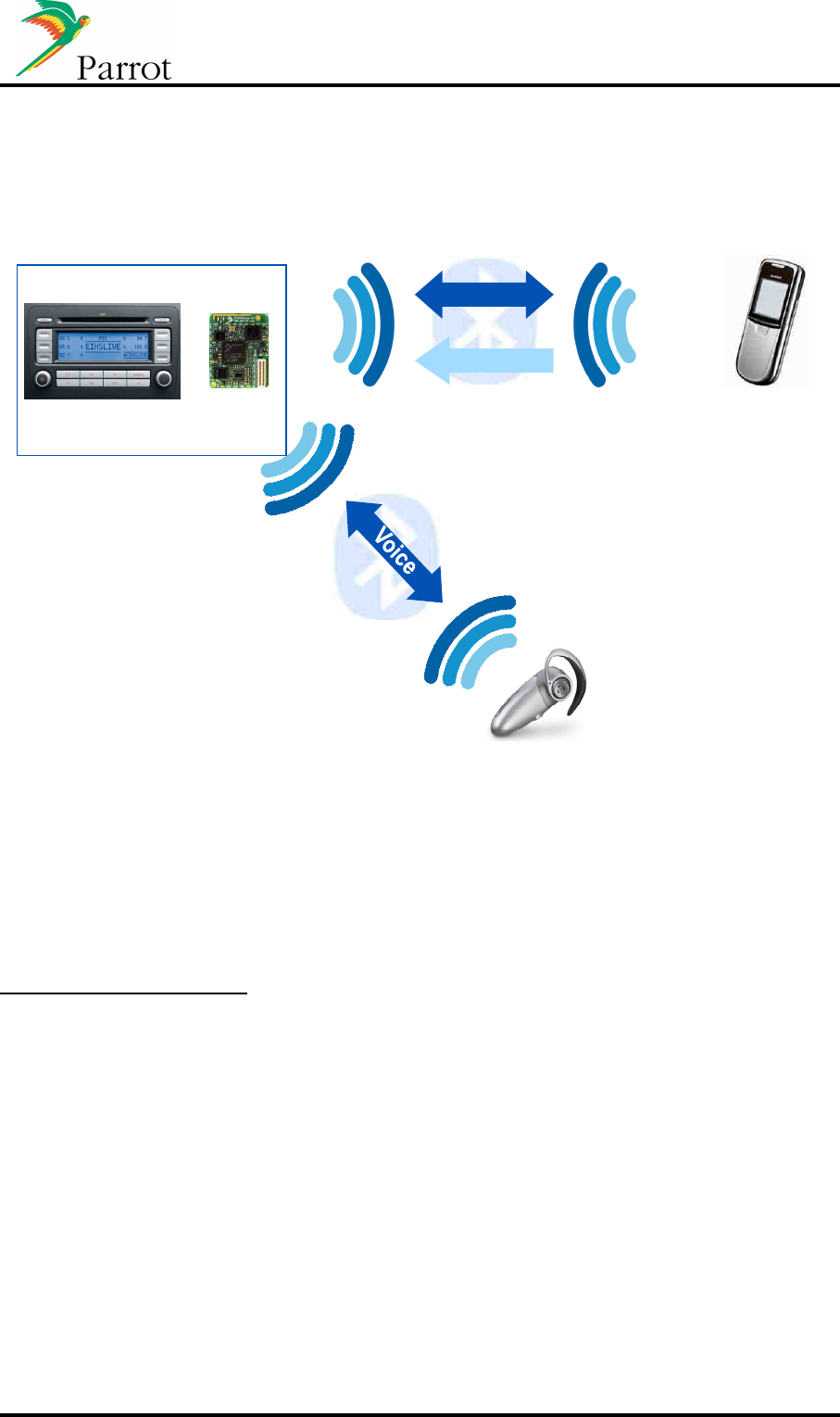
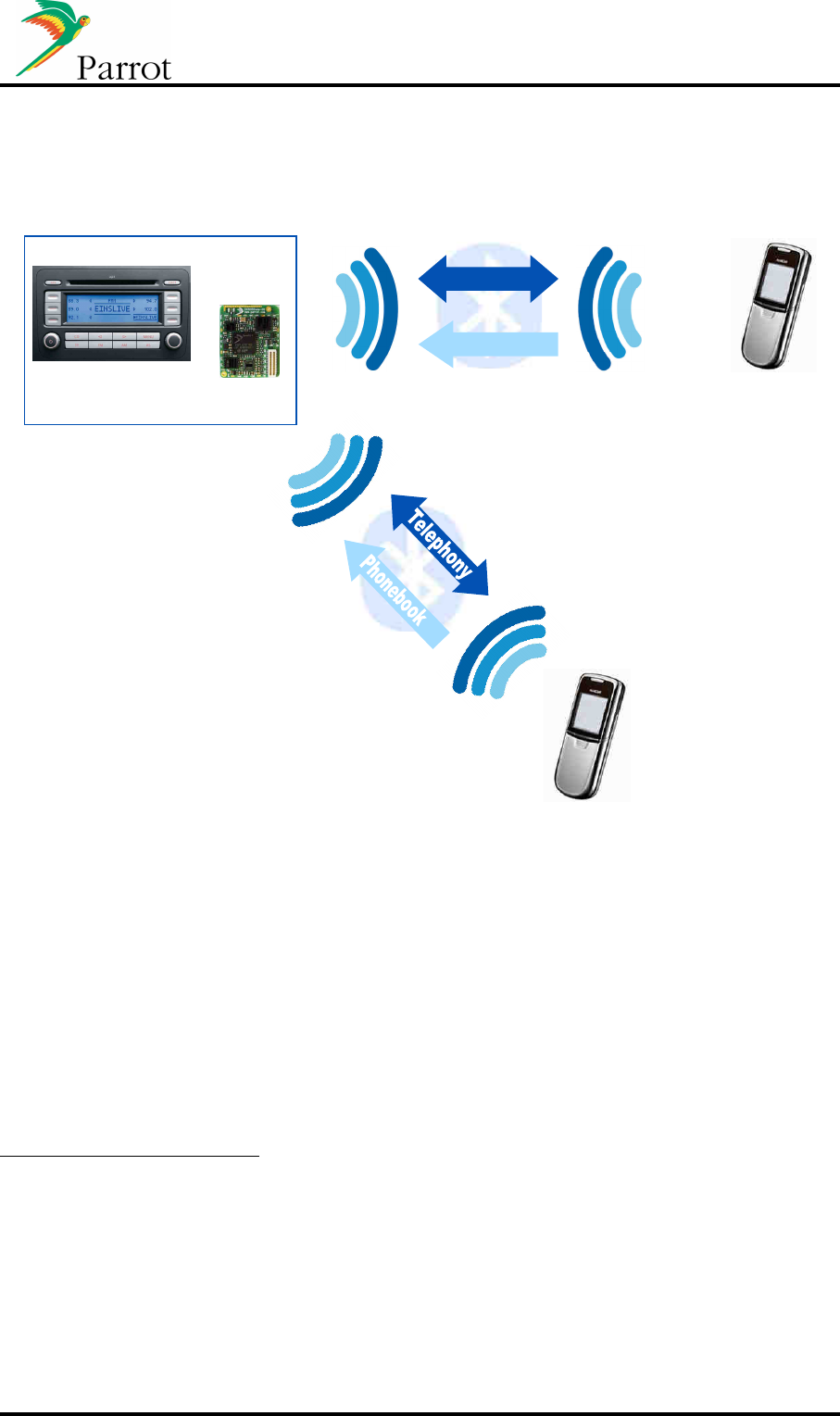
a. Head Unit paired with Mobile phone
Handsfree telephony & Phonebook Synchronization
Hands Free Audio Gateway
Hands Free Device
Mobile Phone
Audio unit
Hands Free Telephony
Telephony
Phonebook
Phonebook synchro
CK5050New & Host
Connections Strategy
If the Host does not store the last synchronized phonebook, it is always available for the Host
at Module start up. Right after HFP connection (which is initiated to the last connected
device), it is possible to place an outgoing call if requested. Once HFP initialization has
finished (end of SLC/Extended SLC), the Module starts the best phonebook synchronization
method available on the phone. The Module alerts the Host that the updated phonebook with
new entries is available, and ready to be displayed on the HMI.
If an incoming/outgoing call occurs during the phonebook synchronization process,
depending on the method of phonebook synchronization which is used, the process is
paused. Once the call is finished, the phonebook synchronization restarts from where it has
been stopped, and the call history is updated. This is transparent for the end user.
Calls Management
For incoming calls, the Caller ID (received from phone via CLIP or CLCC) is sent to the Host
to be displayed on the HMI.
HFP indicators such as signal level, battery level and network provider are forwarded to the
Host to be displayed on the HMI. CIND/CIEV indicators or GSM AT Commands are used for
this purpose.
Service Continuity
This feature handles the audio management of a call when the module is powered on/off:
- When the module is powered on, the module automatically connects HFP to the
phone and establishes the communication ((e)SCO connection) through the speakers
during the SLC.
- When the module is powered off, the module transfers the audio to the phone
((e)SCO disconnection) and disconnects the Bluetooth link.
This process ensures the Host to be immediately ready to start Handsfree usage.

DATASHEET Confidential Information 36/49
Three way calling / multiple calls management
Once a call is established, if a second incoming call occurs, here is how the Host should
handle the HMI:
- Green button: takes the second incoming call as active, and put the first one on hold.
Press green button again to switch between the two calls.
- Red button: hangs up the active call and takes the second one as active.
Full 3-way calling management (and multiparty calls) is optimized with phones supporting
HFP1.5. Parrot supports up to 7 calls at the same time for conference calls purpose.
With phones supporting HFP1.0 only, there are gaps in the specification such as:
- When the user manages the calls from the phone interface, the phone does not
always notify the Module.
- When the distant party who is on hold hangs up from its side.
DATASHEET Confidential Information 37/49
b. Head Unit connected to Mobile phone and headset device
SCO link
Audio 8 kHz Mono
Car announcements
(Navigation,etc…)
and Communication privacy
Hands Free Audio Gateway
Hands Free Device
Hand Free Audio Gateway
Mobile Phone
Audio unit
Hands Free Telephony
Pho
nebook synchro
Telephony
Phonebook
CK5050New & Host
SCO forwarding feature (2 SCO)
The module is connected to a Headset and a phone at the same time. When requested by
the user, the Module is able to forward audio from the phone to the Headset. Therefore, the
communication is switched for privacy purpose. Two SCO channels are opened from the
Module.
Description of the behavior:
- Incoming call:
o Pick up from the HMI will pick up the call and establish one (e)SCO with the
phone and one with the Headset.
o Hang up from the HMI will hang up the call and release the 2nd SCO.
- Outgoing call:
o Dialing from the HMI will place the call on the phone, and once the remote
party has picked up, one (e)SCO is established with the phone and one with
the Headset.
o Hang up from the HMI will hang up the call and release the 2nd SCO.
A command is proposed on Parrot Module to handle the establishment of dual SCO,
depending on user need.
DATASHEET Confidential Information 38/49
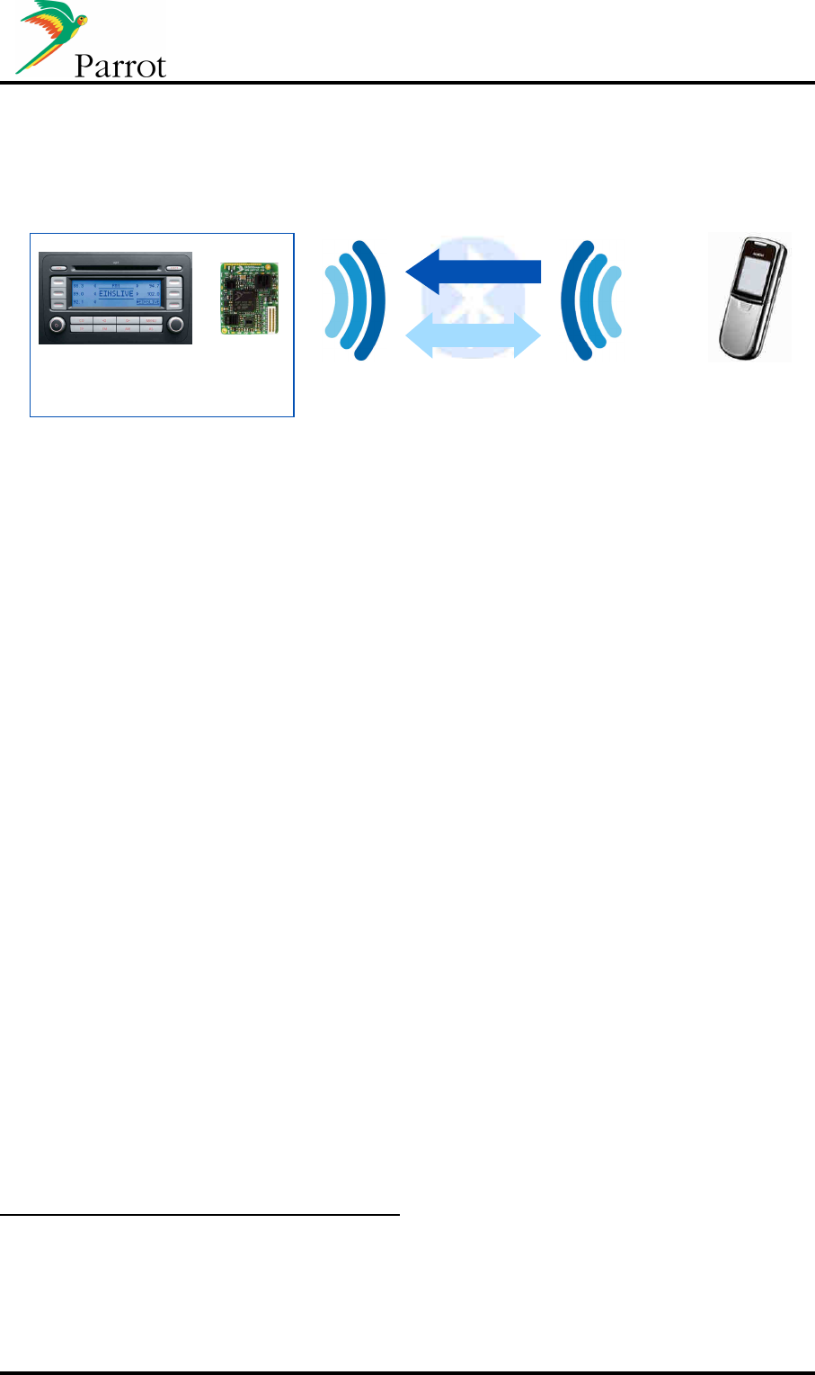
c. Head Unit paired with two Mobile phones
Establish and receiving call possible on two different mobile phones
Hands Free Audio Gateway
Hands Free Device
Mobile Phone
Audio unit
Hands Free Telephony
Telephony
Phonebook
Phonebook synchro
Mobile phone
Hands Free Audio Gateway
CK5050New & Host
Multi HFP Feature
Parrot has developed the “Multi - HFP”, which enables the Module to handle two Handsfree
connections at the same time. This use case is useful for people having two mobile phones,
or when two users are in the car.
The Module is running phonebook synchronization on both phones, and each phone has its
own phonebook available for the Host (phonebooks are not merged).
HFP indicators are available for each phone.
Description of the behaviour:
- First example: two phones (P1 and P2) are connected to HFP service. The host can
start dialing on P1, hang up call then start outgoing call on P2.
- Second example: the phone receives incoming call P1 on Module. After the end of
the first call from P1 the phone P2 can receive incoming call.
The multi HFP does not manage the calls of two phones at the same time.
DATASHEET Confidential Information 39/49
d. Audio Streaming and Handsfree working together
Audio Streaming from phone to Module (remotely controlled by the Module)
A2DP source
A2DP Sink
Mobile Phone or
Music Player
Audio unit
MP3 or SBC (A2DP & AVRC)
44 kHz stereo
Streaming
Control
CK5050New & Host
AVHFP Feature
Most phones now support both HFP and A2DP Source/AVRCP TG. The most difficult case is
to correctly handle the AVHFP Feature (dual use of A2DP/AVRCP and HFP).
As there is no specification release by the Bluetooth SIG explaining how this multi-profile use
case should operate, a whitepaper has been issued by the A/V Working Group
(“Simultaneous Use of HFP, A2DP, And AVRCP Profiles”).
Basically, the Whitepaper states that the phone should handle the streaming restart
management once the call is finished (this is the main concern today):
- Incoming call: the AG should handle the streaming management:
o Pause the streaming on incoming call.
o Send to the HF the indicators (CIEV Call setup)
o Then the HF picks up the call with ATA, communication/SCO is established
o Once finished (from AG or HF), the AG should restart streaming from where it
has been paused.
- Outgoing call from HF (ATD): the AG should also handle this in the same manner.
Nevertheless, most phones do not correctly implement the Whitepaper, and the streaming
does not always restart after the call. Parrot has developed a strategy that automatically
relaunches streaming in this case.
Song information availability
According to the AVRCP version supported by the music player (can be a phone or a
Bluetooth Music player), the Host is updated with the following information in order to update
its HMI.
AVRCP TG 1.0 (Category 1 – Music Players):
- Mandatory commands:
o Play and stop.
- Optional Features:
o Enhanced control: Next, Previous, Pause, FF, FW (most of the
phones/Players supporting AVRCP1.0 support those commands).

DATASHEET Confidential Information 40/49
o There are a lot of other features, but the phone/Bluetooth Music Players do
not implement these extended commands.
AVRCP CT 1.0 (Category 1 – Parrot Module):
- At least one command of the specification should be supported.
- Parrot has decided to implement the full Player Control (events send to the phone):
o Play, Pause, Stop, Next, Previous, Pause, FF, FW
AVRCP TG 1.3 (Category 1 – Music Players):
- Mandatory commands:
o Same perimeter as AVRCP TG 1.0.
- Optional Features:
o If the phone supports the Bluetooth SIG Vendor Unique Feature, only Title of
the Media is mandatory for Metadata. And Playback status and change of
current track shall be supported in this case.
o Other important features for Metadata support are Name of the Artist, Name of
the Album, Genre...
AVRCP CT 1.3 (Category 2 – Parrot Module):
- Mandatory commands:
o Same perimeter as AVRCP CT 1.0.
- Parrot optional features implemented:
o Referring to the specification, all “List of Media Attributes” are supported to be
displayed on the car radio HMI.
According to the AVRCP version supported by the phone, the HMI should be implemented
with information provided by the Module: Player status / Metadata for the current played
song.
As member of AV Working Group, Parrot is involved with the development of those
specifications.
DATASHEET Confidential Information 41/49
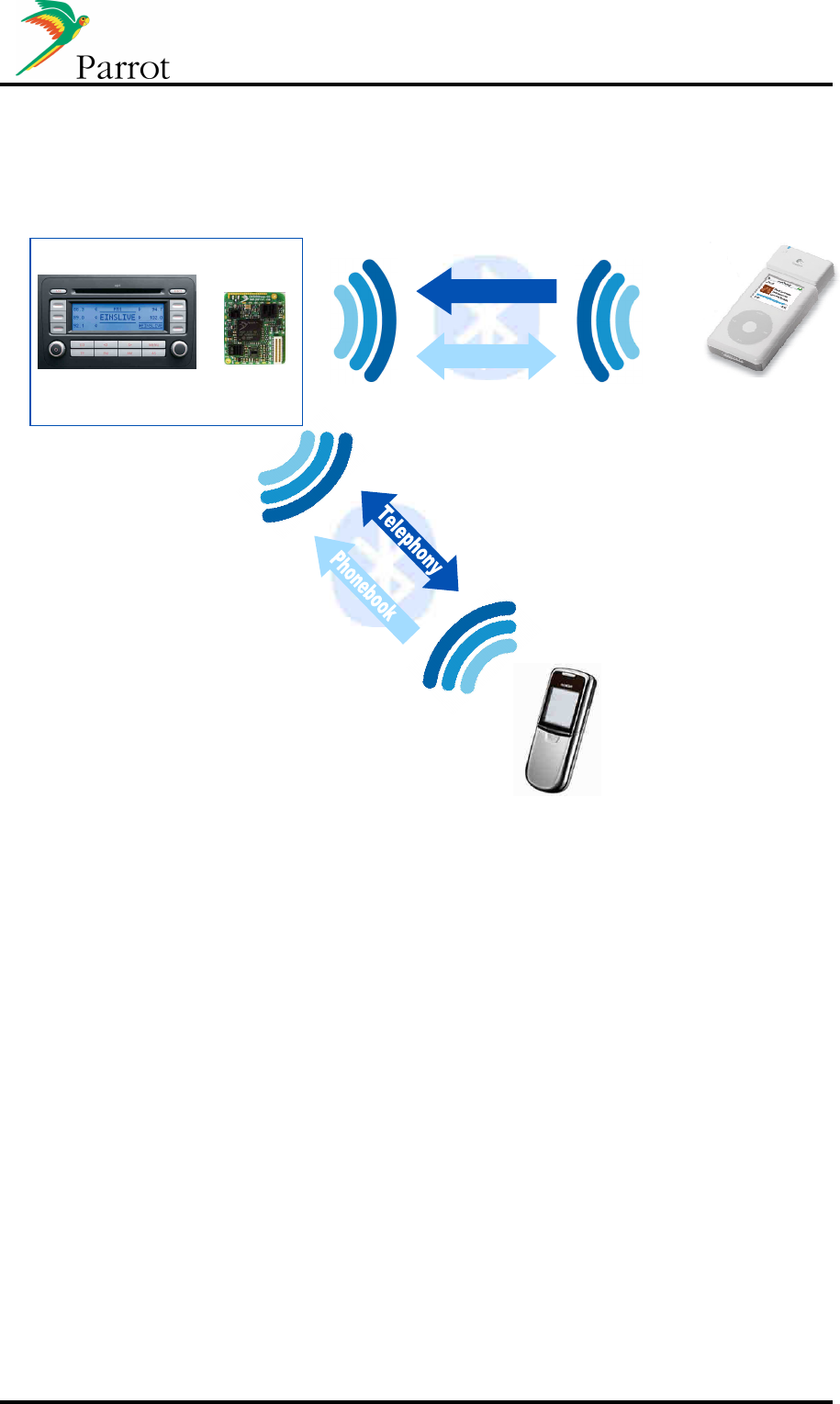
e. Head Unit paired with Mobile phone and Music Player with
Bluetooth dongle:
A2DP Source
A2DP Sink
Mobile Phone or
Music Player
Audio unit
MP3 or SBC (A2DP & AVRC
P
)
44
,1
kHz stereo
Streaming
Control
Phonebook synchro
Mobile phone
CK5050New & Host
Connection Management
Parrot Module is able to maintain two Bluetooth connections: one HFP to a phone (where the
phonebook synchronization is running after connection) and the other one with an A2DP
SRC Music Player. From the Module point of view, there are two users connected.
As stated with the Whitepaper, in this use case, the Module handles the AVHFP because the
A2DP SRC is not the connected phone. If the Bluetooth Music Player supports AVRCP TG,
Parrot alerts the HMI with Playback status and Metadata.
DATASHEET Confidential Information 42/49
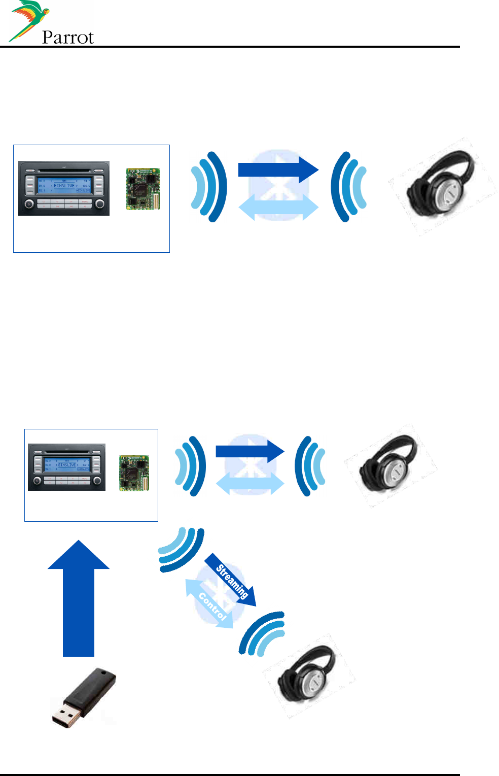
f. Head Unit paired with a stereo Headphone
Audio Streaming from Module to a stereo headphone
A2DP Sink
A2DP Source
Bluetooth
Headphones
Audio unit
MP3 or SBC (A2DP & AVRC
P
)
44,1 kHz stereo
Streaming
Control
CK5050New & Host
Parrot Module also embeds the A2DP SRC role, and then is able to play local music files to a
Sink device. Music file can be stored on a USB Stick, or can be routed from an iPod/iPhone
to the A2DP SNK.
g. Head Unit paired with two stereo Headphones
Audio streaming from Module to two Stereo Headphones simultaneously
A2DP Sink
A2DP Source
Bluetooth
Headphones
Audio unit
MP3 or SBC (A2DP & AVRCP
)
44,1 kHz stereo
Streaming
Control
Bluetooth
Headphones
A2DP Sink
Music files
transfer
(In this configuration, DISCO library is needed)
CK5050New Host

DATASHEET Confidential Information 43/49
The Module manages the A2DP SRC role, and establishes two A2DP connections with two
A2DP Sinks. The audio file is streamed at the same time to the two headsets.
This use case is dedicated to Music streaming rear seat entertainment.

DATASHEET Confidential Information 44/49
h. Head Unit paired with Mobile phone: Data transfer
Dial Up Networking: The Head Unit acts as data terminal with a connected gateway device,
typically a mobile phone.
DUN
Gateway
Data Terminal
Device
Mobile Phone
Audio unit
CK5050New Host
Data exchange
Data flow
Multi Profile Use
Parrot handles multiple Bluetooth connections. On the same device, it is possible to set up
both an HFP and a DUN connection.
According to the various Bluetooth implementations on phones, here is the description of
what is possible (given no phone limitations):
- DUN only:
o In this case, the phone acts as a Gateway and the Module forwards the data
to the Host (Data Terminal).
- HFP and DUN:
o If an incoming call occurs during the data transfer, there are three behaviors:
The call is established and data transfer continues without bandwidth
diminution.
The call is established and data transfer is stopped (AG gives priority
to HFP feature).
The distant caller reaches the voice mail of the connected phone
(phone limitation).
o If an outgoing call is requested by the user, the behaviors above also apply.
Those behaviors are described, phone by phone in the Parrot Bluetooth Compatibility Matrix with
all tested phones.
DATASHEET Confidential Information 45/49
B. USB/iPod Use Cases
Parrot DISCO Library handles the USB/iPod/iPhone connectivity, and gives to the Host the
ability to manage the music player.
When it is allowed by the protocol, DISCO is able to build a database from the music files
available on the device.
o
USB mass storage, SDCards, local file system: a database can be created, called the BSM
Database ("Base de Synchronization Musicale": in French for historical reason).
o
MTP (Media Transfer Protocol) devices: a similar database can be created.
o
iPods/iPhone: if the device is seen as a USB mass storage device, a database can be
created, otherwise we use the iAP (iPod Accessory Protocol) protocol and no database is
created.
a. Head Unit with a iPod connected through the USB
In this configuration, the Apple IC is required on
the motherboard. DISCO library is needed
DISCO library is needed)
USB Host and HandFree Device
Audio unit
Mobile phone
Audio
Control
CK5050New Host
iPod/iPhone Management
In this case, the Module directly accesses the iPod/iPhone database via iAP. Here are the
browsing modes offers by the Module:
- Artist (For all devices, including USB Mass Storage)
- Album
- Genre
- Playlist
- Title
- Podcast (only for iPod/iPhone)
- Composer

DATASHEET Confidential Information 46/49
- StartList (For USB)
- File System (For USB)
- Flat File System (For USB)
As for the phonebook, UTF8 is used to communicate this database to the Host
(independently if this is a USB or iPod database).
List of Compatible iPods
iPod Classic (3G), iPod Classic Photo (4G), iPod Classic Video (5G), iPod Classic (6G),
iPod Mini (1G), iPod Nano (1G), iPod Nano (2G), iPod Nano (3G), iPod Nano (4G), iPod
Touch (1G), iPod Touch (2G), iPhone, iPhone (3G).
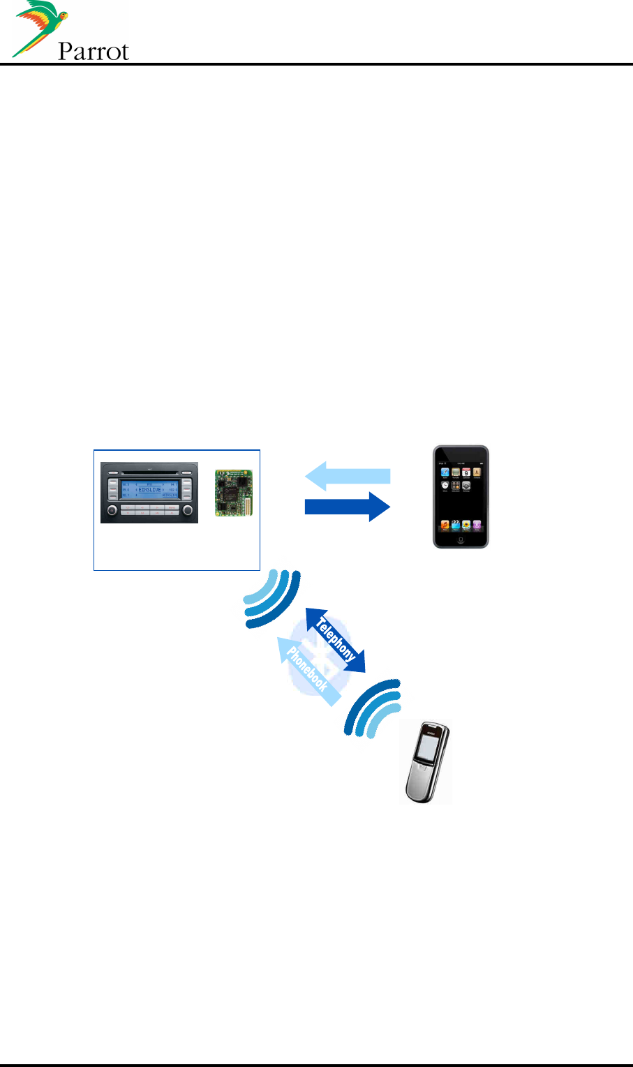
b. iPod & iPhones Use Cases
The iPhone/iPhone3G can be used as a Bluetooth AG and Music content at the same time.
In this case,
- First the user has to pair/connect its iPhone via Bluetooth to get the HFP features.
- Once HFP connection has been established, he can connect its iPhone to the
dedicated iPod connector, and the Module handles the browsing.
The user will have the Bluetooth HFP capacity and at the same time the possibility to browse
the iPod’s content.
Parrot releases more information about supported features in the Parrot Compatibility Matrix.
DATASHEET Confidential Information 47/49
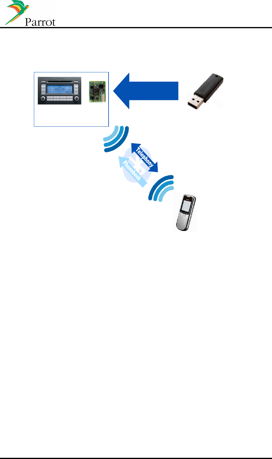
c. Head Unit paired with a connected USB Mass storage device
Music files
transfer
(In this configuration, DISCO library is needed)
USB Host and HandFree Device
Audio unit
Mobile phone
CK5050New & Host
Parrot music Management
Once the USB stick is plugged in for the first time, the Module reads the USB stick content,
parses music files, and gives the Host the access to the file system. Once this first parsing is
finished, the Module reparses music files, one by one, and builds the database using the
Metadata included in each file. The database is built according to this new parsing.
The Parrot Module provides the same set of commands for USB or iPods devices. The
implementation on the Host side is generic.
HFP and USB use at the same time
If a USB stick is plugged in while an HFP connection is already established with a phone, this
case is handled in two separate processes. Handsfree features are available while DISCO is
building the database in the background, without altering the Bluetooth link.
DATASHEET Confidential Information 48/49
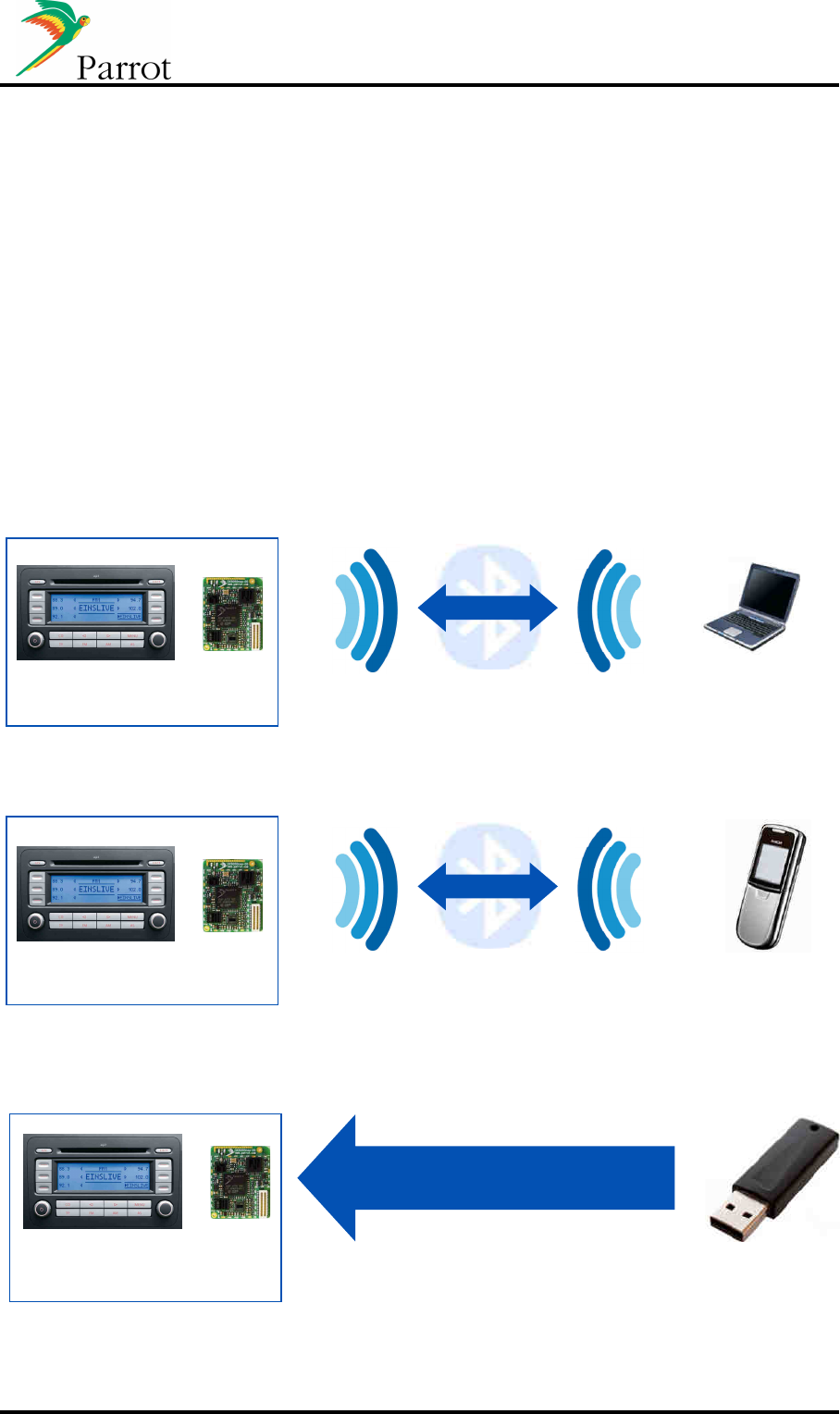
C. Head unit BT/USB software update
The firmware of Parrot modules can be updated in four different ways: by Bluetooth when paired with
a
Bluetooth-enabled
laptop, by DUN, USB or UART.
This is a very important feature of the Parrot Module. This ensures better Bluetooth
Compatibility with new phones coming on the Market. Some of these new phones need to
have a specific work-a-round when the Bluetooth specifications are not correctly
implemented on the phone (i.e. non-generic Bluetooth management).
Moreover, a major software update can include a new feature/profile (such as AVRCP1.4 for
instance) to give more compatibility or functionality to a car radio. This software update can
immediately be flashed (by Bluetooth, USB...) into your product already out in the market.
After the update, user settings (paired devices, phonebooks...) are not erased. This process
is transparent for the user.
Hands Free
update
Hands Free Device
Computer
Audio unit
CK5050New & Host
Update by Bluetooth or UART
D
ata flow
DUN
Gateway
Data Terminal
Device
Mobile Phone
Audio unit
CK5050New & Host
Data flow
Update by B
luetooth
USB Host and HandFree Device
Data
transfer
(In this configuration, the update file is stored in
the USB stick)
CK5050New & Host

DATASHEET Confidential Information 49/49
Methods available
- Bluetooth
o Via SPP
o Via FTP
o Via DUN (through a mobile phone connected to a server where is stored the
new software)
- Via USB with a standard USB Stick.
- Via UART with a host CPU that send the data
Secured update mechanism
The new software is copied into the flash Module’s memory but the previous software is not
affected by this copy. During this process, if an error occurs before the end of file transfer
(Bluetooth disconnection, data transfer stopped, USB Stick removed…), the Module will
restart with the previous software version.
The checksum of the new software is included into this new software. If the new file is
correctly written into the flash, when Module will reboots, the new checksum internally
calculated is compared the checksum of this new software. If checksum are equals, the new
file will overwrite the previous one. During this process, if power supply is turned off, the
remaining data will be continuing to be written where it has been stopped at the next boot.