PARROT FC6000N Bluetooth Module User Manual
PARROT Bluetooth Module
UserManual.wiki
>
PARROT
>
FC6000N User Manual
user manual
Navigation menu
Upload a User Manual
Namespaces
Wiki Guide
HTML
PDF
Info
Views
User Manual
Discussion / Help
Navigation
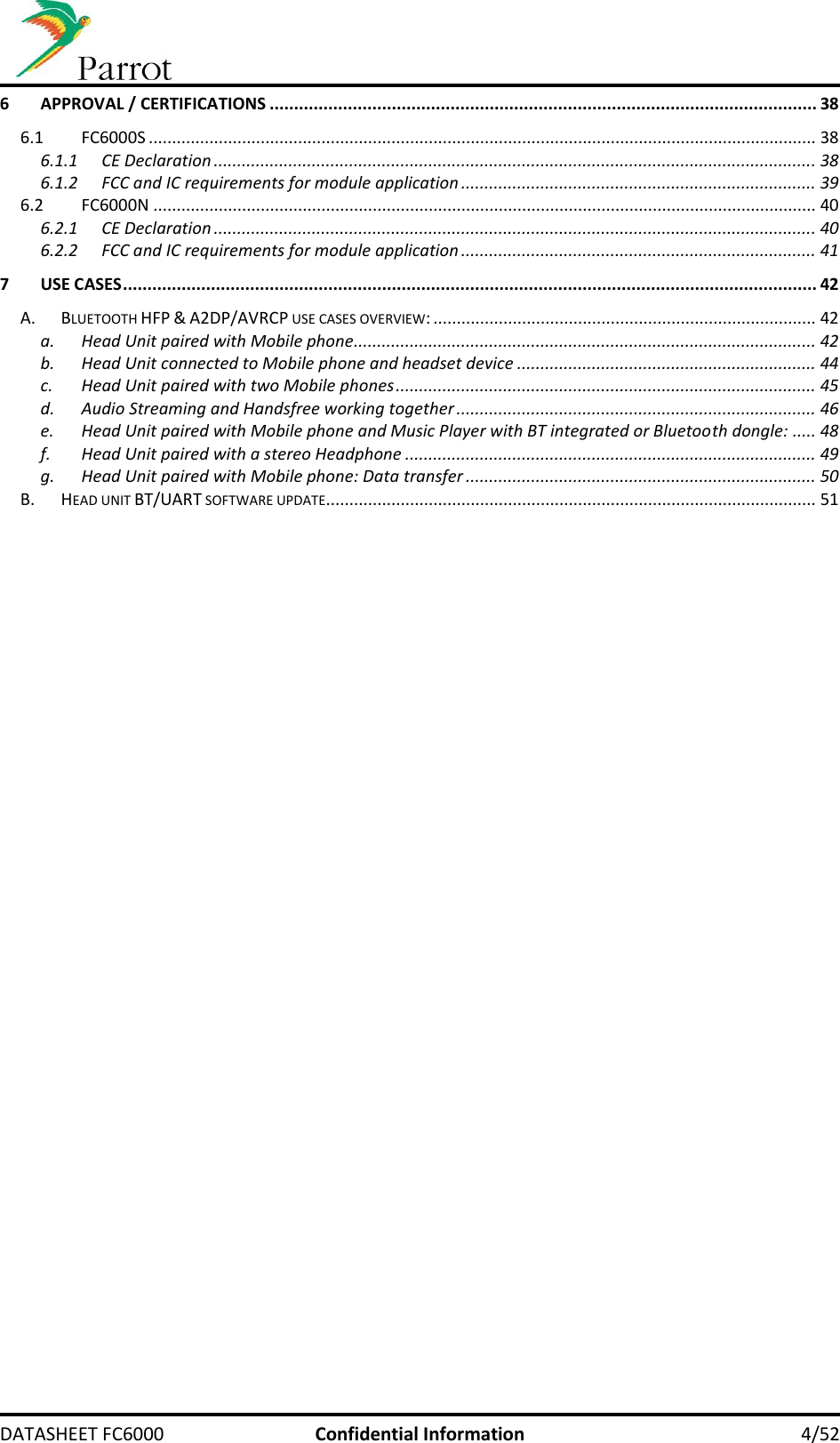
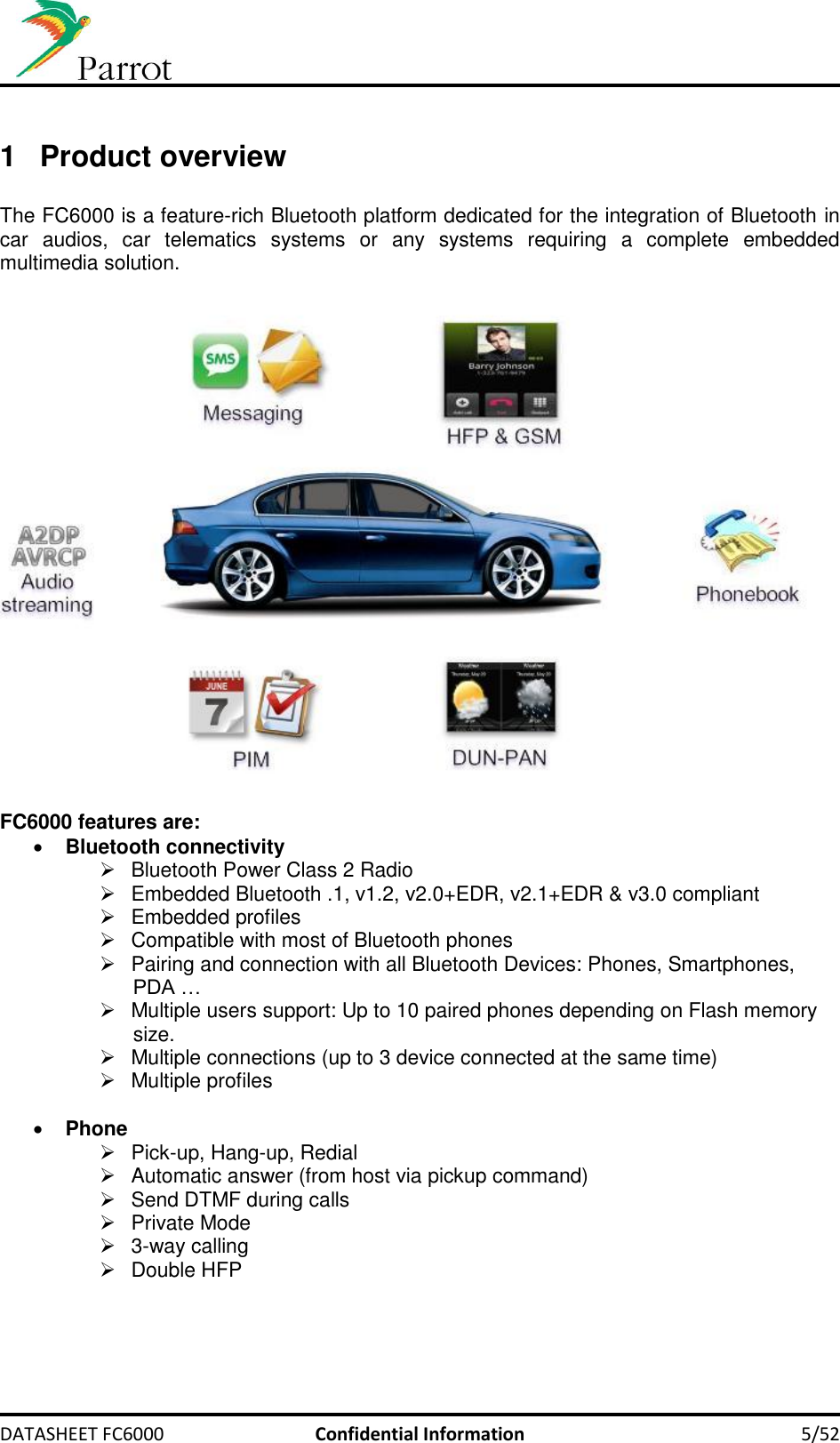
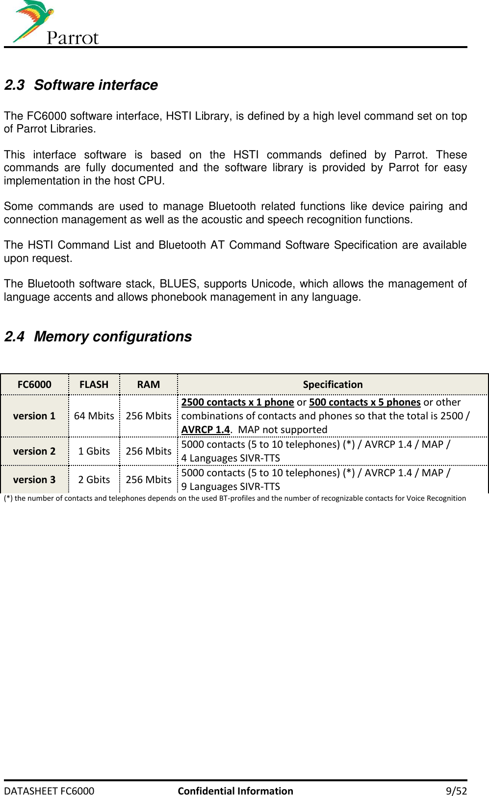
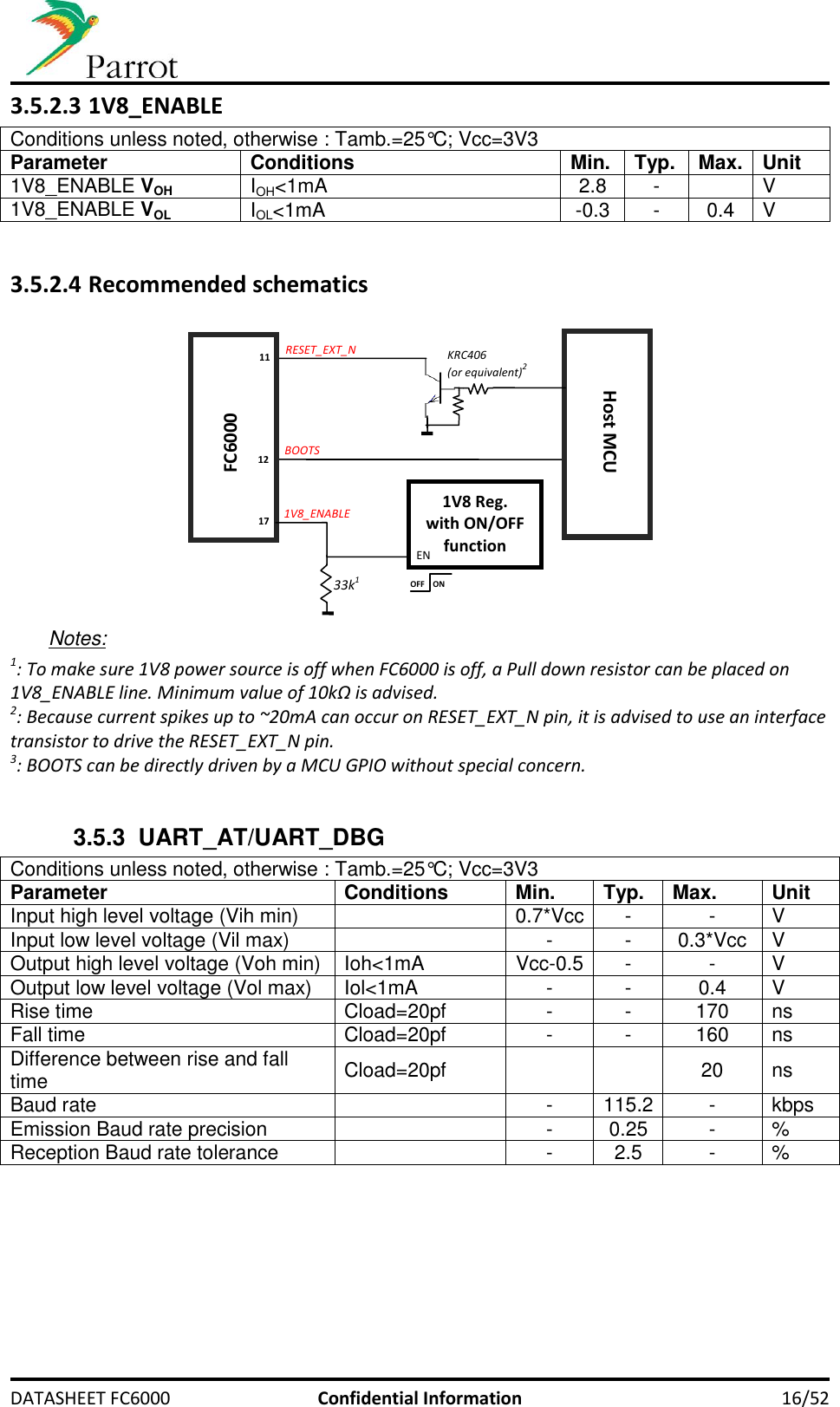
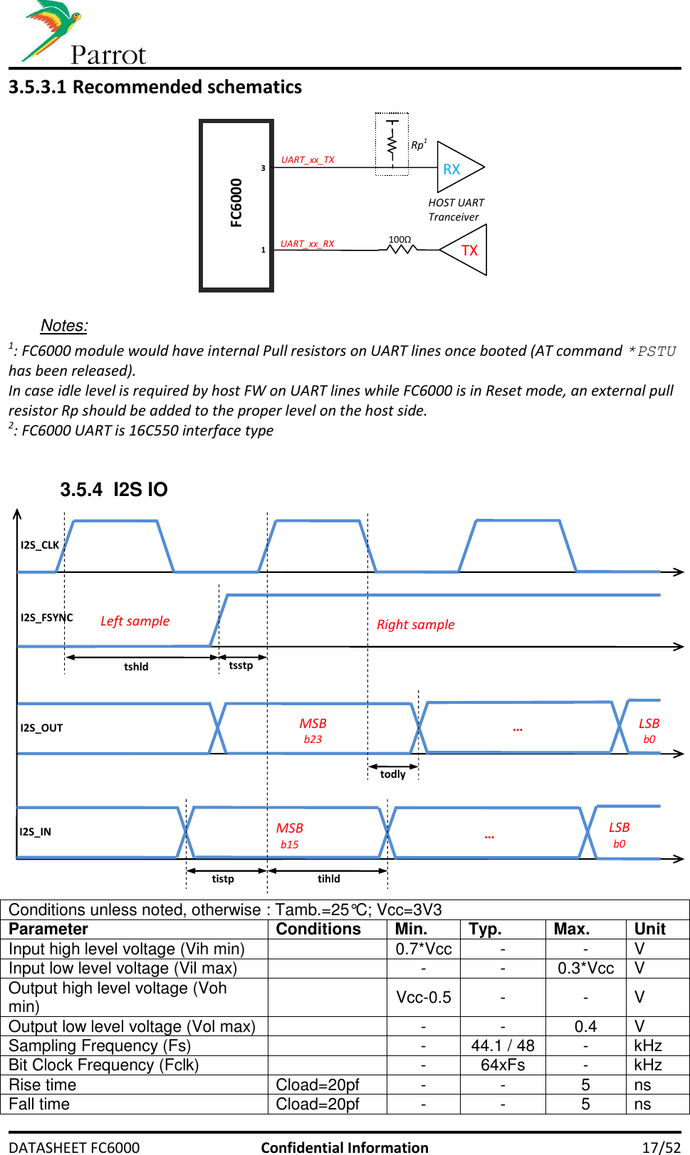
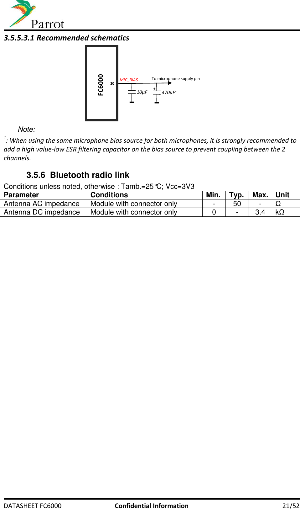
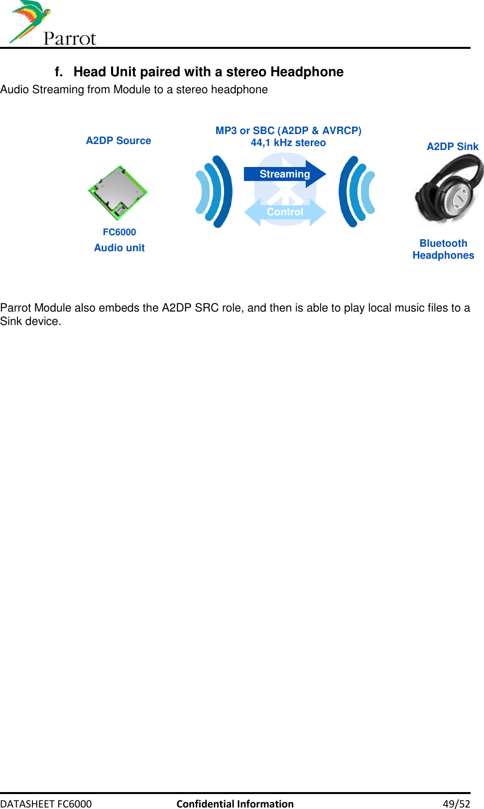
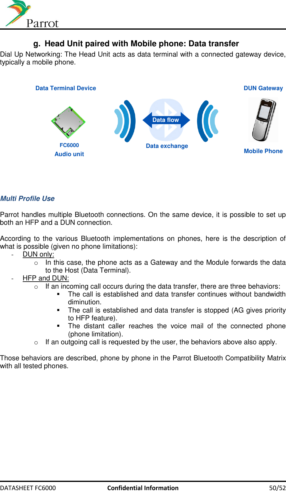
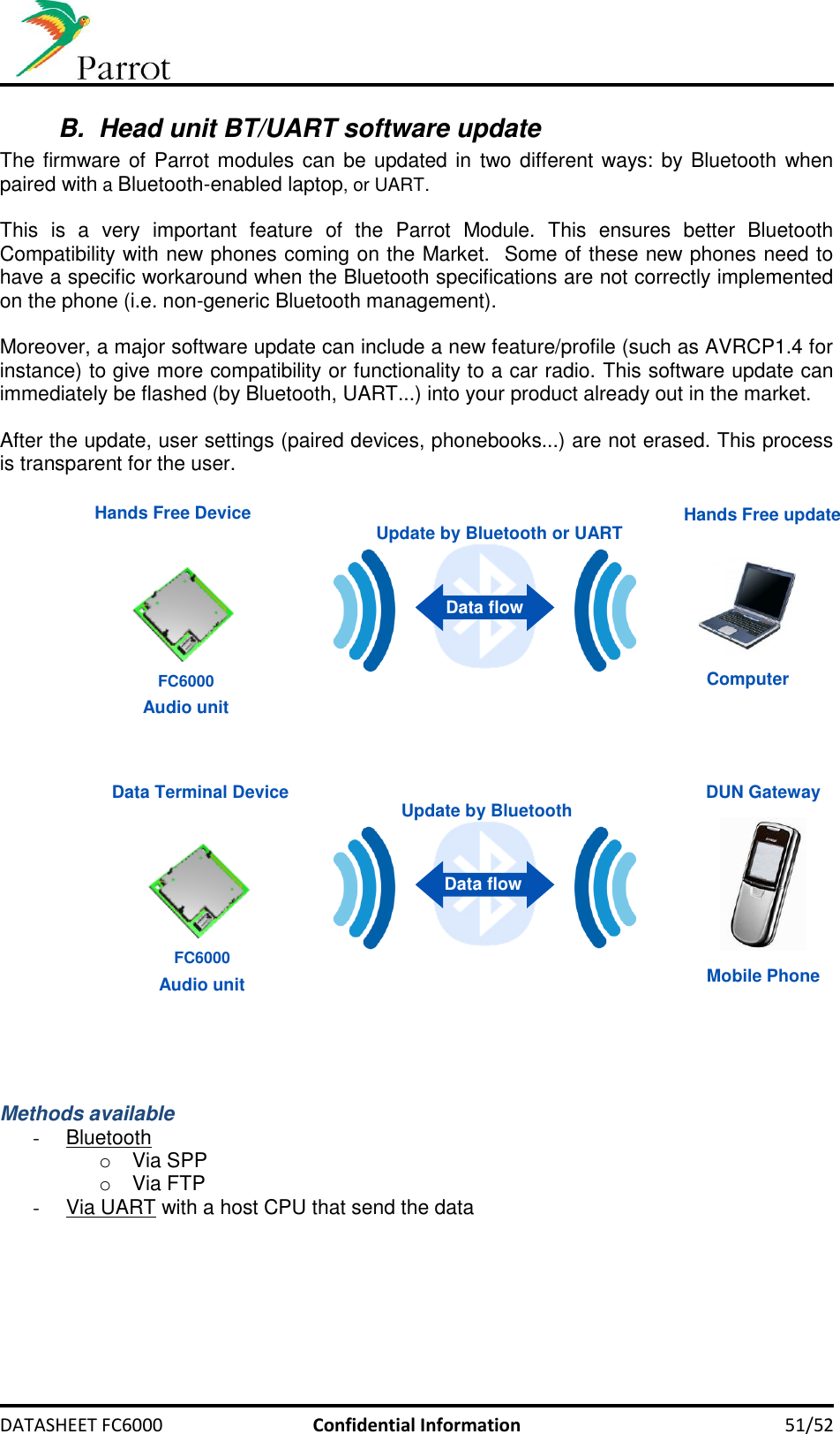
![DATASHEET FC6000 Confidential Information 20/52 3.5.5.2 Microphone input Conditions unless noted, otherwise : Tamb.=25°C; Vcc=3V3 (voice in ->I2S out) Parameter Conditions Min. Typ. Max. Unit Input impedance +30dB gain 7.1 - - kΩ Linear Dynamic Range 0dB gain 73 - - dB Maximum input signal 0dB gain 840 - 890 mVrms Low Cut-off Frequency 100nF capacitor on mother board - 20 250 Hz High Cut-off Frequency - - 3450 - Hz Signal to Noise Ratio @1kHz, 0.76Vrms 80 86 89 dB THD+N @1kHz, 0.76Vrms - 0.0054 0.1 % Crosstalk between channels @ 1kHz, 1Vrms - - -90 dB 3.5.5.2.1 Recommended schematics Notes: 1: For RP value, please look up your microphone datasheet 2: RH value comprises microphone’s output impedance plus an eventual serial resistor. For best response with voice input, please make sure that: 150Ω ≤ RH ≤ 680Ω to insure: 0.4dB ≤ Filter loss ≤ 1dB into the voice frequency range [0.3kHz ; 4kHz]. 3: We recommended using CB=10nF, and CH=560nF for best voice frequency response [0.3kHz ; 4kHz]. 4: When using single ended design, do not mount 5: When using single ended design, replace by short. 3.5.5.3 Microphone bias Conditions unless noted, otherwise : Tamb.=25°C; Vcc=3V3 Parameter Conditions Min. Typ. Max. Unit Bias voltage Vdd_codec = 3V, Ibias < 3mA 2.5 - 3 V Max load current - - 3 mA Coupling between channels MIC_PWR=MIC_BIAS 470 µF filtering capacitor, Rbias = 1kΩ @200Hz, 1Vrms - - -52 dB @1kHz, 1Vrms - - -61 MICx_P FC6000 RH 2,4 MICx_N RH 2 CB 3 CB 3,4 CB 3,4 CH 3 CH 3,4 MIC_PWR RP 1 RP 1,5 + 18/22 16/24](https://usermanual.wiki/PARROT/FC6000N/User-Guide-1670037-Page-20.png)