PARROT FC6000S Bluetooth Module User Manual FC6000 Datasheet version 1 5
PARROT Bluetooth Module FC6000 Datasheet version 1 5
PARROT >
User Manual

PARROT PRODUCT DATASHEET
Parrot
FC6000
Version 1.5
March 2011
Confidential Information
DATASHEET FC6000 Confidential Information 2/53
Ref: GC-2010-001
Parrot FC6000
All in one multimedia module
Bluetooth 3.0
Version 1.5
March 2011
FEATURES
Bluetooth 3.0 qualified module
3.3V & 1.8V power supply, UART, I²S
GPIO
Digital audio input and output
Analog microphone input
Analog output
Up to 10 paired phones
Small size module (32 x 36 mm)
Automotive qualified
Application:
• Telephony
• Internet access (through DUN or
PAN)
• Audio Streaming
• Voice Recognition / Text To
Speech
The FC6000 integrates the latest version
of the Parrot Bluetooth stack (Blues).
Blues gives to the customer a very high
level of compatibility with most of the
phones available on the market and
provide phonebook and list
synchronization. FC6000 offers the
possibility to use a Speaker Independent
Voice Recognition (SIVR) and a Text To
Speech algorithm (TTS).
Description:
Parrot FC6000 is a fully integrated
Bluetooth phone connectivity solution. It
integrates a large variety of interfaces for
an easy integration in most of the
applications.
Parrot
P6i
Flash
SDRAM
BT 2.1+EDR RF chip
Internal or external antenna
2*UART
I²S in/out
Analog microphone input
Analog output

DATASHEET FC6000 Confidential Information 3/53
Table of contents
1
PRODUCT OVERVIEW ............................................................................................................................... 5
2
SOFTWARE SPECIFICATIONS .................................................................................................................... 8
2.1
B
LUETOOTH STACK
...................................................................................................................................... 8
2.2
B
LUETOOTH PROFILE SUPPORTED
................................................................................................................... 8
2.3
S
OFTWARE INTERFACE
................................................................................................................................. 9
2.4
M
EMORY CONFIGURATIONS
......................................................................................................................... 9
2.5
S
PEAKER INDEPENDENT
V
OICE RECOGNITION
................................................................................................. 10
2.5.1
Voice Recognition principles ............................................................................................................ 10
2.5.2
Text To Speech (TTS) ........................................................................................................................ 11
3
ELECTRICAL SPECIFICATIONS .................................................................................................................. 12
3.1
H
ARDWARE ARCHITECTURE
......................................................................................................................... 12
3.2
P
IN
-
OUT
................................................................................................................................................. 12
3.2.1
Pin-out diagram .............................................................................................................................. 12
3.2.2
Pinout table ..................................................................................................................................... 13
3.2.3
Unconnected pins advice ................................................................................................................. 14
3.3
A
BSOLUTE
M
AXIMUM RATINGS
................................................................................................................... 15
3.4
P
OWER CONSUMPTION
(T°=25°C,
1V8
PROVIDED BY
DC/DC
MPS2128) ........................................................ 15
3.4.1
Power consumption on 3V3 Power Supply ...................................................................................... 15
3.4.2
Power consumption on 1V8 Power Supply ...................................................................................... 15
3.5
E
LECTRICAL CHARACTERISTICS
..................................................................................................................... 15
3.5.1
Power pins ....................................................................................................................................... 15
3.5.2
Reset pin .......................................................................................................................................... 15
3.5.3
IO pins.............................................................................................................................................. 16
3.5.4
UART_AT/UART_DBG ...................................................................................................................... 16
3.5.5
I2S IO ............................................................................................................................................... 17
3.5.6
Audio ............................................................................................................................................... 18
3.5.7
Bluetooth radio link ......................................................................................................................... 18
3.6
R
ESET AND SUPPLY SEQUENCE DIAGRAM
....................................................................................................... 19
3.7
F
LASH UPDATE SEQUENCE DIAGRAM
............................................................................................................. 20
3.8
P
OWER
O
FF
S
EQUENCE DIAGRAM
................................................................................................................ 20
3.9
M
OTHERBOARD
E
LECTRICAL
I
NTEGRATION
.................................................................................................... 21
3.9.1
Connector ........................................................................................................................................ 21
3.9.2
Power stage ..................................................................................................................................... 22
3.9.3
Microphone ..................................................................................................................................... 24
3.9.4
Line out ............................................................................................................................................ 25
3.9.5
I2S .................................................................................................................................................... 25
3.9.6
UARTs .............................................................................................................................................. 25
3.9.7
Boots ............................................................................................................................................... 26
3.9.8
Reset Pin .......................................................................................................................................... 26
4
MECHANICAL SPECIFICATIONS ............................................................................................................... 27
4.1
H
ORIZONTAL MODULE WITH EXTERNAL ANTENNA
............................................................................................ 28
4.2
H
ORIZONTAL MODULE WITH INTERNAL ANTENNA
............................................................................................ 29
4.3
V
ERTICAL MODULE WITH EXTERNAL ANTENNA
................................................................................................ 30
4.4
V
ERTICAL MODULE WITH INTERNAL ANTENNA
................................................................................................. 31
4.5
M
ODULE CONNECTORS
.............................................................................................................................. 32
4.5.1
Connector on mother board ............................................................................................................ 32
4.5.2
Horizontal modules connector ........................................................................................................ 33
4.5.3
Vertical modules connector ............................................................................................................. 34
4.5.4
Antenna connector .......................................................................................................................... 35
4.6
M
OTHERBOARD
M
ECHANICAL
I
NTEGRATION
................................................................................................. 36
4.6.1
Mechanical integration – Horizontal version: ................................................................................. 36

DATASHEET FC6000 Confidential Information 4/53
4.6.2
Mechanical integration – Vertical version:...................................................................................... 37
5
AVAILABLE TOOLS .................................................................................................................................. 38
5.1
W
ORKBENCH
........................................................................................................................................... 38
5.1.1
Diagram ........................................................................................................................................... 38
5.1.2
Schematics ....................................................................................................................................... 39
5.2
W
X
H
IP
H
OP
............................................................................................................................................. 40
5.3
W
X
F
LASHER
............................................................................................................................................ 40
6
APPROVAL / CERTIFICATIONS ................................................................................................................ 41
6.1
CE
D
ECLARATION
..................................................................................................................................... 41
6.2
FCC
AND
IC
REQUIREMENTS FOR MODULE APPLICATION
................................................................................... 42
7
USE CASES .............................................................................................................................................. 43
A.
B
LUETOOTH
HFP
&
A2DP/AVRCP
USE CASES OVERVIEW
: .................................................................................. 43
a.
Head Unit paired with Mobile phone................................................................................................... 43
b.
Head Unit connected to Mobile phone and headset device ................................................................ 45
c.
Head Unit paired with two Mobile phones .......................................................................................... 46
d.
Audio Streaming and Handsfree working together ............................................................................. 47
e.
Head Unit paired with Mobile phone and Music Player with BT integrated or Bluetooth dongle: ..... 49
f.
Head Unit paired with a stereo Headphone ........................................................................................ 50
g.
Head Unit paired with Mobile phone: Data transfer ........................................................................... 51
B.
H
EAD UNIT
BT/UART
SOFTWARE UPDATE
......................................................................................................... 52
DATASHEET FC6000 Confidential Information 5/53
1 Product overview
The FC6000 is a feature-rich Bluetooth platform dedicated for the integration of Bluetooth in
car audios, car telematic systems or any systems requiring a complete embedded
multimedia solution.
FC6000 features are:
• Bluetooth connectivity
Bluetooth Power Class 2 Radio
Embedded Bluetooth .1, v1.2, v2.0+EDR, v2.1+EDR & v3.0 compliant
Embedded profiles
Compatible with most of Bluetooth phones
Pairing and connection with all Bluetooth Devices: Phones, Smartphones,
PDA …
Multiple users support: Up to 10 paired phones depending on Flash memory
size.
Multiple connections (up to 3 device connected at the same time)
Multiple profiles
• Phone
Pick-up, Hang-up, Redial
Automatic answer (from host via pickup command)
Send DTMF during calls
Private Mode
3-way calling
Double HFP

DATASHEET FC6000 Confidential Information 6/53
• Phone Book
Automatic Phone book synchronization over Bluetooth (up to 5000 contacts;
depending on the Flash memory size)
Call history (dialed number, received calls, missed calls)
All Synchronization Methods
Full Unicode for compatibility with numerous characters sets (European,
Russian, Chinese, Japanese…)
• Digital Signal Processing
Microphone(s): the module can manage two configurations:
Single microphone
Two microphones with AMS (Automatic Microphone Selection): 1 for
the driver and 1 for the front seat passenger. The best microphone is
automatically selected during the call.
Noise Reduction (NR)
Maximal NR is 25dB.
Typical NR is 15dB.
No musical noise
No fluctuation of the residual noise level
Automatic adaptation of the Noise Reduction to the Signal-to-noise
ratio (SNR) to keep the best voice quality in idle and remove more
noise in noisy conditions.
Acoustic Echo Cancellation (AEC)
The level of echo attenuation, called ERLE is 45dB (measured
according to the VDA process).
Comfort Noise feature so that the background noise is adjusted after
AEC algorithm, in order to keep it constant for enhanced
communication experience.
Possibility to accept up to 100ms of delay in the speaker path for digital
amplifiers.
Full duplex
Automatic Level Control (ALC)
Different phones can have different Speaker volumes (up to 20dB of
difference). It adapts the signal level received from the phone to the
target level, quickly and precisely.
Equalizer
9 bands equalizer for microphones and speaker paths.
Tuning
Car independent tuning if the microphone position and specifications
are the same.
Possibility to tune all parameters of the audio algorithms according to
Customer preferences.
Wideband
All algorithms work @ 16 kHz.
• Audio Streaming
Embedded SBC decoder
Embedded MP3 decoder from Thomson Licensing (optional)
Stereo audio output
• Speaker Independent Voice Recognition (Optional)
• Text To Speech (Optional)

DATASHEET FC6000 Confidential Information 7/53
• Miscellaneous
Provide Phone Battery Level and Network Level, Carrier Name (depends on
phones)
• Software Update
Full standard Software available (free upgrade from Parrot homepage)
Software update available through Bluetooth or UART
Very large compatibility with Phones, Smart phones, PDAs, Music players
• External Bluetooth Antenna connection diagnostic
• HSTI
In order to facilitate communication between the FC6000 and your product host
microprocessor, Parrot has created and provides the HSTI Library. The HSTI library
is the software application programming interface (API) to integrate the FC6000
command and control within the software of the host processor.
HSTI is backward compatible with former AT commands. Few adaptations may be
considered due to the improvements in the new modules generation. Application
notes are available.

DATASHEET FC6000 Confidential Information 8/53
2 Software specifications
2.1 Bluetooth stack
• HCI (Host Controller interface),
• L2CAP (Logical Link Control and Adaptation Protocol),
• RFCOMM
• SDP (Service Discovery Protocol),
• OBEX (IrDA Object Exchange).
• Channel manager, AMP Manager, HCI AMP (BT 3.0 software).
• HCI Read Encryption Key Size command (BT 3.0 software).
2.2 Bluetooth profile supported
• Generic Access Profile
• Phone Management
HFP 0.96 / 1.0 / 1.5
Multi-HFP
1
HSP 1.0 / 1.2
SAP (SIM Access Profile) 1.1
2
• Message Management
MAP 1.0 (optional)
• Phone Book
PBAP 1.0 / 1.1
SYNC 1.1 (IrMC SYNC over BT)
SYNCML
OPP Server/Client (Vcard 3.0) 1.0 / 1.1 / 1.2
GSM 07.07 AT Commands
Nokia synchronization protocol
• Multimedia
A2DP (Audio) 1.2
SBC decoding
(optional MP3 decoding)
AVDTP 1.2
AVRCP 1.0 / AVRCP 1.3 / AVRCP 1.4
• Others
SPP 1.1
BNEP, PAN 1.0
FTP 1.0 / 1.1 / 1.2
Image transfer over OPP
3
DUN 1.1
Software update over FTP
Secure Simple Pairing
1
Only For Nand Version
2
Only For Nand Version
3
Only For Nand Version
DATASHEET FC6000 Confidential Information 9/53
2.3 Software interface
The FC6000 software interface, HSTI Library, is defined by a high level command set on top
of Parrot Libraries.
This interface software is based on the HSTI commands defined by Parrot. These
commands are fully documented and the software library is provided by Parrot for easy
implementation in the host CPU.
Some commands are used to manage Bluetooth related functions like device pairing and
connection management as well as the acoustic and speech recognition functions.
The HSTI Command List and Bluetooth AT Command Software Specification are available
upon request.
The Bluetooth software stack, BLUES, supports Unicode, which allows the management of
language accents and allows phonebook management in any language.
2.4 Memory configurations
FC6000 FLASH RAM Specification
version 1 32 Mbits
64 Mbits
3000 contacts x 1 phone or 600 contacts x 5 phones or other
combinations of contacts and phones so that the total is 3000 /
AVRCP 1.4. MAP not supported
In case the H
ost
provides available
flash memory for pho
nebook
storage, the system (Host + FC6000) can store up to 2500 contacts
per phone x up to 10 phones (depending on the Host flash size
available) / AVRCP 1.4. MAP not supported
version 2 1 Gbits 128 Mbits
5000 contacts (5 to 10 telephones) (*) / AVRCP 1
.4
/
MAP
version 3 1 Gbits 256 Mbits
5000 contacts (5 to 10 telephones) (*) /
AVRCP 1.4
/
MAP
/
4 Languages SIVR-TTS
version 4 2 Gbits 256 Mbits
5000 contacts (5 to 10 telephones) (*) /
AVRCP 1.4
/
MAP
/
9 Languages SIVR-TTS
(*) the number of contacts and telephones depends on the used BT-profiles and the number of recognizable contacts for Voice Recognition
DATASHEET FC6000 Confidential Information 10/53
2.5 Speaker independent Voice recognition
2.5.1 Voice Recognition principles
2.5.1.1 Description
VoCon 3200 V3.3 is NUANCE training-less speaker independent speech recognition
algorithm.
• Phonemes recognition: words are recognized without previous training
• Words models for a better precision, especially for digits recognition
• Continuous voice recognition: no need for blanks between words
• New words learning (Voice tags), speaker dependent speech recognition (100 Voice
tags, 2kbytes by Voice tag)
• Noise robustness and accuracy in an automotive environment: engine, click-button
etc…
• Highly accurate recognition
• VoCon Music Pre-Processor. This feature allows the user to select music to play by
voice commands.
2.5.1.2 Operation
During a voice recognition process, "Feature Extraction" module decomposes the signal. The
module "Search" looks for the equivalent text using the modules "G2P" and "Grammar to
compile". These two modules are using the libraries "Acoustic Model", "Lexicon" and
"Grammar".
Module G2P ensures equivalence between the graphemes and the phonemes.
For each language is associated an acoustic model ("Acoustic Model"), a grammar and a
lexicon ("Grammar" and "Lexicon").
System feedback is realized by a screen display and/or sounds (synthesized voice, chime,
pre-recorded voice prompts…).
Operation is ended by a final action (phone number dialing, radio station tuning…).

DATASHEET FC6000 Confidential Information 11/53
2.5.2 Text To Speech (TTS)
Text to Speech (TTS) on FC6000 is based on SVOX Automotive Speech.
SVOX Automotive TTS solutions are tailored for noisy car environments and enjoy a
reputation for industry-leading quality. They power many of the most advanced and
successful in-dash infotainment systems in the market. SVOX TTS technology is
characterized by natural and clear sound as well as unique polyglot capability – the same
voice can speak multiple languages like a native speaker.
It is not limited in vocabulary. It can be used to confirm the orders identified by a voice
recognition process or for reading vehicle commands, songs titles or phonebook entries.
Please find below Voice Recognition and TTS languages available in FC6000:
01) ENU US English
02) FRC CA French
03) SPM N.A. Spanish
04) ENG UK English
05) FRF French
06) ITI Italian
07) GED German
08) SPE Spanish
09) DUN Dutch
10) DAD Danish
11) SWS Swedish
12) PTP Portuguese
13) PTB Brazilian
Portuguese
14) TRT Turkish
15) RUR Russian
16) PLP Polish
17) CZC Czech
18) MNC Mandarin Chinese
19) KOK Korean
20) JPN Japanese
DATASHEET FC6000 Confidential Information 12/53
3 Electrical specifications
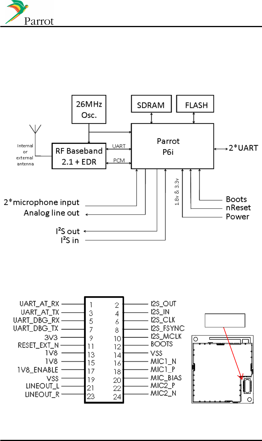
3.1 Hardware architecture
3.2 Pin-out
3.2.1 Pin-out diagram
Pin N. 1

DATASHEET FC6000 Confidential Information 13/53
3.2.2 Pinout table
PIN
SIGNAL PIN
TYPE
FUNCTION
Typical
Voltage
Maximal
Current
1 UART_AT_RX I AT Commands & flash update UART input
(Note 1)
(Note 1)
2 I2S_OUT O Digital audio data output
(Note 2)
(Note 2)
3 UART_AT_TX O
AT Commands & flash update UART
output
(Note 1)
(Note 1)
4 I2S_IN I Digital audio data input
(Note 2)
(Note 2)
5 UART_DBG_RX I Debug UART input
(Note 1)
(Note 1)
6 I2S_CLK O
Digital audio main clock (Module is used
to be set as master)
(Note 2)
(Note 2)
7 UART_DBG_TX O Debug UART output
(Note 1)
(Note 1)
8 I2S_SYNC IO
Digital audio synchronization clock
(Module is used to be set as master)
(Note 2)
(Note 2)
9 3V3 P Positive power supply : 3,3V
3.3V
110
mA
10 I2S_MCLK O
Digital audio master clock (Module is
used to be set as master)
(Note 2)
(Note 2)
11 RESET_EXT_N I Reset signal – Active Low
(Note 3)
(Note 3)
12 BOOTS I Boot mode selection signal – Active High
3.3V
80
μ
A
13 1V8 P Positive power supply : 1V8
1.8V
630mA
14 VSS P Power supplies ground
0V
740mA
15 1V8 P Positive power supply : 1V8
1.8V
630mA
16 MIC1_N AI Negative differential Microphone input 1
0
-
50mV
5
μ
A
17 1V8_ENABLE O
1V8 Power Supply Enable signal
–
Active
High
(Note 4)
(Note 4)
18 MIC1_P AI Positive differential Microphone input 1
0
-
50mV
5
μ
A
19 VSS P Power supplies ground
0V
740mA
20 MIC_BIAS AO Microphones bias voltage
2.8V
3mA
21 LINEOUT_L AO Analog audio stereo output, left channel
0
-
560mV
100
μ
A
22 MIC2_P AI Positive differential Microphone input 2
0
-
50mV
5
μ
A
23 LINEOUT_R AO Analog audio stereo output, right channel
0
-
560mV
100
μ
A
24 MIC2_N AI Negative differential Microphone input 2
0
-
50mV
5
μ
A
Legend:
I
Input
AI
Analog Input
O
Output
AO
Analog Output
IO
Input/Output
P
Power
Note1: See section 3.5.4
Note2: See section 3.5.5
Note3: See section 3.5.2
Note4: See section 3.5.3.2

DATASHEET FC6000 Confidential Information 14/53
3.2.3 Unconnected pins advice
PIN FUNCTION PIN TYPE COMMENT
1
UART_AT_RX
I
N/A
2
I2S_OUT
O
Left Open
3
UART_AT_TX
O
N/A
4
I2S_IN
I
Left Ope
n
5
UART_DBG_RX
I
Left Open
6
I2S_CLK
O
Left Open
7
UART_DBG_TX
O
Left Open
8
I2S_SYNC
I
O
Left Open
9
P3V3
P
N/A
10
I2S_MCLK
O
Left Open
11 RESET_EXT_N I Left Open
12
BOOTS
I
Tie to ground
13
P1V8
P
N/A
14
VSS
P
N/A
15
P1V8
P
N/A
16
MIC1_N
I
T
ie to ground (1k)
17
1V8_ENABLE
O
N/A
18
MIC1_P
I
Tie to ground (1k)
19
VSS
P
N/A
20
MIC_BIAS
O
Left Open
21
LINEOUT_L
O
Left Open
22
MIC2_P
I
Tie to ground (1k)
23
LINEOUT_R
O
Left Open
24
MIC2_N
I
Tie to ground (1k)

DATASHEET FC6000 Confidential Information 15/53
3.3 Absolute Maximum ratings
Operating temperature range ........................................................................... -40°C to +85°C
Storage temperature range ............................................................................ -40°C to +125°C
Voltage on Vcc with respect to Vss ...................................................................... 3.1V to 3.6V
ESD sensitivity according ESD Association AEC Q100 ....................... ±2kV HBM / ±200V MM
3.4 Power consumption
(T°=25°C, 1V8 provided by DC/DC MPS2128)
3.4.1 Power consumption on 3V3 Power Supply
Stop mode (reset pin low) ............................................................................................... <6mA
Run mode (waiting for commands) ............................................................................... <40mA
Hands free and audio streaming mode ....................................................................... <120mA
Peak current at startup (128µs) .................................................................................... 110mA
3.4.2 Power consumption on 1V8 Power Supply
Stop mode (reset pin low) ................................................................................................. 0mA
Run mode (waiting for commands) ............................................................................... <60mA
Hands free and audio streaming mode ....................................................................... <150mA
Peak current at startup (190µs) .................................................................................... 630mA
3.5 Electrical characteristics
3.5.1 Power pins
Conditions unless noted, otherwise : Tamb.=25°C
Parameter
Conditions
Min.
Typ.
Max.
Unit
3V3 power supply 3.1 3.3 3.6 V
1V8 power supply 1.71 1.8 1.89 V
3.5.2 Reset pin
Conditions unless noted, otherwise : T=-40°C to +85 °C; Vcc=3V1 to 3V6
Parameter
Conditions
Min.
Typ.
Max.
Unit
Active reset time (tRA) 50 - - µs
Active reset voltage level - - 0.89 V
Non active reset voltage level 2.54 - - V

DATASHEET FC6000 Confidential Information 16/53
3.5.3 IO pins
3.5.3.1 BOOTS
Conditions unless noted, otherwise : Tamb.=25°C; Vc c=3V3
Parameter
Conditions
Min.
Typ.
Max.
Unit
BOOTS
V
iH
1.24 - 3.6 V
BOOTS
V
iL
-0.3 - 0.60 V
3.5.3.2 1V8_ENABLE
Conditions unless noted, otherwise : Tamb.=25°C; Vc c=3V3
Parameter
Conditions
Min.
Typ.
Max.
Unit
1V8_ENABLE
V
O
H
2.9 - V
1V8_ENABLE
V
O
L
-0.3 - 0.4 V
3.5.4 UART_AT/UART_DBG
Conditions unless noted, otherwise : Tamb.=25°C; Vc c=3V3
Parameter
Conditions
Min.
Typ.
Max.
Unit
Input high level voltage (Vih min) 0.7*Vcc
- - V
Input low level voltage (Vil max) - - 0.2*Vcc
V
Output high level voltage (Voh min) Vcc-0.4
- - V
Output low level voltage (Vol max) - - 0.4 V
Output high level current (Ioh max) Voh>Vcc-0.4 5.45 - 32.1 mA
Output low level current (Iol max) Vol<0.4 5.45 - 33.4 mA
Rise time Cload=20pf - - 170 ns
Fall time Cload=20pf - - 160 ns
Baud rate - 115.2
460.8 kbps
Emission Baud rate precision - 0.25 - %
Reception Baud rate tolerance - 2.5 - %
DATASHEET FC6000 Confidential Information 17/53
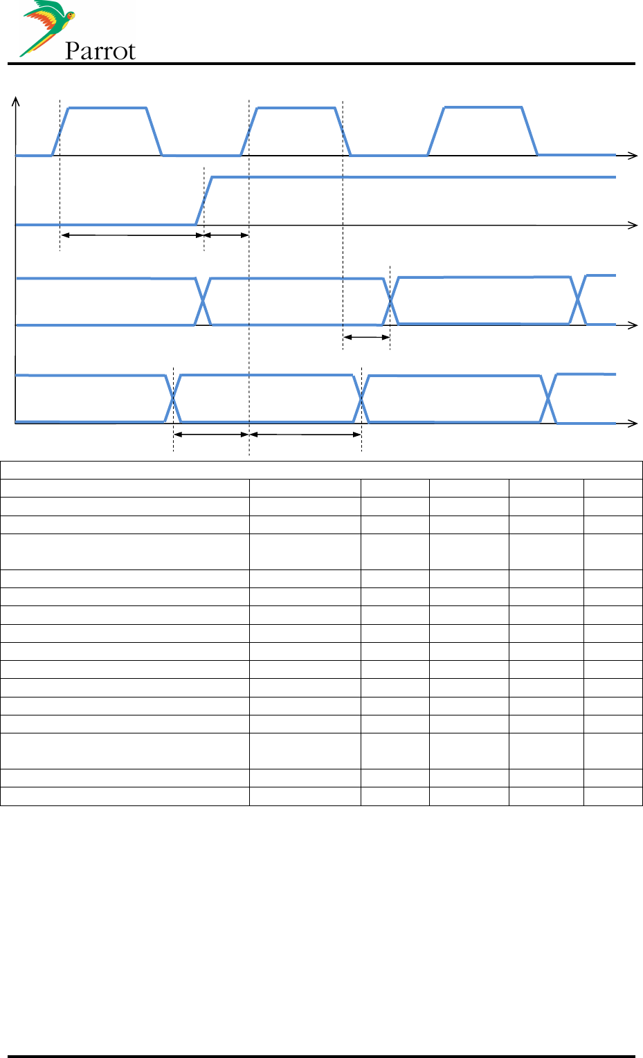
3.5.5 I2S IO
Conditions unless noted, otherwise : Tamb.=25°C; Vc c=3V3
Parameter
Conditions
Min.
Typ.
Max.
Unit
Input high level voltage (Vih min) 0.7*Vcc
- - V
Input low level voltage (Vil max) - - 0.2*Vcc V
Output high level voltage (Voh
min) Vcc-0.4
- - V
Output low level voltage (Vol max) - - 0.4 V
Output high level current (Ioh max)
Voh>Vcc-0.4 5.45 - 32.1 mA
Output low level current (Iol max) Vol<0.4 5.45 - 33.4 mA
Sampling Frequency (Fs) - 44.1 / 48 - kHz
Bit Clock Frequency (Fclk) - 64xFs - kHz
Rise time Cload=20pf - - 5 ns
Fall time Cload=20pf - - 5 ns
SYNC_CLK hold time (tshld) 10 - - ns
SYNC_CLK setup time (tsstp) 10 - - ns
I2S_OUT propagation delay
(todly) - - 10 ns
I2S_IN setup time (tistp) 10 - - ns
I2S_IN hold time (tihld) 10 - - ns
BCLK
SYNC_CLK
I2S_OUT
I2S
tshld
t
sstp
t
o
d
ly
tistp tihld
Right sample
Left sample
MSB
b23
…
…
LSB
b0
MSB
b15
LSB
b0

DATASHEET FC6000 Confidential Information 18/53
3.5.6 Audio
3.5.6.1 Analog out
Conditions unless noted, otherwise : Tamb.=25°C; Vc c=3V3
Parameter
Conditions
Min.
Typ.
Max.
Unit
Maximum output level - - 0.41 Vrms
Drive load capability Lineout to agnd,
AC coupled
7 10 - kΩ
- 30 1000 pF
High Cut-off Frequency (-3dB) 19.99kHz
@Fs=44.1kHz - =0.4535xFs
- Hz
Signal to Noise Ratio @1kHz,
340mVrms - 65 - dB
THD+N @1kHz,
340mVrms - 0.03 - %
Noise level - 104 - µV
Crosstalk between channels - -80 - dB
3.5.6.2 Microphone input
Conditions unless noted, otherwise : Tamb.=25°C; Vc c=3V3
Parameter
Conditions
Min.
Typ.
Max.
Unit
Maximum input level +30dB gain on
module - - 30 mVrms
Input impedance +30dB gain on
module 7.1 - kΩ
Low Cut-off Frequency (-3dB) 1µF capacitor on
mother board - 16 18 Hz
High Cut-off Frequency (-3dB) 19.99kHz
@Fs=44.1kHz - =0.4535xFs
- Hz
Signal to Noise Ratio @1kHz, 30mVrms - 75 - dB
THD+N @1kHz, 30mVrms - 0.04 - %
3.5.6.3 Microphone bias
Conditions unless noted, otherwise : Tamb.=25°C; Vc c=3V3
Parameter
Conditions
Min.
Typ.
Max.
Unit
Bias voltage Vdd_codec = 3V 2.7 - 3 V
Max load current - - 3 mA
Microphone bias filter
low cut off frequency 470µF capacitor
on mother board - - 4.5 Hz
3.5.7 Bluetooth radio link
Conditions unless noted, otherwise : Tamb.=25°C; Vc c=3V3
Parameter
Conditions
Min.
Typ.
Max.
Unit
Antenna AC impedance Module with connector only - 50 - Ω
Antenna DC impedance Module with connector only - - 28.5 kΩ
DATASHEET FC6000 Confidential Information 19/53
3.6 Reset and supply sequence diagram
Conditions unless noted, otherwise : Tamb.=25°C; Vc c=3V3
Paramet
er
Conditions
Min.
Typ.
Max.
Uni
t
tRA 50 - - µs
tPOR - - 30.5 µs
tES1V8 - 4 - ms
tBOOT
4
NOR-SPI module 32M Bits TBD s
NAND Flash module 1G
bits TBD s
NAND Flash module 2G
bits TBD s
4
Time between end of Reset and first PSTU event sent by the module
3V3
RESET_EXT_N
1V8_ENABLE
t
ES1V8
1V8
tPOR
UART_AT_TX
t
BOOT
t
RA
*PSTU
DATASHEET FC6000 Confidential Information 20/53
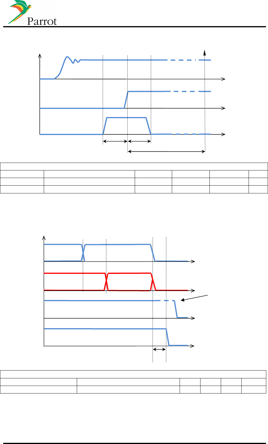
3.7 Flash update sequence diagram
Conditions unless noted, otherwise : Tamb.=25°C; Vc c=3V3
Parameter
Conditions
Min.
Typ.
Max.
Unit
tBS 30 - - µs
tBH 30 - - µs
3.8 Power Off Sequence diagram
Conditions unless noted, otherwise : Tamb.=25°C; Vc c=3V3
Parameter
Conditions
Min.
Typ.
Max.
Unit
tCut 0 10 - µs
RESET_EXT_N
tCUT
UART_AT_RX
AT*POFF
*POFF:END
UART_AT_TX
3V3
RESET_EXT_N pin
must be driven low
before next start-up
3V3
RESET_EXT_N
BOOTS
Flash Update
Complete
tBS
tBH
t
FL
DATASHEET FC6000 Confidential Information 21/53
3.9 Motherboard Electrical Integration
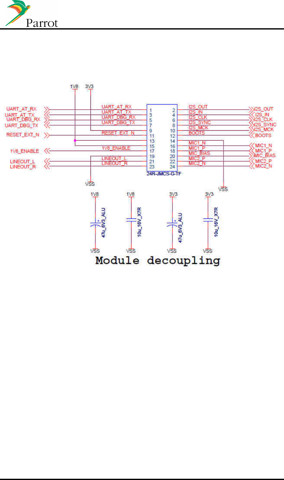
3.9.1 Connector
DATASHEET FC6000 Confidential Information 22/53
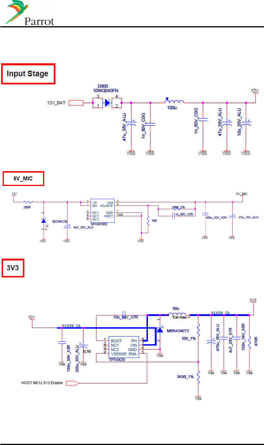
3.9.2 Power stage
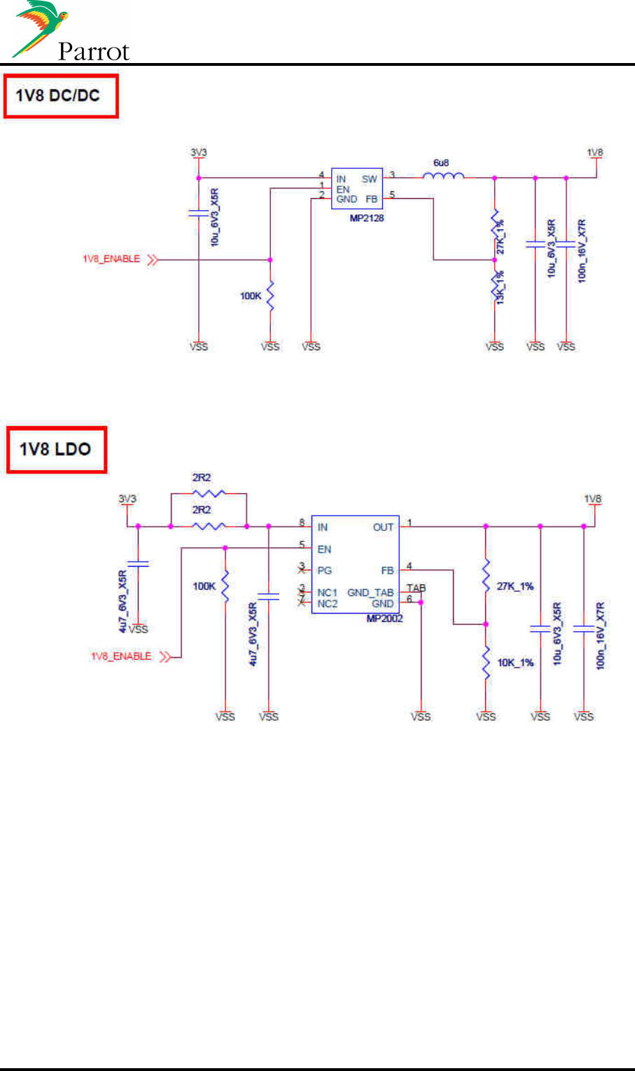
DATASHEET FC6000 Confidential Information 23/53
DATASHEET FC6000 Confidential Information 24/53
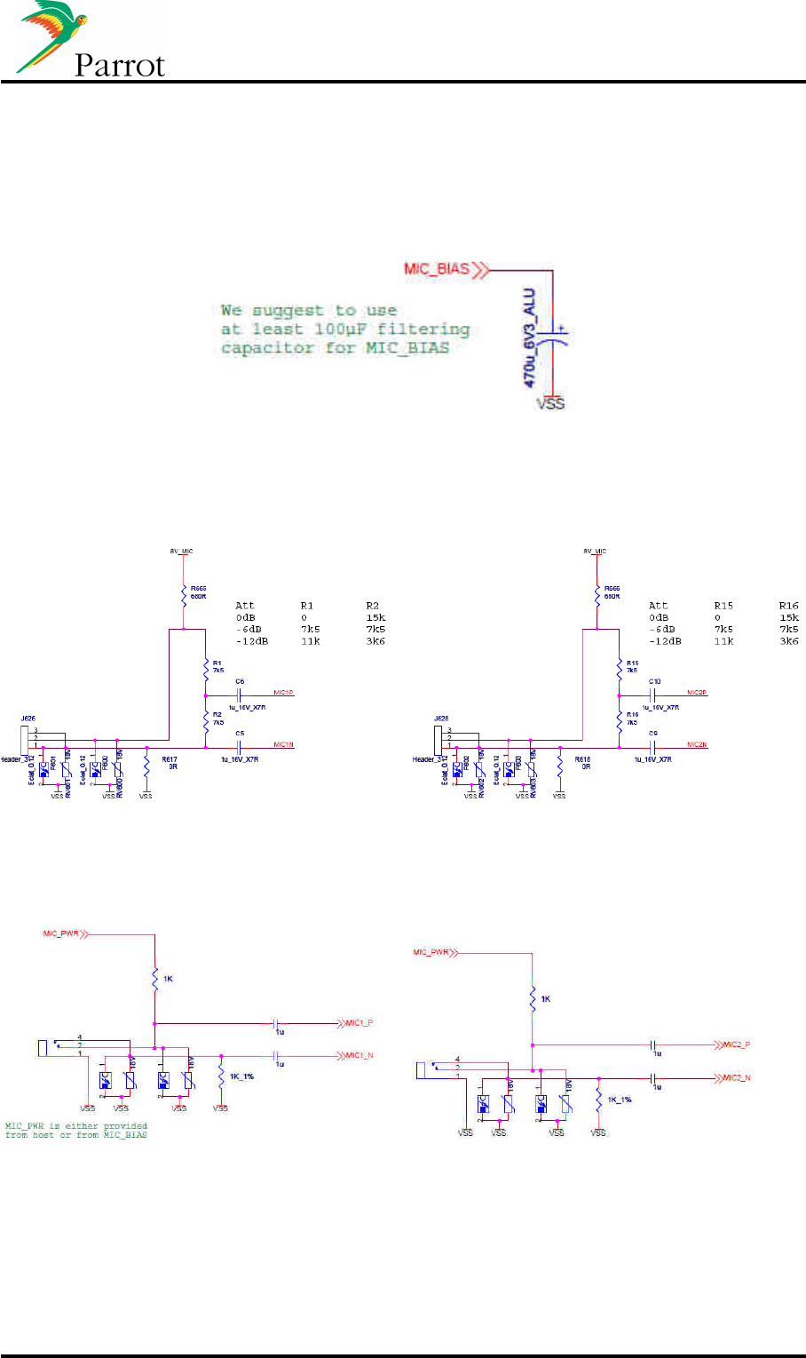
3.9.3 Microphone
3.9.3.1 Microphone bias filtering
3.9.3.2 Active microphones
3.9.3.3 Passive microphones
DATASHEET FC6000 Confidential Information 25/53
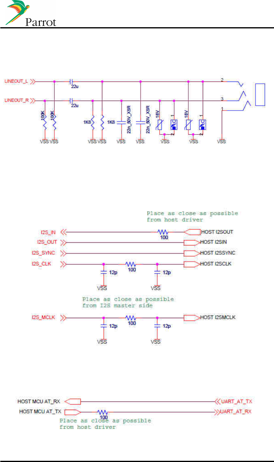
3.9.4 Line out
3.9.5 I2S
3.9.6 UARTs

DATASHEET FC6000 Confidential Information 26/53
3.9.7 Boots
3.9.8 Reset Pin

DATASHEET FC6000 Confidential Information 27/53
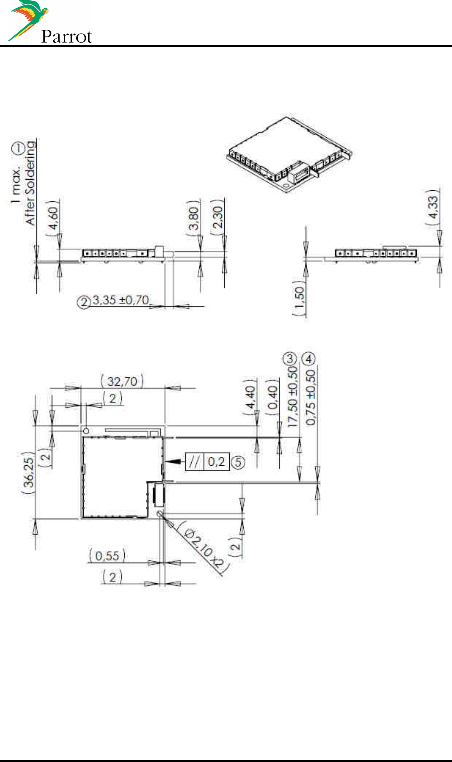
4 Mechanical specifications
The following chart describes the availability of the various versions of the FC6000.
Module version Mounting
Bluetooth antenna
Internal external
FC6000 horizontal
Yes Yes
vertical Yes Yes
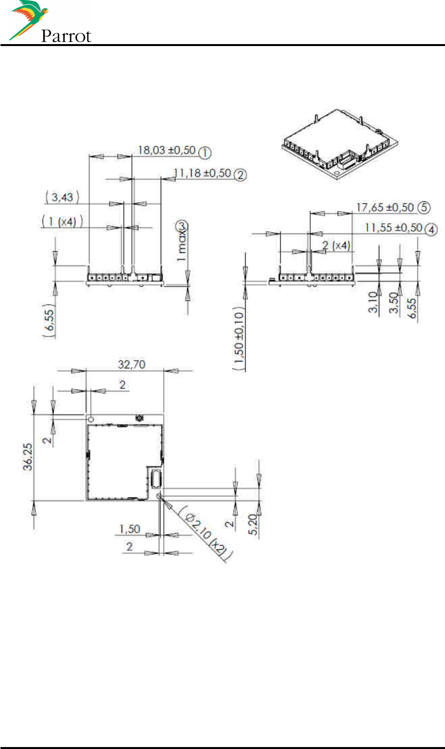
DATASHEET FC6000 Confidential Information 28/53
4.1 Horizontal module with external antenna
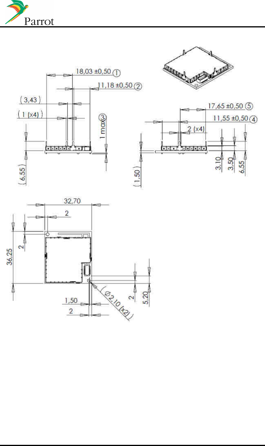
DATASHEET FC6000 Confidential Information 29/53
4.2 Horizontal module with internal antenna
DATASHEET FC6000 Confidential Information 30/53
4.3 Vertical module with external antenna
DATASHEET FC6000 Confidential Information 31/53
4.4 Vertical module with internal antenna
DATASHEET FC6000 Confidential Information 32/53
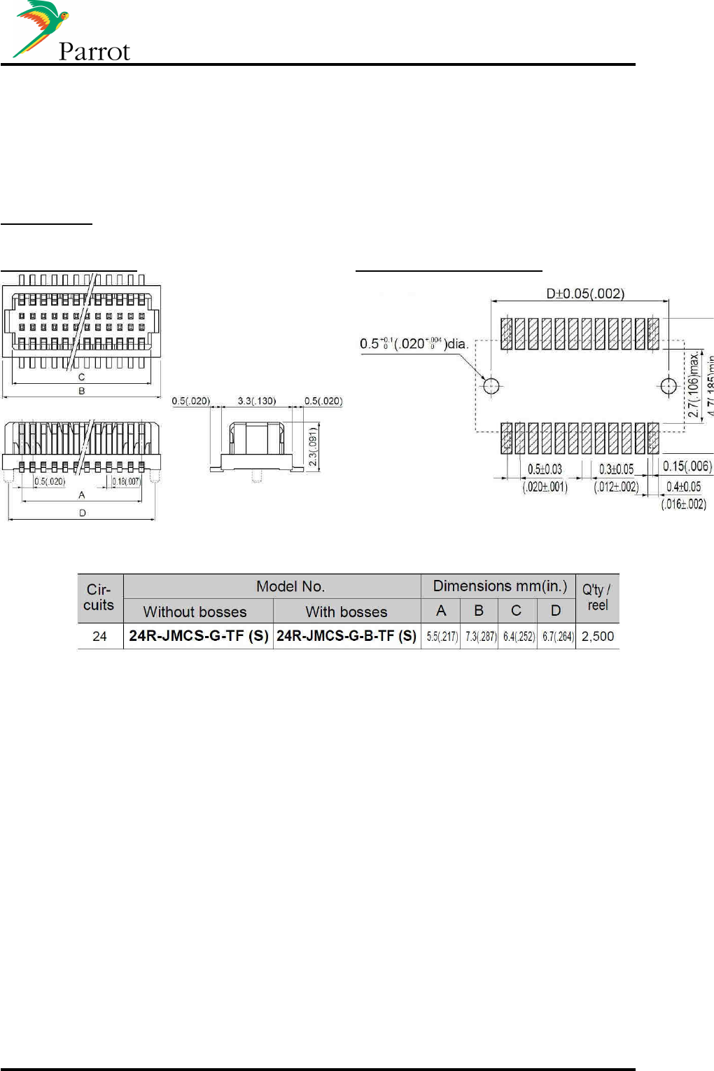
4.5 Module connectors
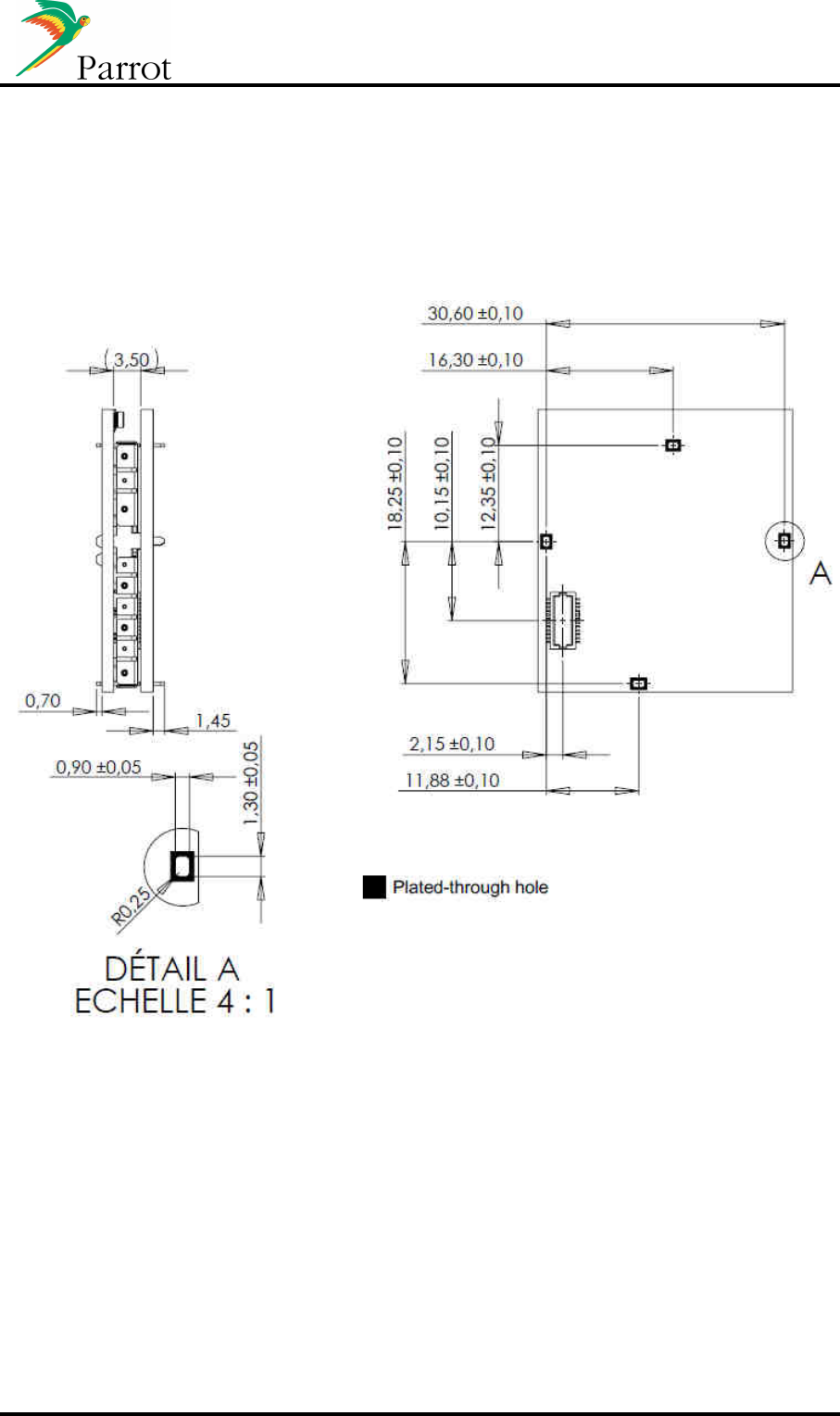
4.5.1 Connector on mother board
JST reference
:
24R-JMCS-G-(B)-TF
Mechanical overview: Recommended PCB footprint:
DATASHEET FC6000 Confidential Information 33/53
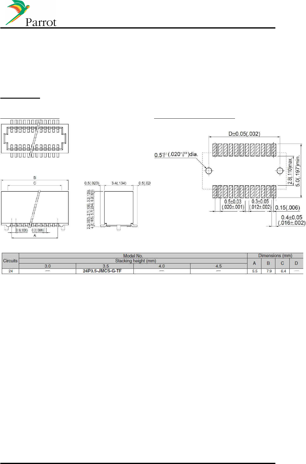
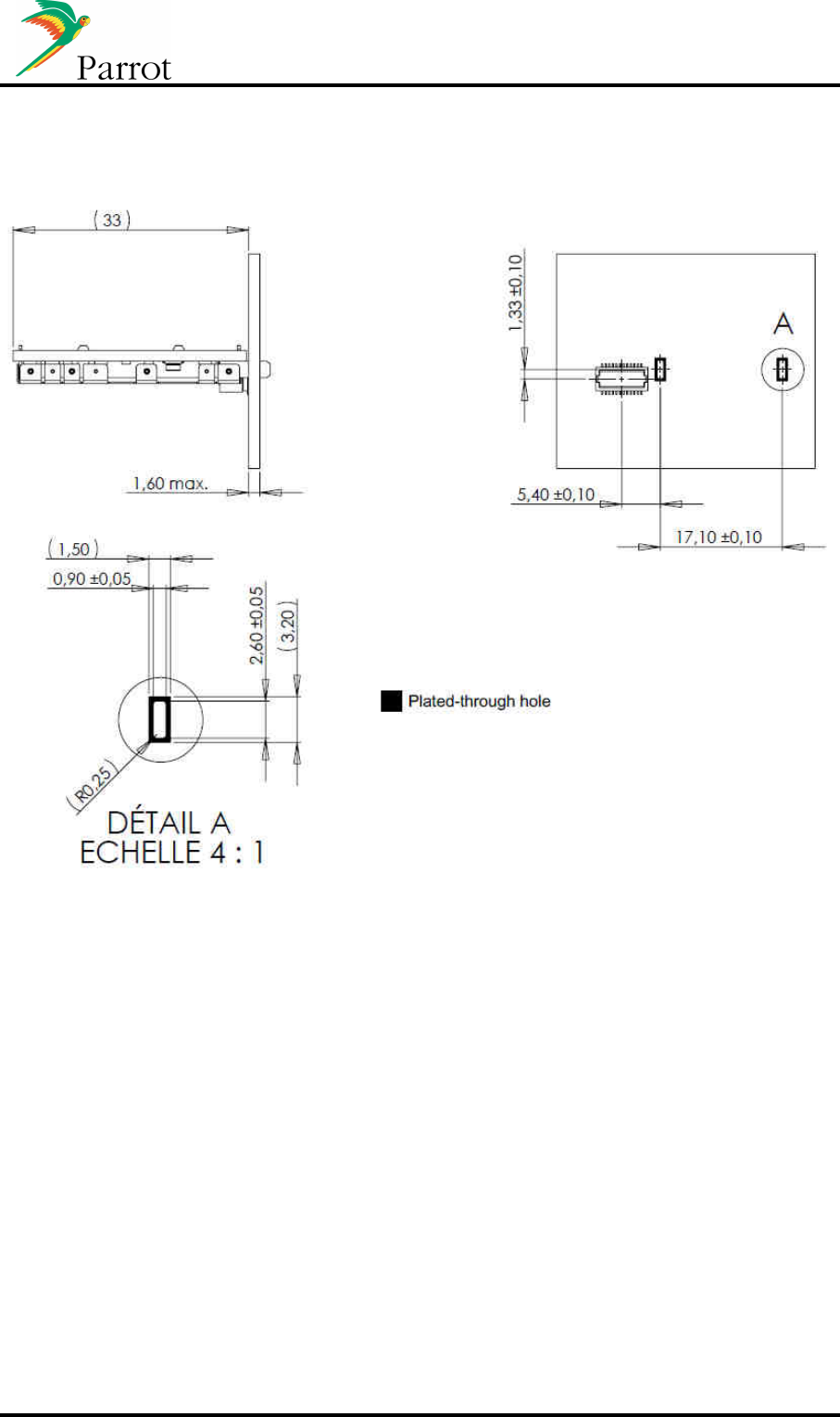
4.5.2 Horizontal modules connector
JST reference
:
24P3.5-JMCS-G-TF (Top entry type)
Mechanical overview: Recommended PCB footprint:
DATASHEET FC6000 Confidential Information 34/53
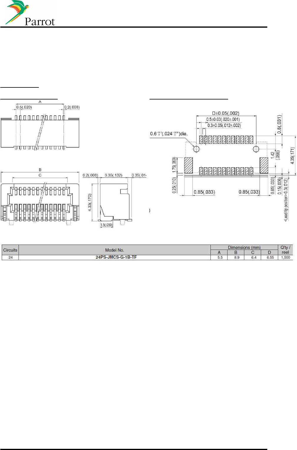
4.5.3 Vertical modules connector
JST reference
:
24PS-JMCS-G-1B-TF (Side entry type)
Mechanical overview: Recommended PCB footprint:
DATASHEET FC6000 Confidential Information 35/53
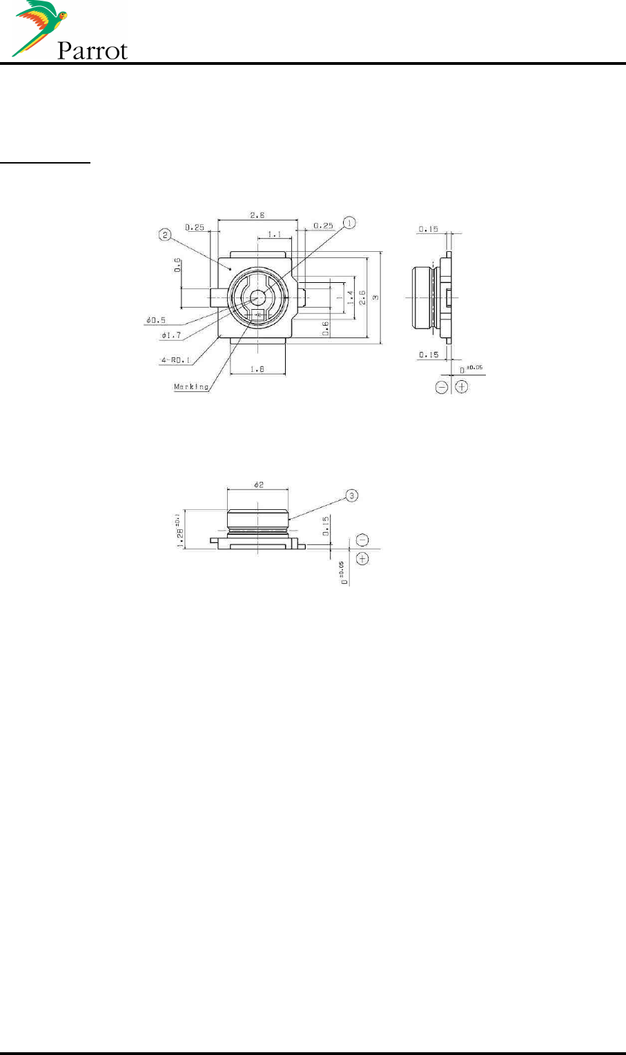
4.5.4 Antenna connector
JST reference
:
AYU1-1P-02676-120
DATASHEET FC6000 Confidential Information 36/53
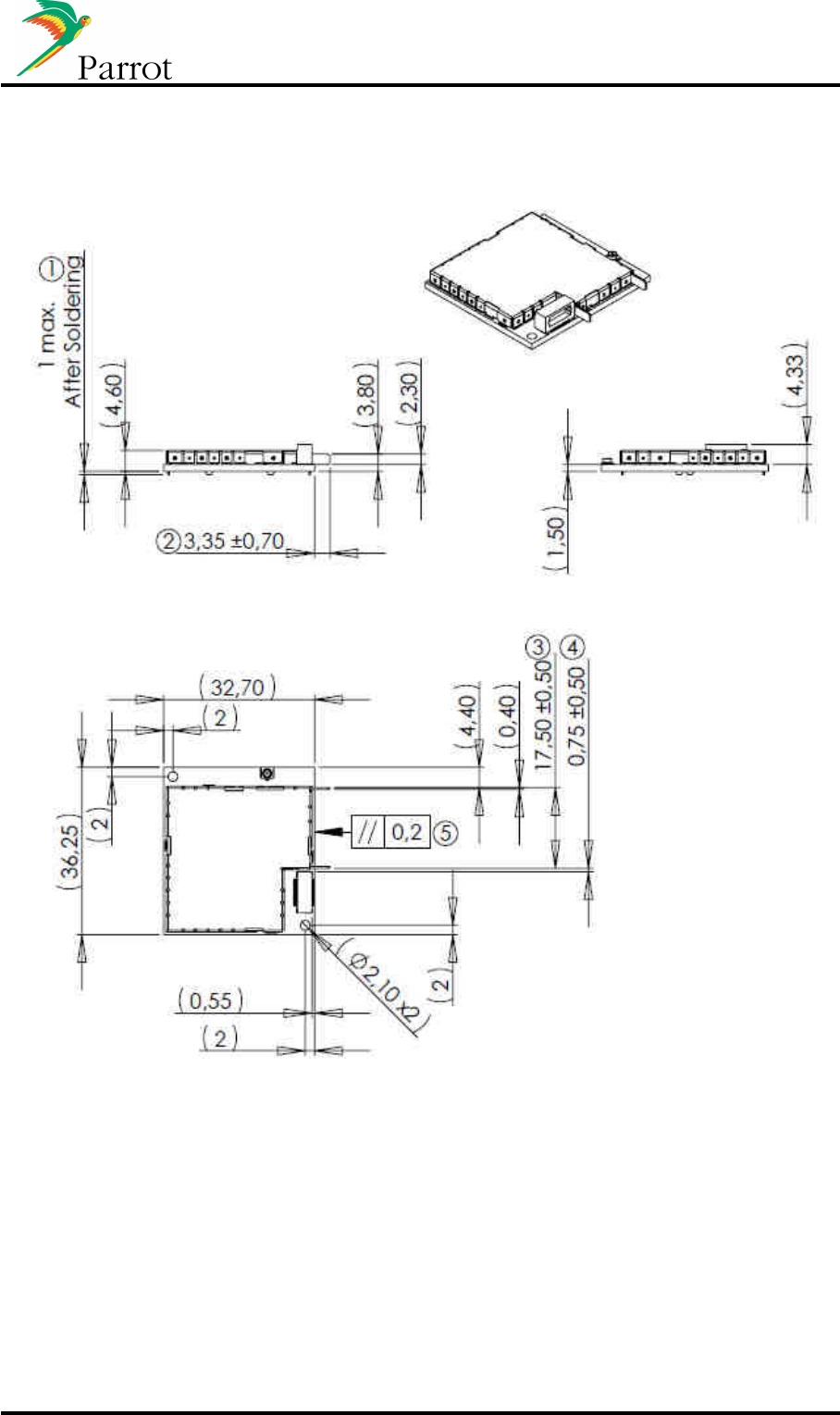
4.6 Motherboard Mechanical Integration
Mechanical constraints for the integration on the mother board are detailed below.
4.6.1 Mechanical integration – Horizontal version:
DATASHEET FC6000 Confidential Information 37/53
4.6.2 Mechanical integration – Vertical version:
DATASHEET FC6000 Confidential Information 38/53
5 Available tools
5.1 Workbench
5.1.1 Diagram

DATASHEET FC6000 Confidential Information 39/53
5.1.2 Schematics
The workbench schematic will be provided on demand
DATASHEET FC6000 Confidential Information 40/53
5.2 WxHipHop
WxHipHop is a windows based software that gives the possibility to send and read the AT commands
used by the FC6000.
5.3 WxFlasher
WxFlasher is a windows based software that gives the possibility to flash and to update the software
of the FC6000.

DATASHEET FC6000 Confidential Information 41/53
6 Approval / Certifications
6.1 CE Declaration
We, Parrot SA 174 quai de Jemmapes 75010 Paris France, declare under our responsibility that our
product (Parrot FC6000S) is in conformity with the Radio and Telecommunication Equipment
directive 1999/5/EC R&TTE according to the essentials requirements and respect the standard listed
below :
3.1-a) Electrical Safety EN60950-1:2006/A11:2009
EMF EN50371 (06/2002)
3.1-b) EMC EN301 489-1 V1.8.1
3.2 Radio EN300 328 V1.7.1
Paris, May 27th , 2011
Qualification Manager
Arezki Guerrab

DATASHEET FC6000 Confidential Information 42/53
6.2 FCC and IC requirements for module application
FCC ID: RKXFC6000S
IC : 5119A-FC6000S
In accordance with FCC Part 15, the FC6000S is listed as a Modular Transmitter device.
USA – User information
This intends to inform how to specify the FCC ID of our module “FC6000S” on the product. Based on
the Public Notice from FCC, the host device should have a label which indicates that it contains our
module. The label should use wording such as: “Contains FCC ID: RKXFC6000S”
Any similar wording that expresses the same meaning may be used.
The label of the host device should also include the below FCC Statement. When it is not possible,
this information should be included in the User Manual of the host device.
“This device complies with part 15 of the FCC rules. Operation is subject to the following two
conditions.
(1) This device may not cause harmful interference
(2) this device must accept any interference received, including interference that may cause
undesired operation.
Caution: Changes or modifications not expressly approved by the party responsible for compliance
could void the user’s authority to operate the equipment.
Canada – User information
This intends to inform how to specify the IC ID of our module “FC6000S” on the product. According
to Canadian standards “RSS 210” and “RSS Gen” , the host device should have a label which indicates
that it contains our module. The label should use wording such as: “Contains IC ID: 519A-FC6000S
Any similar wording that expresses the same meaning may be used.
The label of the host device should also include the below IC Statement.
When it is not possible, this information should be included in the User Manual of the host device.
“Operation is subject to the following two conditions:
(1) this device may not cause interference, and
(2) this device must accept any interference, including interference that may cause undesired
operation of the device.”
Le présent appareil est conforme aux CNR d'Industrie Canada applicables aux appareils radio
exempts de licence. L'exploitation est autorisée aux deux conditions suivantes :
(1) l'appareil ne doit pas produire de brouillage, et
(2) l'utilisateur de l'appareil doit accepter tout brouillage radioélectrique subi, même si le brouillage
est susceptible d'en compromettre le fonctionnement.

DATASHEET FC6000 Confidential Information 43/53
7 Use Cases
A. Bluetooth HFP & A2DP/AVRCP use cases overview:
a. Head Unit paired with Mobile phone
Handsfree telephony & Phonebook Synchronization
Hands Free Audio Gateway
Hands Free Device
Mobile Phone
Audio unit
Hands Free Telephony
Telephony
Phonebook
Phonebook synchro
FC6000
Connections Strategy
If the Host does not store the last synchronized phonebook, it is always available for the Host
at Module start up. Right after HFP connection (which is initiated to the last connected
device), it is possible to place an outgoing call if requested. Once HFP initialization has
finished (end of SLC/Extended SLC), the Module starts the best phonebook synchronization
method available on the phone. The Module alerts the Host that the updated phonebook with
new entries is available, and ready to be displayed on the HMI.
If an incoming/outgoing call occurs during the phonebook synchronization process,
depending on the method of phonebook synchronization which is used, the process is
paused. Once the call is finished, the phonebook synchronization restarts from where it has
been stopped, and the call history is updated. This is transparent for the end user.
Calls Management
For incoming calls, the Caller ID (received from phone via CLIP or CLCC) is sent to the Host
to be displayed on the HMI.
HFP indicators such as signal level, battery level and network provider are forwarded to the
Host to be displayed on the HMI. CIND/CIEV indicators or GSM AT Commands are used for
this purpose.
Service Continuity
This feature handles the audio management of a call when the module is powered on/off:
- When the module is powered on, the module automatically connects HFP to the
phone and establishes the communication ((e)SCO connection) through the speakers
during the SLC.
- When the module is powered off, the module transfers the audio to the phone
((e)SCO disconnection) and disconnects the Bluetooth link.
This process ensures the Host to be immediately ready to start Handsfree usage.

DATASHEET FC6000 Confidential Information 44/53
Three way calling / multiple calls management
Once a call is established, if a second incoming call occurs, here is how the Host should
handle the HMI:
- Green button: takes the second incoming call as active, and put the first one on hold.
Press green button again to switch between the two calls.
- Red button: hangs up the active call and takes the second one as active.
Full 3-way calling management (and multiparty calls) is optimized with phones supporting
HFP1.5. Parrot supports up to 7 calls at the same time for conference calls purpose.
With phones supporting HFP1.0 only, there are gaps in the specification such as:
- When the user manages the calls from the phone interface, the phone does not
always notify the Module.
- When the distant party who is on hold hangs up from its side.
DATASHEET FC6000 Confidential Information 45/53
b. Head Unit connected to Mobile phone and headset device
SCO link
Audio 8 kHz Mono
Car announcements
(Navigation,etc…)
and Communication privacy
Hands Free Audio Gateway
Hands Free Device
Hand Free Audio Gateway
Mobile Phone
Hands Free Telephony
Phonebook synch
ro
Telephony
Phonebook
Audio unit
FC6000
SCO forwarding feature (2 SCO)
The module is connected to a Headset and a phone at the same time. When requested by
the user, the Module is able to forward audio from the phone to the Headset. Therefore, the
communication is switched for privacy purpose. Two SCO channels are opened from the
Module.
Description of the behavior:
- Incoming call:
o Pick up from the HMI will pick up the call and establish one (e)SCO with the
phone and one with the Headset.
o Hang up from the HMI will hang up the call and release the 2nd SCO.
- Outgoing call:
o Dialing from the HMI will place the call on the phone, and once the remote
party has picked up, one (e)SCO is established with the phone and one with
the Headset.
o Hang up from the HMI will hang up the call and release the 2nd SCO.
A command is proposed on Parrot Module to handle the establishment of dual SCO,
depending on user need.
DATASHEET FC6000 Confidential Information 46/53
c. Head Unit paired with two Mobile phones
Establish and receiving call possible on two different mobile phones
Hands Free Audio Gateway
Hands Free Device
Mobile Phone
Hands Free Telephony
Telephony
Phonebook
Phonebook synchro
Mobile phone
Hands Free Audio Gateway
Audio unit
FC6000
Multi HFP Feature
Parrot has developed the “Multi - HFP”, which enables the Module to handle two Handsfree
connections at the same time. This use case is useful for people having two mobile phones,
or when two users are in the car.
The Module is running phonebook synchronization on both phones, and each phone has its
own phonebook available for the Host (phonebooks are not merged).
HFP indicators are available for each phone.
Description of the behaviour:
- First example: two phones (P1 and P2) are connected to HFP service. The host can
start dialing on P1, hang up call then start outgoing call on P2.
- Second example: the phone receives incoming call P1 on Module. After the end of
the first call from P1 the phone P2 can receive incoming call.
The multi HFP does not manage the calls of two phones at the same time.

DATASHEET FC6000 Confidential Information 47/53
d. Audio Streaming and Handsfree working together
Audio Streaming from phone to Module (remotely controlled by the Module)
A2DP source
A2DP Sink
Mobile Phone or
Music Player
MP3 or SBC (A2DP & AVRC)
44 kHz stereo
Streaming
Control
Audio unit
FC6000
AVHFP Feature
Most phones now support both HFP and A2DP Source/AVRCP TG. The most difficult case is
to correctly handle the AVHFP Feature (dual use of A2DP/AVRCP and HFP).
As there is no specification release by the Bluetooth SIG explaining how this multi-profile use
case should operate, a whitepaper has been issued by the A/V Working Group
(“Simultaneous Use of HFP, A2DP, And AVRCP Profiles”).
Basically, the Whitepaper states that the phone should handle the streaming restart
management once the call is finished (this is the main concern today):
- Incoming call: the AG should handle the streaming management:
o Pause the streaming on incoming call.
o Send to the HF the indicators (CIEV Call setup)
o Then the HF picks up the call with ATA, communication/SCO is established
o Once finished (from AG or HF), the AG should restart streaming from where it
has been paused.
- Outgoing call from HF (ATD): the AG should also handle this in the same manner.
Nevertheless, most phones do not correctly implement the Whitepaper, and the streaming
does not always restart after the call. Parrot has developed a strategy that automatically
relaunches streaming in this case.
Song information availability
According to the AVRCP version supported by the music player (can be a phone or a
Bluetooth Music player), the Host is updated with the following information in order to update
its HMI.
AVRCP TG 1.0 (Category 1 – Music Players):
- Mandatory commands:
o Play and stop.
- Optional Features:
o Enhanced control: Next, Previous, Pause, FF, FW (most of the
phones/Players supporting AVRCP1.0 support those commands).

DATASHEET FC6000 Confidential Information 48/53
o There are a lot of other features, but the phone/Bluetooth Music Players do
not implement these extended commands.
AVRCP CT 1.0 (Category 1 – Parrot Module):
- At least one command of the specification should be supported.
- Parrot has decided to implement the full Player Control (events send to the phone):
o Play, Pause, Stop, Next, Previous, Pause, FF, FW
AVRCP TG 1.3 (Category 1 – Music Players):
- Mandatory commands:
o Same perimeter as AVRCP TG 1.0.
- Optional Features:
o If the phone supports the Bluetooth SIG Vendor Unique Feature, only Title of
the Media is mandatory for Metadata. And Playback status and change of
current track shall be supported in this case.
o Other important features for Metadata support are Name of the Artist, Name
of the Album, Genre...
AVRCP CT 1.3 (Category 2 – Parrot Module):
- Mandatory commands:
o Same perimeter as AVRCP CT 1.0.
- Parrot optional features implemented:
o Referring to the specification, all “List of Media Attributes” are supported to be
displayed on the car radio HMI.
AVRCP TG 1.4 (Category 1 – Music Players)
5
:
- Mandatory commands:
o Same perimeter as AVRCP TG 1.0.
- Optional Features:
o If the phone supports the Bluetooth SIG Vendor Unique Feature, only Title of
the Media is mandatory for Metadata. And Playback status and change of
current track shall be supported in this case.
o Other important features for Metadata support are Name of the Artist, Name
of the Album, Genre...
AVRCP CT 1.4 (Category 2 – Parrot Module)
6
:
- Mandatory commands:
o Same perimeter as AVRCP CT 1.0.
- Parrot optional features implemented:
o Referring to the specification, all “List of Media Attributes” are supported to be
displayed on the car radio HMI.
According to the AVRCP version supported by the phone, the HMI should be implemented
with information provided by the Module: Player status / Metadata for the current played
song.
As member of AV Working Group, Parrot is involved with the development of those
specifications.
5
For NAND version Only
6
For NAND version Only
DATASHEET FC6000 Confidential Information 49/53
e. Head Unit paired with Mobile phone and Music Player with BT
integrated or Bluetooth dongle:
A2DP Source
A2DP Sink
Mobile Phone or
Music Player
MP3 or SBC (A2DP & AVRC
P
)
44
,1
kHz stereo
Streaming
Control
Mobile phone
Audio unit
FC6000
Connection Management
Parrot Module is able to maintain two Bluetooth connections: one HFP to a phone (where the
phonebook synchronization is running after connection) and the other one with an A2DP
SRC Music Player. From the Module point of view, there are two users connected.
As stated with the Whitepaper, in this use case, the Module handles the AVHFP because the
A2DP SRC is not the connected phone. If the Bluetooth Music Player supports AVRCP TG,
Parrot alerts the HMI with Playback status and Metadata.

DATASHEET FC6000 Confidential Information 50/53
f. Head Unit paired with a stereo Headphone
Audio Streaming from Module to a stereo headphone
A2DP Sink
A2DP Source
Bluetooth
Headphones
MP3 or SBC (A2DP & AVRC
P
)
44,1 kHz stereo
Streaming
Control
Audio unit
FC6000
Parrot Module also embeds the A2DP SRC role, and then is able to play local music files to a
Sink device.

DATASHEET FC6000 Confidential Information 51/53
g. Head Unit paired with Mobile phone: Data transfer
Dial Up Networking: The Head Unit acts as data terminal with a connected gateway device,
typically a mobile phone.
DUN
Gateway
Data Terminal
Device
Mobile Phone
Data exchange
Data flow
Audio unit
FC6000
Multi Profile Use
Parrot handles multiple Bluetooth connections. On the same device, it is possible to set up
both an HFP and a DUN connection.
According to the various Bluetooth implementations on phones, here is the description of
what is possible (given no phone limitations):
- DUN only:
o In this case, the phone acts as a Gateway and the Module forwards the data
to the Host (Data Terminal).
- HFP and DUN:
o If an incoming call occurs during the data transfer, there are three behaviors:
The call is established and data transfer continues without bandwidth
diminution.
The call is established and data transfer is stopped (AG gives priority
to HFP feature).
The distant caller reaches the voice mail of the connected phone
(phone limitation).
o If an outgoing call is requested by the user, the behaviors above also apply.
Those behaviors are described, phone by phone in the Parrot Bluetooth Compatibility Matrix
with all tested phones.
DATASHEET FC6000 Confidential Information 52/53
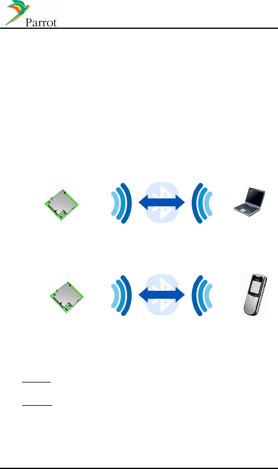
B. Head unit BT/UART software update
The firmware of Parrot modules can be updated in two different ways: by Bluetooth when
paired with
a
Bluetooth-enabled laptop
, or UART.
This is a very important feature of the Parrot Module. This ensures better Bluetooth
Compatibility with new phones coming on the Market. Some of these new phones need to
have a specific workaround when the Bluetooth specifications are not correctly implemented
on the phone (i.e. non-generic Bluetooth management).
Moreover, a major software update can include a new feature/profile (such as AVRCP1.4 for
instance) to give more compatibility or functionality to a car radio. This software update can
immediately be flashed (by Bluetooth, Uart...) into your product already out in the market.
After the update, user settings (paired devices, phonebooks...) are not erased. This process
is transparent for the user.
Hands Free
update
Hands Free Device
Computer
Update by Bluetooth or UART
D
ata flow
Audio unit
FC6000
DUN
Gateway
Data Terminal
Device
Mobile Phone
Data flow
Update by B
luetooth
Audio unit
FC6000
Methods available
- Bluetooth
o Via SPP
o Via FTP
- Via UART with a host CPU that send the data

DATASHEET FC6000 Confidential Information 53/53
Secured update mechanism
The new software is copied into the flash Module’s memory but the previous software is not
affected by this copy. During this process, if an error occurs before the end of file transfer
(Bluetooth disconnection, data transfer stopped,…), the module will restart with the previous
software version.
The checksum of the new software is included into this new software. If the new file is
correctly written into the flash, when Module will reboots, the new checksum internally
calculated is compared the checksum of this new software. If checksum are equals, the new
file will overwrite the previous one. During this process, if power supply is turned off, the
remaining data will be continuing to be written where it has been stopped at the next boot.