PARROT FC6050W Bluetooth Module User Manual FC6050 Datasheet V1 68
PARROT Bluetooth Module FC6050 Datasheet V1 68
PARROT >
user manual

PARROT PRODUCT DATASHEET
Parrot
FC6050
FC6050B and FC6050W
Version 1.67
August 2011
Confidential information
DATASHEET Confidential Information 2/84
Ref:
EL
-
2009
-
009
Parrot FC6050B
Full connectivity platform
Bluetooth 3.0
FEATURES
Bluetooth 3.0 qualified module
IPod chip management,
SD card management
Piconet and scatternet support
Standard single 3.3V supply
UARTs, I²C,
USB 2.0 High Speed,
Digital audio input and output
Analog audio input and output
Module dimension 34.5 x 41.35 mm x
4.60mm
Automotive qualified.
Application:
• Telephony
• Bluetooth 3.0
• Audio streaming
• USB, SD
• IPod management
The FC6050B includes the latest version
of the Parrot Bluetooth software stack
(Blues). Blues provides a very high level of
compatibility with most of the phones
available on the market today. It also
provides phonebook and call list
synchronization.
The FC6050B also includes Concertos, a
Parrot proprietary database management
library used for the management of audio
files. Concertos facilitates management of
audio from all available storage media
such as USB/IPOD, SD, PHONE/A2DP.
Concertos manages the media devices,
builds a database with metadata, browses
the compressed audio files by
artist/genre/title and plays them. FC6050
offers the possibility to use a Speaker
Independent Voice Recognition (SIVR)
and a Text To Speech algorithm
(TTS).The FC6050B software is built upon
the Linux operating system. The library
RAP gives the possibility to recognize
song titles or artist name
Description:
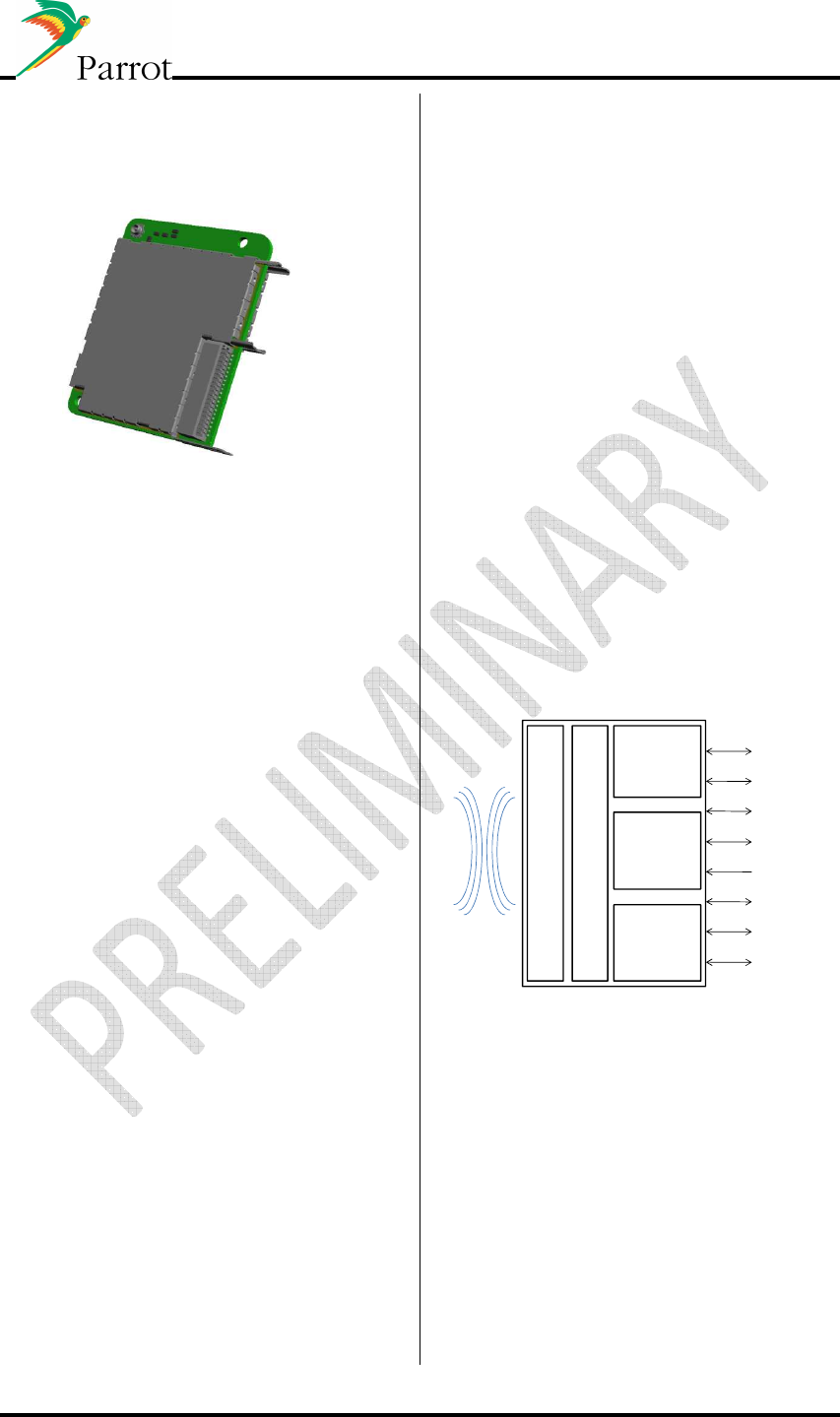
The Parrot FC6050B is a complete
connectivity solution. It offers a large
variety of interfaces for easy integration in
most applications.
Parrot
P6i
FLASH
SDRAM
2*UART
1*I²C
2*I²S out/ 2*I²S in
2*Analog microphone input
1*Stereo Analog line in
BT3.0
1*USB 2.0 High Speed
SD card
Bluetooth Antenna
1*Stereo Analog line out
DATASHEET Confidential Information 3/84
Ref:
EL
-
2009
-
009
Parrot FC6050W
Full connectivity platform
Bluetooth 3.0+HS,
Wi-Fi (802.11 b/g/i)
FEATURES
Bluetooth 3.0+HS qualified module
IPod chip management, Wi-Fi b/g/i/j
Piconet and scatternet support
Standard single 3V3 supply
UARTs, I²C,
USB 2.0 High Speed,
Digital audio input and output
Analog audio input and output
Module dimension 34.5 x 41.35 mm x
4.60mm
Automotive qualified.
Application:
• Telephony
• Wi-Fi
• Bluetooth 3.0+HS
• Audio streaming
• USB
• IPod management
• UPNP server synchronization
In addition to the features supported by
the FC6050B, the FC6050W supports also
WiFi connections (ad Hoc, station, AP)
and Bluetooth 3.0 + HS.
Description:
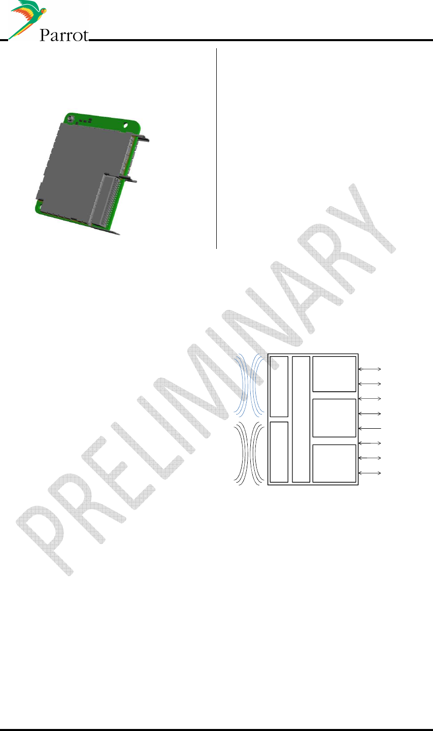
The Parrot FC6050W is a complete
connectivity solution. It offers a large
variety of interfaces for easy integration in
most applications.
Parrot
P6i
FLASH
SDRAM
2*UART
1*I²C
2*I²S out/ 2*I²S in
2*Analog microphone input
1*Stereo Analog line in
WIFI/BT3.0+HS
1*USB 2.0 High Speed
3*GPIO
Wi-Fi Antenna
Bluetooth
Antenna
1*Stereo Analog line out

DATASHEET Confidential Information 4/84
Ref:
EL
-
2009
-
009
Table of contents
1
Product overview ............................................................................................................................ 7
1.1
FC6050B/W features: .............................................................................................................. 7
2
Software specifications ................................................................................................................. 10
2.1
Bluetooth stack...................................................................................................................... 10
2.2
Bluetooth profile supported.................................................................................................. 10
2.3
FC6050W Wi-Fi summary...................................................................................................... 11
3
Bluetooth 3.0+HS use cases (FC6050W) ....................................................................................... 11
4
USB Hub......................................................................................................................................... 11
5
Wi-Fi features and main scenarios (FC6050W) ............................................................................. 12
5.1
Share internet connectivity (AP) ........................................................................................... 12
5.2
Bluetooth High Speed (AP and client) ................................................................................... 12
5.3
Universal Plug and play (AP and client)................................................................................. 13
5.4
Wi-Fi tethering (client) .......................................................................................................... 13
6
Internet connectivity solutions ..................................................................................................... 14
6.1
Internet sources - Overview .................................................................................................. 14
6.2
Parrot router: ........................................................................................................................ 15
6.3
Miscellaneous........................................................................................................................ 15
7
Host to FC6050B/W interface details............................................................................................ 16
7.1
UART...................................................................................................................................... 16
7.2
Protocols used....................................................................................................................... 17
7.3
Standard networking over USB protocol for data transmission ........................................... 17
8
Software interface, HSTI Library.................................................................................................... 17
8.1
Parrot’s HSTI protocol for network connectivity................................................................... 18
9
Memory configurations................................................................................................................. 20
10
Speaker Independent Voice Recognition and Text to Speech ...................................................... 21
10.1
Voice Recognition principles ................................................................................................. 21
10.2
Text To Speech (TTS) ............................................................................................................. 21
10.3
Voice Recognition for Phonebook Access ............................................................................. 22
10.4
Voice Recognition for Music Data on external sources......................................................... 22
10.4.1
RAP ................................................................................................................................ 22
10.4.2
Gracenote® for Music Data on external sources........................................................... 22
10.4.3
Natural Language Understanding (NLU) ....................................................................... 23
10.5
Remote speech to text engine .............................................................................................. 24
11
Electrical specifications ................................................................................................................. 25
11.1
Hardware architecture FC6050B ........................................................................................... 25
11.2
Hardware architecture FC6050W.......................................................................................... 26
11.3
Pinout (FC6050W and FC6050B) ........................................................................................... 27
11.3.1
Pinout table 40 pins version .......................................................................................... 27
11.3.2
FC6050W Pinout table................................................................................................... 28
12
Electrical specifications ................................................................................................................. 30
12.1
Absolute maximum ratings ................................................................................................... 30
12.2
Power Supply......................................................................................................................... 30
12.2.1
Power Pin....................................................................................................................... 30
12.2.2
Power consumption ...................................................................................................... 30
12.3
Reset pin................................................................................................................................ 31
12.4
Firmware Update................................................................................................................... 31
12.5
GPIOs ..................................................................................................................................... 32
12.6
UART...................................................................................................................................... 32
12.7
I2C.......................................................................................................................................... 33
12.8
Audio ..................................................................................................................................... 34

DATASHEET Confidential Information 5/84
Ref:
EL
-
2009
-
009
12.8.1
Analog out ..................................................................................................................... 34
12.8.2
Analog in........................................................................................................................ 34
12.8.3
Microphone input.......................................................................................................... 34
12.9
I2S .......................................................................................................................................... 35
12.10
SDIO ................................................................................................................................... 37
12.11
USB .................................................................................................................................... 38
12.12
Wifi .................................................................................................................................... 39
12.13
Bluetooth........................................................................................................................... 41
12.14
Recommended external components schematics ............................................................ 42
12.14.1
Analog out ................................................................................................................. 42
12.14.2
Analog in.................................................................................................................... 42
12.14.3
Microphone input...................................................................................................... 43
12.14.4
USB ............................................................................................................................ 45
12.14.5
Supply FC6050B/W version ....................................................................................... 46
13
Mechanical specifications ............................................................................................................. 47
13.1
FC6050W Horizontal version................................................................................................. 48
........................................................................................................................................................... 48
13.2
PCB footprint for FC6050W horizontal module .................................................................... 49
13.3
PCB footprint for FC6050W vertical module......................................................................... 50
13.4
FC6050B PCB ......................................................................................................................... 51
13.5
PCB footprint for FC6050B horizontal module...................................................................... 52
13.6
PCB footprint for FC6050B vertical module .......................................................................... 53
13.7
Connectors specifications (FC6050 B/W) .............................................................................. 54
13.7.1
Vertical connector specification.................................................................................... 54
13.7.2
Horizontal connector specification ............................................................................... 55
13.7.3
Host connectors specification ....................................................................................... 55
14
Connectivity use cases overview................................................................................................... 56
14.1
Phone use cases .................................................................................................................... 56
14.1.1
Head Unit (FC6050B/W) paired with Mobile phone ..................................................... 56
14.1.2
Head Unit (FC6050B/W) simultaneously connected to Mobile phone and headset
device ....................................................................................................................................... 58
14.1.3
Head Unit paired with two Mobile phones................................................................... 59
14.1.4
Audio Streaming and Handsfree working together ...................................................... 60
14.1.5
Head Unit (FC6050 B/W) paired with Mobile phone and Music Player with Bluetooth
dongle: ....................................................................................................................................... 62
14.1.6
Head Unit paired with a stereo Headphone ................................................................. 63
14.1.7
Head Unit paired with two stereo Headphones............................................................ 63
14.1.8
Head Unit (FC6050 B/W) paired with Mobile phone: Data transfer............................. 64
14.2
USB/iPod Use Cases............................................................................................................... 65
14.2.1
Head Unit (FC6050 B/W) with an iPod connected through the USB............................. 65
14.2.2
IPod & iPhone use cases................................................................................................ 66
14.2.3
Head Unit (FC6050B/W) paired with a connected USB Mass storage device............... 67
14.3
Head unit (FC6050 B/W) BT/USB/Wi-Fi software update..................................................... 68
14.4
Wi-Fi use cases ...................................................................................................................... 70
14.4.1
Wi-Fi access point.......................................................................................................... 70
14.4.2
Wi-Fi station .................................................................................................................. 72
14.4.3
Internet access with mobile phone tethering ............................................................... 73
14.4.4
DLNA and UPNP............................................................................................................. 74
14.4.5
Future use cases ............................................................................................................ 75
15
Workbench .................................................................................................................................... 77
15.1
Bloc Diagram.......................................................................................................................... 77
15.2
Connection & Jumpers Settings ............................................................................................ 78
16
Interoperability management during mass production................................................................ 79

DATASHEET Confidential Information 6/84
Ref:
EL
-
2009
-
009
16.1
Blues interoperability testing (compatible phones).............................................................. 79
16.2
Pilot phone testing of the gateway (Final product)............................................................... 80
17
Approval / Certifications ............................................................................................................... 82
17.1
Bluetooth 3.0+HS qualification.............................................................................................. 82
17.2
Wi-Fi qualification ................................................................................................................. 82
17.3
EMC certification................................................................................................................... 82
17.4
RoHS declaration. .................................................................................................................. 82
18
Communicate with FC6050 from PC: WxHipHop.......................................................................... 83
19
FCC and IC Requirements for module application ........................................................................ 84
DATASHEET Confidential Information 7/84
Ref:
EL
-
2009
-
009
1 Product overview
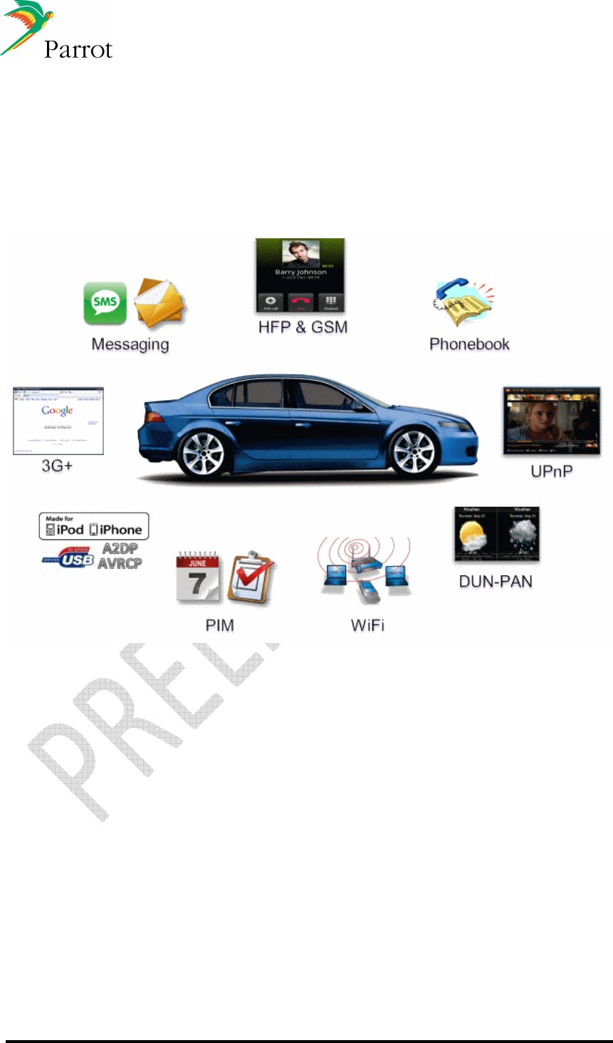
The FC6050 is a full connectivity platform designed to ease the integration of
connectivity applications in car audio systems, car telematics systems or any system
requiring a complete embedded connectivity solution.
1.1
FC6050B/W features:
• Bluetooth connectivity
Bluetooth Power Class 2 Radio
Embedded Bluetooth V3.0+HS (FC6050W only)
Multiple profiles running in parallel.
Pairing and connection with all Bluetooth Devices: Phones, Smartphones,
PDA, etc. Multiple user support: Up to 15 paired phones
• Wi-Fi (FC6050W)
IEEE 802.11b/g/i compliant (n compliant from 2012)
Data rates of 1–54 Mbps for 802.11g (270 Mbps starting 2012)
Security support for WPS, WPA2, WPA
Ad hoc, station, or Access Point mode
Up to 8 devices can simultaneously be connected in AP mode.
• SD card management (FC6050B)
• Full internet access
Internet Access via Wi-Fi (FC6050W only) or HSDPA using USB Dongle or
modules or Bluetooth
• UPNP server access over Wi-Fi. (FC6050W)

DATASHEET Confidential Information 8/84
Ref:
EL
-
2009
-
009
Personal files (music, pictures, etc ) can be downloaded from personal server
at home to the car
Browsing, Streaming and download interfaces
• Phone
Pick-up, Hang-up, Redial
Automatic answer (from host via dial command)
Send DTMF during calls
Private Mode
Multiparty call
• Phone Book
Automatic Phone book synchronization over Bluetooth (up to 15 paired
phones, more than 10,000 contacts per phone, depending on memory
available)
Call history (dialed number, received calls, missed calls)
All Synchronization Methods Supported
Specific behaviors applied for the best possible interoperability
Full Unicode for compatibility with numerous characters sets (European,
Russian, Chinese, Japanese…)
• Digital Signal Processing
Microphone(s): the module can manage two configurations:
Single microphone
Two microphones with AMS (Automatic Microphone Selection): 1 for
the driver and 1 for the front seat passenger. The best microphone is
automatically selected during the call.
Noise Reduction (NR)
Maximal NR is 25dB.
Typical NR is 15dB.
No musical noise
No fluctuation of the residual noise level
Automatic adaptation of the Noise Reduction to the Signal-to-noise
ratio (SNR) to keep the best voice quality in idle and remove more
noise in noisy conditions.
Acoustic Echo Cancellation (AEC)
The level of echo attenuation, called ERLE is 45dB (measured
according to the VDA process).
Comfort Noise feature so that the background noise is adjusted after
AEC algorithm, in order to keep it constant for enhanced
communication experience.
Possibility to accept up to 100ms of delay in the speaker path for digital
amplifiers.
Full duplex
Automatic Level Control (ALC)
Different phones can have different Speaker volumes (up to 20dB of
difference). It adapts the signal level received from the phone to the
target level, quickly and precisely.
Equalizer
9 bands equalizer for microphones and speaker paths.
Tuning
Car independent tuning if the microphone position and specifications
are the same.
Possibility to tune all parameters of the audio algorithms according to
Customer preferences.
Wideband speech (from 2012)
Support of HFP 1.6
All speech processing algorithms will work @ 16 kHz.
DATASHEET Confidential Information 9/84
Ref:
EL
-
2009
-
009
• Audio Streaming
Embedded SBC decoder
Embedded MP3 decoder from Thomson Licensing (optional)
Embedded AAC decoder from Via Licensing (optional)
Stereo audio output
• Concertos
Concertos is a software Library which acts as a multi-source media player.
Concertos enables DISCO playlist browsing on USB, iPod, SD and AVRCP1.4
devices
• Speaker Independent Voice Recognition (SIVR)
• Miscellaneous
Provides Phone Battery Level, Network Signal Level and Carrier Name
(depends on phone) to host
Embedded test pattern (test commands)
• Software Update
Full standard software available (free upgrade from Parrot homepage)
Software can be updated via Bluetooth, USB, UART
Software updates provide long term compatibility with latest Phones,
Smartphones, PDAs and Music players
• External Bluetooth Antenna diagnostic
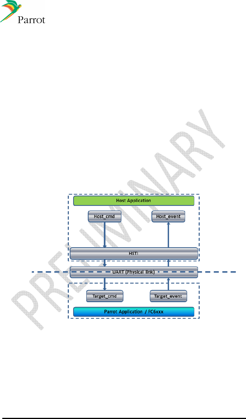
• HSTI
Parrot provides a library called “HSTI” that facilitates the integration and
communication with FC6050 (see §8).
Communication between the host and the FC6050 over UART

DATASHEET Confidential Information 10/84
Ref:
EL
-
2009
-
009
2 Software specifications
2.1
Bluetooth stack
• HCI (Host Controller interface),
• L2CAP (Logical Link Control and Adaptation Protocol),
• RFCOMM
• SDP (Service Discovery Protocol),
• OBEX (IrDA Object Exchange).
• Channel manager, AMP Manager, HCI AMP (BT 3.0+HS software).
2.2
Bluetooth profile supported
• Generic Access Profile
• Phone Management
HFP 0.96 - 1.0 - 1.5
HSP 1.0
SAP (SIM Access Profile, optional)
• Message Management
MAP 1.0
• Phone Book
PBAP 1.0
SYNC 1.1 (IrMC SYNC over BT)
SYNCML
OPP 1.0 Server/Client (Vcard 3.0)
GSM 07.07 AT Commands
Nokia synchronization protocol (MBUS)
• Multimedia
A2DP (Audio)
SBC decoding
(optional MP3 decoding)
AVDTP
AVRCP1.0 / AVRCP1.3 / AVRCP1.4
• Internet connectivity
DUN 1.1
BNEP, PAN
• Others
SPP 1.1
BIP
SDP
FTP 1.0
Image transfer over OPP
Software update over SPP
Remote configuration

DATASHEET Confidential Information 11/84
Ref:
EL
-
2009
-
009
2.3
FC6050W Wi-Fi summary
802.11b - 2.4GHz WiFi 11Mbps
Yes
802.11d - "World Mode"
No
802.11g - 2.4GHz WiFi 54Mbps
Yes
802.11h - 5GHz interferrence avoid
No
802.11i - Security
Yes
802.11j - Japan Standard
No
802.11n - 2.4GHz WiFi 150Mbps
Yes(1)
802.11y - High Power WiFi
No
Access Point support
on reset -frimware change
Ad-Hoc
Yes
Client
Yes
PAN - like Intel Cliffside multi point access
No
WPA2 / WPA
Yes
WAPI (China)
Yes(2)
2.4GHz
Supported
Coexistence
(1): FC6050 will be capable from 2012:
• Support Wi-Fi 802.11n: Higher throughput in preparation for LTE and longer range for
additional use cases.
• Ability to assist in beam forming from the external hotspot
• Supporting simultaneous AP and STA
(2) Available from 2012
3 Bluetooth 3.0+HS use cases (FC6050W)
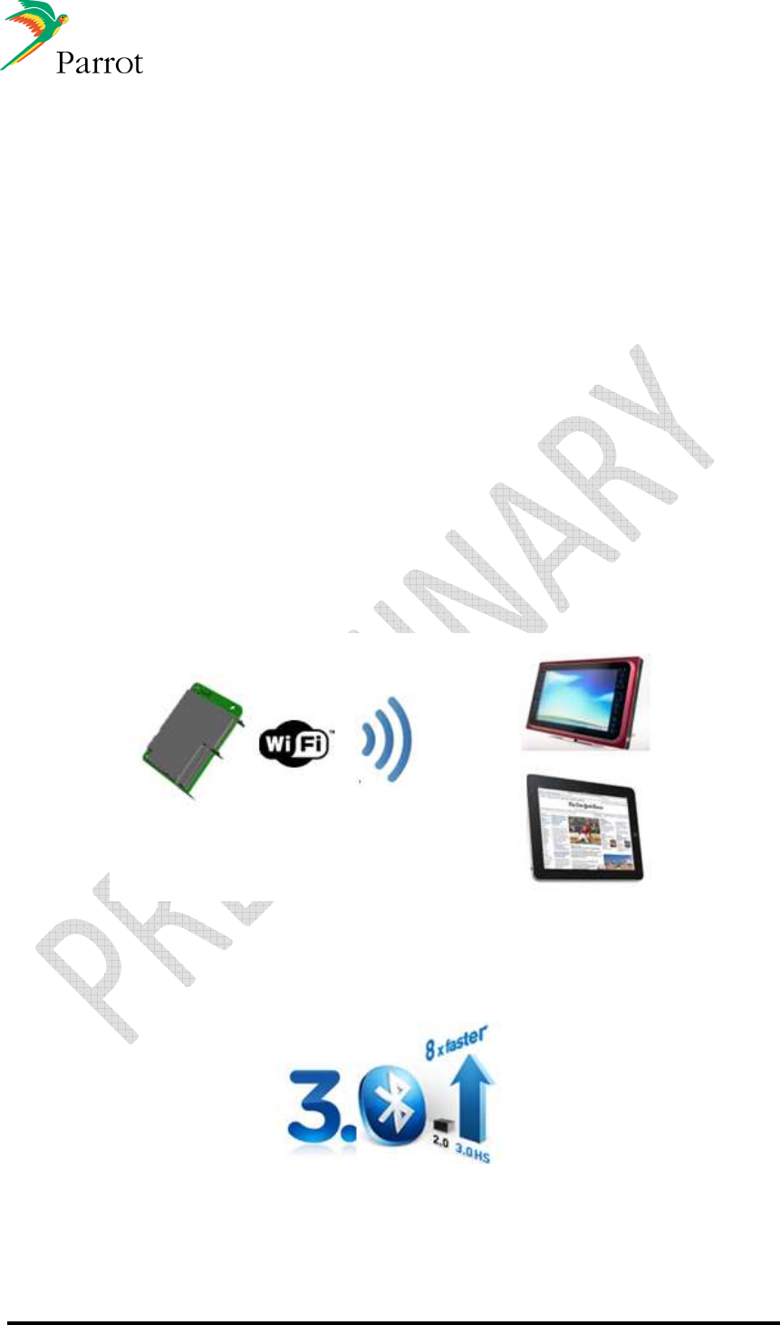
BT3.0+HS speeds-up Bluetooth profiles (~8 times faster)
• OPP (phonebook), FTP (transfer) and BIP (pictures) profiles already available.
• PBAP (phonebook) and MAP (messaging) will be available from 2012.
4 USB Hub
The FC6050W and FC6050B have one USB port
It is mandatory to use a USB hub external to the module if more than one USB device is
connected to the FC6050B/W
DATASHEET Confidential Information 12/84
Ref:
EL
-
2009
-
009
5 Wi-Fi features and main scenarios (FC6050W)
The Parrot module can either be configured as a Wi-Fi Access Point (AP), a Wi-Fi
station (client) or can be used in ad-hoc mode. As an access point, up to 8 devices can
be connected simultaneously.
The host is responsible for:
• enabling/disabling Wi-Fi
• configuring the security level (WEP, WPA, WPA2), and associated passes
• retrieving network information as needed (example: which users are connected)
The FC6050W manages the Wi-Fi network according to the host commands.
Regardless, the FC6050W is responsible for:
• taking care of low-level networking tasks
• keeping the host informed of networking events
There are a lot of different possible use cases, you’ll find below an overview of the main ones. For
more details, please refer to the part 14
5.1
Share internet connectivity (AP)
Internet access granted to portable devices in the vehicle
5.2
Bluetooth High Speed (AP and client)
The use of the Wi-Fi radio for Bluetooth profiles (see § 3)
DATASHEET Confidential Information 13/84
Ref:
EL
-
2009
-
009
5.3
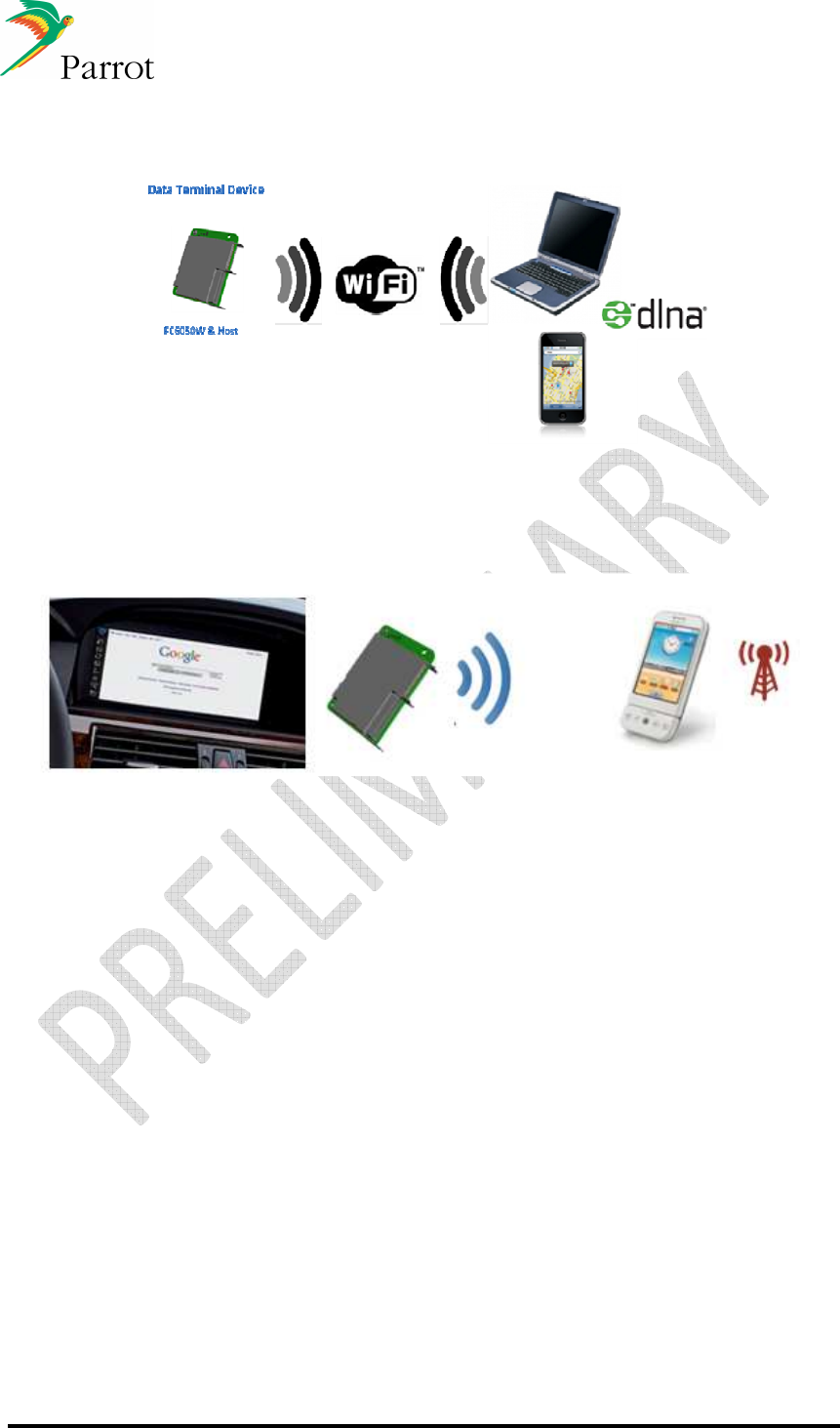
Universal Plug and play (AP and client)
Download or stream video and audio files from a UPnP server
5.4
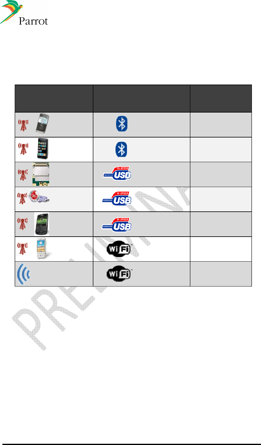
Wi-Fi tethering (client)
The mobile device acts as a modem and provides internet connection to the host
DATASHEET Confidential Information 14/84
Ref:
EL
-
2009
-
009
6 Internet connectivity solutions
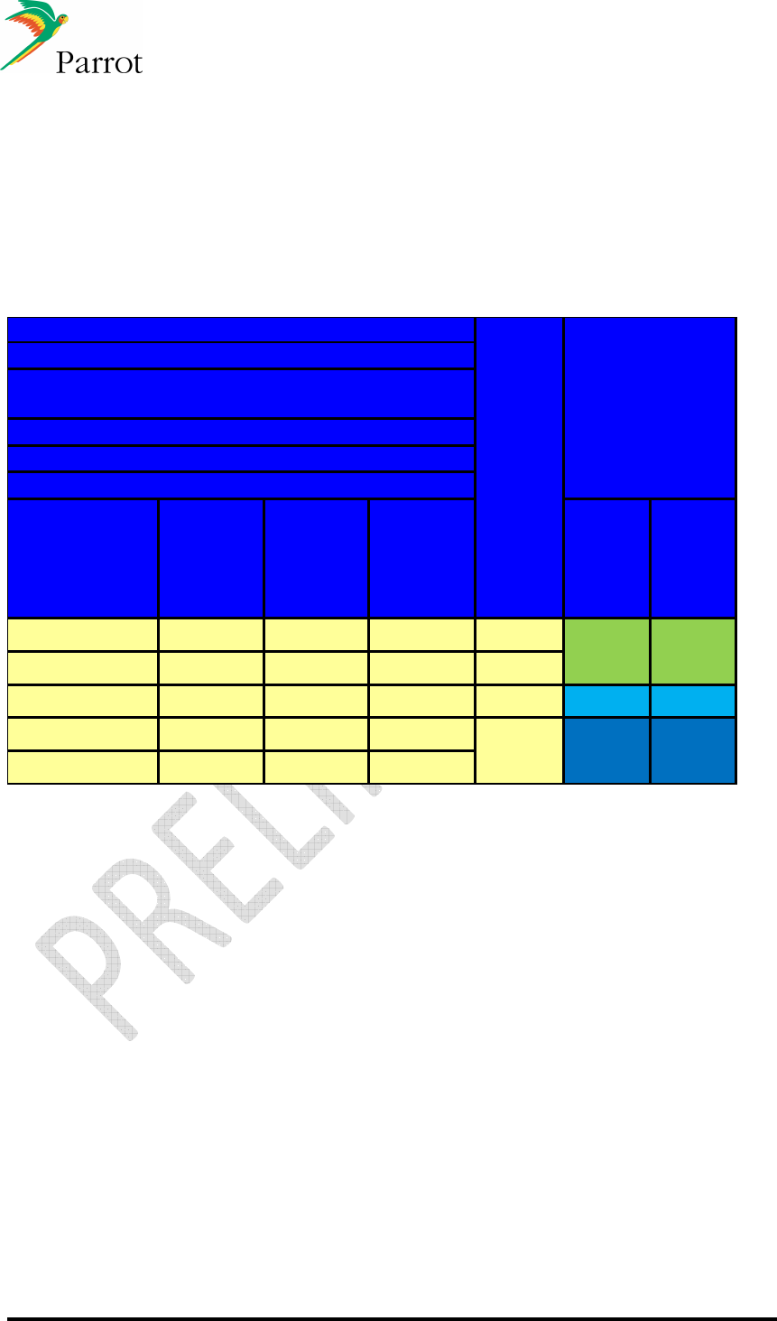
The FC6050 “full connectivity” modules offer the widest range of internet sources:
Internet source Transmission to the FC module HW requesite
Phone Bluetooth DUN Any FC module
Phone Bluetooth PAN AP Any FC module
NAD USB FC6050
NAD module
3G USB modem USB FC6050
3G USB modem
Phone Tethering over USB FC6050
Phone Tethering over WiFi FC6050W
Hospot WiFi Tethering over WiFi FC6050W
6.1
Internet sources - Overview
DUN, dial-up-network
The mobile device acts as a modem and provides the data to the module. DUN profile is
currently widely supported on the market.
PAN, personal area network
The mobile device supporting PAN-AP (access point) provides the data directly on Bluetooth
L2CAP layer in IP packets. The module acts as PAN-U (user).
NAD, network access device, optional feature
An external NAD can be integrated on the customer motherboard. Parrot module manages
Telephony, data call, SAP, Phonebook and messaging features of the NAD. All these
features are provided to the host using the same upper level commands. The Hardware
integration and monitoring are under the customer responsibility. NAD supplier choice shall
be jointly agreed with Parrot.

DATASHEET Confidential Information 15/84
Ref:
EL
-
2009
-
009
3G USB Dongle
Parrot currently supports over 200 3G dongles worldwide. Compatibility testing is done
continually to verify interoperability with new dongles on the market. Test teams are present
is in the US, Europe, Japan, Korea and China.
USB Tethering
As for DUN and PAN, the device acts as a modem and provides the data to the module over
USB. Feature availability is provider and OS dependant. Parrot currently supports Android,
iOS, RIM and Symbian OS.
Wi-Fi Tethering
Any mobile device supporting Wi-Fi access point feature can be used by Parrot module as
an additional internet source. This feature has to be enabled by the network provider.
6.2
Parrot router
:
In order to provide flexible network handling and configuration, Parrot developed a router
embedded on the FC6050.
It allows the host to connect any network interface available on the FC6050 (Wi-Fi, 3G
modem, DUN/PAN via BT, Tethering over USB, HOST). It is configurable through a user
friendly set of AT commands (Parrot’s HSTI) and makes it possible to enable internet
services (ftp, vnc, http, for example) on each interface.
6.3
Miscellaneous
The FC6050W needs to be informed of the provider’s DNS (Domain Name Server) IP
address. This information is transmitted to the FC6050W via an HSTI command.
Parrot's FC6050W does not do filtering (firewalling) on the host provided network
transactions, except what may be needed for its own safety. Hence, if some filtering must be
done for network operator or any other reason, it shall be done by the host. Thus, the host is
responsible for the incoming network traffic. Examples include blocking incoming
connections, restricting use to http and https protocols, forbidding POP/IMAP use, blocking
VOIP etc. (these examples come from common phone operator contractual regulations).

DATASHEET Confidential Information 16/84
Ref:
EL
-
2009
-
009
7 Host to FC6050B/W interface details
The architecture relies on 4 key features:
1. Using USB as a fast, standard physical medium – USB is used to exchange
commands, events, and user data between the host and Parrot's Wi-Fi enabled
FC6050W. A USB 2.0 High Speed link has a bandwidth of 480 Megabits per second
(60 Megabytes per second). Even with upper layer protocol overhead needed by the
USB physical medium, there is more than enough room for a quality network
connection. [As a point of reference, a typical PC network interface card (NIC) is
100Mbs. A full-blown heavy duty network server has 1000Mbs (1Giga bit per second)
NICs.]
2. Standard networking over USB protocols - Just as serial lines have been used as
the physical medium for networking for years (reference Point-to-Point Protocol), USB
can be used as the physical medium for standard TCP/IP networking. CDC ECM
(Communication Device Class, Ethernet Control Model) is the USB - Implementers
Forum standard for such use. Using such protocols, the USB connection appears to
the operating system as a Network Interface Card (NIC), ready to carry Ethernet
frames. From then on, all rich TCP/IP protocol stacks are available.
3. Parrot's HSTI library uses networking as its logical medium - The Parrot Host
Software Interface (HSTI) library (see section
8
) uses a network socket interface,
allowing command and event communication as on a network.
4. An inner, user-hidden network – This connection simply consists of just two nodes:
• the host processor
• Parrot’s Wi-Fi enabled OEM module.
The car information and entertainment system can be referred to as the host, and
Parrot's FC6050W module as the target. However, from a USB bus perspective (i.e.
according to USB standard terminology):
• the host is considered a “USB device”
• the Parrot's FC6050W target module is considered a “USB host”
The USB terminology of “USB host” and “USB device” does not interfere with the notion
of master / slave from a system perspective, but rather is a matter of hardware and
operating system stack configuration.
The networking architecture can be done using FC6050W as an USB device, and the
host as the USB host. However, in such a case, the use of USB media devices (for
example, MTP or USB flash drive with media files) cannot be done by the FC6050W,
even if a USB hub is used.
7.1
UART
Alternatively, if no USB port is available on the Host side, a serial port can be used to
control the FC6050 using Parrot’s HSTI command and control interface over UART.

DATASHEET Confidential Information 17/84
Ref:
EL
-
2009
-
009
7.2
Protocols used
Two types of protocols are used:
1. Standard networking over USB protocol, carrying both HTSI and internet data.
2. The Parrot's HSTI command and events protocol.
7.3
Standard networking over USB protocol for data transmission
The FC6050W handles a USB protocol named CDC ECM (Communication Device
Class, Ethernet Control Model) for networking over USB.
CDC ECM is the USB-Implementers Forum SIG standard for networking Ethernet over
USB. Widely used for cable DSL modem and USB-Ethernet dongles before the domestic
use of NIC became widespread, it has been an official part of the Linux OS since 2003.
CDC ECM goal is to use a USB connection to mimic NICs cards between a USB host
and a USB device, with their MAC and configurable IP addresses, able to convey any
Ethernet frames. These NICs can then be set up and used as any regular network card
would be. From a Linux application point of view, there isn’t any difference between a
USB CDC ECM network connection and a regular one. Actually, the Linux application is
not even aware of physical media used (USB rather Ethernet), since this media is hidden
behind the networking stack of the Linux OS.
RNDIS (Remote Network Driver Interface Specification) is Microsoft vendor-specific,
non-standard way to carry Ethernet over USB. Although RNDIS is not recommended,
RNDIS may be used as a replacement for CDC ECM.
8 Software interface, HSTI Library
The FC6050x software interface, HSTI Library, is defined by a high level command set
on top of Parrot Libraries.
This interface software is based on the HSTI commands defined by Parrot. These
commands are fully documented and the software library is provided by Parrot for easy
implementation in the host CPU.
Some commands are used to manage Bluetooth related functions like device pairing and
connection management as well as the acoustic and speech recognition functions.
Other commands are used to manage Music connected on USB ports.
The HSTI Command List and Bluetooth AT Command Software Specification are
available upon request.
The Bluetooth software stack, BLUES, supports Unicode, which allows the management
of language accents and allows for phonebook management in any language.

DATASHEET Confidential Information 18/84
Ref:
EL
-
2009
-
009
8.1
Parrot’s HSTI protocol for network connectivity
HSTI is Parrot's standard API used over its product range. It provides a rich yet simple,
fully documented set of more than 250 high-level commands to pilot the FC6050. The
host sends AT commands, and registers to events to be notified of changes occurring in
the FC6050.
HSTI is available and used on Linux operating system.
HSTI can be used over a network socket or a serial line (UART).
Some HSTI commands are specifically designed to handle network connectivity. For
examples, see the document “Parrot Host Software Interface Specification”. Some
networking commands are exemplified below.
The following steps are required in order for the host CPU to establish a dialog and take
command of the FC6050;
1. Setup the USB link to FC6050 as CDC ECM.
2. Configure this new Ethernet interface (IP address, netmask, broadcast address). For
ease of use, and since there is no added value in making these parameters dynamic,
these IP parameters should be fixed in the product (example 192.168.64.1) - to be
discussed with Parrot.
3. In the host application, open a standard internet socket. This socket will be used to
communicate with the FC6050 via HSTI. The port used for this socket should be a
fixed one, that does not interfere with any commonly used protocol (example value:
23000) – to be discussed with Parrot. From this point, regarding communication to
the FC6050, the host application will not have to care about networking any more.
The socket and USB network connection will be used transparently between the 2
CPUs to carry all HSTI dialog.
4. Register to HSTI events for notification. Events can either be responses from FC6050
to explicit host commands, or unsolicited, asynchronous events such as “new USB
stick insertion”, or “3G dongle insertion”.
5. The host can then send commands to the FC6050 using the HSTI API.
Regarding networking, some additional steps are required. As an example, if the internet
connectivity comes from a 3G dongle plugged into the FC6050 (see section 4, scenario
2):
• The FC6050 shall notify the host of the availability of the 3G dongle by sending an
event.
• If the host decides to enable the internet connection, it prompts the user, for the PIN
code. The prompt and PIN entry is done through the host user interface (screen and
keyboard or touch screen).
• The host sends the PIN code to the FC6050, via an HSTI command.
• The FC6050 manages the 3G dongle, and reports connection status to the host
(example: connection established, or PIN code rejected)

DATASHEET Confidential Information 19/84
Ref:
EL
-
2009
-
009
Some things to notice:
• The host may choose to make the internet connection available to the FC6050 Wi-Fi
access point or not. In all cases, the host is in command to dynamically enable or
disable capabilities via the FC6050.
• If the internet connectivity comes from the host (section 4, scenario 1), then the DNS
IP address has to be sent to the FC6050, using the dedicated HSTI command.
• If the host requires internet connectivity for itself from the FC6050 (section 4, third
scenario), then it should do so explicitly and query the FC6050 for the DNS address,
again using the dedicated HSTI commands.
• Internet connectivity provided by the FC6050 (second and third use case) is not “all or
nothing”. It can be used for;
o Wi-Fi access point only
o host only
o both Wi-Fi access point and host use
o disabled
In all relevant cases, the internet networking traffic between the host and the FC6050 will
use the same network interface established before via USB CDC ECM to carry HSTI
commands. This is done transparently so that applications, either on host or on the
FC6050, do not need to handle it (unless of course the host application is willing to do
so).
As a benefit inherited from its rooted serial line interface, the network traffic generated by
the HSTI dialog is extremely low: a typical HSTI query or reply ends up in a dozen or
less bytes of payload. Thus, this HSTI traffic does not interfere with the network
bandwidth available to Wi-Fi users or the host.
Here is an example demonstrating a typical host-side HSTI sequence to setup Wi-Fi,
choose a security level and setup a Wi-Fi network name:
/* set the Wi-Fi “on”, Access Point mode : */
HSTI_CmdAPI_Send_WSWM(AP);
/* Send access point configuration : set the security protocol to WPA */
HSTI_CmdAPI_SendWAPC(SET, SECURITY, WPA);
/* Access point configuration : the SSID naming the Wi-Fi network is “my car network” */
HSTI_CmdAPI_SendWAPC_STR(SET, SSID, “my car network”);
DATASHEET Confidential Information 20/84
Ref:
EL
-
2009
-
009
9 Memory configurations
The below table provides an idea of the standard memory configuration.
This configuration shall be adjusted with Parrot team depending on your features and
requirements.
Memory
Configuration
Nuance
VR & SVOX
TTS
Concertos
RAP(*)
Gracenote
can be
added
FLASH
(NAND)
MDDR
Mbits
version 1
-
version 2
-
version 3
1 to 4 2Gb 512
version 4
version 5
2561Gb
5124Gb1 to 12
FC6050B&W Configurations:
Number of
Languages
with
VR & TTS
Memory Size
-Telephony, Phonebook, Audio streaming, BT, Wifi
- up to 10 phonebooks of up to 5000 contacts each,
5 numbers per contact, 300 SMS
-Concertos: up to 4 Databases with 40 000 songs each
RAP: voice recognition multimedia (up to 20 000 artists or albums)
-Gracenote European or US database
Notes:
• The use of some codecs require that a specific fee to be paid directly to the proper
organization
• An iPod chip must be externally connected to the module (via I²C interface)
• Concertos limitation of 3 x 10.000 songs for version 2.

DATASHEET Confidential Information 21/84
Ref:
EL
-
2009
-
009
10 Speaker Independent Voice Recognition and Text to
Speech
10.1
Voice Recognition principles
NUANCE VoCon 3200 V3.3 is a training-less speaker independent speech recognition
engine offered on both FC6050B and FC6050W. VoCon 3200 V3.3 features include:
• Voice recognition: words are recognized without previous training
• Acoustic models provide accuracy improvement, especially for digits recognition
• Continuous voice recognition: no need for blanks between words
• New words learning (Voice tags), speaker dependent speech recognition (100 Voice
tags, 2kbytes by Voice tag)
• Noise robustness and accuracy in an automotive environment: engine, click-button
etc…
• Significant improvement in recognition rate
• Unsupervised speaker adaptation
• User-friendly flexibility for calling phonebook entries, digit dialing, and common
command and control
• Supporting the possibility to recognize multimedia names (artists, albums, genres,
playlists)
• Users can also control other vehicle functions by voice such as door locks, window
motors, and climate control settings
• Simple command and control voice interfaces for AM/FM radio, TV/DAB channels
and CDs replace several button presses;
o “radio ninety seven point nine”
o “CD play track twelve”
10.2
Text To Speech (TTS)
Text to Speech (TTS) on FC6050B & FC6050W is based on SVOX Automotive Speech.
SVOX Automotive TTS solutions are tailored for noisy car environments and enjoy a
reputation for industry-leading quality. They power many of the most advanced and
successful in-dash infotainment systems in the market. SVOX TTS technology is
characterized by natural and clear sound as well as unique polyglot capability – the
same voice can speak multiple languages like a native speaker.
SVOX TTS is not limited in vocabulary. It can be used to confirm the orders identified by
a voice recognition process or for reading vehicle commands, songs titles or phonebook
entries.
Abbreviations, tags, symbols (emoticons) are converted into readable text (grapheme-to-
grapheme conversion). In addition, the SVOX TTS engine contains an advanced text
pre-processor that automatically handles common specifications for date and time.
SVOX provides an excellent quality prosody (i.e. sentence intonation) using state-of-the-
art prosody modelling technology. Accent values, phrase types, and phrase boundary
positions are taken into account for the determination of the speech melody (pitch
contour) and sound durations.

DATASHEET Confidential Information 22/84
Ref:
EL
-
2009
-
009
Voice Recognition and TTS voice is available in both FC6050B and FC6050W for the
following languages:
01) US English
02) CA French
03) N.A. Spanish
04) UK English
05) French
06) Italian
07) German
08) Spanish
09) Dutch
10) Danish
11) Swedish
12) Portuguese
13) Brazilian Portuguese
14) Turkish
15) Russian
16) Polish
17) Czech
18) Mandarin Chinese
19) Korean
20) Japanese
10.3
Voice Recognition for Phonebook Access
The FC6050B and FC6050W support the use of Nuance VoCon 3200 version 3.3 voice
recognition algorithms to access phonebook entries. Up to 9 languages can reside
simultaneously depending on the size of the flash and RAM (See section 9). Only one
language can be active at a time.
10.4
Voice Recognition for Music Data on external sources
10.4.1 RAP
RAP is an optional Parrot-developed voice recognition gateway. In combination with the
voice recognition option and the CONCERTOS software option it provides the user the
ability to select music on multiple external sources and to operate player functionalities
by voice commands. RAP allows recognition by album title, music type (genre) or artist
name regardless of where the media file resides.
The voice recognition latency is, on average, 1.8 seconds for a database size of 20,000
Albums or Artists. The latency can be improved by reducing the number of Albums or
Artists (~1s for 10 000). Based on trials with the French Parrot test database the voice
recognition accuracy is ~ 85 %.
The maximum number of recognizable items depends on the available memory.
10.4.2 Gracenote® for Music Data on external sources
Gracenote's technology is being relied on by many of the world's leading consumer
electronic devices and media software applications. Gracenote uses a multi-step
recognition method to enable identification, categorization, and organization of digital
music. Regardless of source or format, Gracenote gives music fans the tools to manage
and enjoy their music collections.
10.4.2.1 MediaVOCS TM
MediaVOCS, provided by Gracenote, is an advanced speech-based media database.
This database includes phonetic transcriptions for alternate artist, album and track
names. Even common names are often multiethnic, abbreviated or nicknames which
cannot be recognized by a standard voice recognition database. Based on Parrot
studies, adding Gracenote MediaVOCS to the voice recognition improves the recognition
rate by a factor of 33% on artist names and 16% on album names.
Gracenote MediaVOCS is available in the following languages:
US English
UK English
French
Italian
German
Spanish
Canadian French
Mexican Spanish

DATASHEET Confidential Information 23/84
Ref:
EL
-
2009
-
009
10.4.2.2 Playlist Plus
Parrot also offers an additional tool from Gracenote known as Playlist Plus
TM
. Designed
to work with MediaVOCS, Playlist Plus analyzes the metadata for music brought into the
vehicle and offers a variety of playlists for the music library. These playlists may be
either pre-set or user customized. In addition, the user may select “More Like This” and
hear other songs in the music library of a similar genre to the song currently playing.
10.4.3 Natural Language Understanding (NLU)
The Parrot FC6XX0 product line offers an advanced voice recognition system based on
Grammar based NLU (Natural Language Understanding, VoCon3200 version 3.3 )
With NLU, the user has the ability to control various vehicle feature by voice without
"being constrained" by traditional voice recognition menu trees or categories (music,
phone book, ...).
All Parrot features and other vehicle functions can be controlled via voice from the press
of a single “push-to-talk” (PTT) button.
With NLU, the user can skip the step of narrowing the choices:
• Selection of Phone Number from Phonebook
• “I want to call John Smith”
• “Call John Smith”
• “Call John Smith at home”
• “Call Smith at the office”
• “Call John Smith on Mobile
• Selection of Music from Music Library
• “Play something from John Mayer”
• “Play Parachutes from Coldplay”
• “Play Bob Marley” [Note: this command works even though the official artist name is
“Bob Marley and the Whalers”]
• “Play Jazz”
• “Play Alternative”
• “Play Super Hits of Miles Davis
These are just a sample of what is possible with NLU.
Other features, not residing on the Parrot FC6XX0 module can also benefit from NLU.
This includes use cases such as tuning of a radio station or activating a rear-camera
image:
• “Tune to 97.1 Megahertz”
• “Tune to 950 AM”
• “Switch to FM”
• “Seek”
• “Play AM preset 3

DATASHEET Confidential Information 24/84
Ref:
EL
-
2009
-
009
10.4.3.1 Nuance Music Pre-Processor (MPP)
The Parrot RAP multimedia library option includes Nuance Music Pre-Processor (MPP)
to facilitate flexible voice recognition access to music. Specifically, Nuance MPP allows
the user to speak only a portion of the album title or artist name and find the intended
song. Flexible music selection allows users to speak the most common variations and
still be understood.
“Avia” for “Avia feat. Raz Ohara”
“Nuage” for “Nuage (Take 2)”
“Police” for “The Police”
With Nuance MPP, users can speak album titles are artist’s names that they know are
present on their own music player without looking at any visual prompt.
10.4.3.2 ddG2P / CLC MP3
Nuance ddG2P MP3 and CLC MP3 are Nuance’s high speed, small footprint
Graphemes to Phonemes converters (G2P, converting the text to phonetics) dedicated
to the music domain.
10.5
Remote speech to text engine
Parrot is evaluating different solutions of remote voice recognition.
Based on a client-server model, they will allow the end user to use off-board voice
recognition engines, running on centralized servers, accessible through an internet
connection.
• The benchmark includes:
o Dragon from Nuance
o Google
o Text Friendly
• Feature available on FC6050 from 2012.
DATASHEET Confidential Information 25/84
Ref:
EL
-
2009
-
009
11 Electrical specifications
11.1
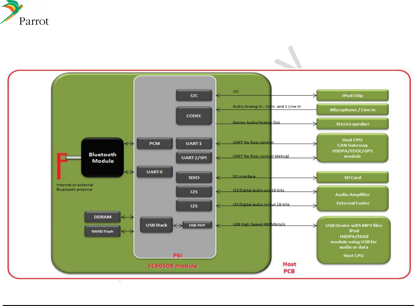
Hardware architecture FC6050B
DATASHEET Confidential Information 26/84
Ref:
EL
-
2009
-
009
11.2
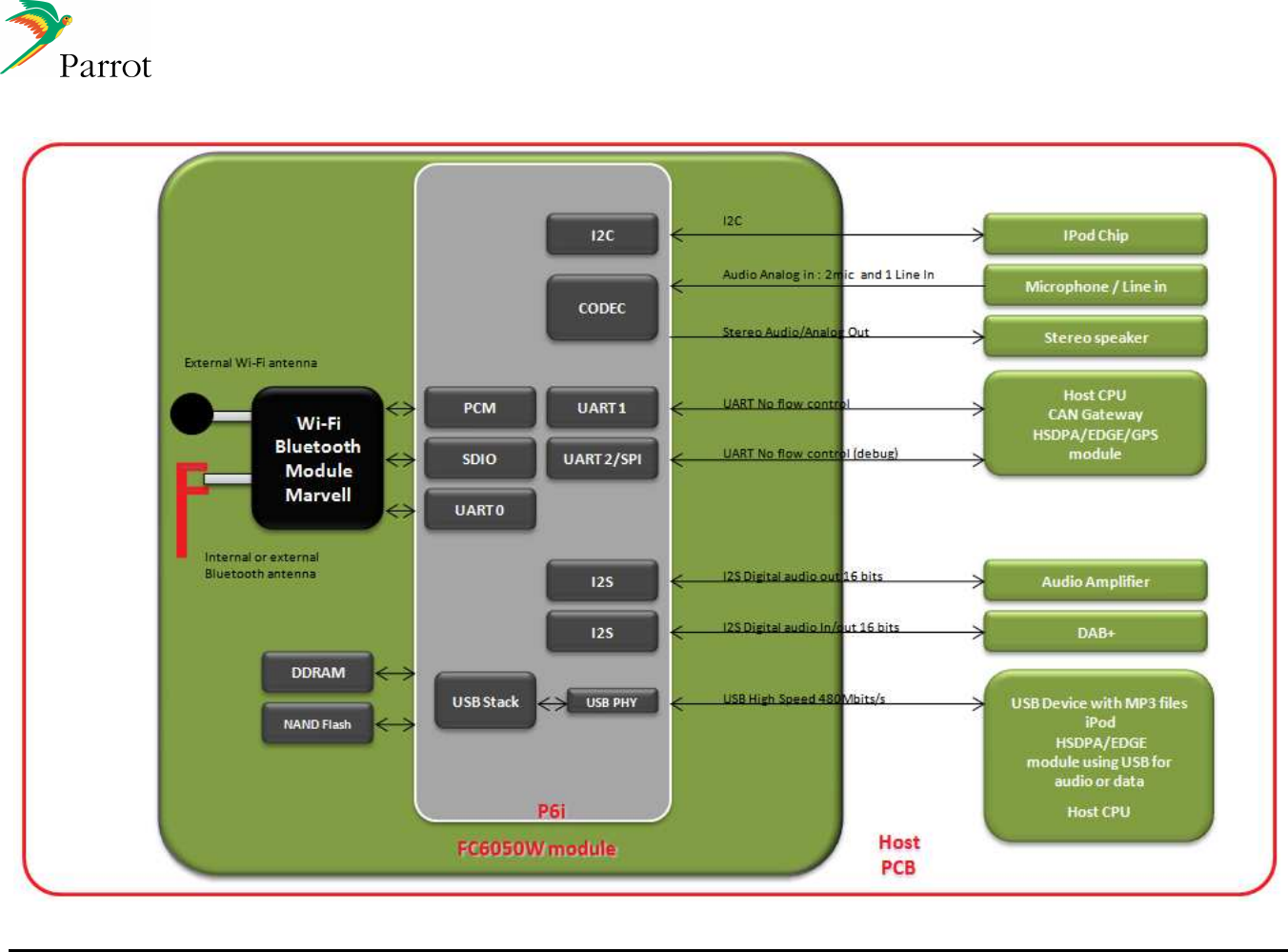
Hardware architecture FC6050W
DATASHEET Confidential Information 27/84
Ref:
EL
-
2009
-
009
11.3
Pinout (FC6050W and FC6050B)
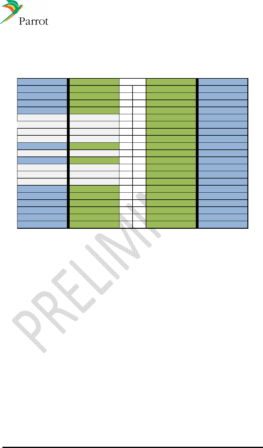
11.3.1 Pinout table 40 pins version
FC6050W FC6050B FC6050B FC6050W
USB_VBUS USB_VBUS 1 2 RESET_IPOD RESET_IPOD
USB_DP USB_DP 3 4 I2C_CLK I2C_CLK
USB_DN USB_DM 5 6 I2C_DAT I2C_DAT
GND GND 7 8 UART_AT_TX UART_AT_TX
USB_PWR_EN SD_WP 9 10 UART_AT_RX UART_AT_RX
USB_OVERCURRENT
SD_DETSW 11 12 UART_DBG_TX UART_DBG_TX
USB_ID SD_DAT1 13 14 UART_DBG_RX UART_DBG_RX
GPIO_MUTE SD_DAT0 15 16 VCC VCC
VCC VCC 17 18 I2S_IN1 I2S_IN1
I2S_IN2 SD_CLK 19 20 I2S_OUT2 I2S_OUT2
GND GND 21 22 I2S_OUT1 I2S_OUT1
GPIO_1 SD_CMD 23 24 I2S_SYNC I2S_SYNC
GPIO_2 SD_DAT3 25 26 I2S_CLK I2S_CLK
GPIO_3 SD_DAT2 27 28 I2S_MCLK I2S_MCLK
nRESET nRESET 29 30 BOOTS BOOTS
LINE_OUT_L LINE_OUT_L 31 32 LINE_OUT_R LINE_OUT_R
MIC_PWR MIC_PWR 33 34 GND GND
MIC_1_P MIC_1_P 35 36 MIC_2_P MIC_2_P
MIC_1_N MIC_1_N 37 38 MIC_2_N MIC_2_N
LINE_IN_L / CTS LINE_IN_L / CTS 39 40 LINE_IN_R / RTS LINE_IN_R / RTS
Pin #

DATASHEET Confidential Information 28/84
Ref:
EL
-
2009
-
009
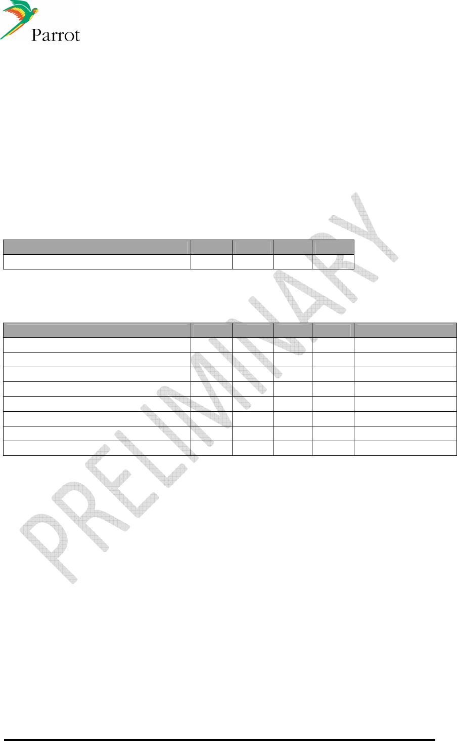
11.3.2 FC6050W Pinout table
PIN FUNCTION PIN
TYPE
COMMENT
1
USB_VBUS
I
USB VBUS
3
USB_DP
I/O
USB DATA +
5
USB_DM
I/O
USB DATA -
7 GND P Ground
9
USB_PWR_EN
O
USB Power Enable
11
USB_OVERCUR
I
USB Overcurrent
13
USB_ID
I/O
USB ID
15
GPIO_MUTE
I/O
GPIO Mute
17 VCC P Power supply : 3.3v
19
I2S_IN2
I
Digital audio data input 2
21 GND P Ground
23
GPIO_1
I/O
GPIO 1
25
GPIO_2
I/O
GPIO 2
27
GPIO_3
I/O
GPIO 3
29
nRESET
I
Discrete reset signal – active low
31
LINE_OUT_L
O
Analog audio output – Left
33
MIC_PWR
O
Microphone bias voltage
35
MIC_1_P
I
Positive microphone 1 input
37
MIC_1_N
I
Negative microphone 1 input
39
LINE_IN_L
I
Analog audio input - Left

DATASHEET Confidential Information 29/84
Ref:
EL
-
2009
-
009
PIN FUNCTION PIN
TYPE
COMMENT
2
RESET_IPOD
O
IPOD Reset
4
I2C_SCL
O
I2C Clock
6
I2C_SDA
I/O
I2C Data
8
UART_AT_TX
O
AT Commands & flash update UART output
10
UART_AT_RX
I
AT Commands & flash update UART input
12
UART_DBG_TX
O
Debug UART output
14
UART_DBG_RX
I
Debug UART input
16 VCC P Power supply : 3.3v
18
I2S_IN1
I
Digital audio data input 1
20
I2S_OUT2
O
Digital audio data output 2
22
I2S_OUT1
O
Digital audio data output 2
24
I2S_FSYNC
O
Digital audio frame synchronization
26
I2S_CLK
O
Digital audio clock
28
I2S_MCLK
O
Digital audio master clock
30
BOOTS
I
Discrete boots mode signal – active high
32
LINE_OUT_R
O
Analog audio output - Right
34 GND P Ground
36
MIC_2_P
I
Positive microphone 2 input
38
MIC_2_N
I
Negative microphone 2 input
40
LINE_IN_R
I
Analog audio input - Right
DATASHEET Confidential Information 30/84
Ref:
EL
-
2009
-
009
12 Electrical specifications
12.1
Absolute maximum ratings
Operating temperature range ....................................................................-40°C t o +85°C
Storage temperature range......................................................................-40°C t o +125°C
ESD sensitivity according ES-XW7T-1A278-AC........................................................±4kV
12.2
Power Supply
The FC6050W module is supply by a 3v3 voltage.
12.2.1 Power Pin
Parameter Min Typ Max Unit
Normal supply 3,2 3,3 3,6 V
12.2.2 Power consumption
Feature Min Typ Max Unit Comment
Stop mode - 18 - mA NReset active
Run/Standby mode - 150 - mA
Hands Free and Audio streaming mode - 210 - mA
Wifi Active (Labtool) - 217 - mA
Wifi Packet 802.11b (Labtool) - 295 - mA
Wifi Packet 802.11g (Labtool) - 232 - mA
Peak current at startup - 218 - mA
Peak current at startup (duration) - 200 - us
DATASHEET Confidential Information 31/84
Ref:
EL
-
2009
-
009
12.3
Reset pin
nRESET should be driven Low by the Host as long as VCC is not stable within the specified range.
Parameter Min Typ Max Unit Comment
nRESET VIL -0,3 - 0,89 V -
nRESET VIH 2,54 - 3,6 V -
12.4
Firmware Update
BOOTS
is the Flash update signal. When BOOTS is high as nRESET goes high, FC6050 boot is
redirected to the USB link thanks to which the flash memory can then be updated.
Parameter Min Typ Max Unit Comment
BOOTS VIL -0,3 - 0,5 V -
BOOTS VIH 1 - 3,6 V -
BOOTS internal pull-down - 47k - Ohm -
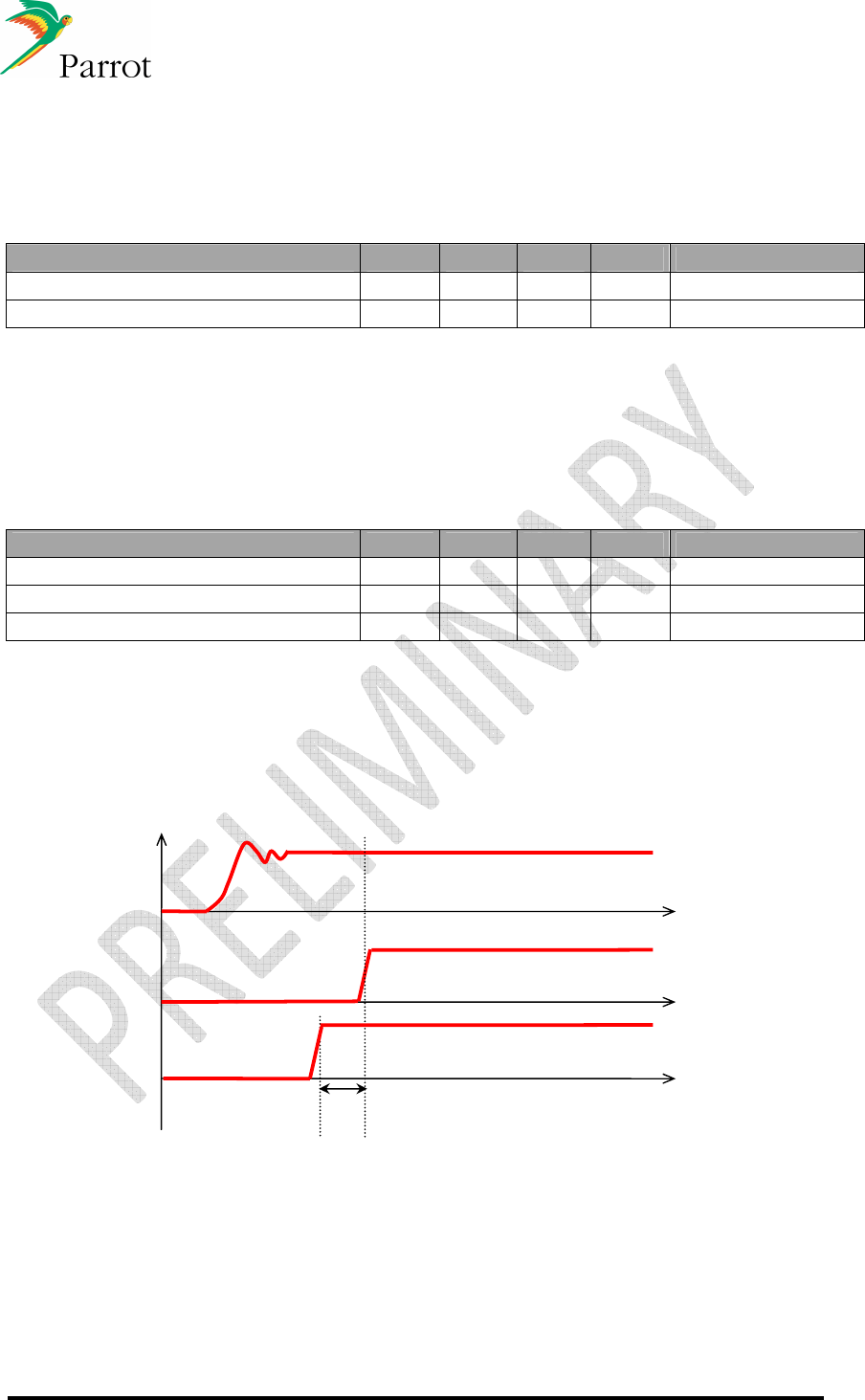
To boot in flash-update mode, the following sequence should be respected:
When a 3V3 power source is established, pull BOOTS signal.
Wait at least 30µs and release NRESET signal to start the flash update.
Figure: Time diagram to boot in flash-update mode
3V3
NRESET
BOOTS
30µs
DATASHEET Confidential Information 32/84
Ref:
EL
-
2009
-
009
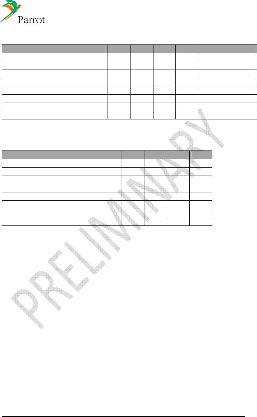
12.5
GPIOs
Parameter Min Typ Max Unit Comment
Input Voltage -0,3 - 3,6 V
Output Voltage -0,3 - 3,6 V
Input Low Voltage VIL -0,3 - 0,89 V
Input High Voltage VIH 2,54 - 3,6 V
Hysteresis Voltage 0,4 - - V
Low Level Output Voltage VOL - - 0,4 V
High Level Output Voltage VOH 2,9 - - V
Output Current 5,4 - 32 mA
12.6
UART
Parameter Min Typ Max
Input high level 2,9 - 3,6 V
Input low level -0,3 - 0,4 V
Output high level 2,9 - 3,6 V
Output low level -0,3 - 0,4 V
Rise time - - 50 ns
Fall time - - 50 ns
Baud rate - - 115,2 kbps
Reception Baud rate errors -5,48 - 4,7 %
DATASHEET Confidential Information 33/84
Ref:
EL
-
2009
-
009
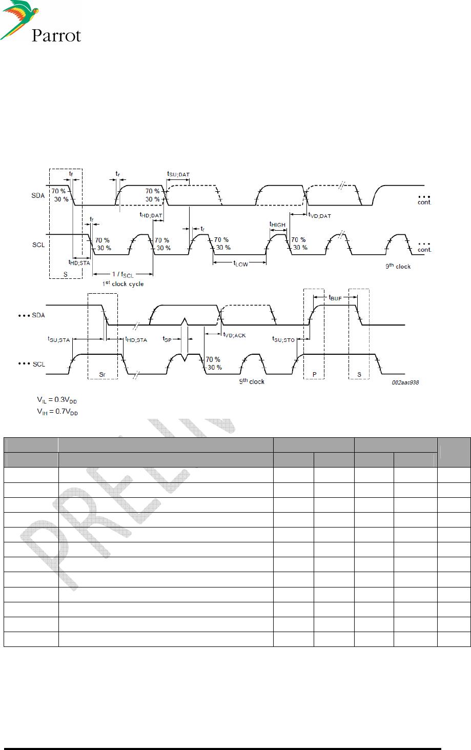
12.7
I2C
The interface defines 2 transmission speeds:
•
Normal: 100 kbps
•
Fast: 400 kbps
Standard Mode Fast Mode
Symbol Parameter Min Max Min Max Unit
fSCL SCL clock frequency 0 100 0 400 kHz
tHD;STA hold time; Start condition 4 - 0,6 - uS
tLow LOW period of SCL clock 4,7 - 1,3 - uS
tHigh HIGH period of SCL clock 4 - 0,6 - uS
tsu ; STA set-up time for a repeated START condition 4,7 - 0,6 - uS
thd ; DAT data hold time 5 - - - uS
tsu ; DAT data set-up time 0,25 - 0,1 - uS
tr Rise time of both SDA ans SCL signals - 1 - 0,3 uS
tf fall time of both SDA and SCL signals - 0,3 - 0,3 uS
tSU;STO set-up time for STOP condition 4 - 0,6 - uS
tVD;DAT data valid time - 3,45 - 0,9 uS
tVD;ACK data valid acknowledge time - 3,45 - 0,9 uS
DATASHEET Confidential Information 34/84
Ref:
EL
-
2009
-
009
12.8
Audio
12.8.1 Analog out
Conditions unless otherwise noted : Tamb.=25°C; Vdd =3V3
Parameter Conditions Min. Typ. Max.
Unit
Full scale output voltage 0.9 Vrms
Load resistor 7 10 - k
Ω
THD+N 0.02 - 0.05 %
SNR 80 - 96 dB
F=1kHz - - 70 dB LR Crosstalk F=10kHz - - 70 dB
Bandwidth -3dB 20 - 20k Hz
12.8.2 Analog in
Conditions unless otherwise noted : Tamb.=25°C; Vdd =3V3
Parameter Conditions Min. Typ. Max.
Unit
Full scale input voltage THD<n% - 0.9 - Vrms
Input resistance - 10 - k
Ω
THD+N 0.02 - 0.05 dB
SNR 80 - 96 dBA
F=1kHz - - 70 dB LR Crosstalk F=10kHz - - 70 dB
Bandwidth -3dB 20 - 20k Hz
12.8.3 Microphone input
Conditions unless otherwise-noted : Tamb.=25°C; Vcc =3V3
Parameter Conditions Min. Typ. Max. Unit
Maximum input impedance - 10 - k
Ω
Max. AC input voltage - - 0.9 V
rms
SNR, 1kHz 80 - 96 dB
THD - 0.05 %
Bandwidth Low - - 20 Hz
Bandwidth High 20 - - kHz
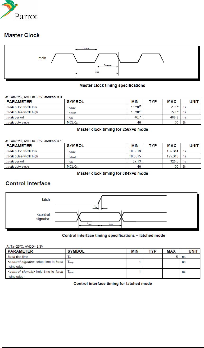
DATASHEET Confidential Information 35/84
Ref:
EL
-
2009
-
009
12.9
I2S
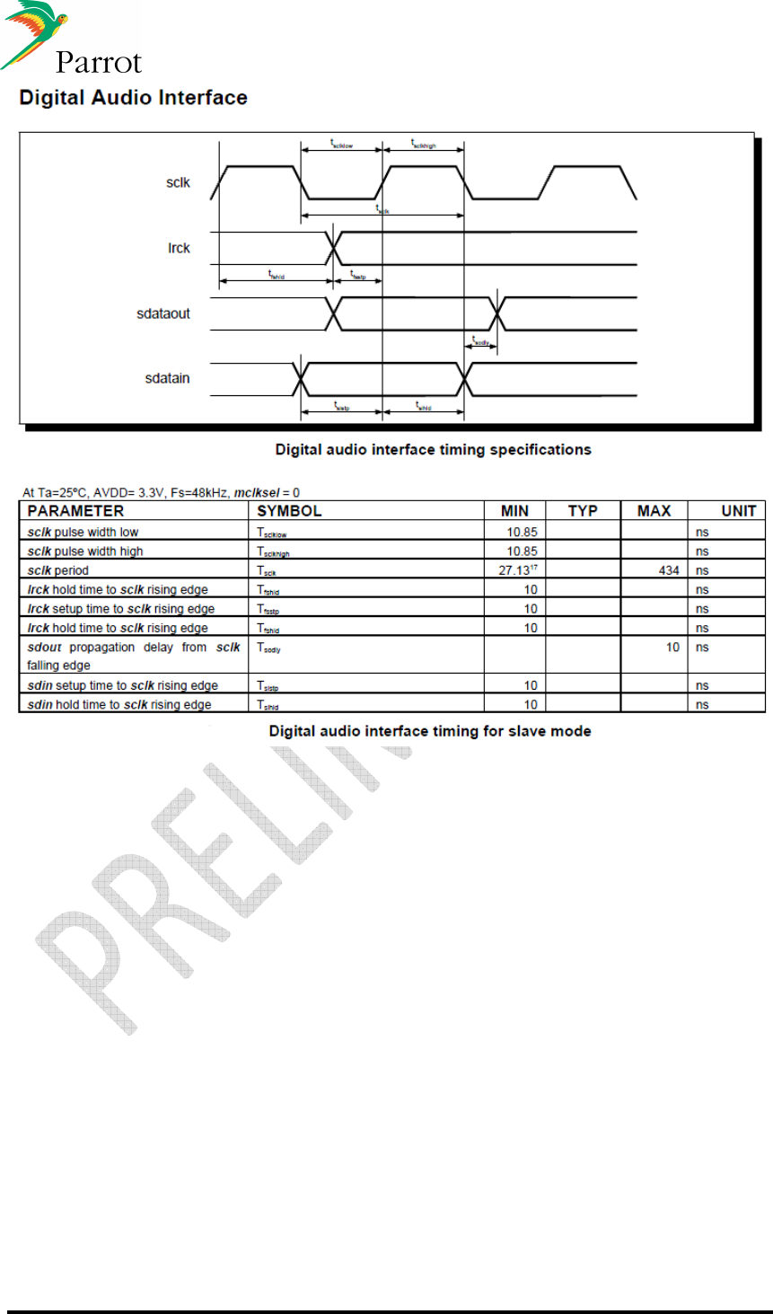
DATASHEET Confidential Information 36/84
Ref:
EL
-
2009
-
009
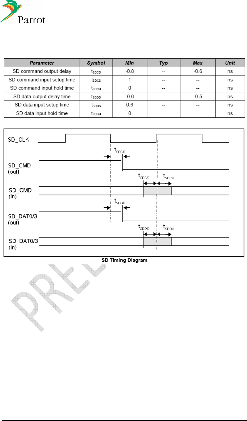
DATASHEET Confidential Information 37/84
Ref:
EL
-
2009
-
009
12.10
SDIO

DATASHEET Confidential Information 38/84
Ref:
EL
-
2009
-
009
12.11
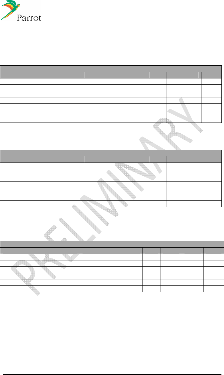
USB
Conditions unless otherwise noted : Tamb.=25°C; Vdd =3V3; Cload=50pF
Parameter Conditions Min. Typ. Max. Unit
DC CHARACTERISTICS
LOW SPEED / FULL SPEED FUNCTIONALITY
Differential receiver input
sensitivity |(D+)-(D-)| 0.2 - - V
Differential receiver common
mode voltage range 0.8 - 2.5 V
Single ended receiver low level
input voltage - - 0.8 V
Single ended receiver high level
input voltage 2.0 V
Single ended receiver hysteresis 0.05 0.15 V
Low level output voltage Rload=1.5k
Ω
to3V3 0.3 V
High level ouput voltage Rload=15k
Ω
to GND 2.8 3.6 V
HIGH SPEED FUNCTIONALITY
Differential receiver input
sensitivity 0.1 V
Differential receiver common
mode voltage range -
0.05 0.5 V
Squelch threshold 0.1 V Squelch detection threshold
(differential) Un-squelch threshold 0.15 V
Low level output voltage Rload=45
Ω
to GND -
0.01 0.01 V
High level output voltage Rload=45
Ω
to GND 0.36 0.44 V
Idle level output voltage Rload=45
Ω
to GND -
0.01 0.01 V
Chirp-J output voltage Rload=45
Ω
to GND 0.7 1.1 V
Chirp-K output voltage Rload=45
Ω
to GND -0.9 -0.5 V
Transceiver input capacitance Pin to GND - - 15 pF
AC CHARACTERISTICS
LOW SPEED FUNCTIONALITY
Rise time 10% to 90% 75 - 300 ns
Fall time 10% to 90% 75 - 300 ns
Differential Rise / Fall time
matching 80 125 %
FULL SPEED FUNCTIONALITY
Rise time 10% to 90% 4 20 ns
Fall time 10% to 90% 4 20 ns
Output signal crossover voltage 1.3 2.0 V
Differential Rise / Fall time
matching 90 111.1
%
HIGH SPEED FUNCTIONALITY
Differential Rise time 500 ps
Differential Fall time 500 Ps
DATASHEET Confidential Information 39/84
Ref:
EL
-
2009
-
009
12.12
Wifi
802.11b RF System Specifications
Parameter Test Condition Min Typ Max Unit
Transmit Power Output 13 15 17 dBm
Receive Sensitivity 11 Mbps, 8% PER - -84 dBm
Transmit Frequency Offset - +/-10 ppm
- 40@fc±11MHz - dBc
Spectral Mask Max. TX Power - 60@fc±22MHz dBc
Error Vector Magnitude Max. TX Power @
11Mbps - 10 - %
Carrier Suppression Max. TX Power - -25 dBc
Features Description
Frequency Band 2.4000 – 2.4835 GHz (2.4 GHz ISM Band)
Number of channels 14 channels (f=2412+n*5 MHz, n=0,…,12; channel 14=2484MHz)
Modulation
OFDM, DSSS (Direct Sequence Spread Spectrum),
DBPSK,DQPSK, CCK , 16QAM, 64QAM
Supported rates 1, 2, 5.5, 11, 6, 9, 12, 18, 24, 36, 48, 54 Mbps
Maximum receive level - 10dBm (with PER < 8%)

DATASHEET Confidential Information 40/84
Ref:
EL
-
2009
-
009
802.11g RF System Specifications
Parameter Test Condition Min Typ Max
Unit
Transmit Power Output 10 12 14 dBm
6 Mbps, 10% PER - -89 - dBm
9 Mbps, 10% PER - -88 - dBm
12 Mbps, 10% PER - -87 - dBm
18 Mbps, 10% PER - -84 - dBm
24 Mbps, 10% PER - -81 - dBm
36 Mbps, 10% PER - -77 - dBm
48 Mbps, 10% PER - -73 - dBm
Receive Sensitivity
54 Mbps, 10% PER - -72 - dBm
Transmit Frequency Offset -10 - +10 ppm
- -30@fc±11MHz - dBc
- -40@fc±20MHz - dBc
Spectral Mask Max. TX Power
- -50@fc±30MHz - dBc
Error Vector Magnitude
Max. TX Power @
54Mbps - 2.8 - %
Carrier Suppression Max. TX Power - -25 - dBc

DATASHEET Confidential Information 41/84
Ref:
EL
-
2009
-
009
12.13
Bluetooth
Features Description
Frequency Band 2.4000 – 2.4835 GHz (2.4 GHz ISM Band)
Number of channels 79 channels (f=2402+k MHz, k=0,…,78)
Modulation FHSS (Frequency Hopping Spread Spectrum), GFSK
Supported rates 1, 2, 3 Mbps
Maximum receive level - 3dBm
Output Power - 6dBm~4dBm
For all basic rate packet types BDR : dBm @ 0.1% BER
Sensitivity π/4DQPSK & 8DPSK EDR : dBm @ 0.1% BER
DATASHEET Confidential Information 42/84
Ref:
EL
-
2009
-
009
12.14
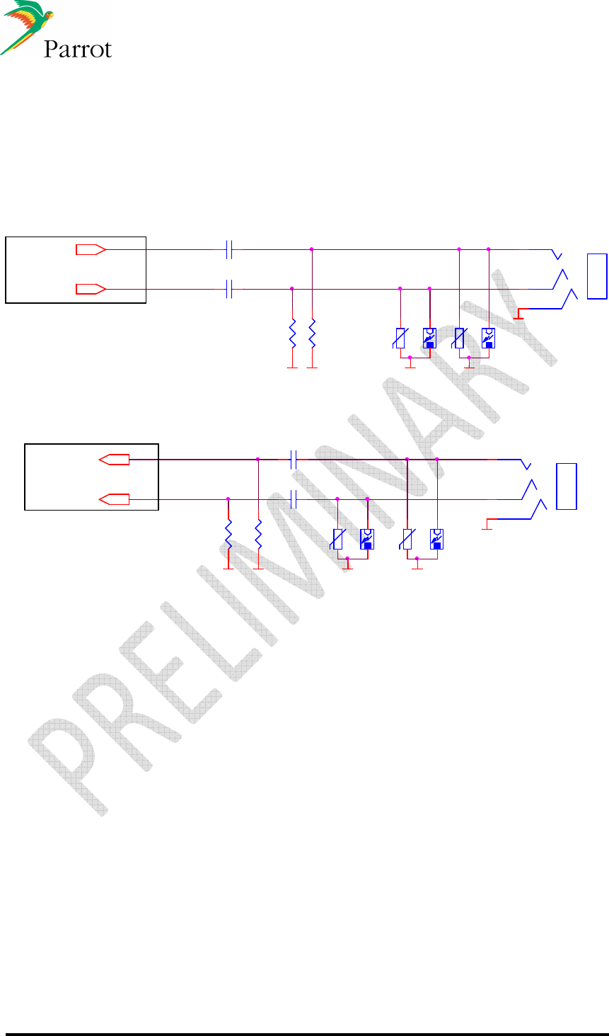
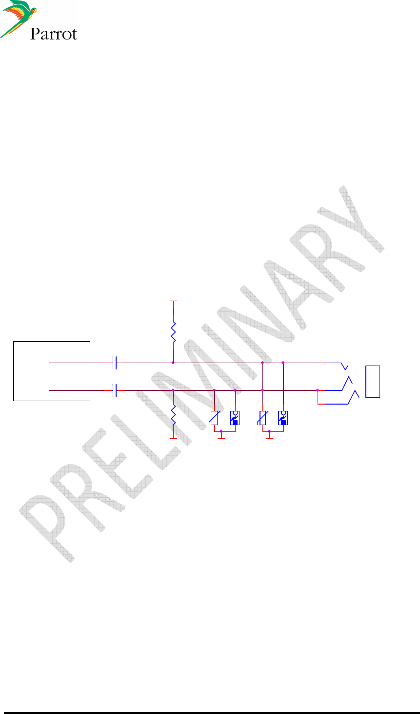
Recommended external components schematics
12.14.1 Analog out
LINEOUT_L
LINEOUT_R
100k
3u3_50V_X5R
100k VSS
-
12
VSS
18V
-
12
VSS
18V
OUT_L
3u3_50V_X5R
VSSVSS
1
2
3
OUT_R
12.14.2 Analog in
LINEIN_L
-
12
VSS
LINEIN_R
18V
VSS
-
12
VSS
18V
100K
VSS VSS
100K
1
2
3
3u3_50V_X5R
3u3_50V_X5R
FC6050 Connector
FC6050 Connector
Speakerphone
Connector
Line In
Connector
DATASHEET Confidential Information 43/84
Ref:
EL
-
2009
-
009
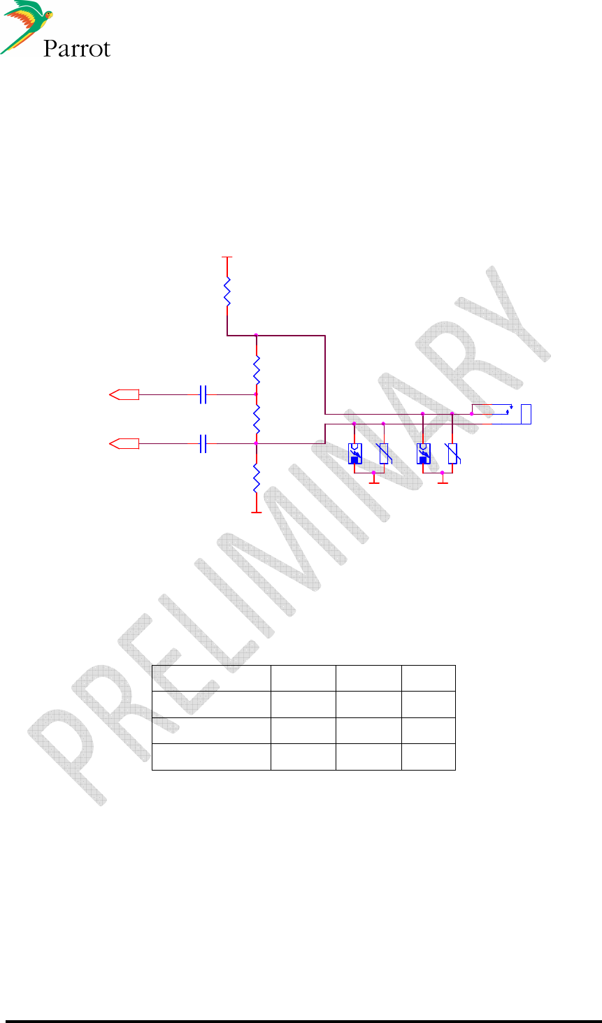
12.14.3 Microphone input
There are 2 types of microphones:
o
Passive microphones:
They are not amplified and have a typical sensitivity of -46dB r. 1dB/Pa.
o
VDA microphones :
Those microphones have the following characteristics:
o Sensitivity: 670mV/Pa or 300mV/Pa
o Operating voltage: 8V
o Serial resistor for power supply: 680Ω
12.14.3.1 Passive microphones
-
Eclat_0.12
12
GND
18V
GND
18V
-
Eclat_0.12
12
GND
J12
Jack_3_5mm
1
2
3
MIC_1P
MIC_1N
MIC_1_P
MIC_1_N 22u_10V_X5R
22u_10V_X5R
1K 1K
MIC_BIAS
FC6050 Connector
Microphone
Connector
DATASHEET Confidential Information 44/84
Ref:
EL
-
2009
-
009
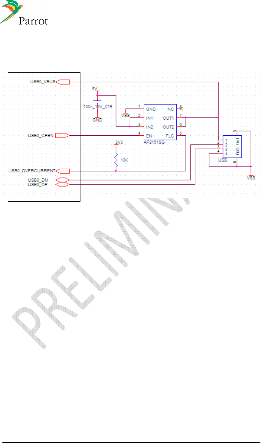
12.14.3.2 VDA microphones
The ADC gain must be set to 0dB by the Host SW via AT commands.
Furthermore the signal level of the microphone must be reduced by:
o 12dB with microphone with 670mV/Pa sensitivity
o 6dB with microphone with 300mV/Pa sensitivity
This can be done with a simple interface circuit. It is composed of a microphone bias circuit and a
signal reduction circuit
1u
2
1
4
0R
MIC1P
1u
VSS
MIC1N
8V_MIC
R715
680R
-
12
R2
18V
VSS
R1
-
12
18V
VSS
We use a voltage divider (R1, R2) to reduce the signal. It is dimensioned as follows:
R1 + R2 ≈ 15kΩ,
in order to keep the impedance of the load much higher than 680Ω.
- 20. Log (R2 / (R1 + R2)) = AdB,
in order to attenuate the signal by AdB.
We recommend using those resistor values for correct attenuation so that we can adjust easily
the tuning of SW audio parameter:
Sensitivity
300 670 mV/Pa
R1
6.8 11 kΩ
R2
6.8 3.6 kΩ
Attenuation
6 12.16 dB
There are no particular constraints on the layout of this circuit. Just make sure that the grounds of
the circuit above are connected to the ground of the module.
Also,
out_P
and
out_N
need to be laid out with the same precautions as with any differential
signal, i.e. placed side by side and with the shortest wires as possible. This is to avoid noise
issues.
DATASHEET Confidential Information 45/84
Ref:
EL
-
2009
-
009
12.14.4 USB
FC6050 Connector
USB Connector
DATASHEET Confidential Information 46/84
Ref:
EL
-
2009
-
009
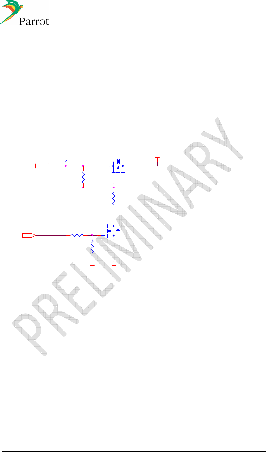
12.14.5 Supply FC6050B/W version
Recommendation on power management near the connector:
2 x 47uF capacitor
For decrease the current consumption, when FC6050B/W is not use, an input switch can be
added on the 3v3 power before the main connector.
Example:
nRESET
TSM2323
3
1
2
VSS
10K
VCC
nRESET
SWITCH ON/OFF
3V3
100K
1u_16V_X7R
TP1704
DMN2004
D2
G2
S2
4K7
47K
VSS

DATASHEET Confidential Information 47/84
Ref:
EL
-
2009
-
009
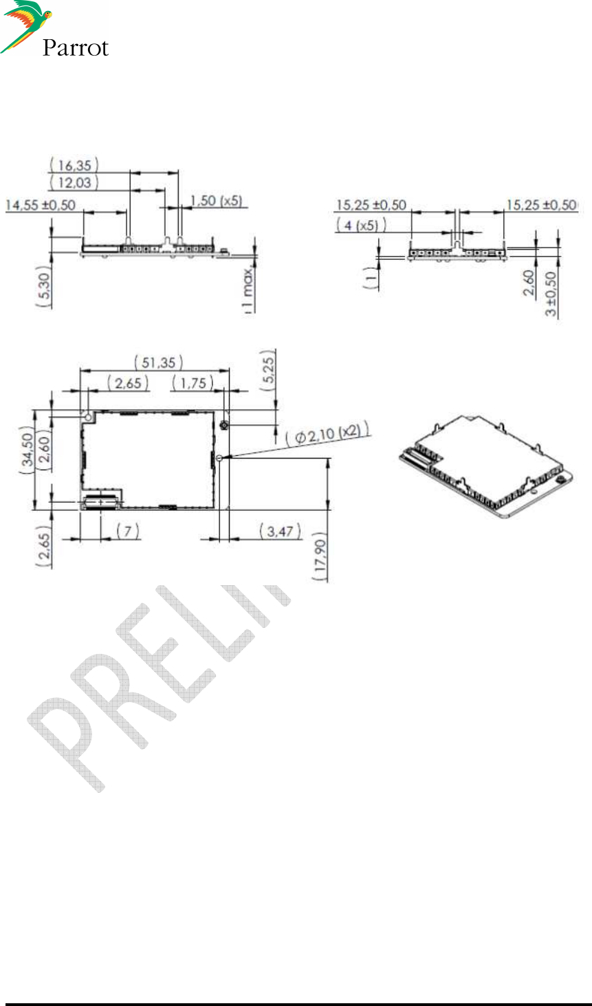
13 Mechanical specifications
The FC6050 modules will be available in two different mounting configurations, one
which mounts perpendicular to the host PCB (vertical) and one which mounts parallel to
the host PCB (horizontal).
The following chart describes the availability of the various versions of the FC6050B/W.
Module version Mounting
Bluetooth antenna Wi-Fi antenna
Internal external external
FC6050B horizontal
Yes Yes
vertical Yes Yes
FC6050W horizontal
Yes Yes Yes
vertical Yes Yes Yes
DATASHEET Confidential Information 48/84
Ref:
EL
-
2009
-
009
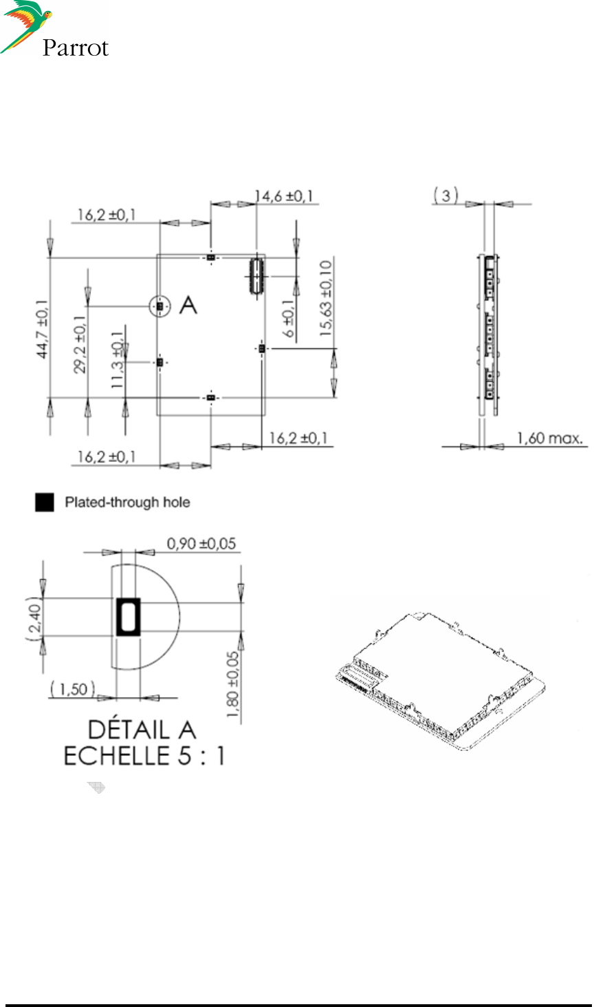
13.1
FC6050W Horizontal version
DATASHEET Confidential Information 49/84
Ref:
EL
-
2009
-
009
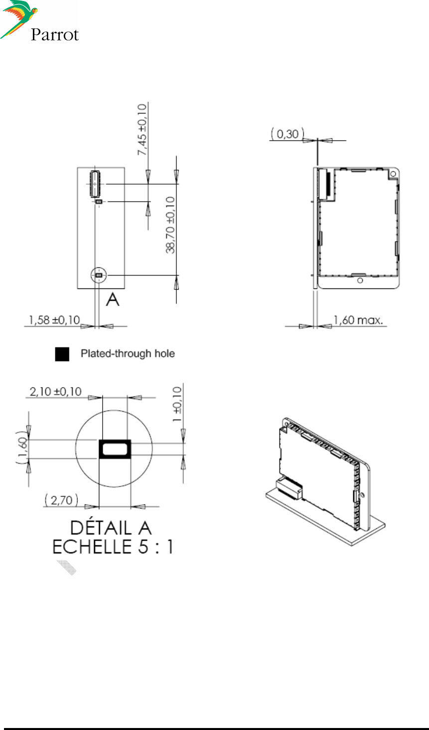
13.2
PCB footprint for FC6050W horizontal module
DATASHEET Confidential Information 50/84
Ref:
EL
-
2009
-
009
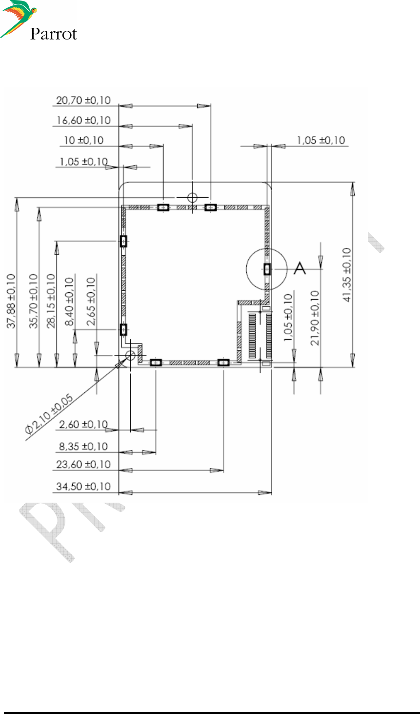
13.3
PCB footprint for FC6050W vertical module
DATASHEET Confidential Information 51/84
Ref:
EL
-
2009
-
009
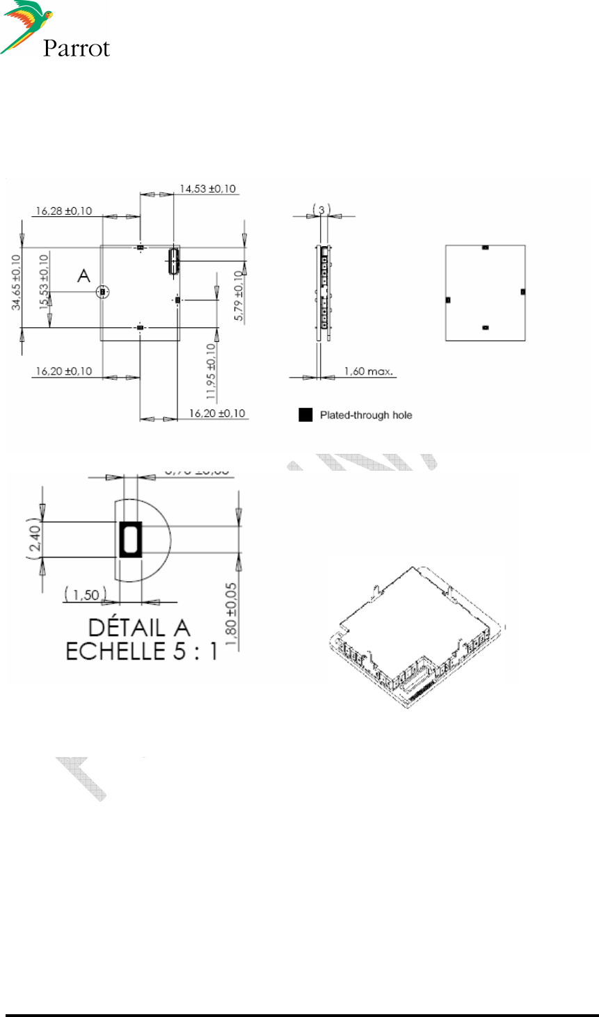
13.4
FC6050B PCB
DATASHEET Confidential Information 52/84
Ref:
EL
-
2009
-
009
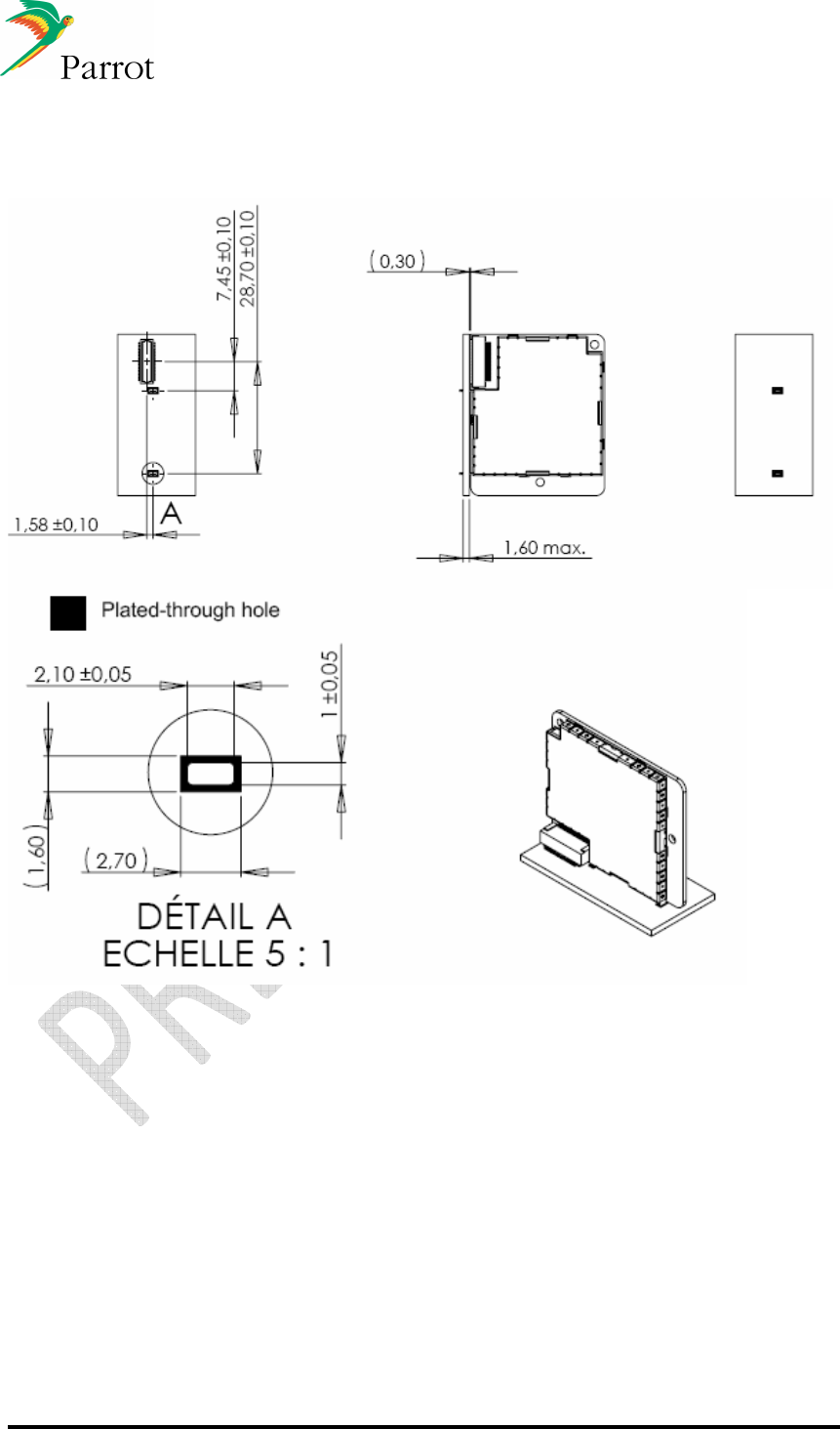
13.5
PCB footprint for FC6050B horizontal module
DATASHEET Confidential Information 53/84
Ref:
EL
-
2009
-
009
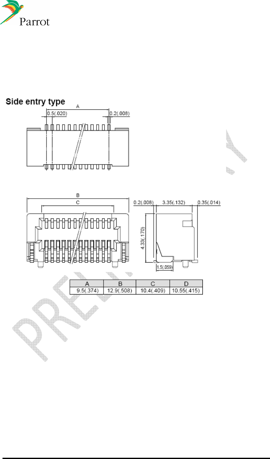
13.6
PCB footprint for FC6050B vertical module
DATASHEET Confidential Information 54/84
Ref:
EL
-
2009
-
009
13.7
Connectors specifications (FC6050 B/W)
13.7.1 Vertical connector specification
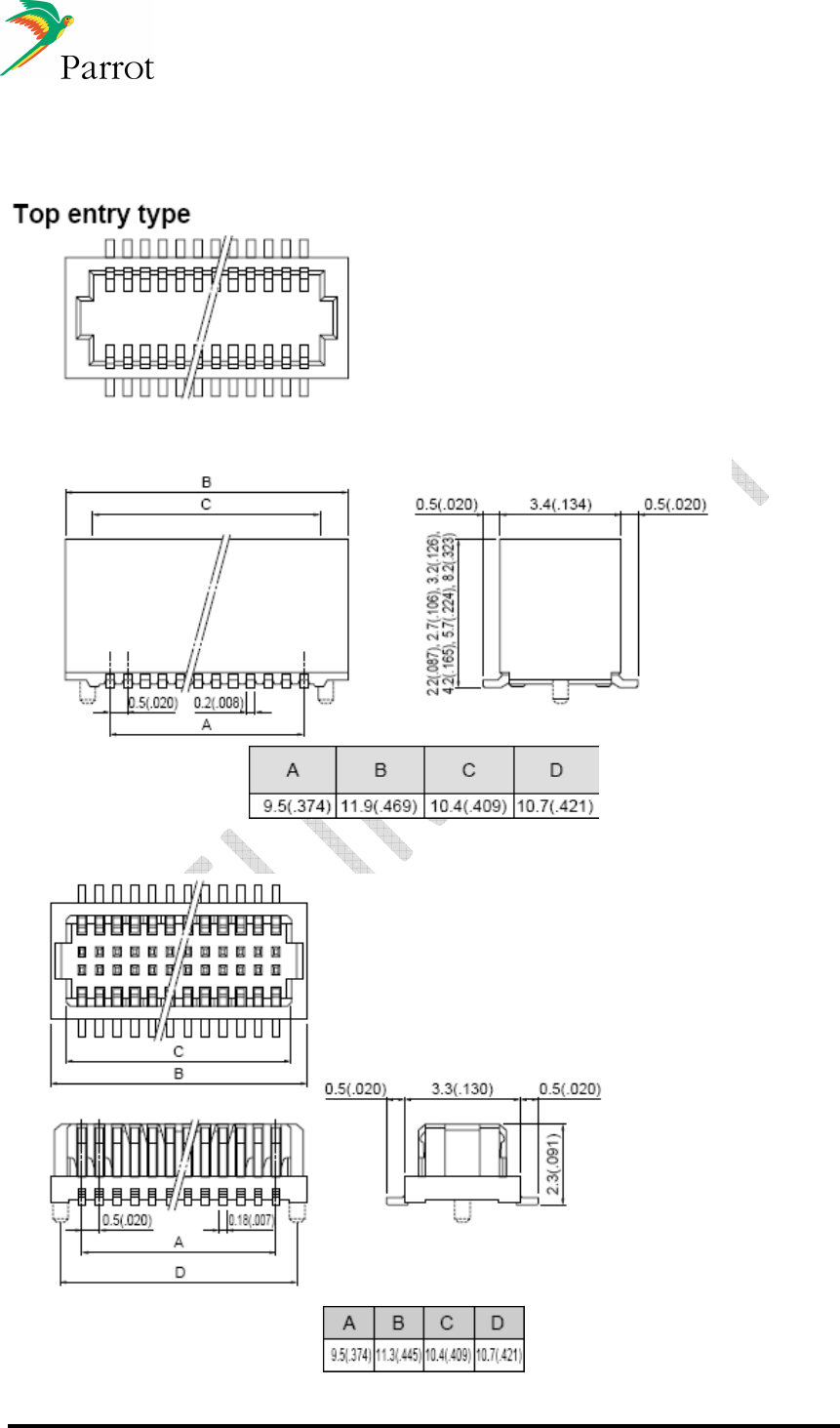
DATASHEET Confidential Information 55/84
Ref:
EL
-
2009
-
009
13.7.2 Horizontal connector specification
13.7.3 Host connectors specification
DATASHEET Confidential Information 56/84
Ref:
EL
-
2009
-
009
14 Connectivity use cases overview
14.1
Phone use cases
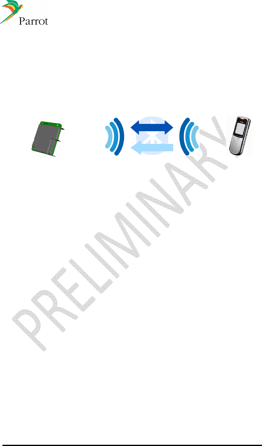
14.1.1 Head Unit (FC6050B/W) paired with Mobile phone
Handsfree telephony & Phonebook Synchronization
Hands Free Audio Gateway
Hands Free Device
Mobile Phone
Hands Free Telephony
Telephony
Phonebook
Phonebook synchro
FC6050B/W & Host
Connections Strategy
If the Host does not store the contact information from the last synchronization with the
phonebook, the information is available for the Host at the next Module start up.
Immediately after HFP connection (which is initiated with the last connected device), it is
possible to place an outgoing call if requested. Once HFP initialization has finished (end
of SLC/Extended SLC), the Module starts the best phonebook synchronization method
available for the paired and connected phone. The Module will alert the Host that the
phonebook synchronization is complete with new entries now available, and ready to be
displayed on the HMI.
If an incoming/outgoing call occurs during the phonebook synchronization process,
depending on the method of phonebook synchronization which is used, the process is
paused. Once the call is finished, the phonebook synchronization restarts from where it
has been stopped, and the call history is updated. This is transparent for the end user.
Calls Management
For incoming calls, the Caller ID data (received from phone via CLIP or CLCC) is sent to
the Host to be displayed on the HMI.
HFP indicators such as signal level, battery level and network provider are forwarded to
the Host to be displayed on the HMI. CIND/CIEV indicators or GSM AT Commands are
used for this purpose.
Service Continuity
This feature handles the audio management of a call when the module is powered
on/off:
-
When the module is powered on, the module automatically connects HFP to the
phone and establishes the communication ((e)SCO connection) through the speakers
during the SLC.

DATASHEET Confidential Information 57/84
Ref:
EL
-
2009
-
009
-
When the module is powered off, the module transfers the audio to the phone
((e)SCO disconnection) and disconnects the Bluetooth link.
This process ensures the Host to be immediately ready to start Handsfree usage.
Three way calling / multiple calls management
Once a call is established, if a second incoming call occurs, here is how the Host should
handle the HMI:
-
Green button: takes the second incoming call as active, and put the first one on hold.
Press green button again to switch between the two calls.
-
Red button: hangs up the active call and takes the second one as active.
Full 3-way calling management (and multiparty calls) is optimized with phones
supporting HFP1.5. Parrot supports up to 7 calls at the same time for conference call
purposes.
With phones supporting HFP1.0 only, there are gaps in the specification such as:
-
When the user manages the calls from the phone interface, the phone does not
always notify the Module.
-
When the distant party who is on hold hangs up from its side, the phone does not
always notify the Module.
DATASHEET Confidential Information 58/84
Ref:
EL
-
2009
-
009
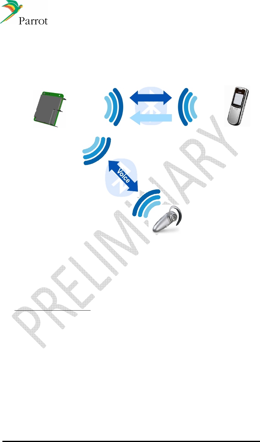
14.1.2 Head Unit (FC6050B/W) simultaneously connected to Mobile
phone and headset device
SCO link
Audio 8 kHz Mono
Car announcements
(Navigation,etc…)
and Communication privacy
Hands Free Audio Gateway
Hands Free Device
Hand Free Audio Gateway
Mobile Phone
Hands Free Telephony
Phonebook synchro
Telephony
Phonebook
FC6050B/W & Host
SCO forwarding feature (2 SCO)
The module is connected to a Headset and a phone at the same time. When requested
by the user, the Module is able to forward audio from the phone to the Headset.
Therefore, the communication is switched for privacy purpose. Two SCO channels are
opened by the Module.
Description of the behavior:
-
Incoming call:
o
Pick up from the HMI will pick up the call and establish one (e)SCO with the
phone and one with the Headset.
o
Hang up from the HMI will hang up the call and release the 2nd SCO.
-
Outgoing call:
o
Dialing from the HMI will place the call on the phone, and once the remote
party has picked up, one (e)SCO is established with the phone and one with
the Headset.
o
Hang up from the HMI will hang up the call and release the 2nd SCO.
A command is proposed on Parrot Module to handle the establishment of dual SCO,
depending on user need.
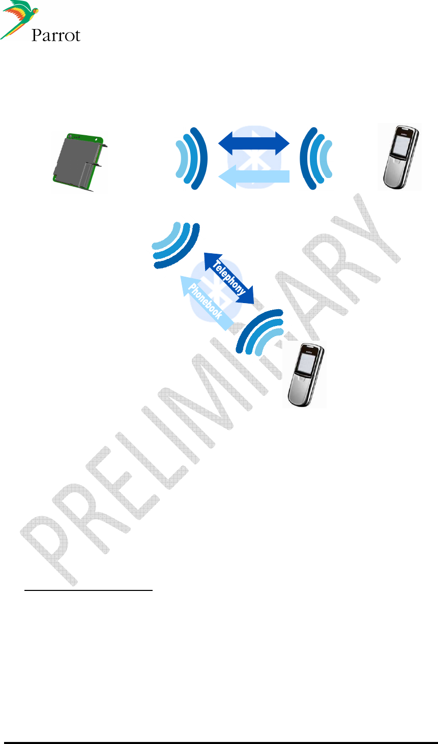
DATASHEET Confidential Information 59/84
Ref:
EL
-
2009
-
009
14.1.3 Head Unit paired with two Mobile phones
Establish and receiving call possible on two different mobile phones
Hands Free Audio Gateway
Hands Free Device
Mobile Phone
Hands Free Telephony
Telephony
Phonebook
Phonebook synchro
Mobile phone
Hands Free Audio Gateway
FC6050B/W & Host
Multi HFP Feature
Parrot has developed the “Multi - HFP” feature, which enables the Module to handle two
Handsfree connections at the same time. This use case is useful for people having two
mobile phones, or when two users are in the car.
The Module is running phonebook synchronization on both phones, and each phone has
its own phonebook available for the Host (phonebooks are not merged).
HFP indicators are available for each phone.
Description of the behavior:
-
First example:
two phones (P1 and P2) are connected to HFP service. The host can
start dialing on P1, hang up call then start outgoing call on P2.
-
Second example:
the phone receives incoming call P1 on Module. After the end of
the first call from P1 the phone P2 can receive incoming call.
The multi HFP does not manage the calls of two phones at the same time.
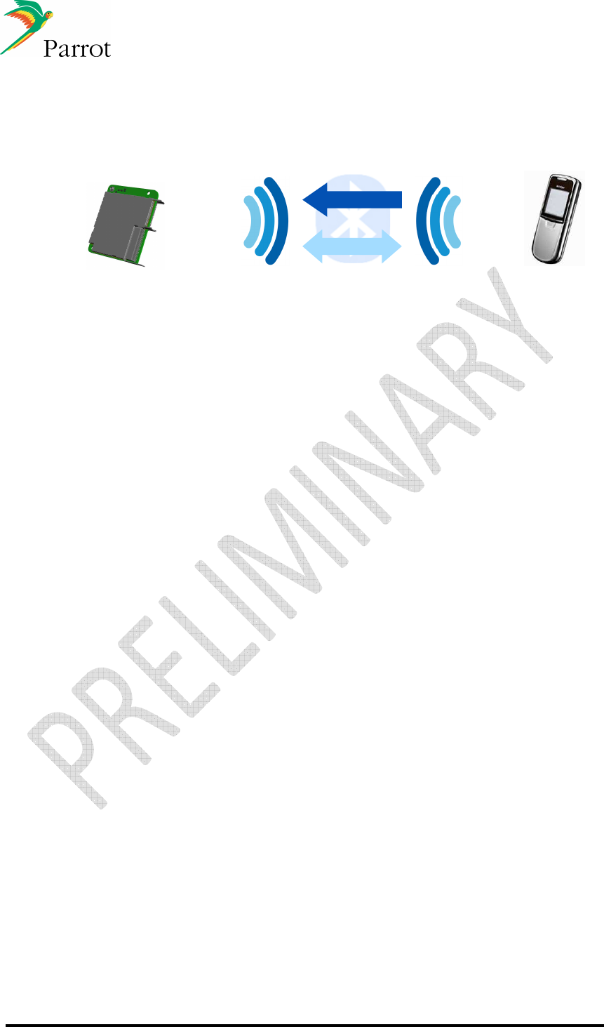
DATASHEET Confidential Information 60/84
Ref:
EL
-
2009
-
009
14.1.4 Audio Streaming and Handsfree working together
Audio Streaming from phone to Module (remotely controlled by the Module)
A2DP source
A2DP Sink
Mobile Phone or
Music Player
MP3 or SBC (A2DP & AVRC)
44 kHz stereo
Streaming
Control
FC6050B/W & Host
AVHFP Feature
Most phones now support both HFP and A2DP Source/AVRCP TG. The most difficult
case is to correctly handle the AVHFP Feature (dual use of A2DP/AVRCP and HFP).
As there is no specification release by the Bluetooth SIG explaining how this multi-profile
use case should operate, a whitepaper has been issued by the A/V Working Group
(“
Simultaneous Use of HFP, A2DP, And AVRCP Profiles
”).
Basically, the Whitepaper states that the phone should handle the streaming restart
management once the call is finished (this is the main concern today):
-
Incoming call:
the AG should handle the streaming management:
o
Pause the streaming upon indication of incoming call.
o
Send to the HF the indicators (CIEV Call setup)
o
Then, the HF picks up the call with ATA, communication/SCO is established
o
Once finished (from AG or HF), the AG should restart streaming from where it
has been paused.
-
Outgoing call from HF (ATD):
the AG should also handle this in the same manner.
Nevertheless, most phones do not correctly implement the Whitepaper, and the
streaming does not always restart after the call. Parrot has developed a strategy that
automatically relaunches streaming in this case.

DATASHEET Confidential Information 61/84
Ref:
EL
-
2009
-
009
Song information availability
According to the AVRCP version supported by the music player (can be a phone or a
Bluetooth Music player), the Host is updated with the following information in order to
update its HMI.
AVRCP TG 1.0 (Category 1 – Music Players):
-
Mandatory commands:
o
Play and stop.
-
Optional Features:
o
Enhanced control: Next, Previous, Pause, FF, FW (most of the
phones/Players supporting AVRCP1.0 support those commands).
o
There are a lot of other features, but the phone/Bluetooth Music Players do
not implement these extended commands.
AVRCP CT 1.0 (Category 1 – Parrot Module):
-
At least one command of the specification is mandatory.
-
Parrot has decided to implement the full Player Control (events send to the phone):
o
Play, Pause, Stop, Next, Previous, Pause, FF, FW
AVRCP TG 1.3 (Category 1 – Music Players):
-
Mandatory commands:
o
Same as AVRCP TG 1.0.
-
Optional Features:
o
If the phone supports the Bluetooth SIG Vendor Unique Feature, only Title of
the Media is mandatory for Metadata. And Playback status and change of
current track shall be supported in this case.
o
Other important features for Metadata support are Name of the Artist, Name
of the Album, Genre...
AVRCP CT 1.3 (Category 2 – Parrot Module):
-
Mandatory commands:
o
Same as AVRCP CT 1.0.
-
Parrot optional features implemented:
o
Referring to the specification, all “List of Media Attributes” are supported to be
displayed on the car radio HMI.
According to the AVRCP version supported by the phone, the HMI should be
implemented with information provided by the Module: Player status / Metadata for the
current played song.
As member of AV Working Group, Parrot is involved with the development of those
specifications.
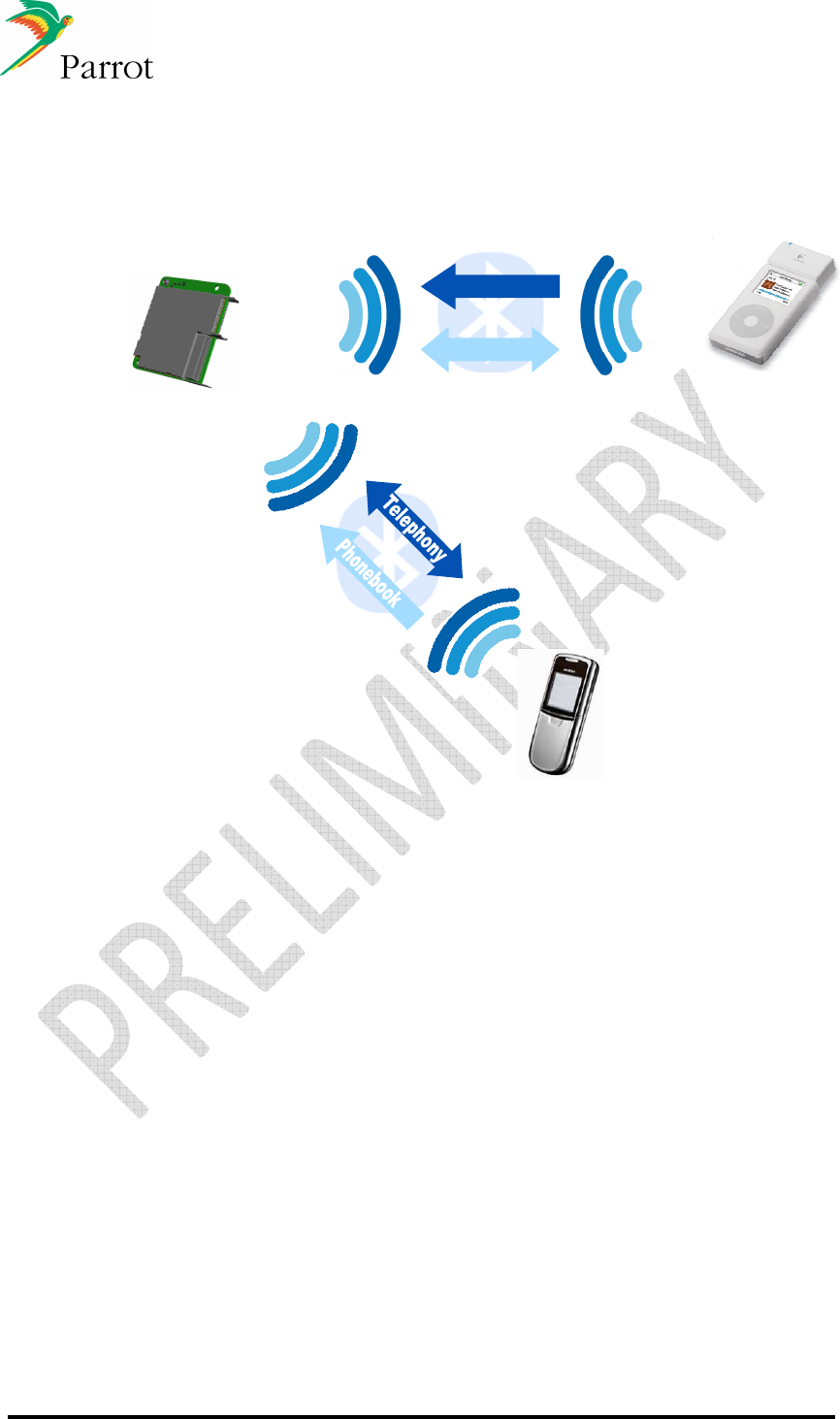
DATASHEET Confidential Information 62/84
Ref:
EL
-
2009
-
009
14.1.5 Head Unit (FC6050 B/W) paired with Mobile phone and Music
Player with Bluetooth dongle:
A2DP Source
A2DP Sink
Mobile Phone or
Music Player
MP3 or SBC (A2DP & AVRC
P
)
44
,1
kHz stereo
Streaming
Control
Mobile phone
FC6050B/W & Host
Connection Management
Parrot Module is able to maintain two Bluetooth connections: one HFP to a phone
(where the phonebook synchronization is running after connection) and the other one
with an A2DP SRC Music Player. From the Module point of view, there are two users
connected.
As stated with the Whitepaper, in this use case, the Module handles the AVHFP
because the A2DP SRC is not the connected phone. If the Bluetooth Music Player
supports AVRCP TG, Parrot alerts the HMI with Playback status and Metadata.
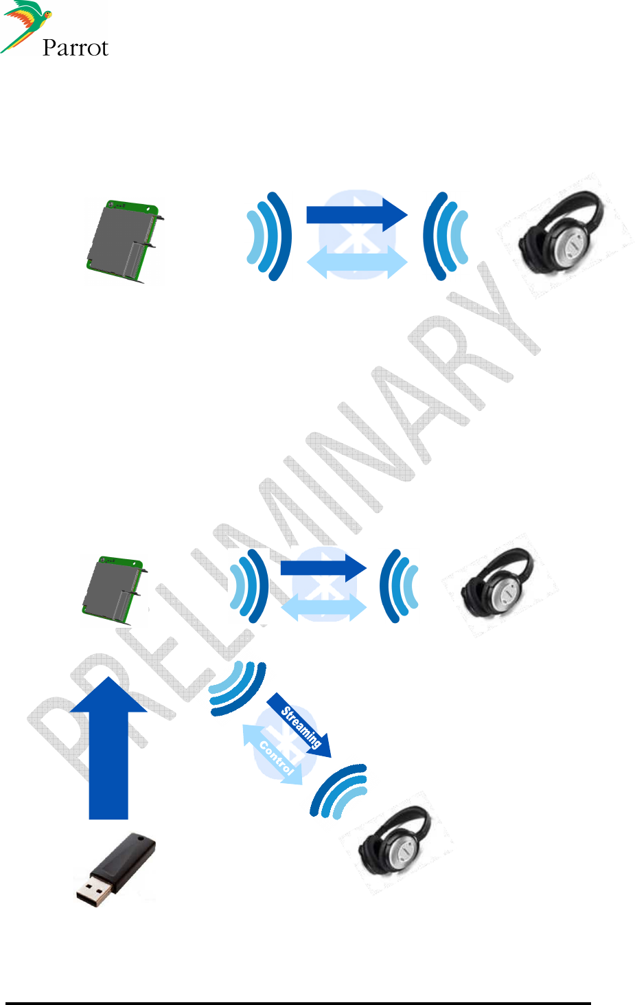
DATASHEET Confidential Information 63/84
Ref:
EL
-
2009
-
009
14.1.6 Head Unit paired with a stereo Headphone
Audio Streaming from Module to a stereo headphone
A2DP Sink
A2DP Source
Bluetooth
Headphones
MP3 or SBC (A2DP & AVRC
P
)
44,1 kHz stereo
Streaming
Control
FC6050B/W & Host
Parrot Module also embeds the A2DP SRC role, and then is able to play local music files
to a Sink device. Music file can be stored on a USB Flash Stick, or can be routed from
an iPod/iPhone connected to the FC6050 via USB to the A2DP SNK (headphones).
14.1.7 Head Unit paired with two stereo Headphones
Audio streaming from Module to two Stereo Headphones simultaneously
A2DP Sink
A2DP Source
Bluetooth
Headphones
MP3 or SBC (A2DP & AVRC
P
)
44,1 kHz stereo
Streaming
Control
Bluetooth
Headphones
A2DP Sink
Music files
transfer
(In this configuration, Concertos library is needed)
FC6050B/W & Host
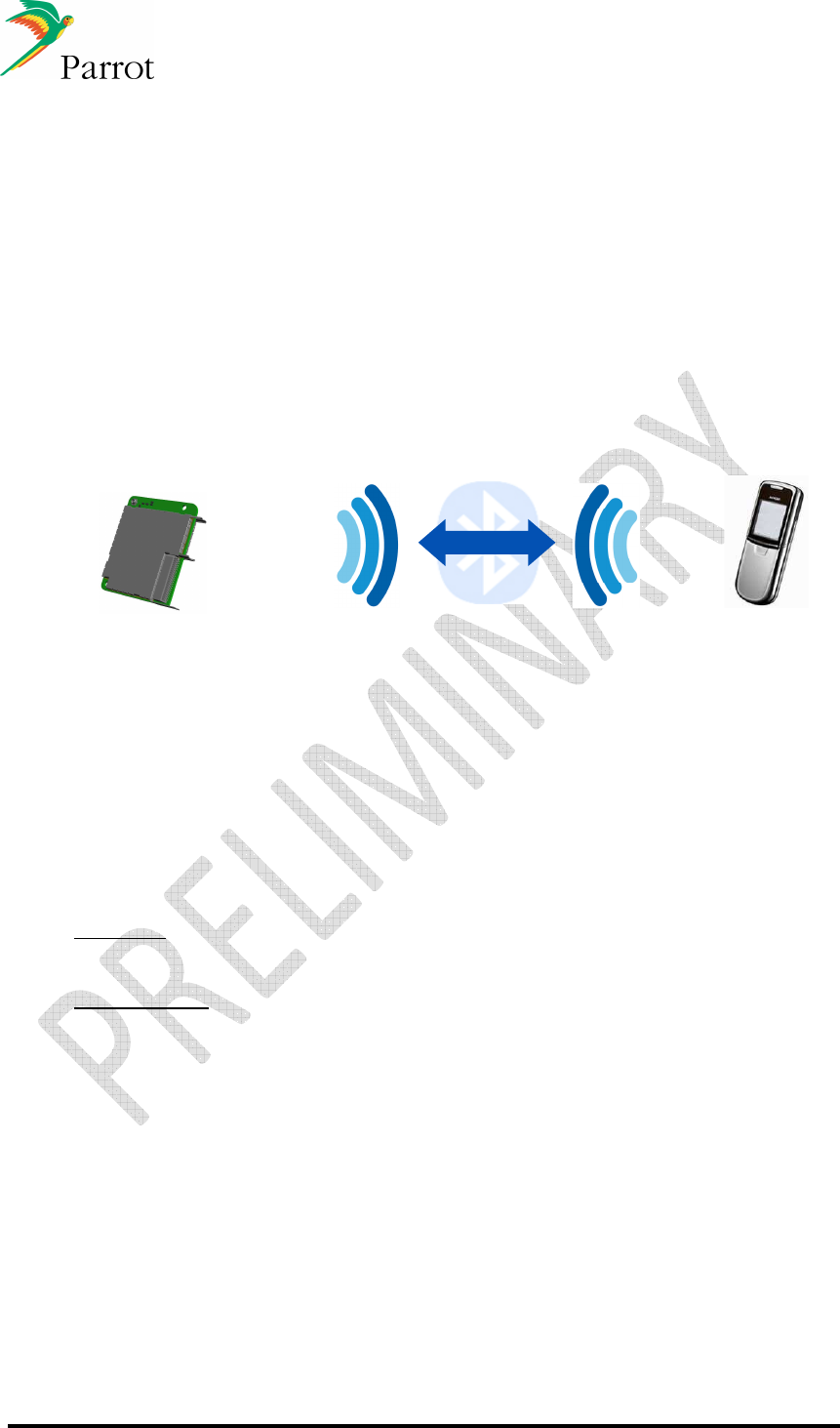
DATASHEET Confidential Information 64/84
Ref:
EL
-
2009
-
009
The Module manages the A2DP SRC role, and establishes two A2DP connections with
two A2DP Sinks. The audio file is streamed at the same time to the two headsets.
This use case is intended for streaming audio to rear seat passengers for entertainment
purposes.
14.1.8 Head Unit (FC6050 B/W) paired with Mobile phone: Data
transfer
Dial Up Networking (DUN): The Head Unit (FC6050 B/W) acts as data terminal with a
connected gateway device, typically a mobile phone. This allows the host to have
access to internet data via the FC6050 B/W.
DUN
Gateway
Data Terminal
Device
Mobile Phone
Data exchange
Data flow
FC6050B/W & Host
Multi Profile Use
Parrot handles multiple Bluetooth connections. On the same device, it is possible to set
up both an HFP and a DUN connection.
According to the various Bluetooth implementations on phones, here is the description of
what is possible (given no phone limitations):
-
DUN only:
o
In this case, the phone acts as a Gateway and the Module forwards the data
to the Host (Data Terminal).
-
HFP and DUN:
o
If an incoming call occurs during the data transfer, there are three phone-
dependent behaviors:
The call is established and data transfer continues without affecting
bandwidth.
The call is established and data transfer is stopped (AG gives priority
to HFP feature).
The remote caller reaches the voicemail of the connected phone
(phone limitation).
o
If an outgoing call is requested by the user, the behaviors above also apply.
These behaviors are described, phone by phone, in the Parrot Bluetooth Compatibility Matrix with all
tested phones.
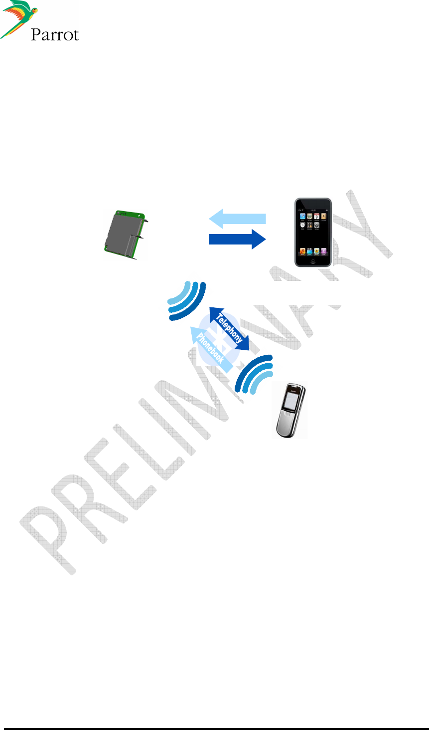
DATASHEET Confidential Information 65/84
Ref:
EL
-
2009
-
009
14.2
USB/iPod Use Cases
The use cases in this section require the use of Parrot CONCERTOS, which is Parrot’s
Multi-Source Media Player Software Library (optional). Concertos enables DISCO
playlist browsing on USB, iPod, SD and AVRCP1.4 devices and eases the switching
from one source to another.
14.2.1 Head Unit (FC6050 B/W) with an iPod connected through the
USB
In this configuration, the Apple IC is required on
the motherboard. Concertos library is needed
DISCO library is needed)
USB Host and HandFree Device
Mobile phone
Audio
Control
FC6050B/W & Host

DATASHEET Confidential Information 66/84
Ref:
EL
-
2009
-
009
iPod / iPhone Management
For iPod / iPhone management, the Module directly accesses the iPod/iPhone database via iAP.
Here are the browsing modes offered by the Module:
- Artist (For all devices, including USB Mass Storage)
- Album
- Genre
- Playlist
- Title
- Podcast (only for iPod/iPhone)
- Composer
- File System (only for USB)
- Flat File System (only for USB)
Alternately, for the phonebook, UTF8 is used to communicate this database to the Host
(independent of whether this is a USB or iPod database).
List of Compatible iPods
iPod Classic (3G), iPod Classic Photo (4G), iPod Classic Video (5G), iPod Classic (6G),
iPod Mini (1G), iPod Nano (1G), iPod Nano (2G), iPod Nano (3G), iPod Nano (4G),
iPod Touch (1G), iPod Touch (2G), iPhone, iPhone (3G).
14.2.2 IPod & iPhone use cases
The iPhone/iPhone3G can be used as a Bluetooth audio gateway and Music content at
the same time. In this case,
-
First, the user has to pair/connect their iPhone via Bluetooth to get the HFP features.
-
Once HFP connection has been established, they can connect their iPhone to the
dedicated iPod connector, and the Module handles the music browsing.
The user will have the Bluetooth HFP capacity and at the same time the possibility to
browse the iPod’s content.
More information about supported features are available in the Parrot Compatibility
Matrix.
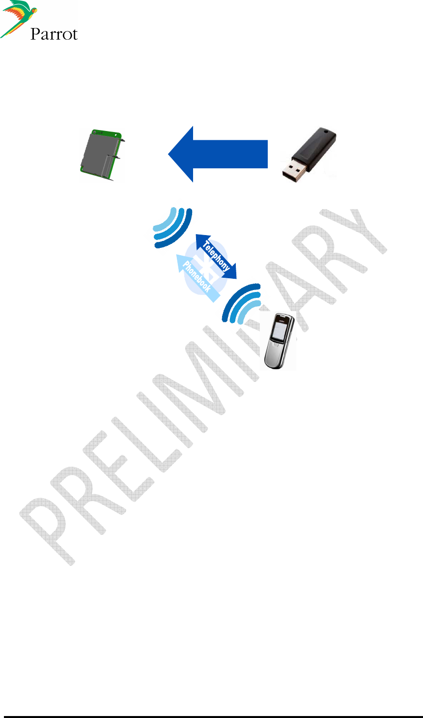
DATASHEET Confidential Information 67/84
Ref:
EL
-
2009
-
009
14.2.3 Head Unit (FC6050B/W) paired with a connected USB Mass
storage device
Music files
transfer
(In this configuration, Concertos library is needed)
USB Host and HandFree Device
Mobile phone
FC6050B/W & Host
Parrot Music Management
Once the USB flash stick is plugged in for the first time, the Module reads the USB stick content,
parses music files, and gives the Host the access to the file system. Once this first parsing is
finished, the Module re-parses music files, one by one, and builds the database using the
Metadata included in each file. The database is built according to this new parsing.
The Parrot Module provides the same set of commands for USB or iPods devices. The
implementation on the Host side is generic.
HFP and USB use at the same time
If a USB flash stick is plugged in while an HFP connection is already established with a phone,
this case is handled in two separate processes. Handsfree features are available while Concertos
is building the database in the background, without altering the Bluetooth link.
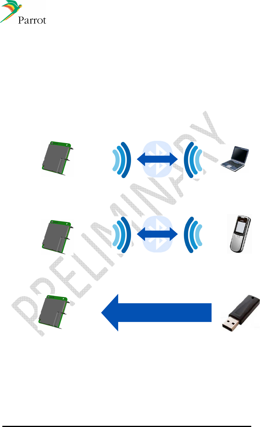
DATASHEET Confidential Information 68/84
Ref:
EL
-
2009
-
009
14.3
Head unit (FC6050
B/W) BT/USB/Wi-Fi software update
The firmware of Parrot modules can be updated in four different ways: by Bluetooth (when paired
with a Bluetooth-enabled laptop), by DUN, USB or UART.
The ability to update Parrot module software in the field is a very important feature of the
Parrot Module. This ensures better Bluetooth Compatibility with new phones, which are
continuously being released to the market. Some of these new phones need to have a
specific work-a-round when the Bluetooth specifications are not correctly implemented
on the phone (i.e. non-generic Bluetooth management).
Moreover, a major software update can include a new feature/profile (such as
AVRCP1.4 for instance) to give more compatibility or functionality to a car radio. This
software update can immediately be flashed (by Bluetooth, USB...) into your product
already out in the market.
User settings (paired devices, phonebooks...) are not erased during a software update.
Hands Free
update
Hands Free Device
Computer
Update by Bluetooth or UART
D
ata flow
FC6050B/W & Host
DUN
Gateway
Data Terminal
Device
Mobile Phone
Data flow
Update by B
luetooth
FC6050B/W & Host
USB Host
Data
transfer
(In this configuration, the update file is stored in
the USB stick)
FC6050B/W & Host
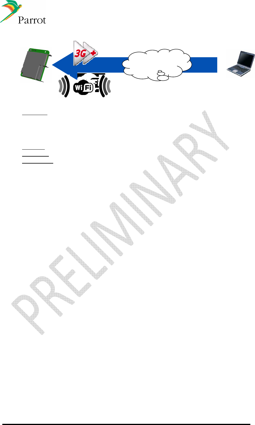
DATASHEET Confidential Information 69/84
Ref:
EL
-
2009
-
009
Remote Server
OR
Internet
FC6050B/W& Host
Methods available
-
Bluetooth
o
Via SPP
o
Via FTP
o
Via DUN (through a mobile phone connected to a server where the new
software is stored)
-
Via USB with a standard USB flash stick.
-
Via UART with a host CPU that sends the data
-
Via Internet: The FC6050B/W connects a server using either a 3G dongle or a Wi-Fi
connection (FC6050W). If an update is available on the server, the driver is then
prompted to launch the update process. (future method)
Secured software update mechanism
When the FC6050 software is updated, the new software is copied into the Module’s
flash memory but the previous software is not overwritten by this copy. During this
process, if an error occurs before the end of file transfer (Bluetooth disconnection, data
transfer stopped, USB Stick removed…), the Module will restart with the previous
software version.
The checksum of the new software is included into this new software. If the new file is
correctly written into the flash, when Module reboots, the new checksum is internally
calculated and compared to the checksum of this new software. If checksum are equal,
the new file will overwrite the previous one. During this process, if power supply is turned
off, the remaining data will continue to be written where it had been stopped at the next
boot.
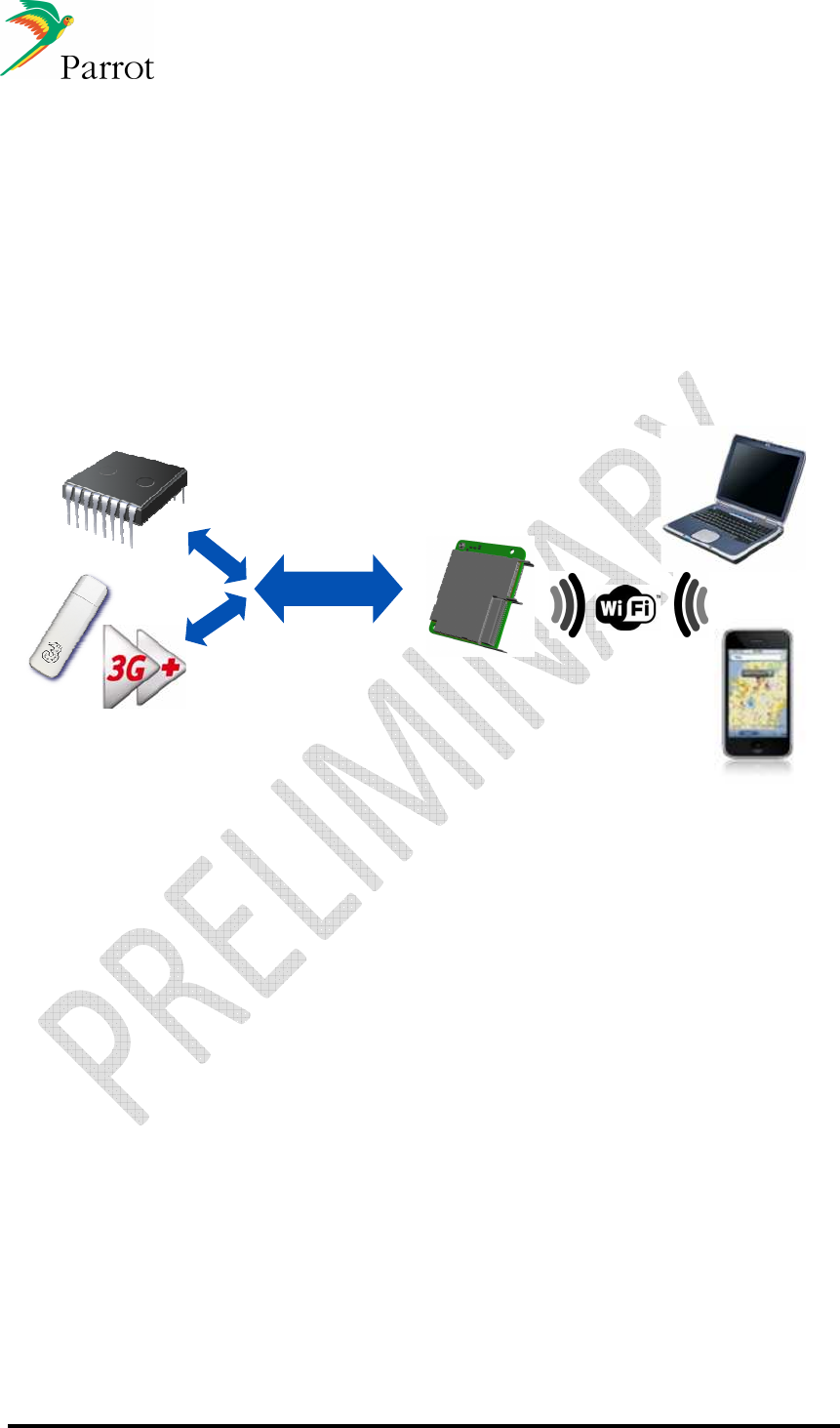
DATASHEET Confidential Information 70/84
Ref:
EL
-
2009
-
009
14.4
Wi-Fi use cases
The head unit (FC6050W) is connected in Wi-Fi with a phone or a computer. It can
connect to up to 8 Wi-Fi devices
14.4.1 Wi-Fi access point
14.4.1.1 Internet access in car through 3G+ USB dongle
3G
+
internet access
through USB
dongle
Data exchange
USB
Data Terminal
Device
USB2.0 HS
FC6050W
& Host
H
Ho
os
st
t
The module is connected to the internet through a 3G USB dongle. While the FC6050W
only has one high speed USB port, it can support an external USB HUB (it can be a
component soldered on host PWB or an external box) to support connection to both the
host and the dongle.
The module then re-routes the internet data exchange to the Host and/or provides it to
all the Wi-Fi connected devices (Laptop, netbook, iPhone, Google phone…)
internet access can also be made available to the host.
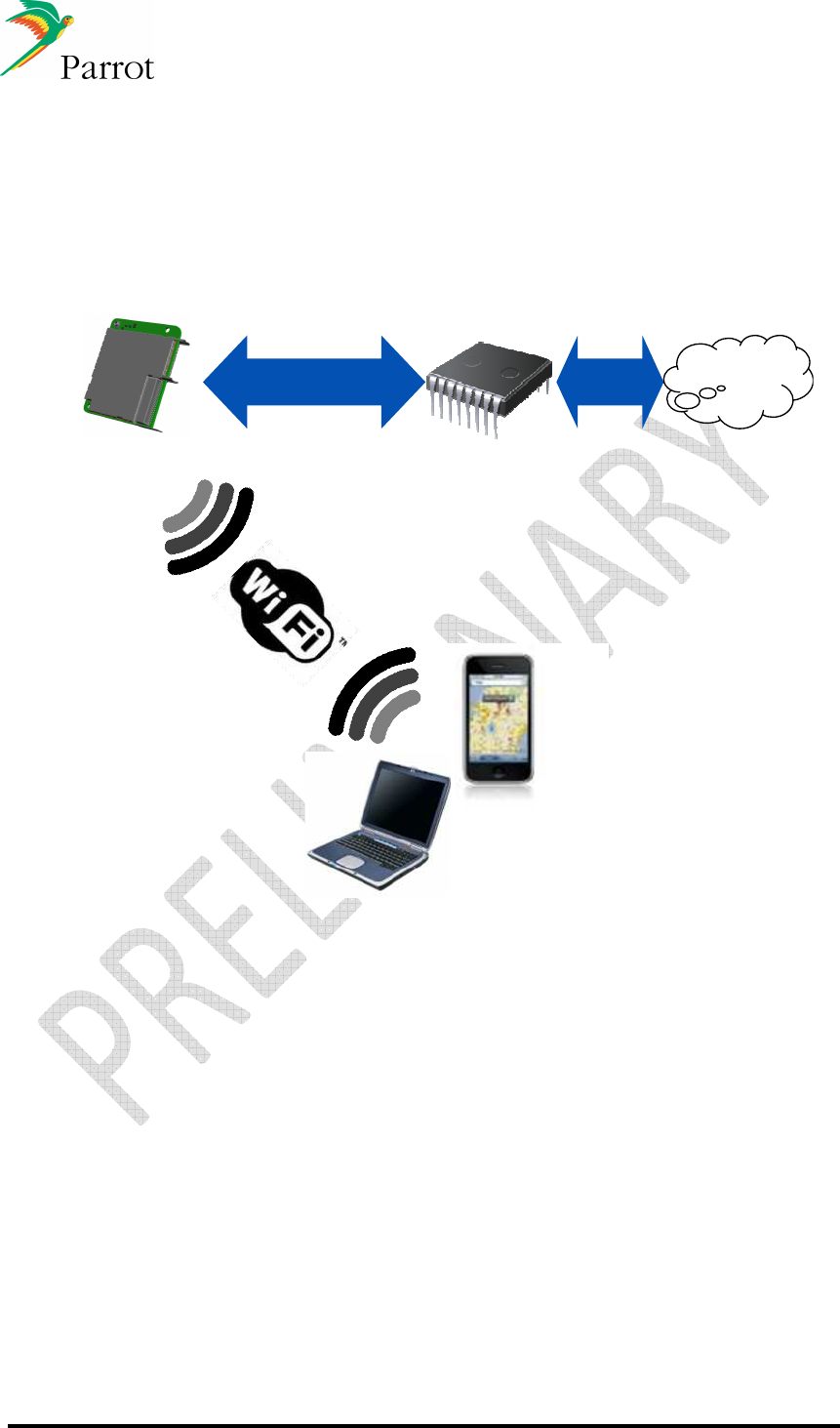
DATASHEET Confidential Information 71/84
Ref:
EL
-
2009
-
009
14.4.1.2 Internet access with 3G module connected to Host
processor
Data exchange
USB
Data Terminal
Device
USB2.0 HS
FC6050W
H
Ho
os
st
t
Up
to 8 devices
Tethering
Capable
Phone
Internet
The FC6050W module is connected to the internet through the host processor. The host
processor manages a 3G module which gives the access to the internet.
All data are transferred from the host processor to the FC6050W module through a high
speed USB bus, the FC6050W is then an access point for all WiFi devices that need an
internet connection.
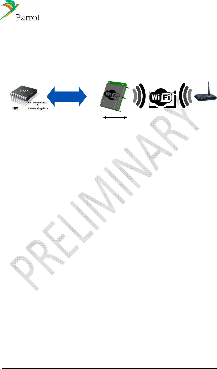
DATASHEET Confidential Information 72/84
Ref:
EL
-
2009
-
009
14.4.2 Wi-Fi station
FC6050W is Wi-Fi station; it connects to an access point and provides internet access to
the Host.
Wi-Fi
Station
USB Host
Host
Dongle
/
modem
NIC NIC
Host NIC
Wi-Fi
Access
Point
USB2.0 HS
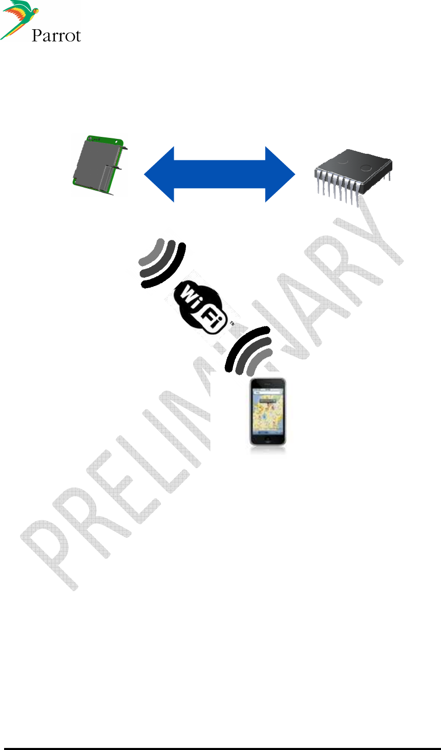
DATASHEET Confidential Information 73/84
Ref:
EL
-
2009
-
009
14.4.3 Internet access with mobile phone tethering
Data Terminal
Device
FC6050W
& Host
USB2.0 HS H
Ho
os
st
t
The FC6050W module is connected to the internet through a 3G mobile phone
supporting tethering over Wi-Fi.
The module then routes the internet data exchange and provides internet connection to
the host.
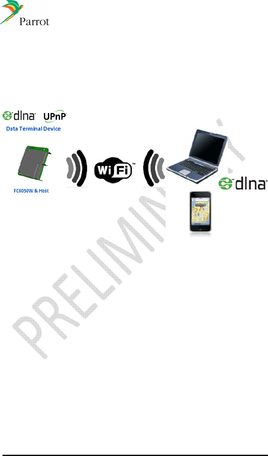
DATASHEET Confidential Information 74/84
Ref:
EL
-
2009
-
009
14.4.4 DLNA and UPNP
14.4.4.1 DLNA player
FC6050W is acting as a DLNA controller and renderer.
It is then possible to browse the media files available in the DLNA devices available in the
car and play them either on streaming or after download.
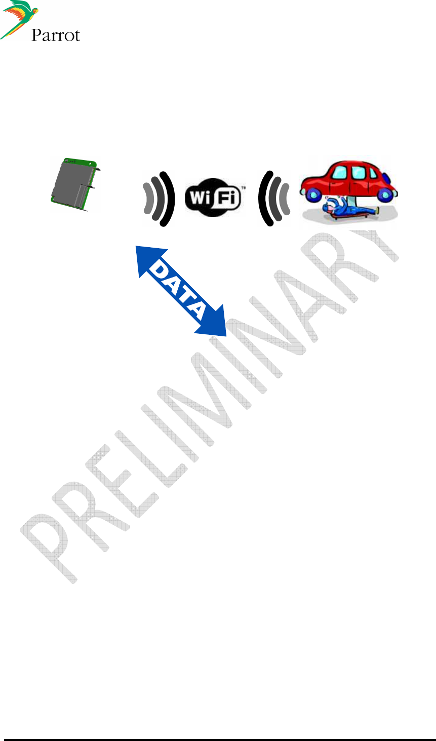
DATASHEET Confidential Information 75/84
Ref:
EL
-
2009
-
009
14.4.5 Future use cases
14.4.5.1 Diagnose vehicle trouble codes or perform software
updates at car dealership or car repair center
Car repair
Or
Car dealer
HOST Processor
(Diagnosis, …)
FC6050W
& Host
Connection with car dealer network
The car can be wirelessly connected to the car dealer diagnostic network at the dealership
service bay. New module software can then be downloaded, or diagnosis data can be collected
and sent to the car manufacturer for aggregate data analysis. The data can also be used to
convince the car owner to perform preventative maintenance before costly repairs are required.
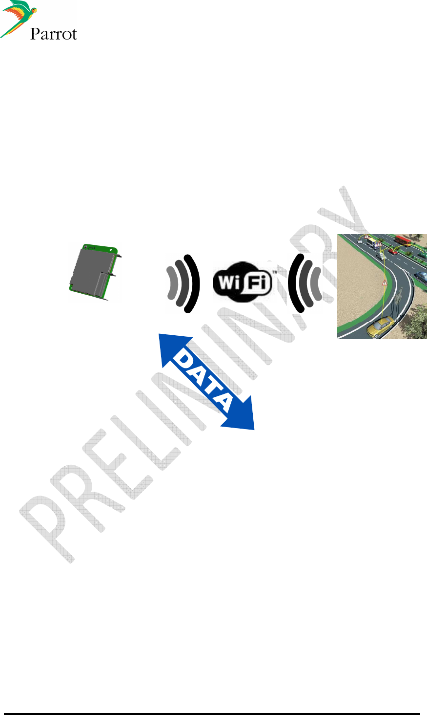
DATASHEET Confidential Information 76/84
Ref:
EL
-
2009
-
009
14.4.5.2 Vehicle 2 Vehicle communication
Organizations in the US and Europe are actively working to create specifications which
would enable vehicle to vehicle (V2V) and vehicle to infrastructure (V2I) communication.
This technology can enhance safety by alerting the vehicle of hazards on the road
beyond what is visible.
Based upon the final specifications, an alternate RF chip, supporting a different
frequency, may be required to support this use case.
Car
crash
or
Traffic jam
HOST Processor
(Alert driver,
switch on
warnings…)
FC6050W
& Host
Example: the car automatically provides information to car neighborhood that there is a car crash
or that there is a traffic jam ahead.
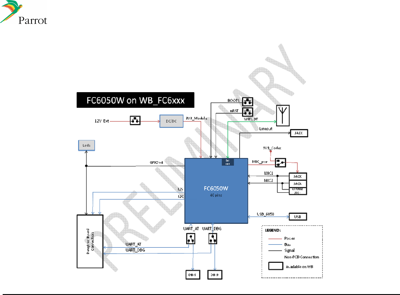
DATASHEET Confidential Information 77/84
Ref:
EL
-
2009
-
009
15 Workbench
This section describes how to use FC6050 with the WB-FC6xxx_Hw02
15.1
Bloc Diagram
This diagram show all interfaces available on WB-FC6xxx to communicate with FC6050W Module
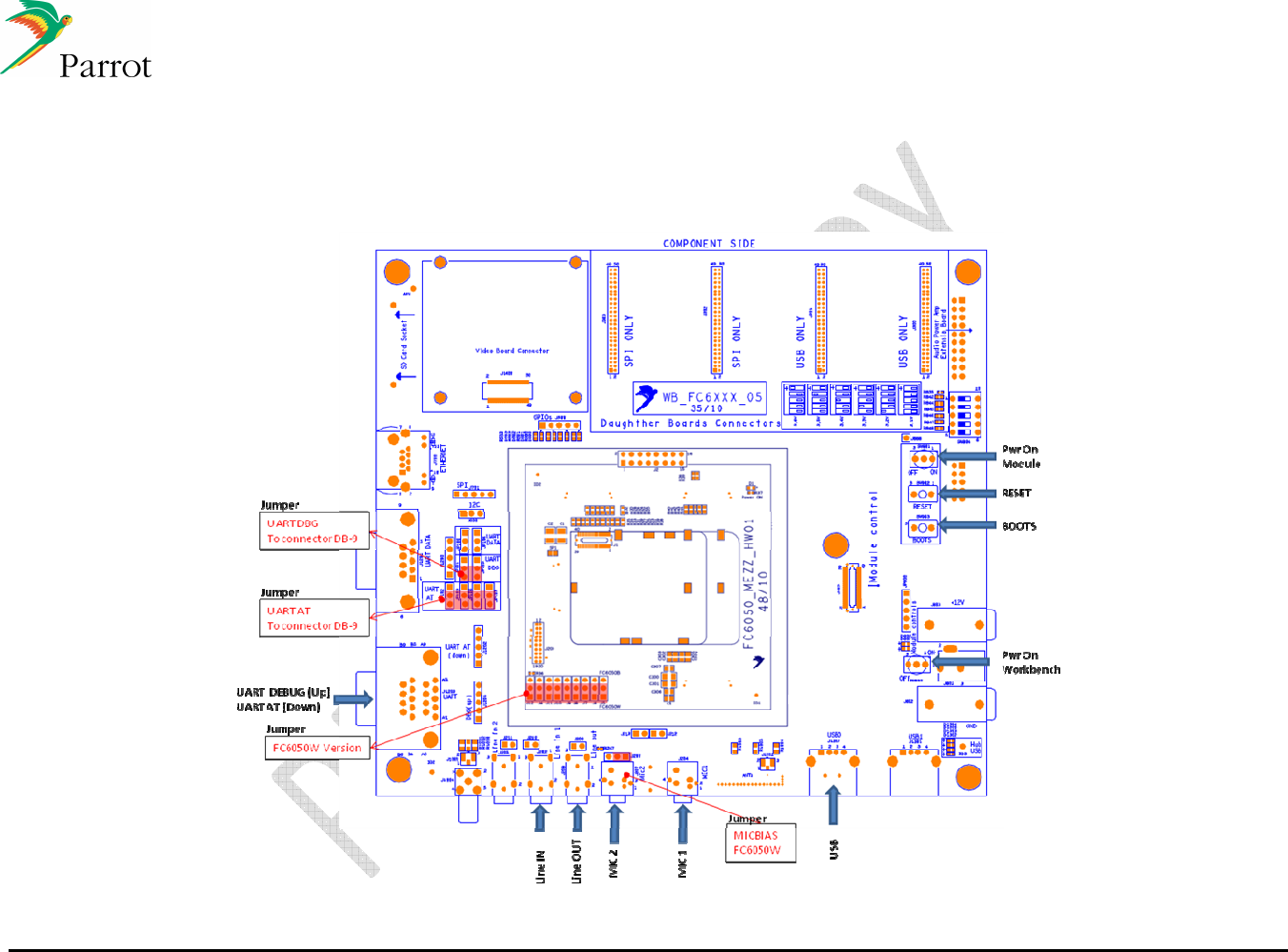
DATASHEET Confidential Information 78/84
Ref:
EL
-
2009
-
009
15.2
Connection & Jumpers Settings
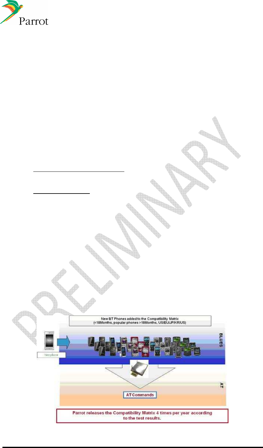
DATASHEET Confidential Information 79/84
Ref:
EL
-
2009
-
009
16 Interoperability management during mass production
One of the key benefits of implementing a Parrot solution is knowing the system will
have the same high level of compatibility Parrot is known for. In order to maintain the
highest level of interoperability, Parrot has set up the following process:
- Parrot procures almost all available mobile telephones which are each individually
tested.
- Local testing is done to account for variations in different carrier networks;
Europe, USA, China, Japan & Korea
- A software team of 8 engineers focuses on the development of new Bluetooth
profiles
- A dedicated software bug tracking system is used to allow testers around the
world to access test results
- A dedicated software development team is available for debugging, as required
- Automated test methods which allow unmanned testing of AT Command
interaction around the clock
There are two categories of phones used in testing:
1. Pilot phones (approved phones): Pilot phones are tested using the tier 1 product.
This testing is done by the carmaker or Tier1. This usually includes 10 to 20
phones per region, depending on the market.
2. Compatible Phones: Compatibility Phone testing is done at the Parrot module
level with approximately 500 phones per year worldwide.
Approved phones are typically highlighted by the tier 1 customer in their marketing
material and customer-facing communication as examples of phones which exhibit
highly compatible features. Compatible phones may include the “pilot phones” and are
published in the “compatibility matrix” issued four times per year.
The following sections are intended to give you further insight pertaining to the dedicated
process.
16.1
Blues interoperability testing (compatible phones)
•
Compatibility testing (done continually):
Compatibility testing is done continually to verify interoperability with the Parrot Blues
software. This testing is done in the US, Europe, Japan, Korea and China. Phones are
targeted for testing according to the following criteria;
•
All phones that are less than 18 months old
•
All popular phones (even if they are older than 18 months old)
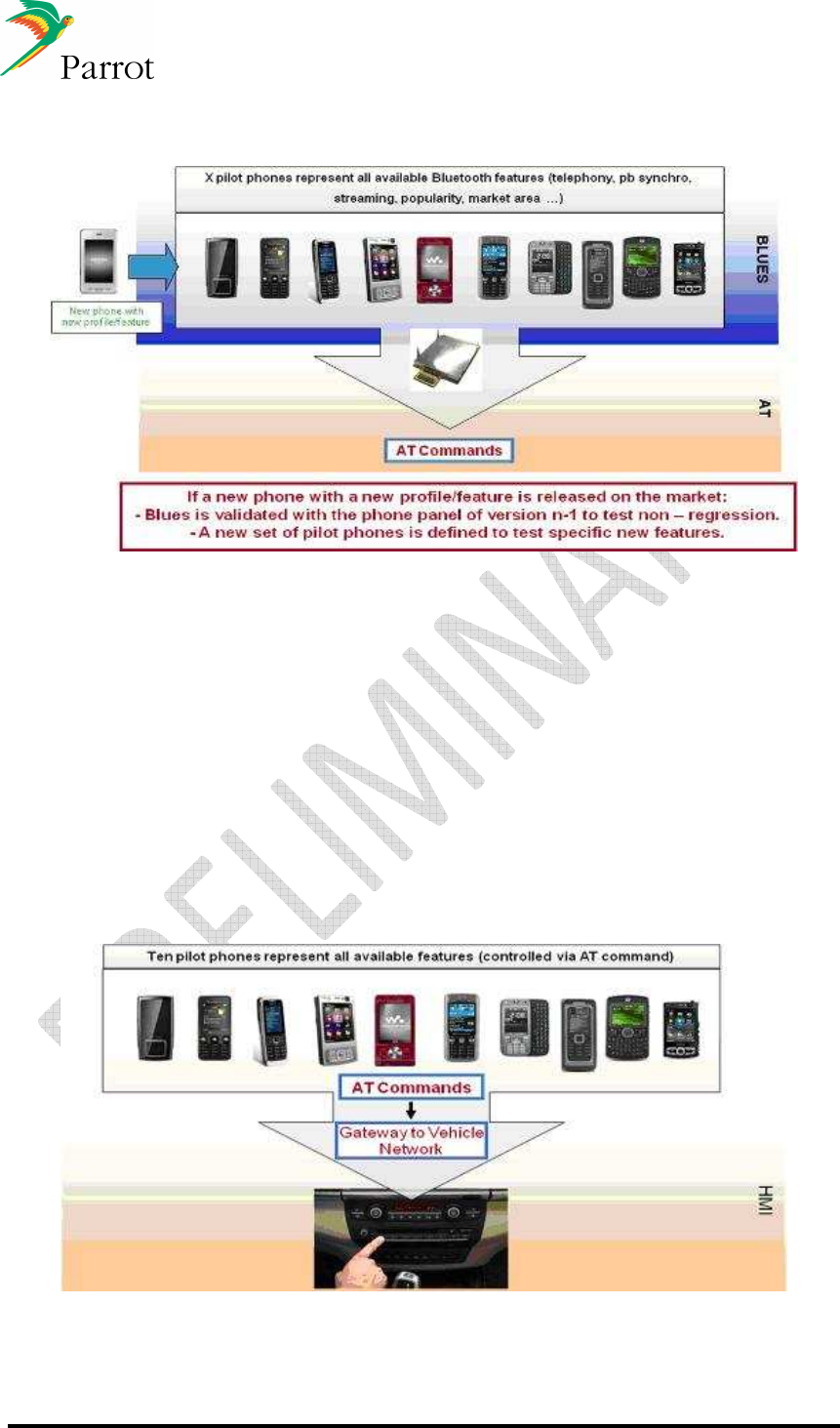
DATASHEET Confidential Information 80/84
Ref:
EL
-
2009
-
009
•
Pilot phone testing process for new BLUES releases (done per release):
16.2
Pilot phone testing of the gateway (Final product)
All phones tested during the Compatibility Testing process described above don’t need
to be retested on the final tier 1 product (gateway). A set of pilot phones, generally
around 10, are selected based on the set of features used in the product and phones
which support those features. If this set of pilot phones work properly with the gateway,
the HMI can be considered successfully validated for all phones with the same result
found in Parrot’s compatibility matrix.
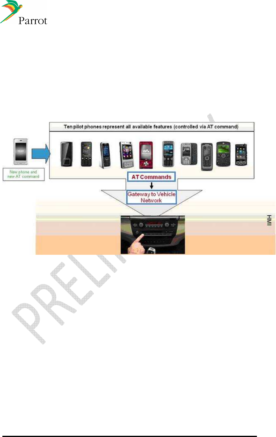
DATASHEET Confidential Information 81/84
Ref:
EL
-
2009
-
009
The following steps are required to complete the pilot phone testing of the gateway:
•
The customer will provide the set of AT commands they have implemented to control
the HMI and communicate with the Parrot software (or module).
•
The customer will also provide flow charts showing how the AT commands are
implemented according to planned use cases.
•
After review of the AT Command flow charts, Parrot will provide the list of pilot
phones that support the Gateway features and thus generate all AT commands and
events used in the HMI through the Gateway.
If new features are added later and a new AT command is needed, the pilot phone
testing of the gateway should be repeated with a new set of pilot phones that exercise
that new AT command:
The pilot phones testing is the responsibility of the tier 1 or the car maker using phones
approved by Parrot according to the steps described above.

DATASHEET Confidential Information 82/84
Ref:
EL
-
2009
-
009
17 Approval / Certifications
17.1
Bluetooth 3.0+HS qualification
17.2
Wi-Fi qualification
17.3
EMC certification
17.4
RoHS declaration.
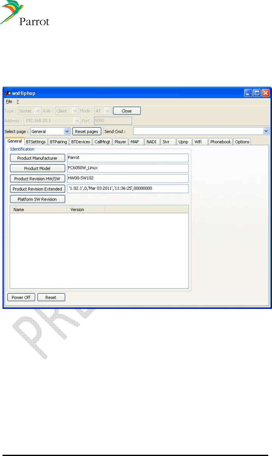
DATASHEET Confidential Information 83/84
Ref:
EL
-
2009
-
009
18 Communicate with FC6050 from PC: WxHipHop
For development purpose, WxHipHop is a windows-based software that gives the
possibility to send and read the AT commands used by the FC6050 from a PC.

DATASHEET Confidential Information 84/84
Ref:
EL
-
2009
-
009
19 FCC and IC Requirements for module application
FCC ID: RKXFC6050W
IC : 5119A-FC6050W
In accordance with FCC Part 15, the FC6050W is listed as a limited Modular Transmitter device.
USA – User information
This intends to inform how to specify the FCC ID of our module “FC6050W” on the product. Based on
the Public Notice from FCC, the host device should have a label which indicates that it contains our
module. The label should use wording such as: “Contains FCC ID: RKXFC6050W”
Any similar wording that expresses the same meaning may be used.
The label of the host device should also include the below FCC Statement. When it is not possible,
this information should be included in the User Manual of the host device.
“This device complies with part 15 of the FCC rules. Operation is subject to the following two
conditions.
(1) This device may not cause harmful interference
(2) this device must accept any interference received, including interference that may cause
undesired operation.
Caution: Changes or modifications not expressly approved by the party responsible for compliance
could void the user’s authority to operate the equipment.
Canada – User information
This intends to inform how to specify the IC ID of our module “FC6050W” on the product. According
to Canadian standards “RSS 210” and “RSS Gen” , the host device should have a label which indicates
that it contains our module. The label should use wording such as: “Contains IC ID: 519A-FC6050W
Any similar wording that expresses the same meaning may be used.
The label of the host device should also include the below IC Statement.
When it is not possible, this information should be included in the User Manual of the host device.
“Operation is subject to the following two conditions:
(1) this device may not cause interference, and
(2) this device must accept any interference, including interference that may cause undesired
operation of the device.”
Le présent appareil est conforme aux CNR d'Industrie Canada applicables aux appareils radio
exempts de licence. L'exploitation est autorisée aux deux conditions suivantes :
(1) l'appareil ne doit pas produire de brouillage, et
(2) l'utilisateur de l'appareil doit accepter tout brouillage radioélectrique subi, même si le brouillage
est susceptible d'en compromettre le fonctionnement.