PAX Technology IM300BW Encrypting PIN Pad User Manual
PAX Technology Limited Encrypting PIN Pad
User manual
Installation Manual
I
IM
M3
30
00
0
E
EN
NC
CR
RY
YP
PT
TE
ED
D
P
PI
IN
N
P
PA
AD
D
PAX TECHNOLOGY LIMITED

P
PA
AX
X
T
TE
EC
CH
HN
NO
OL
LO
OG
GY
Y
L
LI
IM
MI
IT
TE
ED
D
r
re
es
se
er
rv
ve
es
s
t
th
he
e
r
ri
ig
gh
ht
t
t
to
o
c
ch
ha
an
ng
ge
e
p
pr
ro
od
du
uc
ct
t
s
sp
pe
ec
ci
if
fi
ic
ca
at
ti
io
on
ns
s
w
w
i
i
t
t
h
h
o
o
u
u
t
t
p
p
r
r
i
i
o
o
r
r
n
n
o
o
t
t
i
i
f
f
i
i
c
c
a
a
t
t
i
i
o
o
n
n
.
.
P
PA
AX
X
T
TE
EC
CH
HN
NO
OL
LO
OG
GY
Y
L
LI
IM
MI
IT
TE
ED
D
Room 2416, 24F., Sun Hung Kai Centre, 30
Harbour Road, Wanchai, Hong Kong
Tel: +852-2588-8808 Fax: +852-2802-3300
Website: www.pax.com.hk
PAX TECHNOLOGY LIMITED
1
1
1.
.
P
Pr
ro
od
du
uc
ct
t
D
De
es
sc
cr
ri
ip
pt
ti
io
on
n
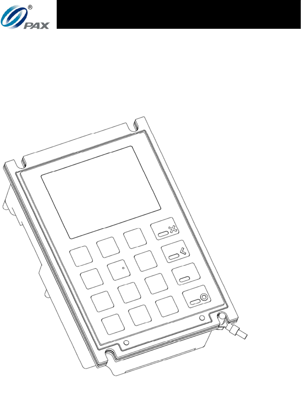
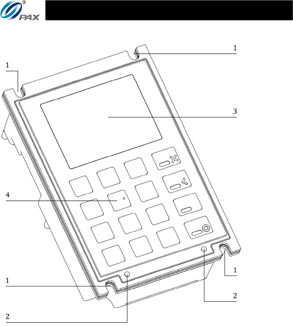
Figure 1: Front view
1. Mounting Points
2. Tamperproof Switches
3. Protective Lens & LCD Screen
4. Stainless Steel Keys
2
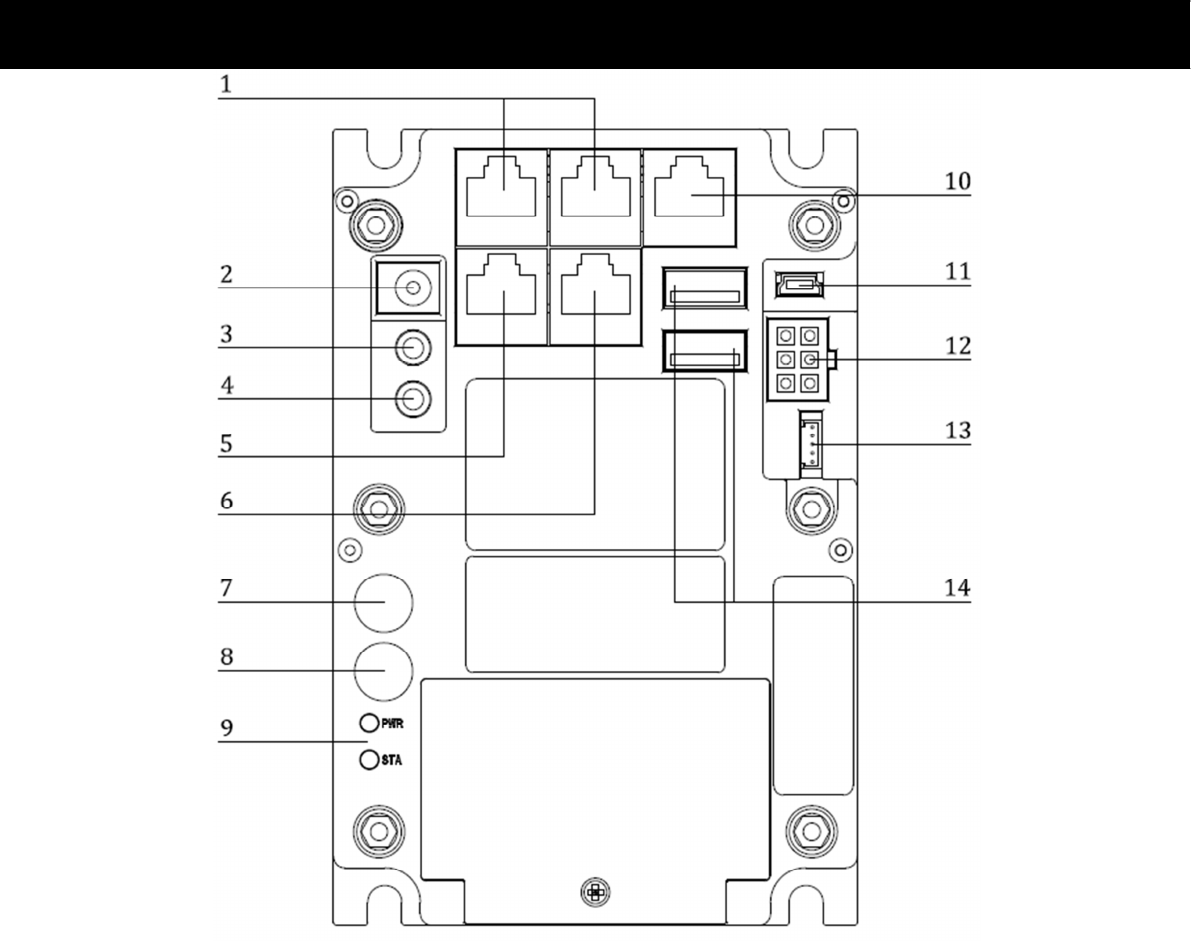
Figure 2: Back view
1. RJ45 ports (RS232)
2. 6.3mm DC power jack
(12VDC-Output)
3. Microphone jack
4. Earphone jack
5. Ethernet port
6. RJ45 port (RS232)
7. SMA connector
8. WIFI/BT antenna connector
9. LED indicators
10. RJ45 port (RS232)
11. USB 2.0 Mini-B
12. MDB port
13. Temperature control
(reserved)
14. USB 2.0 Type-A
PAX TECHNOLOGY LIMITED
3
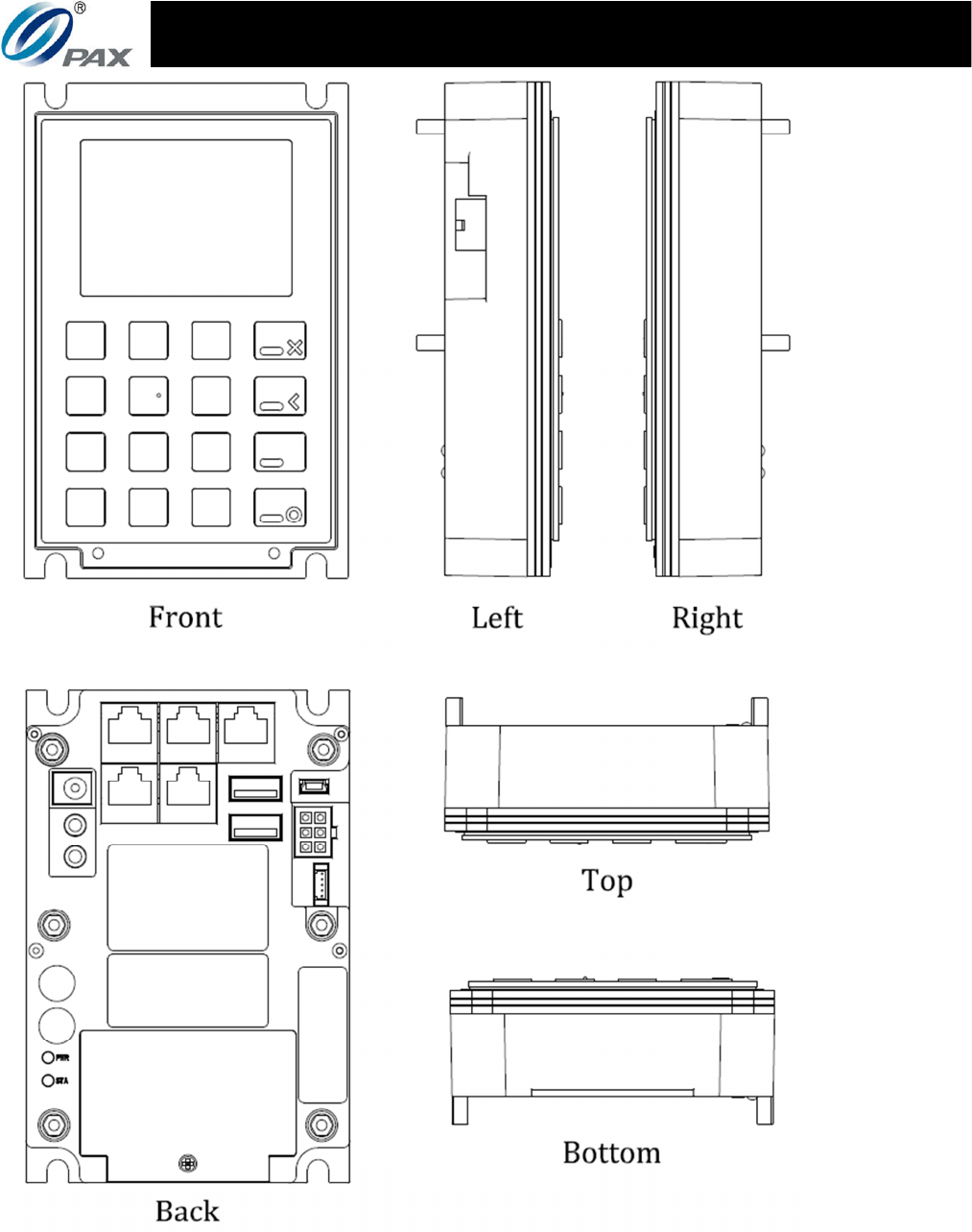
Figure 3: View from all angles
6
2
2.
.
I
In
ns
st
ta
al
ll
la
at
ti
io
on
n
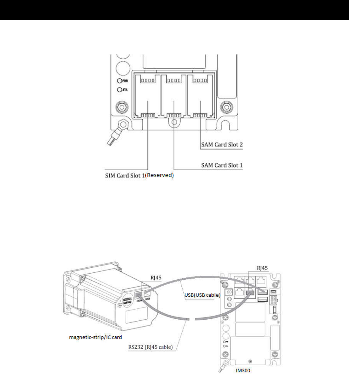
1) SAM& SIM Cards
Figure 4: SAM and SIM(Reserved)card mounts
Unscrew the SAM card cover to remove it. Open the mount
and insert the card into the slot with the contacts facing
downwards and the clipped corner of the card to the upper
right, then lock the mount with the card inside and replace the
cover.
2) Recommended Device Connection
Figure 5: Connecting the IM300 to amagnetic-strip/IC card reader
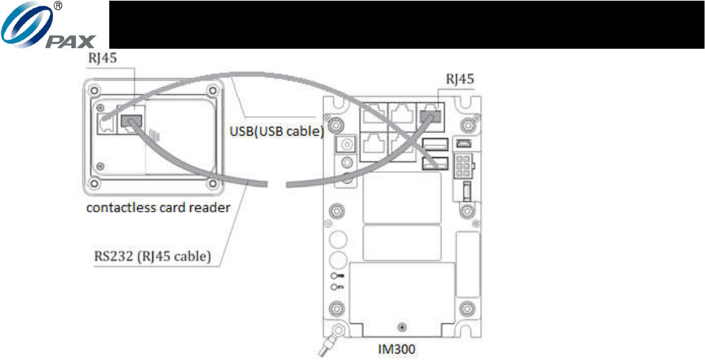
PAX TECHNOLOGY LIMITED
7
Figure 6: Connecting the IM300 to a contactless card reader
The IM300 can be connected to a magnetic-strip/IC card
reader(IM500 of PAX is recommended) as well as a contactless
card reader (IM700 of PAX is recommended) through the use
of RS232 serial ports using a RJ45 cable as indicated in Figure 5
and Figure 6. The IM300 both controls and powers the
magnetic-strip/IC card and contactless card reader. If the
IM300 is used to link to devices aside from the IM500 and
IM700, the user must first confirm that the software and
hardware for the connection is suitable.
3) This product needs to be installed in a professional way:
a) Antenna installation for WIFI/BT:
NO.8 SMA connector is for the WIFI/BT antenna connection.
The user must follow the antenna parameter if they want
install WIFI/BT antenna to IM300 :
Frequency:2.400 GHz ~ 2.497 GHz
Gain:2.400 GHz ~ 2.497 GHz 0dBi
Antenna radiation efficiency:2.400 GHz ~ 2.497 GHz >50%
Polarity:vertical
VSWR: 2.400 GHz ~ 2.497 GHz <2.0

6
Directivity:2.400 GHz ~ 2.497 GHz <5
Connector: SMA (Male & gold plated)
If the above parameters are satisfied, the user can use the
antenna that satisfies the condition with the IM300.
Note: WIFI/BT antenna information used for the test
collocation is as follow:
Brand name: GUOXU;
Model name: GX086S;
Antenna type: Monopole
Antenna Gain: 0 dBi
b) Special used for industrial and commercial purposes:
It should be sold to the dealers authorized by PAX and
installed by the professional person;
It should be used in the unattended machine and cannot
be available to average consumer because of its security
and applicability;
This device has got the PCI 5.X certification and is provided
with Anti-Remove function which means the necessity of
professional installation.
c) Other professional installation requirements:
NO.8 SMA connector is designed for the WIFI/BT antenna
connection. The user can connect the antenna to IM300
via the port. The antenna should be installed as high as
possible on the unattended machine.
Installation requires the special training that PAX can
provide including programming, access to keypad, field
strength measurements made and so on.
PAX TECHNOLOGY LIMITED
7
3
3.
.
I
In
ns
st
tr
ru
uc
ct
ti
io
on
ns
s
1) Switching the IM300 on and off
Switch on: Connect the IM300 to an appropriate power
terminal either via the power cable or the MDB
cable (make sure to have the appropriate voltages
and pinouts).
Switch off: Disconnect the IM300from whatever power
terminal it is connected to.
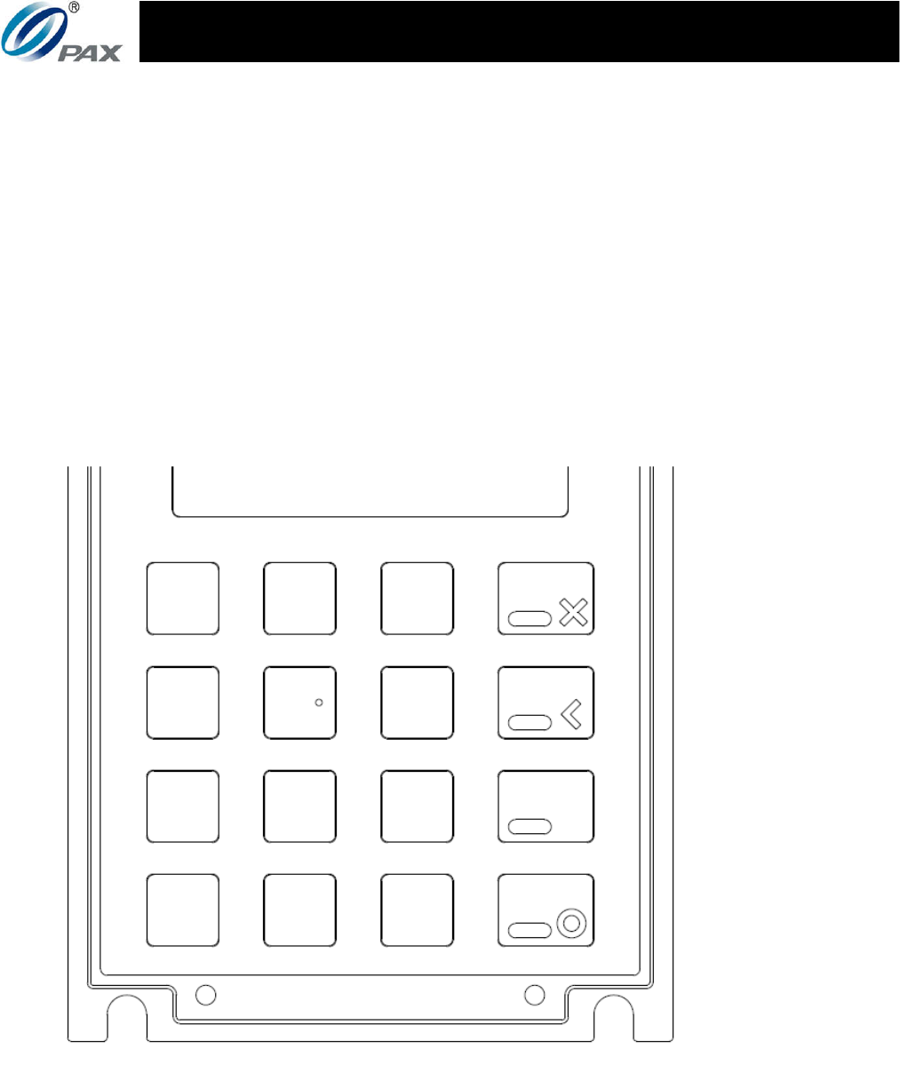
2) Using the Keypad
Figure 7: IM300 keypad
The IM300 contains a standard numeric keypad; 1 through 9
incrementing through three rows, with 0 being in the bottom

10
center fourth row (center-left in Figure 7 because of the
functional keys in the last column). The functional keys from
top to bottom are: cancel, clear, help, and enter. The two up
and down navigational keys are respectively on the bottom
center-right and the bottom far-left. Specific actions
performed by the keys are context specific should be intuitive
given whatever is shown on the screen.
4
4.
.
S
Sp
pe
ec
ci
if
fi
ic
ca
at
ti
io
on
ns
s
CPU: 1 GHz Application Processor
Operating System: Linux
Memory: 4Gb DDR3
4Gb NAND Flash
Display: 2.8" TFT color display
320 x 240 pixels
SAM Slots: 2 slots, ISO/IEC 7816
Peripheral Ports: 4 RS232 (RJ45)
1 Ethernet (RJ45, 100Mb/s)
2 USB 2.0 (USB Type-B)
1USB 2.0 (USB Mini-B)
1 MDB port
1 microphone jack
1 earphone jack
1 1.25mm 5 pin socket
WIFI: 2.4GHz 802.11 b/g/n
Bluetooth: Bluetooth V4.0
Battery: 1 Nickel button battery, 600mAh, 3.0V
Power Supply: Input: 9VDC~42VDC (MDB)
Output: 5VDC (USB2.0 Type-A) x 2
12VDC (RS232 via RJ45) x 2

PAX TECHNOLOGY LIMITED
9
Buzzer: ≥80dB
Operating Temperature: -20°C~70°C
-4°F ~158°F
Storage Temperature: -30°C~70°C
-22°F ~158°F
Relative Humidity: 5%~95% (without condensation)
Dimensions: 92mm x 33.8mm x 140mm
5
5.
.
M
Ma
ai
in
nt
te
en
na
an
nc
ce
e
a
an
nd
d
U
Us
sa
ag
ge
e
1) Do not damage any of the cables; if a cable becomes damaged,
immediately discontinue its use and seek a replacement.
2) Make sure the terminals the power or MDB cables connect to
provide the appropriate voltages at the proper pins.
3) Do not insert unknown materials into any port on the IM300,
this may cause serious damage to the device.
4) If the IM300 becomes defective, please contact a professional
technician for repairs instead of attempting them on your own.
5) The IM300 contains hardware tamper-proofing measures;
disassembly of the device will trigger the tamper circuits, at
which point it will have to be rearmed by qualified personnel
before the device is ready to resume operation.
6) When mounting the IM300 into its enclosure, ensure that the
tamperproof switches are fully depressed against the
mounting panel.
7) The IM300 is designed for outdoor use; however, during
normal use its surface should still be kept clear of dirt and
possible liquid contaminants.
8) While the IM300 is designed to resist ingress of dust and
liquids from the front face, it is not designed to resist
pressurized liquids such as water hoses. Keep the back of the
device away from dust and liquids as much as possible.

10
6
6.
.
F
FC
CC
C
C
Co
om
mp
pl
li
ia
an
nc
ce
e
S
St
ta
at
te
em
me
en
nt
t
This device complies with Part 15 of the FCC Rules. Operation is
subject to the following two conditions:
1) This device may not cause harmful interference, and
2) This device must accept any interference received, including
interference that may cause undesired operation.
FCC WARNING
This equipment has been tested and found to comply with the
limits for a Class B digital device, pursuant to Part 15 of the FCC
Rules. These limits are designed to provide reasonable protection
against harmful interference in a residential installation.
This equipment generates, uses and can radiate radio frequency
energy and, if not installed and used in accordance with the
instructions, may cause harmful interference to radio
communications.
However, there is no guarantee that interference will not occur in
a particular installation. If this equipment does cause harmful
interference to radio or television reception, which can be
determined by turning the equipment off and on, the user is
encouraged to try to correct the interference by one of the
following measures:
Reorient or relocate the receiving antenna.
Increase the separation between the equipment and
receiver.
Connect the equipment into an outlet on a circuit different
from that to which the receiver is connected.
Consult the dealer or an experienced radio/TV technician
for help.

PAX TECHNOLOGY LIMITED
11
FCC CAUTION
Any changes or modifications not expressly approved by the party
responsible for compliance could void the user's authority to
operate this equipment.
R
RF
F
E
Ex
xp
po
os
su
ur
re
e
I
In
nf
fo
or
rm
ma
at
ti
io
on
n
This device complies with FCC radiation exposure limits set forth
for an uncontrolled environment. In order to avoid the possibility
of exceeding the FCC radio frequency exposure limits, human
proximity to the antenna shall not be less than 20cm (8 inches)
during normal operation.