PAX Technology IM700 Contactless Reader User Manual
PAX Technology Limited Contactless Reader
User manual
Installation Manual
I
IM
M7
70
00
0
C
CO
ON
NT
TA
AC
CT
TL
LE
ES
SS
S
C
CA
AR
RD
D
R
RE
EA
AD
DE
ER
R
PAX TECHNOLOGY LIMITED

P
PA
AX
X
T
TE
EC
CH
HN
NO
OL
LO
OG
GY
Y
L
LI
IM
MI
IT
TE
ED
D
r
re
es
se
er
rv
ve
es
s
t
th
he
e
r
ri
ig
gh
ht
t
t
to
o
c
ch
ha
an
ng
ge
e
p
pr
ro
od
du
uc
ct
t
s
sp
pe
ec
ci
if
fi
ic
ca
at
ti
io
on
ns
s
w
w
i
i
t
t
h
h
o
o
u
u
t
t
p
p
r
r
i
i
o
o
r
r
n
n
o
o
t
t
i
i
f
f
i
i
c
c
a
a
t
t
i
i
o
o
n
n
.
.
P
PA
AX
X
T
TE
EC
CH
HN
NO
OL
LO
OG
GY
Y
L
LI
IM
MI
IT
TE
ED
D
Room 2416, 24F., Sun Hung Kai Centre, 30
Harbour Road, Wanchai, Hong Kong
Tel: +852-2588-8808 Fax: +852-2802-3300
Email: dainel@pax.com.hk
Website: www.pax.com.hk
PAX TECHNOLOGY LIMITED
1
1
1.
.
P
Pr
ro
od
du
uc
ct
t
D
De
es
sc
cr
ri
ip
pt
ti
io
on
n
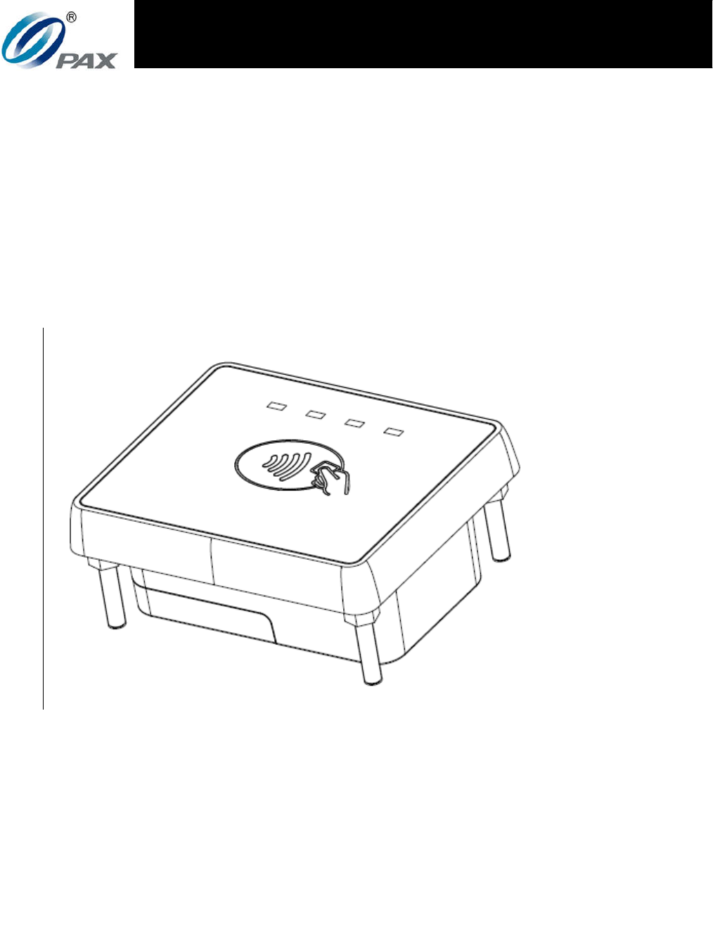
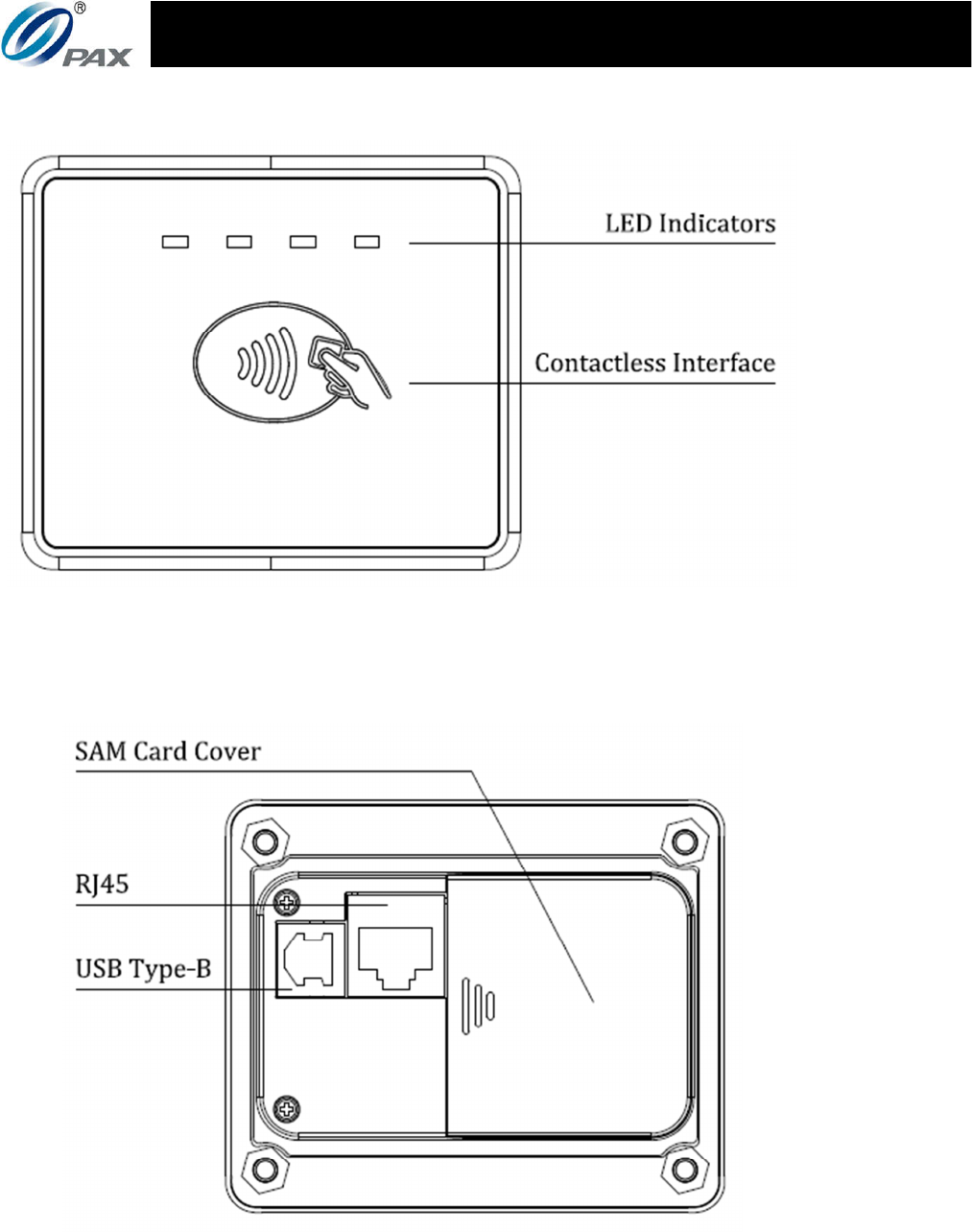
Figure 1: Front view
Figure 2: Back view
2
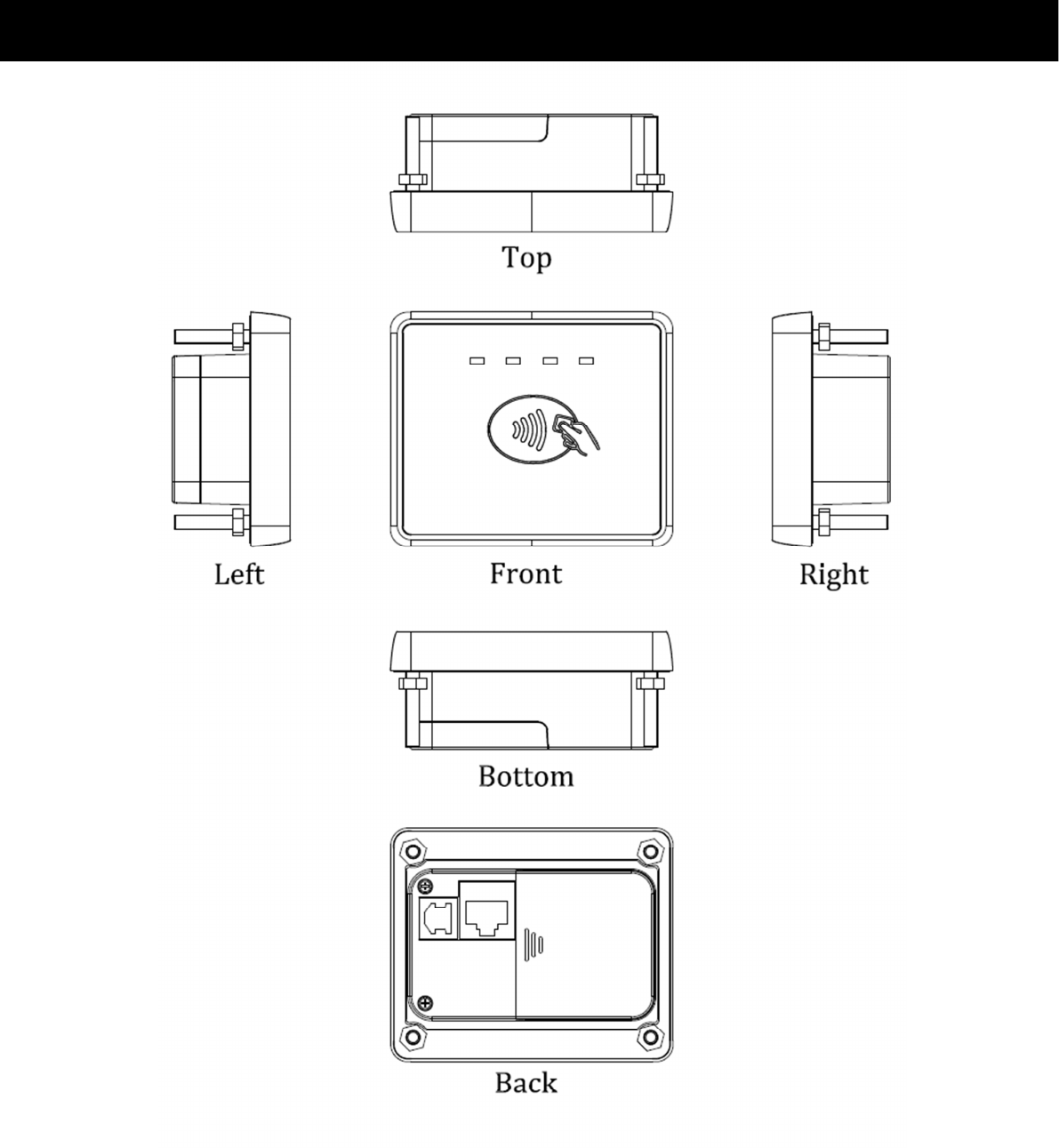
Figure 3: View from all angles
PAX TECHNOLOGY LIMITED
3
2
2.
.
I
In
ns
st
ta
al
ll
la
at
ti
io
on
n
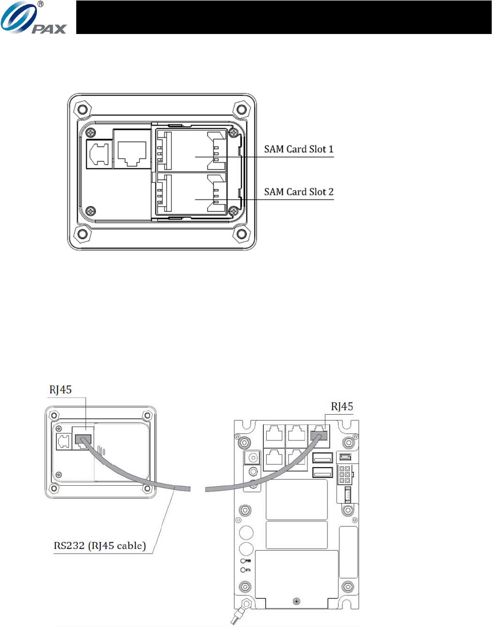
1) SAM Card
Figure 4: IM700 SAM card slots
Slide the SAM card cover to the side to remove it, then open
the mount and insert the card into the slot with the contact
facing down and the clipped edge oriented to the top right.
Afterwards, lock the mount with the card inside and replace
the cover.
2) Device Connection
Figure 6: Connecting the IM700 to an IM300 unit

4
The IM700 is connected to an IM300 encrypted PIN pad
through a RS232 serial port using a RJ45 cable as indicated in
Figure 6. The IM300 both controls and powers the IM700.
Note that the upper right RJ45 port on the IM300 is reserved
for the use of the IM700, do not connect the IM700 through
the other ports.
3
3.
.
I
In
ns
st
tr
ru
uc
ct
ti
io
on
ns
s
1) Switching the device on and off
Switch on: Connect the IM700 to an appropriate power
terminal either via USB or RJ45 (make sure to
have the appropriate voltages and pinouts).
Switch off: Disconnect the IM700 from whatever power
terminal(s) it is connected to.
2) Detecting contactless cards
Figure 7: IM700 interfacing with a contactless card
In order for the IM700 to detect and interface with contactless
cards, the user holds a contactless card with the face of the
card roughly 4 cm or less from the face of the device as shown
in Figure 5. The orientation of the card does not matter so
long as it is roughly facing the front of the device.

PAX TECHNOLOGY LIMITED
5
3) LED indicators
The different LED indicators show the following states for the
IM700:
○
1 All LEDs being in the off state means that the device is
unpowered or powering up and connecting to a terminal.
○
2 The blue LED indicates that the device is idle or ready for
transaction.
○
3 The yellow LED indicates that the device is processing
payments or other services.
○
4 The green LED indicates that the device has completed
processing the transaction.
○
5 The red LED indicates that the device has encountered an
error.
4
4.
.
S
Sp
pe
ec
ci
if
fi
ic
ca
at
ti
io
on
ns
s
CPU: 528MHz Application Processor
Operating System: Linux
Memory: 2Gb DDR3 SDRAM
1Gb NAND Flash
Contactless Reader: ISO/IEC 14443 Type A and Type B,
Mifare ®, and Felica
SAM Slots: 2 slots, ISO/IEC 7816
Peripheral Ports: 1 RS232 (RJ45)
1 USB 2.0 (USB Type-B)
Battery: 1 Nickel button battery, 200mAh, 3.0V
Power Supply: Input: 5VDC (USB2.0 Type-B)
12VDC (RS232 via RJ45)
Output: none
Buzzer: ≥75dB
Operating Environment: Temperature: -30°C~70°C
RH: 5%~95% (without condensation)

6
Storage Environment: Temperature: -30°C~70°C
RH: 5%~95% (without condensation)
Dimensions: 32.4mm x 82mm x 68mm (L x W x H)
5
5.
.
M
Ma
ai
in
nt
te
en
na
an
nc
ce
e
a
an
nd
d
U
Us
sa
ag
ge
e
1) Do not damage the USB or RJ45 cables; if either is damaged,
immediately discontinue their use and seek a replacement.
2) Make sure the terminals the USB or RJ45 cables connect to
provide the appropriate voltages at the proper pins.
3) Do not insert unknown materials into any port on the IM700,
this may cause serious damage to the device.
4) If the IM700 becomes defective, please contact a professional
technician for repairs instead of attempting them on your own.
5) The IM700 contains hardware tamper-proofing measures;
disassembly of the device will trigger the tamper circuits, at
which point it will have to be rearmed by qualified personnel
before the device is ready to resume operation.
6) The IM700 is designed for outdoor use; however, during
normal use its surface should still be keep clear of dirt and
possible liquid contaminants.
7) While the IM700 is designed to resist ingress of dust and
liquids from the front face, it is not designed to resist
pressurized liquids such as water hoses. Keep the back of the
device away from dust and liquids as much as possible.
6
6.
.
F
Fe
ed
de
er
ra
al
l
C
Co
om
mm
mu
un
ni
ic
ca
at
ti
io
on
n
C
Co
om
mm
mi
is
ss
si
io
on
n
I
In
nt
te
er
rf
fe
er
re
en
nc
ce
e
S
St
ta
at
te
em
me
en
nt
t
This device complies with Part 15 of the FCC Rules. Operation is
subject to the following two conditions: (1) This device may not
cause harmful interference, and (2) this device must accept any

PAX TECHNOLOGY LIMITED
5
interference received, including interference that may cause
undesired operation.
This equipment has been tested and found to comply with the
limits for a Class B digital device, pursuant to Part 15 of the FCC
Rules. These limits are designed to provide reasonable protection
against harmful interference in a residential installation. This
equipment generates, uses and can radiate radio frequency
energy and, if not installed and used in accordance with the
instructions, may cause harmful interference to radio
communications. However, there is no guarantee that
interference will not occur in a particular installation. If this
equipment does cause harmful interference to radio or television
reception, which can be determined by turning the equipment off
and on, the user is encouraged to try to correct the interference
by one of the following measures:
Reorient or relocate the receiving antenna.
Increase the separation between the equipment and receiver.
Connect the equipment into an outlet on a circuit different
from that
to which the receiver is connected.
Consult the dealer or an experienced radio/TV technician for
help.
F
FC
CC
C
C
Ca
au
ut
ti
io
on
n:
:
Any changes or modifications not expressly approved by the party
responsible for compliance could void the user's authority to
operate this equipment.

6
R
RF
F
E
Ex
xp
po
os
su
ur
re
e
I
In
nf
fo
or
rm
ma
at
ti
io
on
n
This device meets the government’s requirements for exposure to
radio waves.
This device is designed and manufactured not to exceed the
emission limits for exposure to radio frequency (RF) energy set by
the Federal Communications Commission of the U.S. Government.