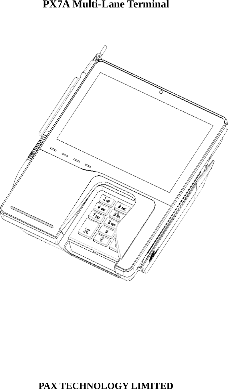
PAX Technology PX7ARF POS Terminal User Manual

PAX Technology Limited POS Terminal Users Manual

User Manual

PX7A Multi-Lane Terminal          PAX TECHNOLOGY LIMITED
1.Product Description   Top view  Bottom View
 SAM Slots View  PORTS View
2.Installation 1)  Recommend the designated fixture for PX7A and fix firmly.. 2) SAM Card and SD Card Installation:     Take off the Communications Module which is at the bottom of the terminal and insert the SAM Card or SD Card in the corresponding card slot respectively and set back the Communications Module.   3)  Connection to outer facility: Insert the Ethernet plug into the LAN socket of PX7A. Insert the serial facility into the socket of PX7A. Insert the USB apparatus into the USB port. Connection to AC power: Insert the DC outlet plug of standard power adapter into PX7A POWER socket. Insert the AC plug of power adapter into AC power socket. Please make sure the voltage of AC power within the recommended range.   4)  Turn on the AC  power switch, LCD backlight turns on, and the LCD screen enters the initialization interface. Then the application interface appears after initializing successfully. 5)  Simulating a transaction successfully means a good installation. 3.Instruction 1)  Magnetic swipe When pulling a magnetic card along the slot, make the magnetic stripe face the operator as indicated on the PX7A card. Bi-directional pulling the magnetic card is acceptable. It is recommended from top to bottom or vice versa, with constant speed. 2)  IC card operation description When inserting a card, push the IC card to the end of the slot, as indicated on the Px7 IC card (with the chip upside). Gently insert and withdraw the card In order to protect the contact on card and IC card connector. ICC Operation Process Before inserting the IC card, please check inside and around the IC card slot. If there is any suspicious object, please don‘t insert card and immediately report to the relevant staff. 3)  Signature input When signature required on the screen, either using input pen or using fingers, (no gloves and long finger nails), signed in the designated region. 4.Specification Default CPU:    ARM Cortex-A53, Quad-core,1.2GHz Memory:    8GB EMMC 1GB DDR3 ram Display:        7.0-inch 1024X600 pixel color TFT LCD. Touch Screen:     Capacitive Touch Panel with stylus Camera    Front 5 million pixel camera Keypad:        ADA style keypad, with 10 alphanumeric keys, and 3 functional keys Audio:        Built-in double speakers supporting stereo.      A 3.5mm audio port. Magnetic Card Reader:  Track 1/2/3, bi‐directional swipe IC Card Reader:    1 user card (EMV2000). SAM Card:      2 sockets, ISO7816. Peripheral Ports:      1 RS232; 2 LAN; 1 PUSB (DEVICE); 1 USB (HOST); 1 Power Socket; 1 SD Card slot.
Power Adapter:      Input: 100~240VAC,50Hz/60Hz, 0.6 A Output: 9 VDC, 1 A Working Environment:   Temperrature:0℃~50℃(32℉~122℉) R.H.: 10%~93% (non-condense) Storage Environment:    Temperrature: -20℃~60℃(-4℉~158℉) R.H.5%~90% (non‐condense) Dimensions:      200mm×185mm×44mm (L×W×H) Weight:        741g optional:  Contactless card reader   5.Notice at Installation and Use 1) Adopt a power socket with fuse and well-grounded. 2) No use of broken power cord or power adapter. Once injury of power cord or power adapter is found, stop using it in case of electrocution. 3) Before connecting the power to the AC socket, please make sure the voltage comply with the POS Spec. 4) It is better to place the device on the designated fixture and fix firmly. It is not allowed to use it in the environment of direct sun beam, high temperature, heavy humidity or much dust. 5) Keep away from liquid. 6) Don’t insert any other stuff into any port of device, which may damage the device seriously. 7) When POS is in failure, please contact with maintenance technicians of POS. It’s not allowed to repair on your own. 8)  Keep away from bomb and hazardous area. 9) Keep far away electromagnetic device and environment of excessive radiation. 10)  When connect to Ethernet, only indoor internet can be used in case of thunder strike. 11)  It’s better to use privacy shield when PIN-entry, refer to the techniques of item 6 to prevent PIN pilferage. 6.PIN Protection The following techniques can be employed to provide for effective screening of the PIN-entry during the PIN entry process. These methods would typically be used in combination, though in some cases a method might be used singly. Positioning of terminal on the check-stand in such way as to make visual observation of the PIN-entry process infeasible. Examples include: − Visual shields designed into the check-stand. The shields may be solely for shielding purposes, or may be part of the general check-stand design, e.g., used as selling area.   − Position the PED so that it is angled in such a way to make PIN spying difficult. Installing PED on an adjustable stand that allows consumers to swivel the terminal sideways and/or tilt it forwards/backwards to a position that makes visual observation of the PIN-entry process difficult. Positioning of in-store security cameras such that the PIN-entry keypad is not visible. Post instructions around check-stand, in order to inform customers. Instructing the cardholder regarding safe PIN-entry. When the cardholder input his/her PIN, he/she had better use his/her body and hands to prevent visual observation of PIN-entry process.  Note:To protect the process of PIN-entry, it is not limited to the above methods and examples, merchants also can adopt other methods and steps to keep cardholder’s PIN safe.
Table:PX7A PIN-entry observation corridors v.s. PIN protection methods  Observation Corridors Method Cashier Customers in Queue Customers Elsewhere On-Site Camera Remote Cameras PX7A in Check-Stand with shield H  H  M  H  H PX7A on Adjustable Stand H  H  H  M  M Post Customer Instruction H* H* H* H* H* Note *Customer instruction methods are less repeatable and therefore should be used in combination with other methods. Security levels: L = low,M = medium,H = high  This device complies with Part 15 of the FCC Rules. Operation is subject to the following two conditions: (1) This device may not cause harmful interference, and (2) this device must accept any interference received, including interference that may cause undesired operation.  This equipment has been tested and found to comply with the limits for a Class B digital device, pursuant to Part 15 of the FCC Rules.  These limits are designed to provide reasonable protection against harmful interference in a residential installation. This equipment generates, uses and can radiate radio frequency energy and, if not installed and used in accordance with the instructions, may cause harmful interference to radio communications.    However, there is no guarantee that interference will not occur in a particular installation.    If this equipment does cause harmful interference to radio or television reception, which can be determined by turning the equipment off and on, the user is encouraged to try to correct the interference by one of the following measures:   Reorient or relocate the receiving antenna.  Increase the separation between the equipment and receiver.  Connect the equipment into an outlet on a circuit different from that to which the receiver is connected.  Consult the dealer or an experienced radio/TV technician for help.  FCC Caution:  Any changes or modifications not expressly approved by the party responsible for compliance could void the user's authority to operate this equipment.  This transmitter must not be co-located or operating in conjunction with any other antenna or tran s mi tte r.    This device complies with Industry Canada license-exempt RSS standard(s). Operation is subject to the following two conditions:   1) this device may not cause interference, and   2) this device must accept any interference, including interference that may cause undesired operation of the device.  Le présent appareil est conforme aux CNR d'Industrie Canada applicables aux appareils radio exempts de
licence. L'exploitation est autorisée aux deux conditions suivantes:   1) l'appareil ne doit pas produire de brouillage, et   2) l'utilisateur de l'appareil doit accepter tout brouillage radioélectrique subi, même si le brouillage est susceptible d'en compromettre le fonctionnement.   This device and its antenna(s) must not be co-located or operating in conjunction with any other antenna or transmitter, except tested built-in radios.    Cet appareil et son antenne ne doivent pas être situés ou fonctionner en conjonction avec une autre antenne ou un autre émetteur, exception faites des radios intégrées qui ont été testées.     The County Code Selection feature is disabled for products marketed in the US/ Canada.  La fonction de sélection de l'indicatif du pays est désactivée pour les produits commercialisés aux États-Unis et au Canada.

Navigation menu