PAYNE Furnace/Heater, Gas Manual L0523315
User Manual: PAYNE PAYNE Furnace/Heater, Gas Manual PAYNE Furnace/Heater, Gas Owner's Manual, PAYNE Furnace/Heater, Gas installation guides
Open the PDF directly: View PDF ![]() .
.
Page Count: 49
PG8M/PG8J
Installation, Start-up, Operating, and
Service and Maintenance Instructions
-Series C
4@<
@©_@ 0@ <
4©<
@
The Payne PG8M/PG8J 80% AFUE Gas Furnaces feature 4-
way multipoise design and through-the-furnace downflow
venting. The PG8M/PG8J furnaces are approved for use with
natural or propane gas and the PG8J is also approved for use in
Low Nox Air Quality Management Districts.
STANDARD FEATURES
•Four-position furnace: upflow, horizontal right, horizontal
left, downflow
•Electronic control center
Adjustable heating air temperature rise
LED diagnostics and self test feature
•Hot surface ignition (HSI)
•Twinning in Upflow, Downflow and Horizontal
LIMITED WARRANTY
• 20-year warranty on "Super STM''heat exchanger
• 5-year parts warranty on all other components
Catalog No: 53PG-8J5 Form No. IM-PG8J-05 5-05
Induced-Combustion
{nstallation,
Service and
Cancers: II 310A-45°4/IM-PG8J-04
A li310_k-45-5/IM-PG8Jo0_5
Start-up, upera mng, ane
Maintenance Instructions
Series 120/0
NOTE: Read the entire instruction manual before starting the
installation.
This symbol --> indicates a change since the last issue,
--> PoItions of the text and tables are repiinted fiom NFPA 54/ANSI Z223 1-2002"<',
with permisslol_ of National Fire Protection Association, Quincy, MA 02269 and
Ameiican Gas Association. Washingto_ DC 20001 This reprinted material is l_ot/he
complete and official position of the NFPA or ANSI on the ref?renced suNect, which
is repiesented only by the standmd in its entirety
TABLE OF CONTENTS
SAFETY CONSIDERATIONS 2
INTRODUCTION ..................................... 4
CODES AND STANDARDS ........................................................ 4
Safety ......................................................................................... 5
General Installation ................................................................... 5
(onfhustion and Ventilation Air .............................................. 5
Duct Systems ............................................................................ 5
Acoustical Lining and Fibrous Glass Duct .............................. 5
Gas Piping and Gas Pipe Pressure Testing .............................. 5
Electrical Connections .............................................................. 5
ELECTROSTATI( DISCHARGE (ESD) PRECAUTIONS
PRO(EDURE ................................................................................ 5
LOCATION .................................................................................... 5
General ...................................................................................... 5
Location Relative to Cooling Equipment ................................ 7
AIR FOR COMBUSTION AND VENTILATION ...................... 7
INSTALLATION ......................................................................... 10
Lpftow Installation ................................................................. i0
Bottom Return Air Inlet .................................................... i0
Side Return Air Inlet ......................................................... 10
Leveling Legs (If Desired) ................................................ 10
Downftow Installation ............................ 10
Bottom Return Air Inlet ......................... 11
Horizontal Installation ............................. 11
Suspended Furnace Support ...................... 11
Platfbrm Furnace Support ........................ i 1
Roll-Out Protection .............................. 11
Bottom Return Air Inlet ......................... 1l
Side Return Air Inlet ........................... 11
Filter Arrangement ................................ 11
Air Ducts ........................................ 11
General Requirements ............................ 11
Ductwork Acoustical Treatment .................... 12
Supply Ai* (onnections ......................... 12
Return Air Connections .......................... 14
Gas Piping ...................................... 15
Electrical ( onnections ............................ 19
115=V Wiring ................................ 19
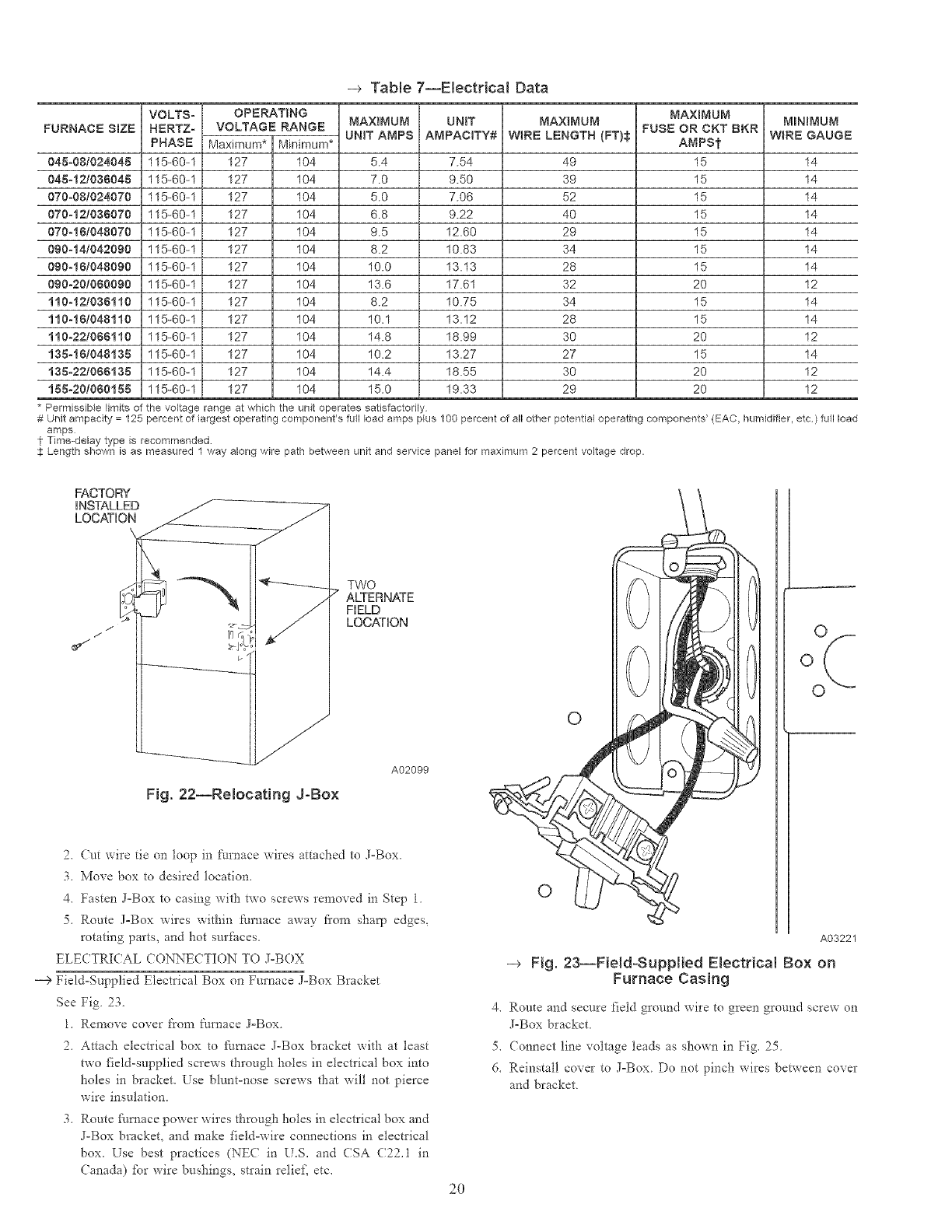
J°Box Relocation .............................. 20
Electrical Connection to J°Box ..................... 21
Power Cord Installation in Furnace J=Box ............. 21
BX Cable Installation in Furnace J°Box .............. 22
RSO 9001:2000
24-V Wiring ....................................................................... 22
Accessories ........................................................................ 22
Venting .................................................................................... 22
General Venting Requirements ......................................... 23
Masonry (himney Requirements ...................................... 23
Appliance Application Requirements ............................... 24
Additional Venting Requirements ..................................... 26
Sidewall Venting ............................................................... 26
START°UP, ADJE STMENT, AND SAFETY CHECK ............ 27
General .................................................................................... 27
Start-Up Procedures ................................................................ 27
Adjustments ............................................................................. 3l
Check Safe w Controls ............................. 34
Checklist .......................................... 35
SERVICE AND MAINTEiN'ANCE PROCEDURES ........... 35
Intro&ction ....................................... 35
General ........................................ 35
Electrical Controls and Wiring ..................... 36
(are and Maintenance .............................. 37
Cleaning and/or Replacing Air Fiher ................. 37
Blower Motor and Wheel ......................... 37
Cleaning Heat Exchanger ........................ 40
Sequence of Operation ............................. 44
Wiring Diagrams .................................. 45
Troubleshooting .................................. 45
Manufacturer reserves the right to discontinue, or change at any time, specifications or designs without notice and without incurring obligations.
B°°k 1h_ PC 101 catalog No See Cover Printed in USA Form 58ST-13SI Pg 1 5-05 Replaces: 58S%12SI
Tab 16al 8a
28 7/8" --
26 I/8"
(FLI JE COLLAR)
5 15,q6" --
78" DIA I I
ACCESSORY 7
33 5¸'¸¸[6,`
/I /6"_
-- 25 I/4" --
_- 22 _/6" --
3 15/6" S
LEFT HAND GASJ
ENTRY
78" D]A ACCESSORY-
21 5/8"
BOTTOM INLET
24"
CASING
24 7,8"
_i /,2"
_A--
-- D --
lOCATIONS (TYP}
5 PLACES (TYP}
T
t
--/116"
S]DEINLET
'I
9 5_8"
A04037
NOTES:
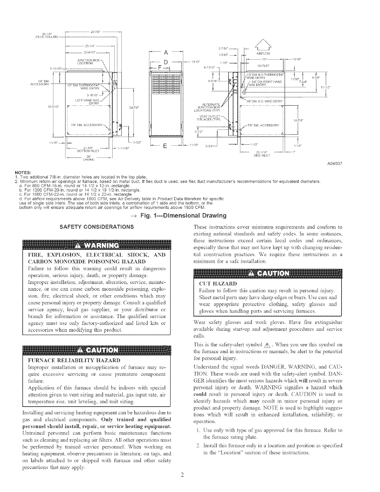
1. Two additional 7/8-in diameter holes are located in the top plate.
2. Minimum return-air openings ar furnace, based on metal duct. If flex duct is used, see flex duct manufacturer's recommendations for equivalent diameters
a For 800 CFM-16qn round or 14 1/2 x 12qn. rectangle
b For 1200 CFM-20-in. round or 14 1/2 x 19 1/2qn rectangle.
c. For 1600 CFM-22qn. round or 14 1/2 x 22-in rectangle.
d For airflow requirements above 1800 CFM, see Air Delivery table in Product Data literature for spedfic
use of single side inlets. The use of both side inlets, a combination of 1 side and the bottom, or the
bottom only will ensure adequate return air openings for airflow requirements above 1800 CFM
-_ Fig. 1--Dimensional Drawing
SAFETY CONSIDERATIONS
FIRE, EXPLOSION, ELECTRICAL SHOCK, AND
CARBON MONOXIDE POISONING HAZARD
Failure to follow d-fis warning could result in dangerous
operatiom serious injury, death, or property damage
Improper installation, adjustment, alteration, service, mainte-
nance, or use can cause carbon monoxide poisoning, explo-
sion, fire, electrical shock, or other conditions which may
cause personal inju Wor property damage. Consuh a qualified
service agency, local gas supplier, or your distributor or
branch fbr infPm_ation or assistance. The qualified service
agency must use only fSctory=authorized and listed kits or
accessories when modif}qng this product.
FURNACE RELIABILITY HAZARD
Improper installation or misapplication of furnace may re=
quire excessive servicing or cause premature component
failure
Application of"this fftrnace should be indoors with special
attention given to vent sizing and material, gas input rate, air
temperature rise, unit leveling, and unit sizing
Installing and servicing heating equipment can be hazardous due to
gas and electrical components. Only trained and qualified
personnel should instMl, repair, or service heating eqnipment.
Untrained personnel can perform basic maintenance functions
such as cleaning and replacing air filters. All other operations must
be performed by trained service personnel. When working on
heating equipment, observe precautions in literature, on tags, and
or* labels attached to or shipped with £urnace and other safety
precautions that may apply.
These instructions cover minimum requirements and con%,Tn to
existing national standards and safety codes In some instances_
these instructions exceed certain local codes and ordinances,
especially those that may not have kept up with changing residen=
tial construction practices We require these instructions as a
minimum for a saf_ installation
(:liT HAZARD
Failure to fbllow d_is caution may result in personal ir_jury.
Sheet metal parts may have sharp edges or butts Use care and
wear appropriate protective clothing, safety glasses and
gloves when handling parts and servicing fhrnaces.
Wear safety glasses and work gloves. Have fire extinguisher
available daring start-up and ad.iustment procedures and service
calls.
This is the safety=alert syn£bol Z_ • When you see this syn_bol on
the fhmace and in instructions or manuals, be alert to the potential
for personal injury.
Understand the signal words DANGER, WARNING, and (AU=
TION. These words are used with the safkty=alert symbol. DAN-
GER identifies the most serious hazards which will result in severe
personal injury or death. WARNING signifies a hazard which
conld result in personal injury or death. CAUTION is used to
identify hazards which may result in minor personal ir_jury or
product and property damage. NOTE is used to highlight sugges=
tions which will result in enhanced installation, reliabili w, or
operation.
1. Use only with type of gas approved tbr this filrnace. Refkr to
the [_urnace rating plate.
2. Install this Nrnace only in a location and position as specified
in the "Location" section of these instructions.
MINIMUMINCHESCLEARANCETO COMBUSTIBLECONSTRUCTION
DISTANCEMINIMALE ENPOUCESAUX CONSTRUCTIONSCOMBUSTIBLES
Thisforced air furnace is equippedfor use wi_ PqisfiJmaceisapprovedforUPFLOW,DOWNFLOW,and
naturalgas at altitudes0-10,000ft (0-3,050m). HORIZONTALinstallations.
An accessory kit, supplied by De Cettefournaiseestapprouveepourl'installationHORIZONTALE
manuf_turer, shall be used to convert to propane etlac£culationd 'airVERSLEHAUTet VERSLEB._S.
gas use or may be requiredfor some natural gas /_,,_->
applications. Clearancearrows /',,_ Lesfbchesded@gagement
This furnace is for indoor installation in a donotchangew}th L _ nechangepasavec
furnace orientatior_ z u._ I 'orientation de la feamaise,
buildingconstructedon site. ._
Thisfumase maybe installedon combustible _
oonng
as indicated by the diagram from combusiible _.
msterial.
Thisfurnacemay be used with a Type B-1 Vent
and may be vented in common wi_ other gas ",_ _ ,so_._._.
Cet[e fournaisea air pulseest equipee _ r_._,- i s=_
pour utilisaiJon avec gaz nafurel et altitudes
comprisesentre G3,050m (0-I0,000 pi). e\O_
Utiliserune trousse de conversion,foumie par co_
lefabrinant,pourpasserau gaz propane ou pour _.
certainesinstallationsau gaz naturel. "_ oz_i b"
Cettefoumaiseest pr@ue pour @e
installeedans un b_lJmentconstruitsur place. _ _ _./ Clearanceininches
Cettefournaise peut 6tre install@esur <_// D_agernent(po}.
un planc'hercambusiJbledansune alc6veou
dans un garde-robeen respectantle minimum <:_'/
d'espace libredes materiauxcombustibles,tel Vent Clearanceto combustibles:
qu'indique sur le diagramme. For Single WalJ versts 6 inches (6 po).
Cette fournaise peut @-e utilisee avec un For Type B-1 vent type 1 inch (1 po).
Degagementde I'@entavec combustibles:
conduitd'@acuationde Type B-1 ou connectee Pearconduitd'evacuationa paroi simpb 6 po(6 inches).
au conduit ommun d 'autres appareilsa gaz. Pearcor_duitd'@aeaationdeTypeB-11Fo(1inch).
MINIMUM INCHES CLEARANCE TO COMBUSTIBLE CONSTRUCTION
I)OWNFLOWPOSITIONS:
1" InstallaiJonon non-combusibiblefloorsonly.
For Installationon combustibleflooring only when installedon special base,Part No. KGASB020IALL,
Coil Assembly,PartNo. CD5 or CK5, or CoilCasing,Part [/o. KCAKC.
O 18 inchesfront clearancerequiredfor alcove.
_r Indicatessupplyor returnsideswhen furnace isin [he horizontalposition.Linecontactonly permissible
betweenlinesformed by intersectionsof the Top and bJvoSides of the furnacejacket,and buildingjoists,
studsor framing.
DC:GAGEMENTMINimUMEN POUCESAVEC €:LE_ENTS
DE CONSTRUCTION COMBUSTIBLES
POURLAPOSITIONCOURANTDESCENDANT:
1" Pour rinstallationsur planchernon combus_bleseulement.
Pour rinstallationsur un planchercombusiJbleseulementquandon utilisela basespedale, piece
n° KGASB020IALL rensembleserpen_Jn,piecen° CD5 ou CK5, ou le narterde serben_Jn,piece
n° KCAKC.
Dans une alc6ve,on dolt maintenirun decjagementa ravant de 18po (450mm).
"/_ La poistion indiqueeconceme lec6ted'en_-eeou de retourquand lafournaiseestdans la
positionhorizontale.
Le contact n'est permis qu'entreles lignesformees par les intersectionsdu dessus et des
deuxc6tes de lacherfise de la fournaiseet lessolives,montantsous cadre de charpenta.
k. 327590-101 REV. C
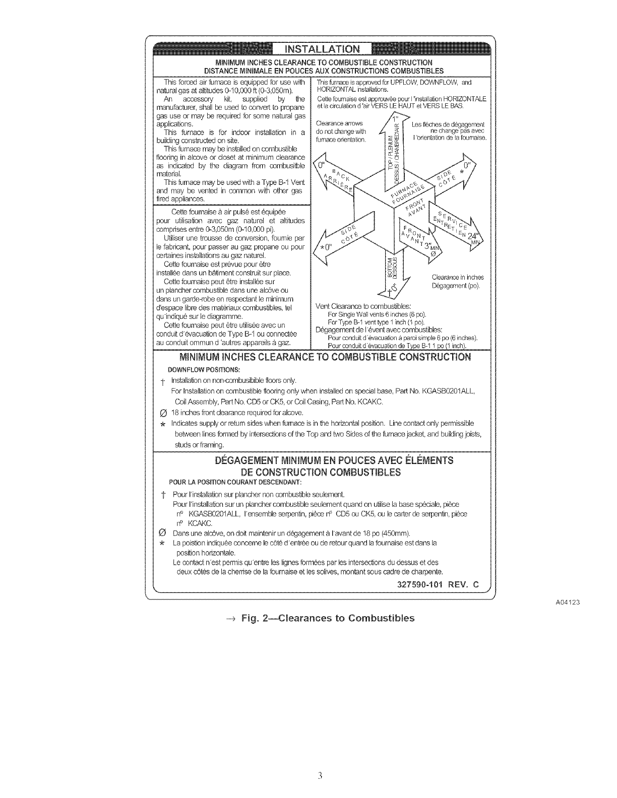
--> Fig. 2--Clearances to Combustibles
A04123
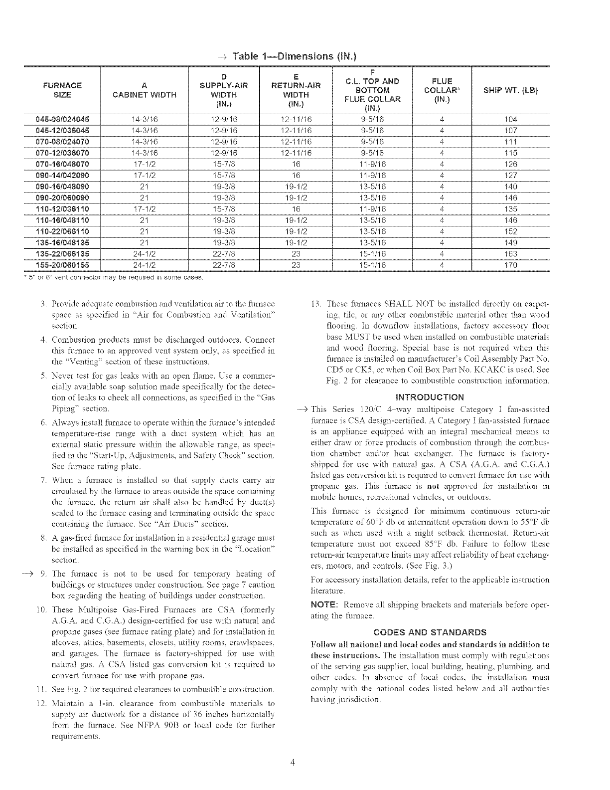
-_ Table 1--Dimensions (iN.)
F
D E C.L TOP AND FLUE
FURNACE A SUPPLY-AIR RETURN-AiR BOTTOM COLLAR* SHIP W% (LB}
$tZE CABINET W_DTH WIDTH WIDTH FLUE COLLAR {BN.}
(tN.) (IN.) (RN.}
045=08t024045 14-3/16 12=9/16 12-11/16 9=5/16 4 104
045=12t036045 14-%16 12-9/16 12-11/16 9=5/16 4 107
070=08t024070 14-3/16 12=9/16 12-11/16 9=5/16 4 111
070=12t036070 14-%16 12-9/16 12-11/16 9-5/16 4 115
070-161048070 17-1/2 15-7/8 16 11-9/16 4 126
090_14/042090 17-1/2 15-7/8 16 11-9/16 4 127
090-18/048090 21 19-3/8 19=1/2 13-5/16 4 140
090-20t060090 21 19-3/8 19-1/2 13-5/16 4 146
t10-12/036110 17-1/2 15-7/8 16 11-9/16 4 135
110_181048110 21 19-3/8 19-1/2 13-5/16 4 146
t10=22/066110 21 19-3/8 19=1/2 13-5/16 4 152
135-16/048185 21 19-3/8 19-1/2 13-5/16 4 149
t35-22/066188 24-1/2 22-7/8 23 15-1/16 4 163
188-20t080155 24-1/2 22-7/8 23 15-1/16 4 170
* 5" or 6 _vent connector may be required in some cases.
--> 9,
3. Provide adequate combustion and ventilation air to the furnace
space as specified in "Air _br Combustion and Ventilation _'
section.
4. (ombustion products must be discharged outdoors. Connect
this _i/mace to an approved vent system only, as specified in
the "Venting" section of these instructions.
5. Never test for gas leaks with an open flame. Use a commer-
cially available soap solution made specifically for the detec-
tion of leaks to check all connections, as specified in the "Gas
Piping" section.
d. Always install Nmace to operate within the fmnace's intended
temperature-rise range with a duct system which has an
external static pressure within the allowable range, as speci-
fied in the "Start-Up, Adjustments, and Safety Check" section.
See Nmace rating plate.
7. When a fitrnace is installed so that supply ducts cat_T air
circulated by the t_urnace to areas outside the space containing
the furnace, the remm air shall also be handled by duct(s)
sealed to the _i/raace casing and terminating outside the space
containing the Nrnace. See "Air Ducts" section.
8. A gas-fired _lrnace fbr installation in a residential garage must
be installed as specified in the warning box in the "Location _'
section.
The furnace is not to be used [br temporary heating of
buildings or stl_ctures under construction. See page 7 caution
box regarding the heating of buildings under construction.
10. These Multipoise Gas-Fired Furnaces are (SA (fbrmerly
A.G.A. and (LG.A0 design-certified for use with natural and
propane gases (see furnace rating plate) and for installation in
alcoves, attics, basements, closets, utility rooms, crawlspaces,
and garages. The furnace is factory°shipped _br use with
natural gas. A CSA listed gas conversion kit is required to
convert furnace [or use with propane gas.
11. See Fig. 2for required clearances to combustible construction.
12, Maintain a l-in. clearance from combustible materials to
supply air ductwork J:br a distance of 36 inches horizontally
_?om the Nmace. See NFPA 90B or local code for Nrther
requirements,
--€
13, These _amaces SHALL NOT be installed directly on carpet-
ing, tile, or any other combustible material other than wood
flooring. In downflow installations, _i_ctow- accessow- floor
base MUST be used when installed on combustible materials
and wood flooring. Special base is not required when this
_i/mace is installed on manu_hcturer's (;oil Assernhly Part No.
(D5 or CK5, or when (Toil Box Part No. KCAKC is used. See
Fig. 2 for clearance to combustible constluction information.
INTRODUCTION
This Stoics 120/( 4 way multipoise Category I _m-assisted
furnace is (SA design=certified. A Category I fan-assisted furnace
is an appliance equipped with an integral mechanical means to
either &aw or force products of combustion through _he combus=
tion chamber and/or heat exchanger. The _urnace is factor'-
shipped fbr use with natural gas. A CSA (A.G.A. and C.G.A.)
listed gas conversion kit is required to convert [:urnace for use with
propane gas. This Nmace is no{ approved fbr installation in
mobile homes, recreational vehicles, or outdoors.
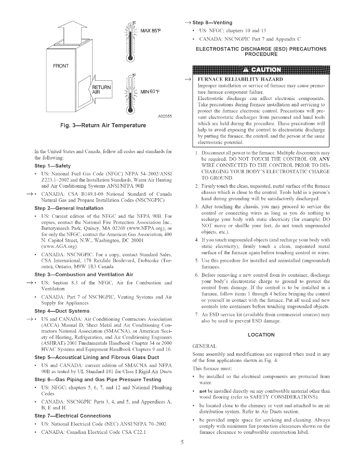
This Nrnace is designed for minimuna continuous return-air
temperature of 60_>F db or intermittent operation down to 55°F db
such as when used with a night setback thermostat. Return-air
temperature must not exceed 85°F db. Failure to follow these
return-air temperature limits may afi:kct reliability of heat exchang-
ers, motors, and controls. (See Fig. 3.)
For accessoQ" installation details, re['cr to the applicable instruction
literature.
NOTE: Remove all shipping brackets and materials before oper-
ating the furnace.
CODES AND STANDARDS
Follow all national and local codes and standards in addition to
these ins{factions. The installation must comply with regulations
of the serving gas supplier, local building, heating, plurnhing, and
other codes. In absence of local codes, the installation must
comply with the national codes listed below and all authorities
having jurisdiction.
FRONT
MAX 85°F
MIN 60°F
Fig. 3--Return Air Temperature
A02055
In the [ nited States and Canada, follow all codes and standards for
the ibllowing:
Step l--Safety
• US: National Fuel Gas Code (NFGC) NFPA 54 2002/ANSI
Z223.1 2002 and the Installation Standards, Wam_ Air Heating
and Air Conditioning Systems ANSI NFPA 90B
--> ° CANADA: CSA B149.1-00 National Standard of Canada
Natural Gas and Propane Installation Codes (NSCNGPI()
Step 2--General hstallation
• US: Current edition of the NFGC and the NFPA 90B. For
copies, contact the National Fire Protection Association Inc.,
BattelTmarch Park, Quincy, MA 02269 (www.NFPA.org); or
for only the NFGC, contact the American Gas Association, 400
N. Capitol Street, N.W., Washington, DC 20001
(www.AGA.org).
• CANADA: NSCNGPIC. For a copy, contact Standard Sales,
CSA International, 178 Rexdale Boulevard, Etobicoke (Tor-
onto), Ontario, M9W 1R3 Canada
Step 3--Combustion and Ventilation Air
--> • US: Section 8.3 of the NFGC, Air for (ombustion and
Ventilation
• CANADA: Part 7 of NSCNGPIC, Venting Systems and Air
Supply fbr Appliances
Step 4--Duct Systems
--> * US and CANADA: Air (onditioning Contractors Association
(ACCA) Manual D_ Sheet Metal and Air Conditioning Con-
tractors National Association (SMACNA), or American Soci-
ety of Heating, Refrigeration, and Air Conditioning Engineers
(ASHRAE) 2001 Fundamentals Handbook Chapter 34 or 2000
HVAC Systems and Equipment Handbook Chapters 9 and 16.
Step 5--Acoustical Lining and Fibrous Gtass Duct
• US and CANADA: current edition of SMA(NA and NFPA
90B as tested by UL Standard 181 fbr Class I Rigid Air Ducts
Step 6--Gas Piping and Gas Pipe Pressure Testing
• US: NFGC; chapters 5, 6, 7, and 12 and National Phnnbing
Codes
• CANADA: NSCNGPIC Parts 3, 4, and 5, and Appendices A,
B, E and H
Step 7--Electrical Connections
• US: National Electrical Code (NEC) ANSI NFPA 70 2002
• CANADA: Canadian Electrical Code CSA C22 1
--> Step 8--Venting
*US: NFGC: chapters 10 and 13
* (ANADA: NSCNGPI( Part 7 and Appendix C
ELECTROSTATIC DBSCHARGE {ESD) PRECAUTIONS
PROCEDURE
--> FURNACE RELIABILITY HAZARD
Improper installation or service of furnace may cause prema-
ture thrnace component failure
Electrostatic discharge can affect electronic components.
Take precautions during thrnace installation and servicing to
protect d_e thmace electronic control. Precautions will pre-
vent electrostatic discharges ti'om personnel and hand tools
which are held during the procedure. These precautions will
help to avoid exposing the control to electrostatic discharge
by putting the thmace, the control, and the person at the same
electrostatic potential.
1. Disconnect all power to the furnace. Multiple disconnects may
be required. DO NOT TOUCH THE CONTROL OR ANY
WIRE C ONNE(TED TO THE CONTROL PRIOR TO DIS-
CHARGING YOUR BODY'S ELECTROSTATI( CHARGE
TO GROUND,
2 Firmly touch the clean, unpainted, metal surface of the fi.maace
chassis which is close to the control. Tools held in a person's
hand dtlring grounding will be satisfactorily discharged.
3. After touching the chassis, you may proceed to service the
control or connecting wires as tong as you do nothing to
recharge your body with static electricity (for example; DO
NOT move or shuffle your feet, do not touch ungrounded
objects, etc.).
4. If you touch ungrounded ohjects (and recharge your body with
static electricity), firmly touch a clean, unpainted metal
surface of the fiul_ace again be:R_re touching control or wires.
5. Use this procedure for installed and uninstalled (ungrounded)
_i/rnaces
6. Before removing a new contact fi'om its container, discharge
your bo@'s electrostatic charge to ground to protect the
control _i'om damage. If d_e control is to be installed in a
_i/mace, _bltow items 1 through 4 befbre bringing the control
or yourself in contact with the furnace. Put all used and new
controls into containers befbre touching ungrounded objects.
7. An ESD service kit (available from commercial sources) may
also be used to prevent ESD dan?age.
LOCATION
GENERAL
Some assembly and modifications are required when used inany
of the four applications shown in Fig_ 4,
This thmace must:
* be installed so the electrical components are protected from
water
* not be installed directly on any combustible material other than
wood flooring (refer to SAFETY CONSIDERATIONS)
* be located close to d-_echinmey or vent and attached to an air
distribution system, Refer to Air Ducts section,
* be provided ample space fbr servicing and cleaning. Always
comply with mininmm fire protection clearances shown on the
fro'hate clearance to combustible consm/ction 1abel
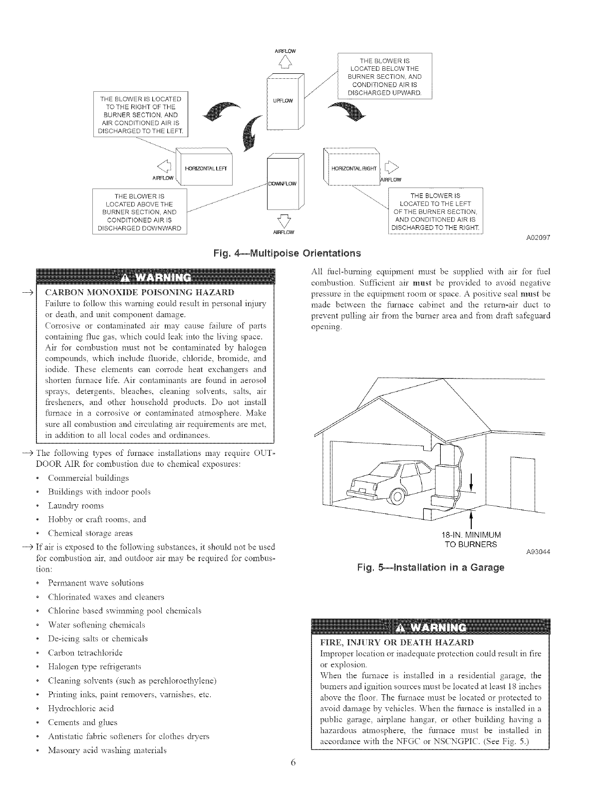
THE BLOWER IS LOCATED
TO THE RIGHT OF THE
BURNER SECTION, AND
AIR CONDITIONED AIR IS
DISCHARGED TO THE LEFT
HORIZONTAL LEF[
AIRFLOW
THE BLOWER IS
LOCATED BELOW THE
BURNER SECTION. AND
CONDITIONED AIR IS
DISCHARGED UPWARD.
--€
THE BLOWER IS
LOCATED ABOVE THE
BURNER SECTION, AND
CONDITIONED AIR IS
DISCHARGED DOWNWARD
Fig. 4_Multipoise Orientations
CARBON MONOXIDE POISONING HAZARD
Failure to fbllow this warning could result in personal injuU
or death, and unit component damage.
(mTosive or contaminated air may cause failure of parts
containing flue gas, which could leak into the living space.
Air for confbustion must not be contaminated by halogen
compounds, which include fluoride, chloride, bromid< and
iodide. These elements can con'ode heat exchangers and
shorten fhrnace life. Air contaminants are found in aerosol
sprays, detergents, bleaches, cleaning solvents, salts, air
fresheners, and other household products. Do not install
furnace in a corrosive or contaminated atmosphere. Make
sure all confbustion and circulating air requirements are met,
in addition to all local codes and ordinances.
A02097
All f_el-burning equipment n-rest be supplied with air %r fuel
combustion Sufficient air must be provided to avoid negative
pressure in the equipment room or space A positive seal must be
made between the filrnace cabinet and the return=air duct to
prevent pulling air fi'om the burner area and from draft safeguard
opening.
--> The %llowing types of t\_rnace installations may require OLT=
DOOR AIR _br combustion due to chemical exposures:
Commercial buildings
Buildings with indoor pools
Laundv rooms
Hobby or craft rooms, and
Chemical storage areas
--> If air is exposed to the/bllowing substances, it should not be used
tbr combustion air, and outdoor air may be required tbr combus=
tion:
Permanent wave solutions
Chlorinated waxes and cleaners
Chlorine based swimming pool chemicals
Water softening chemicals
Deqcing salts or chemicals
Carbon tetrachloride
Halogen type refrigerants
Cleaning solvents (such as perchloroethylene)
Printing inks, paint removers, varnishes, etc,
Hydrochloric acid
Cements and glues
Antistatic ti_bric softeners tbr clothes dwers
Mason U- acid washing materials
18-1N. MINIMUM
TO BURNERS
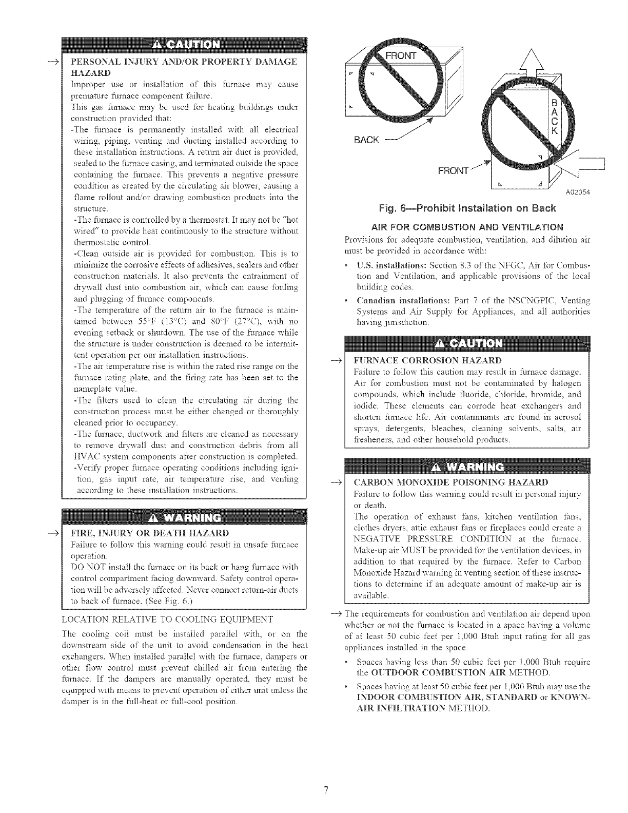
Fig. 8--Installation in a Garage
A93044
FIRE, INJURY OR DEATH HAZARD
Improper location or inadequate protection could result in fire
or explosion
When the furnace is installed in a residential garage, the
burners and ignition sources must be located at least 18 inches
above the floor The fi/rnace must be located or protected to
avoid damage by vehicles. When the furnace is installed in a
public garage, airplane hangar, or other building having a
hazardous atmosphere, the _\trnace must be installed in
accordance with the NFGC or NS(NGPI(. (See Fig 5)
--9
HAZARD
Improper use or installation of this furnace may cause
premature_mmce componentf_tilure,
This gas fl/ruace may be used for heating buildings under
construction provided that:
-The furnace is permanently installed with all electrical
wiring, piping, venting and ducting installed according to
these installation instructions A return air duct is provided,
sealed to the f_mlace casing, and tem_inated outside the space
containing the f_/mace. This prevents a negative p*essure
condition as created by the circulating air blower, causing a
flame rollout and/or drawing combustion products into the
structure.
-The fhmaee is controlled by a thermostat It may not be "hot
wired" to provide heat continuously to the structure without
them_ostatic control
-Clean outside air is provided for combustion This is to
minimize the con'osive effects of'adhesives, sealers and other
construction materials It also prevents the entrainment of
&ywall dust into combustion air, which can cause fouling
and plugging of ihmace components.
-The temperature of the remm air to the furnace is main°
rained between 55°F (13%?) and 80_>F (27°C), with no
evening setback or shutdown. The use of the furnace while
the structure is under construction is deemed to be intermit°
tent operation per our installation instructions
-The air temperature rise is within the rated rise range on the
fl/mace rating plate, and the firing rate has been set to the
nameplate value.
-The filters used to clean the circulating air during the
construction process must be either changed or thoroughly
cleaned prior to occupancy.
-The fi/ruace, ductwork and filters are cleaned as necessaw
to remove d_-wall dust and construction debris fiom all
HVAC system components after construction is completed.
-Verify proper furnace operating conditions including igni=
tiom gas input rate, air temperature rise, and venting
according to these installation instructions.
FIRE, INJURY OR DEATH HAZARD
Failm'e to fbllow this warning could resuh in unsafe furnace
operatiou.
DO NOT install the fm'nace on its back or hang fhmace with
control compartment facing downward. Safety control opera°
tion will be adversely affected Never connect retm'n=air ducts
to back of furnace. (See Fig 6.)
LOCATION RELATIVE TO (OOLING EQUIPMENT
The cooling coil must be installed parallel with, or on d_e
downstream side of the unit to avoid condensation in the heat
exchangers. When installed parallel with the furnace, dampers or
other flow contlol must prevent chilled air fi'om entering d_e
furnace If" the dampe*s are manually operated, they must be
equipped with means to prevent operation of either unit unless the
damper is in the full-heat or fldl-cool position.
BACK
A
A02054
Fig. 6--Prohibit InstNlation on Back
AIR FOR COMBUSTION AND VENTILATION
Provisions %r adequate combustion, ventilation, and dilution air
must be provided in accordance with:
* 15.S. installations: Section 8.3 of the NFGC, Air for (ongbus-
tion and Ventilatiom and applicable provisions of the local
building codes
* (anadian installations: Part 7 of the NSCNGPI(, Venting
Systems and Air Supply _br Appliances, and all authorities
having jurisdiction
--> FI[ RNACE CORROSION HAZARD
Failure to fbllow this caution may resuh in furnace damage.
Air _br combustion must not be contaminated by halogen
compounds, which include fluoride, chloride, bromide, and
iodide. These elements can corrode heat exchangers and
shorten furuace 1ilk Air contaminants are found in aerosol
sprays, detergents, bleaches, cleaning solvents, salts, air
fi'esheners, and other household products
--9 CARBON MONOXIDE POISONING HAZARD
Failure to follow this waruing coutd result in personal inju W
or death.
The operation of exhaust farts, kitchen ventilation gins,
clothes &yers, attic exhaust farts or fireplaces could create a
NEGATIVE PRESSURE CONDITION at the fm'nace.
Make-up air MLST be provided for the ventilation devices, in
addition to that required by the fl_ruace. Refer to (arbon
Monoxide Hazard warning in venting section of these instruc°
tions to determine if au adequate amount of make-up air is
available.
---> The requirements for combustion and ventilation air depend upou
whether or not the fhmace is located in a space having a volume
of at least 50 cubic f_et per 1,000 Btuh input rating for all gas
appliances installed in the space.
Spaces having less than 50 cubic feet per 1,000 Btuh require
the OUTDOOR COMBUSTION AIR METHOD,
Spaces having at least 50 cubic f_et per 1,000 Btuh may use the
INDOOR COMB! STION AIR, STANDARD or KNOWN-
AIR INFILTRATION METHOD
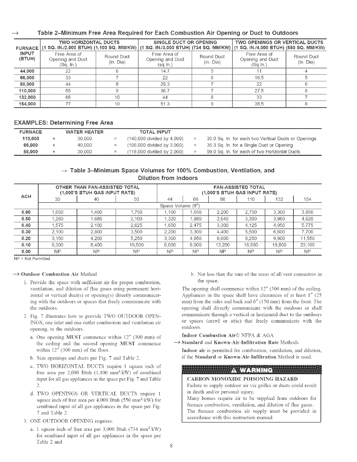
--> Table 2=Minimum Free Area Required for Each Combustion Air Opening or Duct to Outdoors
TWO HORIZONTAL DUCTS SINGLE DUCT OR OPENING TWO OPENINGS OR VERTRCAL DUCTS
FURNACE[ (1 SQ. IN.t2,000 BTUH) (1,100 SQ. MM/KW) (1 SQ. IN.i3,000 BTUH) (734 SQ. NNIKW) (1 $Q. IN./4,000 BTUH) (880 SQ. MM/KW)
INPUT Free Area of Free Area of Free Area of
{BTUH) Opening and Duct Round Duct Opening and Duct Round Duct Opening and Duct Round Duct
(Sq. in.) (in. Dia) (sq in.) (in. Dia) (Sq In.) (In. Dia)
44,000 22 6 14.7 5 11 4
88,000 33 7 22 6 16.5 5
88,000 44 8 29.3 7 22 6
110,000 55 9 36.7 7 27.5 6
132,000 66 10 44 8 33 7
184,000 77 10 51.3 9 38.5 8
EXAMPLES: Determining Free Area
FURNACE WATER HEATER TOTAL INPUT
110,000 + 30,000 (t40,000 divided by 4,000) 35.0 Sq. In. for each two Verticat Ducts or Openings
88,000 + 40,000 (106,000 divided by 3,000) 35.3 Sq. In. for a Singte Duct or Opening
88,000 + 30,000 (118,000 divided by 2,000) 59.0 Sq. In. for each of two Horizontal Ducts
--> Table 3=Minimum Space Volumes for 100% Combustion, Ventilation, and
Dilution from Indoors
OTHER THAN FAN=ASSISTED TOTAL FAN-ASSISTED TOTAL
(1,000'S BTUH GAS INPUT RATE) (1,000'S BTUH GAS INPUT RATE)
ACH 30 I 40 I 50 44 166 I 88 1110 I 132 1154
Space Volume (ft3)
0.80 1,050 1,400 1,750 1,100 1,650 2,200 2,750 3,300 3,850
0.80 1,260 1,680 2,100 1,320 1,980 2,640 3,300 3,960 4,620
0.40 1,575 2,100 2,625 1,650 2,475 3,300 4,125 4,950 5,775
0.30 2,100 2,800 3,500 2,200 3,300 4,400 5,500 6,600 7,700
0.20 3,150 4,200 5,250 3,300 4,950 6,600 8,250 9,900 11,550
0.10 6,300 8,400 10,500 6,600 9,900 13,200 16,500 19,800 23,100
0.00 NP NP NP NP NP NP NP NP NP
NP = Not Permitted
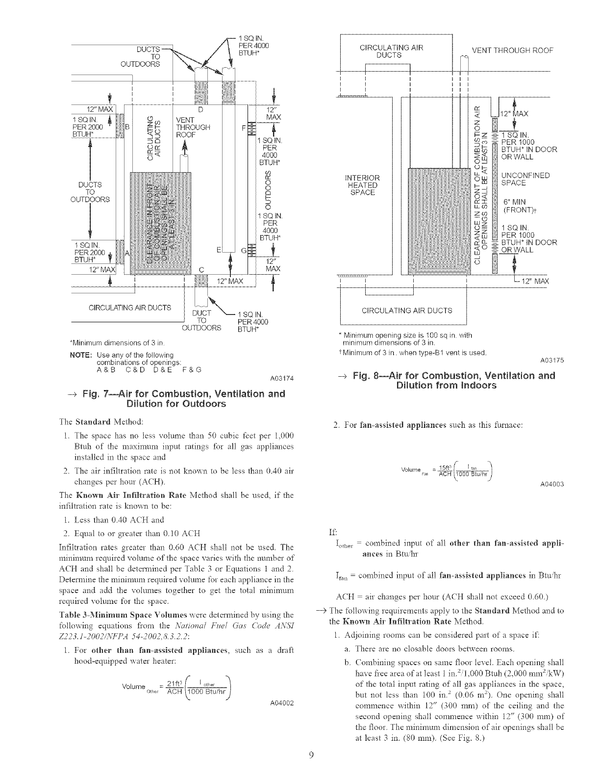
---> Outdoor Combustion Air Method
1. Provide the space with sufficient air _br proper combustion,
ventilation, and dilution of flue gases using permanent hori=
zontal or vertical duct(s) or opening(s) directly communicat=
ing with the ontdoors or spaces that freely communicate with
the ontdoors.
2. Fig. 7 illustrates how to provide TWO OUTDOOR OPEN°
INGS, one inlet and one outlet combustion and ventilation air
opening, to the outdoors.
a. One opening MUST commence within 12" (300 ram) of
the ceiling and the second opening MUST commence
within 12" (300 ram) of the floor.
b. Size openings and ducts per Fig. 7 and Table 2.
c. TWO HORIZONTAL DUCTS require 1 square inch of
flee area per 2,000 Bmh (1.100 mm2ikW) of combined
input fbr all gas appliances in the space per Fig. 7 and Table
2.
d. TWO OPENINGS OR VERTICAL DUCTS require 1
square inch of flee area per 4,000 Bmh (550 mm2ikW) for
combined input of all gas appliances in the space per Fig.
7 and Table 2.
3. ONE OUTDOOR OPENING requires:
a. 1 square inch of flee area per 3,000 Btuh (734 mm2&W)
for combined input of all gas appliances in the space per
Table 2and
b. Not less than the sum of the areas of all vent connectors in
the space.
The opening shall commence within 12" (300 ram) of the ceiling.
Appliances in the space shall have clearances of at least 1" (25
ram) fiom d-_esides and back and 6" (150 ram) from the front. The
opening shall directly communicate with the outdoors or shall
communicate through a vertical or horizontal duct to d_e outdoors
or spaces (crawl or attic) that fieely communicate with the
outdoors.
Indoor Combustion Air<) NFPA & AGA
---> Standard and Known-Air-Infiltration Rate Methods
Indoor air is permitted fbr combustion, ventilation, and dilution,
if the Standard or Known=Air-Infiltration Method is used.
CARBON MONOXIDE POISONING HAZARD
Failure to supply outdoor air via grilles or ducts could result
in death and/or personal injury.
Many homes require air to be supplied from outdoors for
furnace combustion, ventilation, and dilution of flue gases.
The /'umace combustion air supply must be provided in
accordance with this instruction manual.
TO
OUTDOORS
PER4000
BTUH*
t
12" MAX
1 SQ IN A
PER2000
BTUH*
DUCTS
TO
OUTDOORS
1 SQ IN.
PER 2000
BTUH I[
12 _
MAX
SQ tN
PER
4000
BTUH*
c0
8d
o
o
S
o
1 SO iN.
PER
4000
BTUH*
12 _
MAX
CIRCULATING AIR DUCTS
TO
OUTDOORS
*Minimum dimensions of 3 in
NOTE: Use any of the following
combinations of openings:
A&B C&D D&E F&G
1 SQ IN.
PER 4000
BTUH*
A03174
-> Fig. 7--Air for Combustion, Ventilation and
Dilution for Outdoors
I CIRCULATING AIR
DUCTS
-r
I I
I I
I I
INTERIOR
HEATED
SPACE
] VENT THROUGH ROOF
I I
I I
I I LJl .L
i
1 SO IN.
" PER 1000
BTUH* IN DOOR
OR WALL
UNCONFINED
SPACE
6" M[N
(FRONT)t
1 SQ IN.
PER 1000
: BTUH* tN DOOR
OR WALL
]l CIRCULATING AIR DUCTS
12" MAX
* Minimum opening size is 100 sq in with
minimum dimensions of 3 in.
t Minimum of 3 in. when type-B1 vent is used. A03175
-> Fig. 8--Air for Combustion, Ventilation and
Dilution from indoors
The Stalidard Method:
1. The space has no tess volume than 50 cubic f'cet per 1.000
Bmh of the maximum input ratings for all gas appliances
installed in the space and
2. The air infiltration rate is not known to be less than 0.40 air
changes per hour (ACH)
The Kno_n Air Infiltration Rate Method shall be used. if the
infiltration rate is known to be:
1. Less than 0.40 ACH and
2. Equal to or greater than 0.10 ACH
Infiltration rates greater than 0.60 ACH shall not be used. The
mininlum required volume of the space varies with the number of
A(H and shall be detem_ined per Table 3 or Equations 1 and 2.
Determine the mininmm required volume for each appliance in the
space and add the volumes together to get the total n_inin-mm
required volume for the space.
Table 3-Minimum Space Volumes were determined by using the
following equations fiom the Yationa/ F_el Gas Cn&_ zl:\i_7
Z223./-2002/iVFP_ 54-2002.&3.2.2:
1. For other than fan-assisted appliances, such as a draft
hood-equipped water heater:
21fts _ I °tt'er }/
Volumeother = A-==0_p0_} B-_/hr)
A04002
2. For fan-assisted appliances such as this fk/rnace:
_ 15fls Iran
VolumeFa n - __
A04003
If:
Ioti_ = combined input of all other than fan-assisted appli-
ances in Btuhr
I_.,, =combined input of all fan-assisted appliances in Btuhr
ACH air changes per hour (ACH shall not exceed 0.d0.)
--> The following requirements apply to the Standard Method and to
the Known Air Infiltration Rate Method
1. Adjoining rooms can be considered part of a space if!
a. There are no closable doors between rooms.
b. (ombining spaces on same floor level. Each opening shall
have fiee area of at least 1 in.2/1.000 Btuh (2.000 mm2ikW)
of the total input rating of all gas appliances in the space.
but not less than 100 in. 2 (0.0d m2). One opening shall
commence within 12" (300 ram) of the ceiling and the
second opening shall commence within 12" (300 ram) of
the floor. The minimum dimension of air openings shall be
at least 3 in. (80 ram). (See Fig. S.)
c.( ornbiningspaceondiff?rentfloorlevels.Thevolumesof
spacesondifferentfloorlevelsshallbeconsideredas
communicatingspacesif connectedbyoneormoreperma=
nentopeningsindoorsorfloorshavingfi'eeareaofatleast
2in.2/1,000 Bmh (4,400 mma&W) of total input rating of
all gas appliances.
2. An attic or crawlspace may be considered a space that fieely
communicates with the outdoors provided there are adequate
pet_nanent ventilation openings directly to outdoors having
_?ee area of at least i-in.2/4,000 Bmh of total input rating for
all gas appliances in the space.
3. In spaces that use tlle Indoor Combustion Air Method,
infiltration should be adequate to provide air for combustion,
pemlanent ventilation and dilution of flue gases. However, in
buildings with unusually tight construction, additional air
MUST be provided using the methods described in the
Outdoor Combustion Air Method section.
Unusually tight construction is defined as
Construction with:
a. Walls and ceilings exposed to the outdoors have a continu=
ous_ sealed vapor barrier. Openings are gasketed or sealed
and
b. Doors and openable windows are weatherstripped and
c. Other openings are caulked or sealed. These include joints
around window and door fi'ames, between sole plates and
floors, between wall-ceiling joints, between wall panels, at
penetrations _br plumbing, electrical and gas lines, etc.
---> Combination of Indoor and Outdoor Air
1. Indoor openings shall comply with tlle Indoor Combustion
Air Method below and,
2. Outdoor openings shall be located as required in tlle Outdoor
Combustion Air Method mentioned previously and,
3. Outdoor openings shall be sized as follows:
a. (alculate the Ratio of all Indoor Space volume divided by
required volume _br Indoor Combustion Air Method
below.
b. Outdoor opening size reduction Factor is 1 minus the
Ratio in a. above.
c. Minimum size of Outdoor openings shall be the size
required in Outdoor (ombusIiou Air Method above
nmltiplied by reduction Factor in b. above. The nlininlum
dimension of air openings shall be not tess than 3 in. (80
111111)
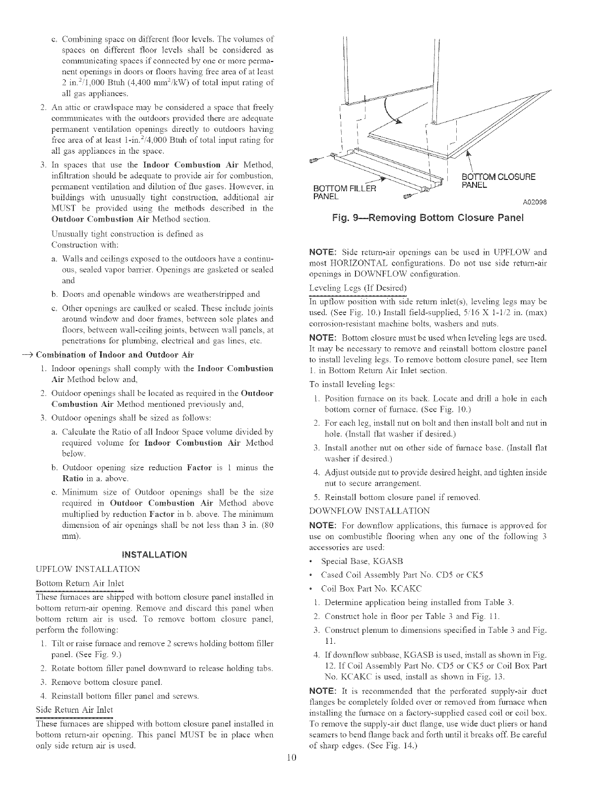
INSTALLATION
LPFLOW INSTALLATION
Bottom Return Air Inlet
These fhmaces are shipped with bottom closure panel installed in
bottom return-air opening. Remove and discard this panel when
bottom remm air is use& To remove bottom closure panel
perfbrrn die following:
1. Tilt or raise furnace and remove 2screws holding bottom filler
panel (See Fig. 9.)
2. Rotate bottom filler panel downward to release holding tabs.
3. Remove bottom closm'e panel
4. Reinstall bottom filler panel and screws
Side Return Air Inlet
These fk/rnaces are shipped with bottom closure panel installed in
bottom return=air opening. This panel MUST be in place when
only side remm air is used.
BOTTOM FILLER
PANEL
I I
BOTTOM CLOSURE
PANEL
A02098
Fig. g--Removing Bottom Closure Panel
10
NOTE: Side return=air openings can be used in UPFLOW and
most HORIZONTAL coni:igurations Do not use side return-air
openings in DOWNFLOW configuration.
Leveling Legs (If Desired)
In upfluw position with side remm inlet(s), leveling legs may be
used. (See Fig. 10.) Install field=supplied, 5/16 X 1-1/2 in. (max)
con'osion-resistant machine bolts, washers and nuts.
NOTE: Bottom closure most be used when leveling legs are used.
It may be necessary to remove and reinstall bottom closure panel
to install leveling legs. To remove bottom closure panel, see Item
1. in Bottom Return Air Inlet section.
To install leveling legs:
1. Position furnace on its back. Locate and drill a hole in each
bottom corner of fi/mace. (See Fig. 10.)
2. For each leg, install nut on bolt and then install bolt and nut in
hole. (Install flat washer if desired.)
3. Install another nut on other side of fi/rnace base. (Install flat
washer if desired.)
4. Adjust outside nut to provide desired height, and tighten inside
nut to secure arrallgement.
5. Reinstall bottom closure panel if removed.
DOVvL\'FLOW INSTALLATION
NOTE: For downflow applications, this furnace is approved fbr
use on combustible flooring when any one of the following 3
accessories are used:
° Special Base, KGASB
° Cased (oil Assembly Part No. (D5 or (K5
° (?oil Box Part No. KCAKC
1. Determine application being installed from Table 3.
2. (onstruct hole in floor per Table 3 and Fig. 11.
3. (onstruct plenum to dimensions specified in Table 3 and Fig.
11.
4. If downfluw subbase, KOASB is used, install as shown in Fig.
12. If Coil Assernbly Part No. (D5 or (K5 or (Toil Box Part
No. K(AKC is used, install as shown in Fig. 13.
NOTE: It is recommended that the perI:brated supply-air duct
flanges be completely _blded over or removed flora fi_rnace when
installing the _i/rnace on a fhctory-supplied cased coil or coil box.
To remove the supply-air dact flange, use wide duct pliers or hand
seamers to bend flange back and _:Prth until it breaks of LBe careful
of sharp edges. (See Fig. 14.)
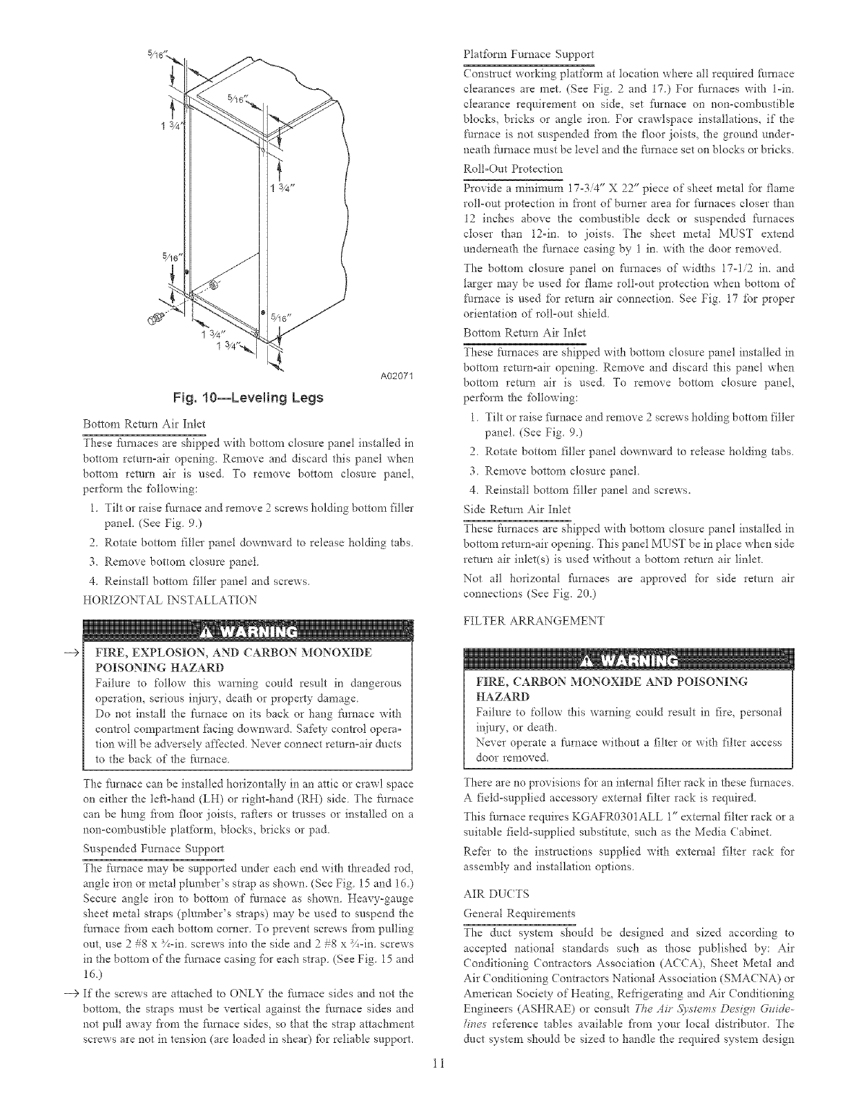
/4 t,
A02071
Fig. 10--Leveling Legs
Bottom Return Air Inlet
These furnaces are shipped with bottom closure panel installed in
bottom return=air opening. Remove and discard this panel when
bottom return air is used. To remove bottom closure panel,
perfbrm the following:
1. Tilt or raise furnace and remove 2screws holding bottom filler
panel. (See Fig. 9.)
2. Rotate bottom filler panel downward to release holding tabs.
3. Remove bottom closure panel.
4. Reinstall bottom filler panel and screws.
HORIZONTAL INSTALLATION
--€ FIRE, EXPLOSION, AND CARBON MONOXIDE
POISONING HAZARD
Failure to follow this warning could result in dangerous
operation, serious injury, death or property damage
Do not instal1 the fttrnace on its back or hang fimaace with
control compartment facing downward. Safety control opera=
tion will be adversely affected. Never connect return=air ducts
to the back of the furnace.
The furnace car* be installed horizontally in an attic or crawl space
on either the left-hand (LH) or right=hand (RH) side The furnace
can be hung fiom floor joists, rafters or trusses or installed on a
non-combustible platfbrm, blocks, bricks or pad.
Suspended Furnace Suppmq _
The furnace may be supported under each end with threaded rod,
angle iron or metal plumber's strap as shown. (See Fig. 15 and 16.)
Secure angle iron to bottom of l\tmace as shown. Heavy-gauge
sheet metal straps (plumber's straps) may be used to suspend the
furnace fiom each bottom corner. To prevent screws fiom pulling
out, use 2#S x _/_-in. screws into the side and 2 #8 x -%-in. screws
in the bottom of the fhmace casing for each strap. (See Fig. 15 and
16,)
--> If the screws are attached to ONLY the fitmace sides and not the
bottom, the straps must be vertical against the fm'nace sides and
not pull away fiom the f_amace sides, so that the strap attachment
screws are not in tension (are loaded in shear) for reliable support,
Platfbrm Furnace Support
Construct working platform at location where all required furnace
clearances are met. (See Fig 2and 17.) For furnaces with l-in.
clearance requirement on side, set fllmace on non=congbustible
blocks, bricks or angle iron For crawlspace installations, if the
fm'nace is not suspended fi'om the floor joists, the ground under-
neath furnace must be level and the furnace set on blocks or bricks.
Roll=Out Protection
Provide a minimum 17-3/4" X 22" piece of sheet metal for flame
roll-out protection in fi'ont of burner area for fhmaces closer than
12 inches above the combustible deck or suspended furnaces
closer than 12-in. to joists. The sheet metal MUST extend
underneath the fhmace casing by 1 in. with the door removed.
The bottom closure panel on furnaces of widths 17=i/2 in. and
larger may be used for flame roll-out protection when bottom of
furnace is used for remm air connection. See Fig. 17 for proper
orientation of roll=out shield.
Bottom Return Air Inlet
These ti_maces are shipped with bottom closure panel installed in
bottom return=air opening. Remove and discard this panel when
bottom remm air is used. To remove bottom closure panel,
perform the following:
1. Tilt or raise furnace and remove 2screws holding bottom filler
panel. (See Fig. 9.)
2. Rotate bottom filler panel downward to release holding tabs.
3. Remove bottom closure panel.
4. Reinstall bottom filler panel and screws.
Side Return Air Inlet
These furnaces are shipped with bottom closure panel installed in
bottom return=air opening. This panel MUST be in place when side
return air inlet(s) is used without a bottom return air linlet.
Not all horizontal furnaces are approved for side return air
connections (See Fig. 20.)
FILTER ARRANGEMENT
FIRE, CARBON MONOXIDE AND POISONING
HAZARD
Failure to %tlow this warning could result in fire, personal
injury, or death.
Never operate a fire, ace without a filter or with filter access
door removed.
There are no provisions for an internal filter rack in these fhrnaces.
A field=supplied accessory external filter rack is required.
This furnace requires KGAFR0301ALL 1" external filter rack or a
suitable field-supplied substitute, such as the Media Cabinet.
Refer to the instructions supplied with external filter rack for
assembly and installation options
AIR DLCTS
General Requirements
The duct system should be designed and sized according to
accepted national standards such as those published by: Air
Conditioning Contractors Association (ACCA), Sheet Metal and
Air Conditioning Contractors National Association (SMACNA) or
American Society of Heating, Refrigerating and Air Conditioning
Engineers (ASHRAE) or consuh Yhe Ai_' .5)'stems Desigr_ G_ide-
!i_ve.s reference tables available fi'om your tocal distributor. The
duct system should be sized to handle the required system design
11
FURNACE
CASRNG
WIDTH
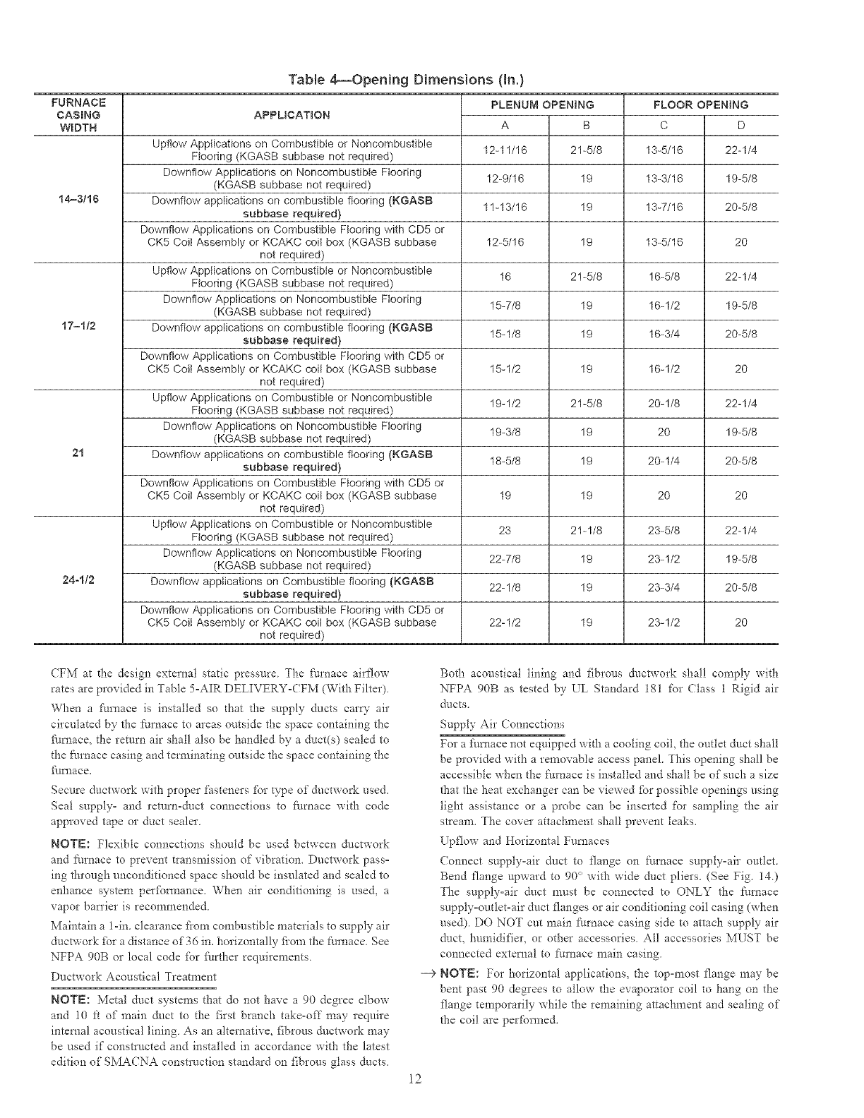
TaNe 4_Opening Dimensions (in.)
APPLICATION C
Upflow Applications on Combustible or Noncombustible
Flooring (KGASB subbase not required) 13-5/16
Downflow Applications on Noncombustible Flooring 13-3/16
(KGASB subbase not required)
t4-3/16 Downflow applications on combustible flooring (KGASB 13-7/16
subbase required)
Downflow Applications on Combustible Ftooring with CD5 or
CK5 Coil Assembly or KCAKC coil box (KGASB subbase 13-5/16
not required)
Upflow Applications on Combustible or Noncombustible 16-5/8
Flooring (KGASB subbase not required)
Downflow Applications on Noncombustible Flooring 16-1/2
(KGASB subbase not required)
17=1/2 Downflow applications on combustible flooring (KGASB 16-3/4
subbase required)
Downflow Applications on Combustible Ftooring with CD5 or
CK5 Coil Assembly or KCAKC coil box (KGASB subbase 16-1/2
not required)
Upflow Applications on Combustible or Noncombustible 20-1/8
Flooring (KGASB subbase not required)
Downflow Applications on Noncombustible Flooring 20
(KGASB subbase not required)
21 Downflow applications on combustible flooring (KGASB 20-1/4
subbase required)
Downflow Applications on Combustible Flooring with CD5 or
CK5 Coit Assembly or KCAKC coit box (KGASB subbase 20
not required)
Upflow Applications on Combustible or Noncombustible 23-5/8
Flooring (KGASB subbase not required)
Downflow Applications on Noncombustible Flooring 23-1/2
(KGASB subbase not required)
24-1/2 Downflow applications on Combustible flooring (KGASB 23-3/4
subbase required)
Downflow Applications on Combustible Ftoonng with CD5 or
CK5 Coil Assembly or KCAKC coil box (KGASB subbase 23-1/2
not required)
PLENUM OPENING
A B
12-11/16 21-5/8
12-9/16 19
11-13/16 19
12-5/16 19
16 21-5/8
15-7/8 19
15-1/8 19
15-1/2 19
19-1/2 21-5/8
19-%8 19
18-5/8 19
19 19
23 21-1/8
22-7/8 19
22-1/8 19
22-1/2 19
FLOOR OPENING
D
22-1/4
19-5/8
20-5/8
20
22-1/4
19-5/8
20-5/8
20
22-1/4
19-5/8
20-5/8
20
22-1/4
19-5/8
20-5/8
2O
(FM at d_e design external static pressure The furnace airflow
rates are provided in Table 5=AIR DELIVERY=( FM (With Filter)
When a J:\lmace is installed so that the supply ducts car_- air
circulated by the J:\_mace to areas outside the space containing the
_/rnace, the return air shall also be handled by a duct(s) sealed to
the furnace casing and terminating outside the space containing the
_/rnace.
Secure ductwork with proper fasteners for type of doctwork used.
Seal supply- and return-duct connections to _./rnace with code
approved tape or duct sealer.
NOTE: Flexible connections should be used between ductwork
and/_urnace to prevent transmission of vibration. Ductwork pass=
ing through unconditioned space should be insulated and sealed to
enhance system perfbrmance. When air conditioning is used, a
vapor barrier is recommended.
Maintain a l-in. clearance fiom combustible materials to supply air
ductwork for a distance of 36 in. horizontally fiom the Nmace. See
NFPA 90B or local code _br Nrther requirements.
Ductwork Acoustical Treatment
NOTE: Metal duct systems that do not have a 90 degree elbow
and 10 ft of main duct to the first branch take-off may require
internal acoustical lining. As an alternative, fibrous ductwork may
be used if constructed and installed in accordance with the latest
edition of SMACNA construction standard on fibrous glass ducts.
--€
12
Both acoustical lining and fibrous ductwork shall comply with
NFPA 90B as tested by _L Standard 181 for (?lass 1 Rigid air
ducts.
Supply Air Connections
For a f_u'nace not equipped with a cooling coil, the outlet duct shall
be provided with a removable access panel. This opening shall be
accessible when the furnace is installed and shall be of such a size
that the heat exchanger can be viewed fbr possible openings using
light assistance or a probe can be inserted for sampling the air
stream. The cover attachment shall prevent leaks.
Upflow and Horizontal Furnaces
(onnect supply-air duct to flange on fulnace supply=air outlet.
Bend flange upward to 90 ° with wide duct pliers (See Fig. 14)
The supply-air duct must be connected to ONLY the furnace
supply=outlet-air duct flanges or air conditioning coil casing (when
used) DO NOT cut main J:_m'nace casing side to attach supply air
duct, humidifier, or other accessories All accessories MI_ST be
connected external to furnace main casing
NOTE: For horizontal applications, the top-most flange may be
bent past 90 degrees Go allow d_e evaporator coil to hang on the
flange temporarily while the remaining attachment and sealing of
the coil are performed.
FURNACE
(OR COIL CASING
WHEN USED)
COMBUSTIBLE
FLOORING
SUBBASE
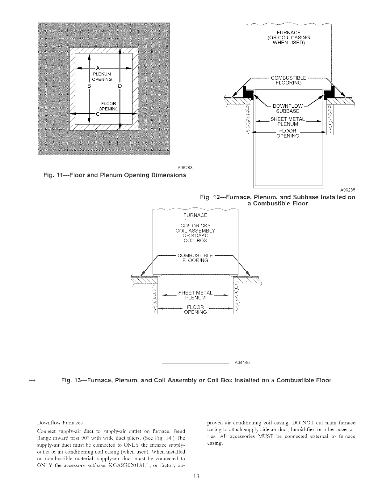
PLENUM
__ FLOOR __
OPENING
A96283
Fig. 11--Floor and Plenum Opening Dimensions
A96285
Fig. 12--Furnace, Plenum, and Subbase InstNted on
a Combustible Floor
FURNACE
CD5 OR CK5
COIL ASSEMBLY
OR KCAKC
COIL BOX
COMBUSTIBLE
FLOORING
SHEET METAL _
PLENUM
FLOOR
OPENING
A04140
___> Fig. 13--Furnace, Plenum, and Coil AssemNy or Coil Box Installed on a Combustible Floor
Downflow Furnaces
Connect supply-air duct to supply-air outlet on _iu_ace. Bend
flange inward past 90 ° with wide duct pliers_ (See Fig. 14.) The
supply=air duct must be connected to ONLY the fi/rnace supply=
outlet or air conditioning coil casing (when used). When installed
on combustible material, supply-air duct must be connected to
ONLY the accessory subbase, KGASB0201ALL, or _Sctory ap=
proved air conditioning coil casing. DO NOT cut main furnace
casing to attach supply side air duct, humidifier, or other accesso-
ries. All accessories MUST be connected external to furnace
casing.
13
UPFLOW
PREFERRED
DOWNFLOW
i i PREFERRED
HORIZONTAL
I.....
PREFERRED 120_.
M_N
PREFERRED
PERMITTED i PERMITTED
i
i
IJ
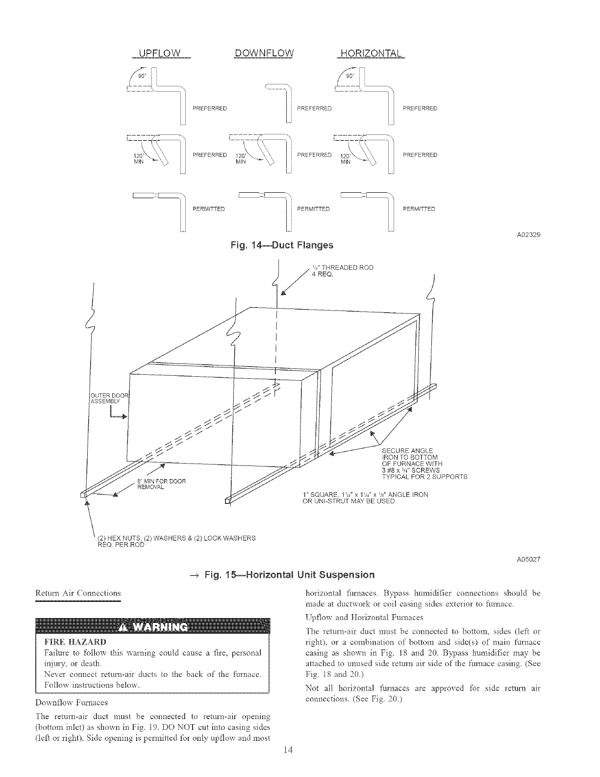
Fig. 14--Duct Flanges
PERMITTED
W' THREADED ROD
4 REQ
I
I
I
I
I
A02329
<
SECURE ANGLE
IRON TO BOTTOM
OF FURNACE WITH
3 #8 x s/4"SCREWS
TYPICAL FOR 2 SUPPORTS
1" SQUARE, 1W' x 1W' x %" ANGLE IRON
OR UNI-STRUT MAY BE USED
(2) HEX NUTS, (2)WASHERS & (2) LOCK WASHERS
REQ PER ROD
A05027
-_ Fig. 18--Horizontal Unit Suspension
Return Air Connections
FIRE HAZARD
Failure to %l!ow this warning could cause a fire, personal
injury, or death
Never connect return-air ducts to the back of the ftmaace
Follow instl-t/ctions below.
DownJ:low Furnaces
The return=air duct must be connected to return-air opening
(bottom inlet) as shown in Fig. 19. DO NOT cut into casing sides
(left or right). Side opening is pem_itted for only upflow and most
horizontal Parnaces. Bypass humidifier connections should be
made at ductwork or coil casing sides exterior to ft_rnace
Upflow and Horizontal Furnaces
The return-air duct must be connected to bottom, sides (left or
right), or a combination of bottom and side(s) of main furnace
casing as shown in Fig lg and 20. Bypass l"mmidi_]er may be
attached to unused side return air side of the [:tm_ace casing (See
Fig lg and 20.)
Not all horizontal fm'naces are approved for side return air
connections. (See Fig 20.)
14
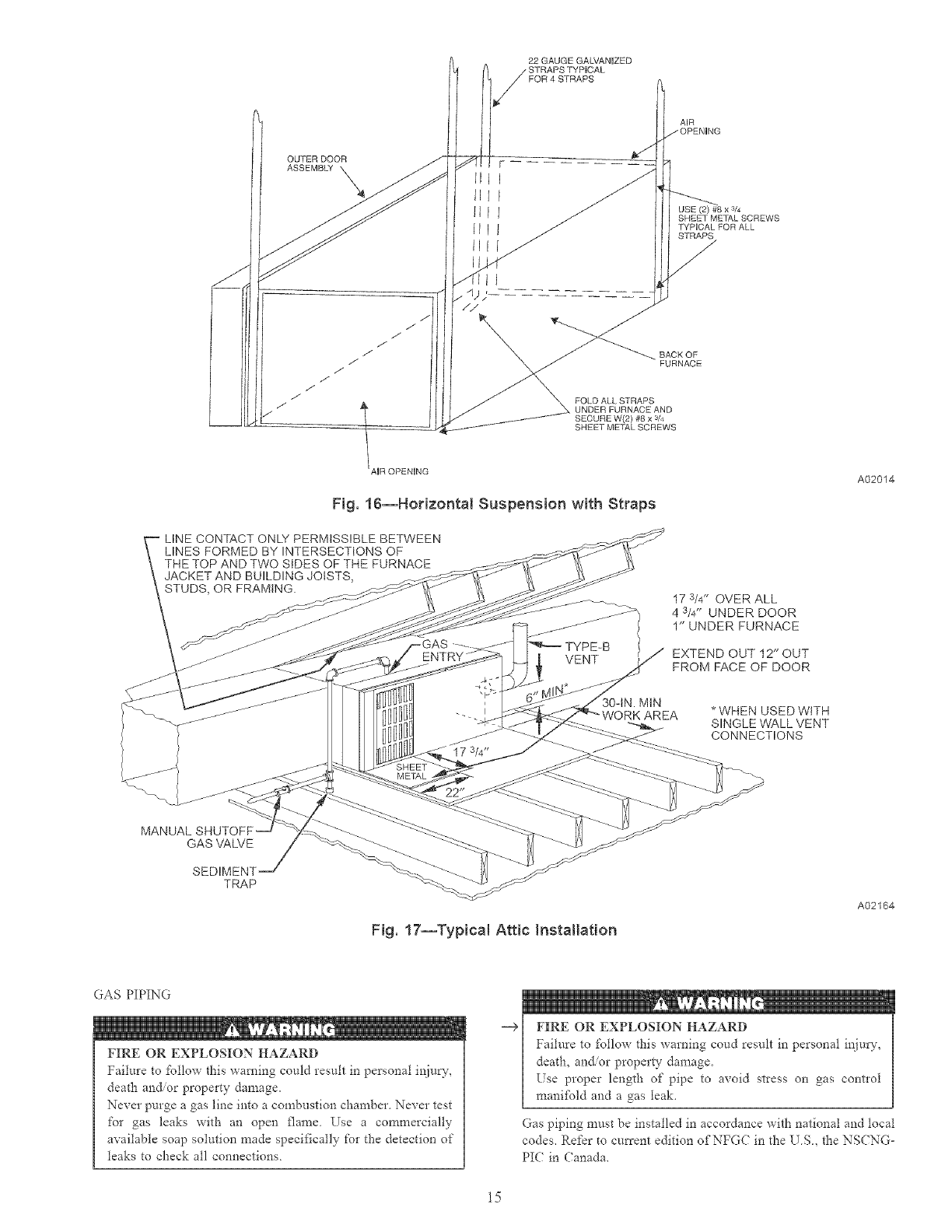
22 GAUGE GALVANIZED
FOR 4 STRAPS
x 3/4
SHEET METAL SCREWS
TYPICAL FOR ALL
STRAPS
BACK OF
FURNACE
FOLD ALL STRAPS
UNDER FURNACE AND
SECURE W(2) #8 x 3/4
SHEET METAL SCREWS
Fig. 16--HorizontN Suspension with Straps
LINE CONTACT ONLY PERMISSIBLE BETWEEN
LINES FORMED BY INTERSECTIONS OF
A02014
STUDS, OR FRAMING.
30-tN. MIN
17 s/4" OVER ALL
4 3/4" UNDER DOOR
1" UNDER FURNACE
EXTEND OUT t2'* OUT
FROM FACE OF DOOR
* WHEN USED WITH
SINGLE WALL VENT
CONNECTIONS
GAS VALVE
SEDIMENT j
TRAP
Fig. 17--Typical Attic Installation
A02164
GAS PIPING
,iU
_. iiiiiil
FIRE OR EXPLOSION HAZARD
Failure to l'ollow this warning could result in personal injury,
deatl-_ and/or property damage,
Never purge a gas line into a combustion chamber Never test
for gas leaks with an open flame Use a commercially
available soap solution made specifically for the detection of
leaks to check all connections.
--+ FIRE OR EXPLOSION HAZARD
Failure to %llow this warning coud result in personal inju W,
death, and/or property damage,
Ese proper length of pipe to avoid stress on gas contloi
maniR_ld and a gas leak,
Gas piping must be installed in accordance with national and tocal
codes. Refer to current edition of NFG( in the US, the NSCNG-
PIC in Canada,
15
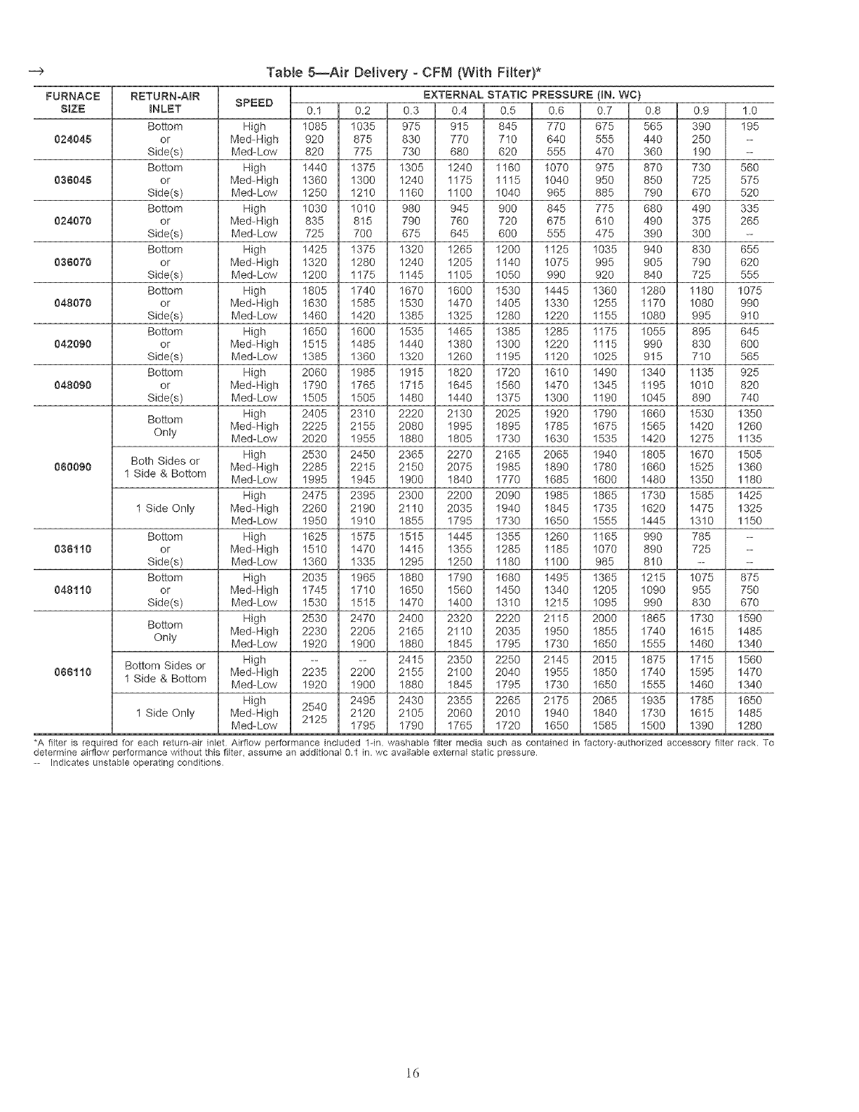
-4_ Table 5--Air Delivery - CFM (With Filter)*
FURNACE
SIZE
024045
038049
024070
038070
048070
042090
048090
080090
038110
048110
099110
RETURN-AIR
INLET
Bottom
or
Side(s)
Bottom
or
Side(s)
Bottom
or
Bide(s)
Bottom
or
Side(s)
Bottom
or
Side(s)
Bottom
or
Bide(s)
Bottom
or
Side(s)
Bottom
Only
Both Sides or
1 Side & Bottom
1 Side Only
Bottom
or
Bide(s)
Bottom
or
Side(s)
Bottom
Only
Bottom Sides or
1 Side & Bottom
1 Side Only
EXTERNAL STATIC PRESSURE (_N. WC)
SPEED 0.1 0.2 0.3 0.4 0.5 0.6 0.7 0.8 0.9 1.0
High 1085 1035 975 915 845 770 675 565 390 195
Med-High 920 875 830 770 710 640 555 440 250 --
Med-Low 820 775 730 680 620 555 470 360 190 --
High 1440 1375 1305 1240 1160 1070 975 870 730 560
Med-High 1360 1300 1240 1175 1115 1040 950 850 725 575
Med-Low 1250 1210 1160 1100 1040 965 885 790 670 520
High 1030 1010 980 945 900 845 775 680 490 335
Med-High 835 815 790 760 720 675 610 490 375 265
Med_Low 725 700 675 645 600 555 475 390 300 --
High 1425 1375 1320 1265 1200 1125 1035 940 830 655
Med-High 1320 1280 1240 1205 1140 1075 995 905 790 620
Med-Low 1200 1175 1145 1105 1050 990 920 840 725 555
High 1805 1740 1670 1600 1530 1445 1360 1280 1180 1075
Med-High 1630 1585 1530 1470 1405 1330 1255 1170 1080 990
Med-Low 1460 1420 1385 1325 1280 1220 1155 1080 995 910
High 1650 1600 1535 1465 1385 1285 1175 1055 895 645
Med-High 1515 1485 1440 1380 1300 1220 1115 990 830 600
Med-Low 1385 1360 1320 1260 1195 1120 1025 915 710 565
High 2060 1985 1915 1820 1720 1610 1490 1340 1135 925
Med-High 1790 1765 1715 1645 1560 1470 1345 1195 1010 820
Med-Low 1505 1505 1480 1440 1375 1300 1190 1045 890 740
High 2405 2310 2220 2130 2025 1920 1790 1660 1530 1350
Med-High 2225 2155 2080 1995 1895 1785 1675 1565 1420 1260
Med-Low 2020 1955 1880 1805 1730 1630 1535 1420 1275 1135
High 2530 2450 2365 2270 2165 2065 1940 1805 1670 1505
Med-High 2285 2215 2150 2075 1985 1890 1780 1660 1525 1360
Med-Low 1995 1945 1900 1840 1770 1685 1600 1480 1350 1180
High 2475 2395 2300 2200 2090 1985 1865 1730 1585 1425
Med-High 2260 2190 2110 2035 1940 1845 1735 1620 1475 1325
Med-Low 1950 1910 1855 1795 1730 1650 1555 1445 1310 1150
High 1625 1575 1515 1445 1355 1260 1165 990 785 --
Med_High 1510 1470 1415 1355 1285 1185 1070 890 725 --
Med-Low 1360 1335 1295 1250 1180 1100 985 810 ....
High 2035 1965 1880 1790 1680 1495 1365 1215 1075 875
Med-High 1745 1710 1650 1560 1450 1340 1205 1090 955 750
Med-Low 1530 1515 1470 1400 1310 1215 1095 990 830 670
High 2530 2470 2400 2320 2220 2115 2000 1865 1730 1590
Med-High 2230 2205 2165 2110 2035 1950 1855 1740 1615 1485
Med-Low 1920 1900 1880 1845 1795 1730 1650 1555 1460 1340
High .... 2415 2350 2250 2145 2015 1875 1715 1560
Med-High 2235 2200 2155 2100 2040 1955 1850 1740 1595 1470
Med-Low 1920 1900 1880 1845 1795 1730 1650 1555 1460 1340
High 2540 2495 2430 2355 2265 2175 2065 1935 1785 1650
Med-High 2125 2120 2105 2060 2010 1940 1840 1730 1615 1485
Med-Low 1795 1790 1765 1720 1650 1585 1500 1390 1280
*A filter is required for each return-air inlet Airflow performance included 1-in. washable filter media such as contained in factory-authorized accessory fi{ter rack. To
determine airflow pedormance without this filter, assume an additional 0 1 in. wc available external static pressure
-- Indicates unstable operating conditions
16
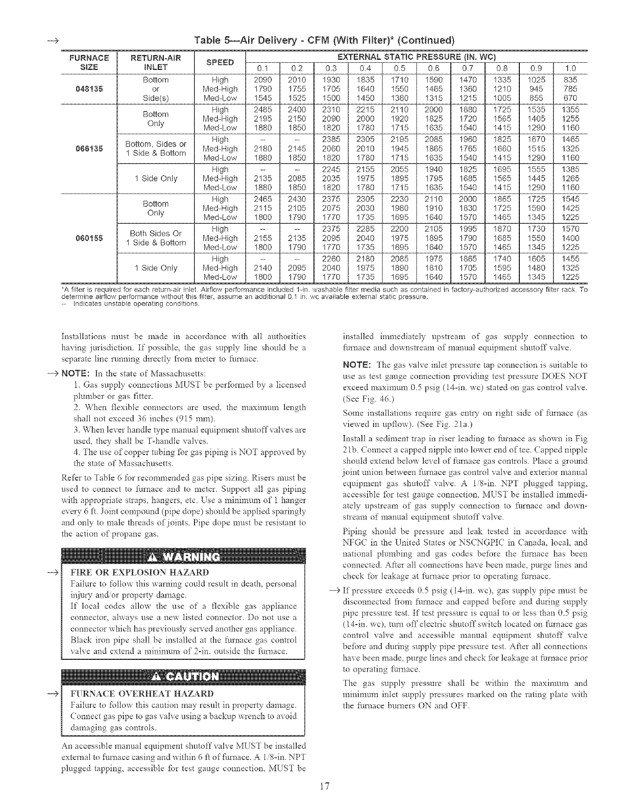
-+ Table5--Air Delivery - CFM (With Filter)* (Continued)
FURNACE
SIZE
048185
868135
080155
RETURNoA_R
INLET
Bottom
or
Side(s)
Bottom
Onty
Bottom, Sides or
1 Side & Bottom
1 Side Only
Bottom
Onty
Both Sides Or
1 Side & Bottom
1 Side Only
SPEED EXTERNAL STATIC PRESSURE (IN. WC)
0.1 0.2 0.3 0.4 0.5 0.6 0.7 0.8 0.9 1.0
High 2090 2010 1930 1835 1710 1590 1470 1335 1025 835
Med-High 1790 1755 1705 1640 1550 1465 1360 1210 945 785
Med-Low 1545 1525 1500 1450 1380 1315 1215 1005 855 670
High 2485 2400 2310 2215 2110 2000 1880 1725 1535 1355
Med-High 2195 2150 2090 2000 1920 1825 1720 1565 1405 1255
Med-Low 1880 1850 1820 1780 1715 1635 1540 1415 1290 1160
High .... 2385 2305 2195 2085 1960 1825 1670 1465
Med-High 2180 2145 2060 2010 1945 1865 1765 1660 1515 1325
Med-Low 1880 1850 1820 1780 1715 1635 1540 1415 1290 1160
High .... 2245 2155 2055 1940 1825 1695 1555 1385
Med-High 2135 2085 2035 1975 1895 1795 1685 1565 1445 1265
Med-Low 1880 1850 1820 1780 1715 1635 1540 1415 1290 1160
High 2465 2430 2375 2305 2230 2110 2000 1865 1725 1545
Med-High 2115 2105 2075 2030 1980 1910 1830 1725 1590 1425
Med-Low 1800 1790 1770 1735 1695 1640 1570 1465 1345 1225
High .... 2375 2285 2200 2105 1995 1870 1730 1570
Med-High 2155 2135 2095 2040 1975 1895 1790 1685 1550 1400
Med-Low 1800 1790 1770 1735 1695 1640 1570 1465 1345 1225
High .... 2260 2180 2085 1975 1865 1740 1605 1455
Med-High 2140 2095 2040 1975 1890 1810 1705 1595 1480 1325
Med-Low 1800 1790 1770 1735 1695 1640 1570 1465 1345 1225
*A filter is required for each return-air inlet Airflow performance included lqn washable filter media such as contained in factory-authorized accessory filter rack To
determine airflow performance without this fi{ter, assume an additional 01 in wc available external static pressure.
Indicates unstable operating conditions.
Installations must be made in accordance with all authorities
having jurisdiction. If possible, the gas supply line should be a
separate line running directly fi'om meter to f_/ruace.
--> NOTE: In the state of Massachusetts:
1. Gas supply connections MUST be per_brmed by a licensed
plumber or gas fitter
2. When flexible connectors are used, the maximum length
shall not exceed 36 inches (915 ram).
3. When lever handle type manual equipment shutoff valves are
used, they shall be T-handle valves.
4. The use of copper robing _br gas piping is NOT approved by
the state of Massachusetts.
Refer to Table 6 for recommended gas pipe sizing Risers must be
used to connect to fiu'nace and to meter. Support all gas piping
with appropriate straps, hangers, etc. Use a minimum of 1 hanger
every 6 J:'t.Joint compound (pipe dope) should be applied sparingly
and only to male threads of joints. Pipe dope must be resistant to
the action of propane gas.
--€ FIRE OR EXPLOSION HAZARD
Failure to %llow this warning could result in death, personal
injury an_or property damage.
If local codes allow the use of a flexible gas appliance
connector, always use a new listed connector. Do not use a
connector which has previously served another gas appliance
Black iron pipe shall be installed at the furnace gas control
valve and extend a minimum of 2-in outside the f_/rnace.
installed immediately upstleam of gas supply connection to
furnace and downstream of manual equipment shutoff valve.
NOTE: The gas valve inlet pressuie tap connection is suitable to
use as test gauge connection providing test pressure DOES NOT
exceed maximum 0.5 psig (14-in. we) stated on gas control valve.
(See Fig. 46.)
Some installations require gas entry on right side of ftmaace (as
viewed in upflow). (See Fig. 21a.)
Install a sediment trap in riser leading to fitrnace as shown in Fig
2 lb. ( onnect a capped nipple into lower end of tee. ( upped nipple
should extend below level of furnace gas controls. Place a ground
joint union between tk_rnace gas control valve and exterior manual
equipment gas shutoff valve. A 1/8-in. NPT plugged tapping,
accessible fbr test gauge connection. MUST be installed immedi-
ately upstream of gas supply connection to fi/mace and down-
sheam of manual equipment shutoff valve.
Piping should be pressure and leak tested in accordance with
NFG( in the United States or NSCNGPIC in Canada, local, and
national plumbing and gas codes before the Nrnace has been
connected. After all connections have been made. purge lines and
check for leakage at fi/ruace prior to operating ft_mace.
--> If pressure exceeds 0.5 psig (14-in. wc), gas supply pipe must be
disconnected fi'om Nmace and capped before and during supply
pipe pressure test. If test pressure is equal to or less than 0.5 psig
(14-in. wc), turn off electric shutoff switch located on Nruace gas
conhol valve and accessible manual equipment shutoff valve
before and during supply pipe pressure test. After all connections
have been made, purge lines and check for leakage at furnace prior
to operating [:tm_ace.
The gas supply pressure shall be within the maximum and
mininmm inlet supply pressures marked on the rating plate with
the f_./ruace burners ON and OFF.
An accessible manual equipment shutoff valve MUST be installed
external to fi_mace casing and within 6 ft of fi/mace. A 1/8-in. NPT
plugged tapping, accessible fbr test gauge connection_ MUST be
17
R_TU_N
AIR
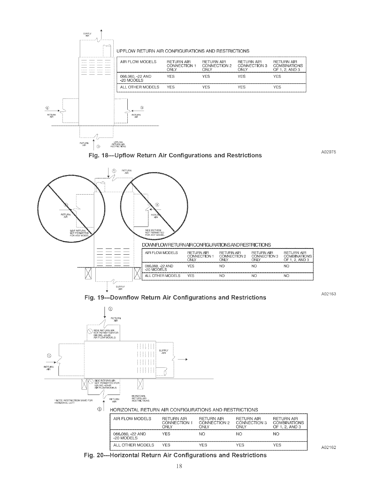
UPFLOW RETURN AR CONFiGURATiONS AND RESTRiCTiONS
AIR FLOW MODELS RETURN AIR RETURN AIR RETURN AIR RETURN AIR
CONNECTION 1 CONNECTION 2 CONNECTION 3 COMBIN,_]IONS
ONLY ONLY ONLY OF 1, 2, AND 3
06&060, _22 AND YES YES YES YES
"20 MODELS
ALL OTHER MODELS YES YES YES YES
i _ETU_N
i//.
Fig. 18--Upflow Return Air Configurat{ons and Restrictions A02075
EX_VNFLOWREq%IRNAmRCONFmGURATONSANDRESTR_CT_::)NS
AUR FLOW MODELS RETURN AUR RETURN AUR RETURN AUR RETURN AR
CONNEC]ION 1 CONNECTUON 2 CONNECTUON 3 COMBUN,_TIONS
ONLY OND/ ONLY OF 1, 2, AND 3
066.060, -22 AND YES NO NO NO
-20 MODELS
ALL OTHER MODELS YES NO NO NO
Fig. 19--Downflow Return Air Configurations and Restrictions
®
A02163
. 'i !J
"_ SliDERETURNA_R /
C_6O60-22-2O i ' i
' HORIZONA L
RETURN R URNA_R
HORIZONAL•NOTE RESTRICTIONE?_ SAME FOr_ _ A_R RESTR_CTIONS
@ | HORIZONTAL RETURN A_RCONFIGURATIONS AND RESTRICTIONS
A_R FLOW MODELS RETURN AIR RETURN A_R RETURN A_R RETURN A_R
CONNECTION 1 CONNECTION 2 CONNECTION 3 COMBiNATiONS
ONLY ONLY ONLY OF 1,2_ AND 3
066.060, -22 AND YES NO NO NO
-20 MODELS
ALL OTHER MODELS YES YES YES YES
Fig. 20--Horizonta{ Return Air Configurations and Restrictions
lg
A02162
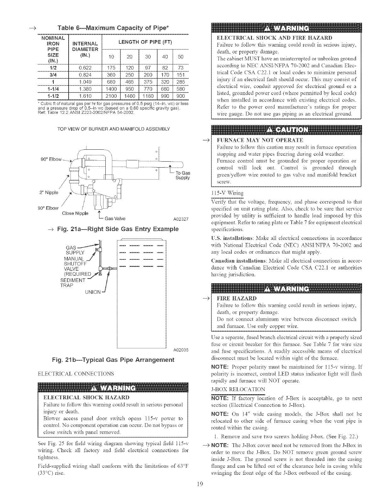
-+ Table 6--Ma×imum Capacity of Pipe*
NOMINAL
IRON
PIPE
SIZE
(BN.)
1/2
3/4
1
1-1/4
1-tt2
iNTERNAL
DIAMETER
(N.)
0.622
0.824
1.049
1.380
1.610
LENGTH OF PRPE (FT}
10 20 30 40 50
175 120 97 82 73
360 250 200 170 151
680 465 375 320 285
1400 950 770 660 580
2100 1460 1180 990 900
* Cubic ft of natural gas per hr for gas pressures of 0.5 psig (14-in. wc) or less
and a pressure drop of 0.5-in wc (based on a 0.60 specific gravity gas)
Ref: TaMe 122 ANSI Z223-2002/NFPA 54-2002
ELECTRICAL SHOCK AND FIRE HAZARD
Failure to follow this warning could result in serious inju U,
death, or property damage.
The cabinet MUST have an uninterrupted or unbroken ground
according to NEC ANSI NFPA 70-2002 and Canadian Elec=
tdcal (7ode CSA (22.1 or local codes to minimize personal
injury if an electrical _Sult should occur. This may consist of
electrical wire, conduit approved for electrical ground or a
listed, grounded power cord (where permitted by local code)
when installed in accordance with existing electrical codes.
Refer to the power cord manufacturer's ratings for proper
wire gauge. Do not use gas piping as an electrical ground.
TOP VEW OF BURNER AND MANIFOLD ASSEMBLY
2" Nipple
To Gas
Supply
90° Elbow /
Close NippBe L Gas Valve A02327
--_ Fig. 2In--Right Side Gas Entry Example
/.
GAS
SUPPLY j'_
MANUAL =J II
SHUTOFF £ _
VALVE :D _:_=
(REQUIRED/#',
SEDIMENT --
TRAP /
UNION -_
A02035
Fig. 21b--Typical Gas Pipe Arrangement
ELECTRICAL CONNECTIONS
ELECTRICAL SHOCK HAZARD
Failure to _bllow this warning could result in serious personal
in.ju_ or death.
Blower access panel door switch opens l15=v power to
control No component operation can occur. Do not bypass or
close switch with panel removed.
See Fig 25 %r field wiring diagram showing typical field 115-v
wiring. Check all factoQ' and field electrical connections for
tighmess,
Field=snpplied wiring shall con£_m_ with the limitations of 63°F
(33°C) rise
---> F[ RNACE MAY NOT OPERATE
Failure to _bllow this caution may result in £u'nace operation
stopping and water pipes fi'eezing during cold weather
Furnace control must be grounded _br proper operation or
control will lock out Control is grounded through
green@ellow wire routed to gas valve and manifbld bracket
SCrew,
15-V Wiring
Verif}_" [l_at the voltage, frequency, and phase correspond to that
specified on unit rating plate. Also, check to be sure that service
provided by udlity is sufficient to handle toad imposed by this
equipment. Refer to rating plate or Table 7 _br equipment electrical
specifications.
[.S. installations: Make all electrical connections in accordance
with National Electrical (?ode (NEC) ANSI NFPA 70-2002 and
any local codes or ordinances that might apply.
Canadian installations: Make all electrical connections in accor-
dance with Canadian Electrical (?ode CSA C22.1 or au[horities
having jurisdiction.
---> FIRE HAZARD
Failure to %llow this warning could result in serious inju W,
death, or property damage.
Do not connec[ aluminum wire between disconnect switch
and Nrnace. Use only copper wire.
Use a separate, Nsed branch electrical circuit with a properly sized
Nse or circuit breaker for this Nrnace. See Table 7 tbr wire size
and Nse specifications. A readily accessible means of electrical
disconnect must be located within sight of the furnace.
NOTE: Proper polarity must be maintained for 115-v wiring. If
polarity is incorrect, contIol LED status indicator light will flash
rapidly and Nmace will NOT operate.
J=BOX RELOCATION
NOTE: If factory location of J-Box is acceptable, go to next
section (Electrical Connection to J=Box).
NOTE: On 14" wide casing models, the J=Box shall not be
relocated to other side of furnace casing when tiae vent pipe is
routed within the casing.
1. Remove and save two screws holding J-box. (See Fig. 22.)
---> NOTI=: The J=Box cover need not be removed L'rom the J=Box in
order to move the J=Box. Do NOT remove green ground screw
inside J=Box. The ground screw is not threaded into the casing
flange and can be lifted out of the clearance hole in casing while
swinging the t?ont edge of the J-Box outboard of the casing.
19
VOLTS-
FURNACE SRZE HERTZ-
PHASE
045-081024045 115-60-1
045-12t036045 115-60-1
070-08t024070 115-60-1
070-t21036070 115-60-1
070-t0t048070 115-60-1
090-t4t042090 115-60-1
090-10/048090 115-60-1
000-20/060090 115-60-1
110-12t036110 115-60-1
110-10t048110 115-60-1
110-22t066110 115-60-1
135-101048135 115-60-1
135-22t066138 115-60-1
155-20/060158 115-60-1
* Permissible limits of the voltage range at
OPERATING
VOLTAGE RANGE
Maximum* Minimum*
127 104
127 104
127 104
127 104
127 104
127 104
127 104
127 104
127 104
127 104
127 104
127 104
127 104
127 104
which the
--> TaNe 7--Electrical Data
5.4
7.0
5.0
6.8
9.5
8.2
10.0
13.6
8.2
10.1
14.8
10.2
14.4
15.0
unit operates satisfactorily
UNW
AMPACITY#
MiNiMUM
WiRE GAUGE
MAXIMUIVl
WiRE LENGTH (FT}:_
49
39
52
40
29
34
28
32
34
28
30
27
30
29
MAXBMUM
FUSE OR CKT BKR
AMPSt
15
15
15
15
15
15
15
2O
15
15
2O
15
2O
2O
7.54 14
9.50 14
7.06 14
9.22 14
12.60 14
10.83 14
13.13 14
17.61 12
10.75 14
13.12 14
18.99 12
13.27 14
18.55 12
19.33 12
# Unit ampacity =125 percent of largest operating component's full load amps plus 100 percent of all other potential operating components' (EAC, humidifier, etc ) full load
amps
1 Time-delay type is recommended
$ Length shown is as measured 1 way along wire path between unit and service panel for maximum 2 percent voltage drop.
FACTORY
INSTALLED
LOCATION
/
/
TWO
ALTERNATE
FIELD
LOCATION
Fig. 22--Relocating J=Bo×
A02099
2. Cut wire tie on loop in L_umace wires attached to J-Box.
3. Move box to desired location.
4. Fasten J-Box to casing with two screws removed in Step 1.
5. Route J-Box wires within furnace away fl'om sharp edges,
rotating parts, and hot surfaces.
ELECTRICAL CONNECTION TO J-BOX
--> Field-Supplied Electrical Box on Furnace J-Box Bracket
See Fig. 23.
1. Remove cover fl'om furnace J°Box.
2. Attach electrical box to furnace J-Box bracket with at least
two field-supplied screws through holes in electrical box into
holes in bracket. ETse blunt-nose screws that will not pierce
wire insulation.
3. Route furnace power wires through holes in electrical box and
J-Box bracket, and make field=wire connections in electrical
box. Use best practices (NE( in U,S, and CSA (722.1 in
Canada) fbr wire bushings, strain relief, etc.
O
O
A03221
-_ Fig. 23--Field-Supplied Electrical Box on
Furnace Casing
4, Rou[e and secure field ground wire to green ground screw on
J-Box bracket,
5, (onnect tine voltage 1cads as shown in Fig. 25
6, Reinstall cover to J°Box Do not pinch wires between cover
and bracket
2O
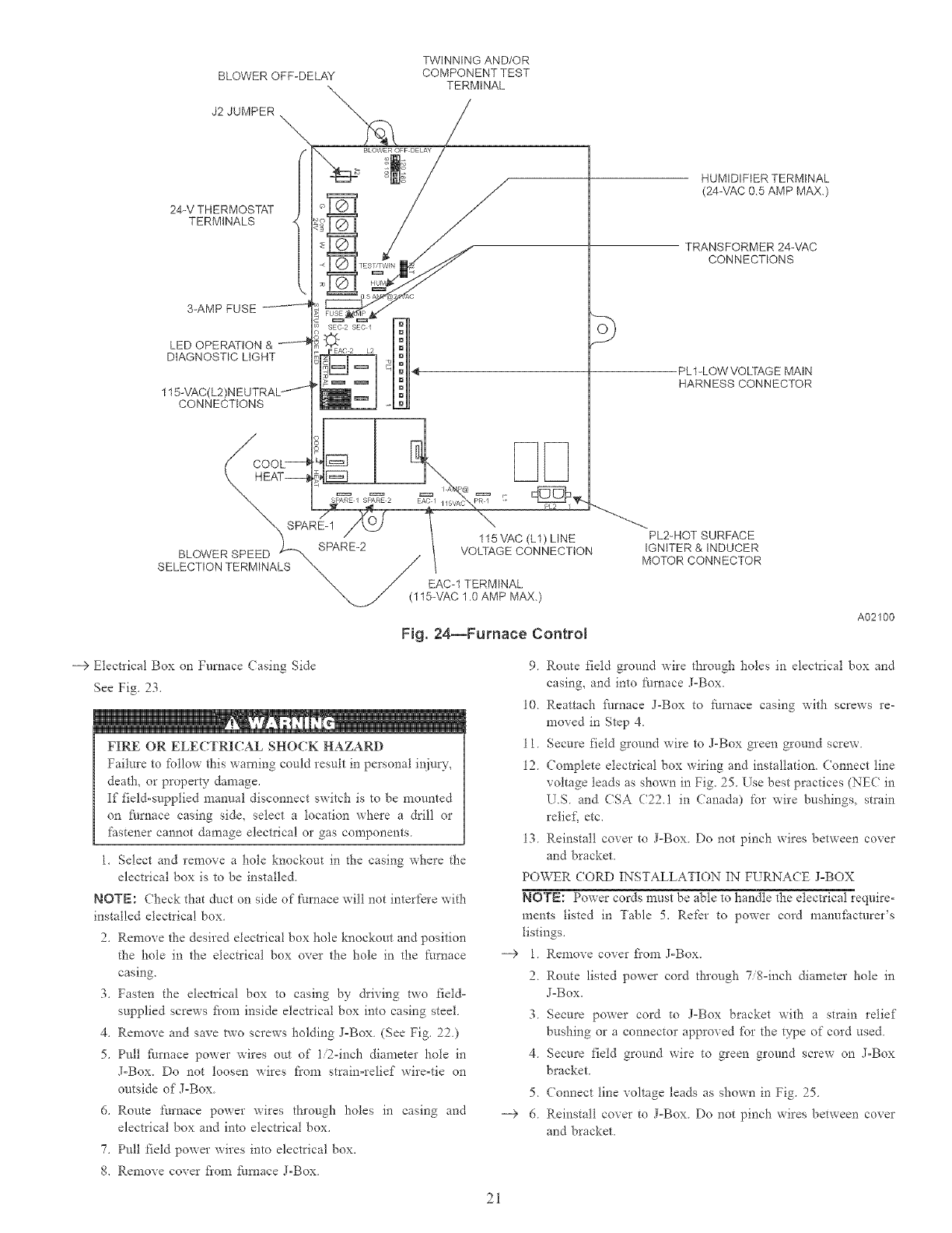
BLOWER OFF-DELAY
J2 JUMPER
TWINNING AND/OR
COMPONENT TEST
TERMINAL
24-V THERMOSTAT
TERMINALS
3-AMP FUSE
LED OPERATION &
DIAGNOSTIC LIGHT
115-VAO
CONNECTIONS
SELECTION TERMINALS
SEC 2 SEO / o}
115 VAC (L1) LINE
VOLTAGE CONNECTION
"X_! EAC-1 TERMINAL
15-VAC 1.0 AMP MAX.)
Fig. 24--Furnace Control
HUMIDIFIER TERMINAL
(24-VAC 05 AMP MAX.)
TRANSFORMER24-VAC
CONNECTIONS
PL1-LOWVOLTAGE MAIN
HARNESS CONNECTOR
PL2-HOTSURFACE
IGNITER&INDUCER
MOTOR CONNECTOR
A02100
--)Electrical Box on Furnace Casing Side
See Fig. 23,
FIRE OR ELECTRICAL SHOCK HAZARD
Failure to lk)llow this warning could result in personal injuw_
death, or property damage.
If field-supplied manual disconnect switch is to be mounted
on furnace casing side, select a location where a drill or
fastener cannot damage electrical or gas components
1. Select and remove a hole knockout in the casing where the
electrical box is to be installed
NOTE: Check that duct on side of furnace will not interfere with
installed electrical box
2. Remove the desired electrical box hole knockout and position
the hole in the electrical box over the hole in the furnace
casing.
3. Fasten the electrical box to casing by driving two field-
supplied screws fi'om inside electrical box into casing steel.
4. Remove and save two screws holding J-Box. (See Fig. 22.)
5. Pull fi_rnace power wires om of 1/2-inch diameter hole in
J-Box. Do not loosen wires from strain-relief wire-tie on
outside of J-Box.
d. Route furnace power wires through holes in casing and
electrical box and into electrical box.
7. Pull field power wires into electrical box.
8. Remove cover fiom fhrnace J-Box.
-9 1.
2_
3.
4.
5.
--+ 6.
9 Route field ground wire through holes in electrical box and
casing, and into furnace J-Box.
10 Reattach furnace J-Box to fire, ace casing with screws re-
moved in Step 4.
11. Secure field ground wire to J-Box green ground screw.
12. Complete electrical box wiring and installation. Connect line
voltage leads as shown in Fig. 25. Use best practices (NEC in
U.S. and CSA C22.1 in Canada) for wire bushings, strain
relief, etc.
13. Reinstall cover to J-Box. Do not pinch wires between cover
and bracket.
POWER (ORD INSTALLATION IN FURNACE J-BOX
NOTE: Power cords must be able to handle the electrical require-
ments listed in Table 5. Refer to power cord manufhcmrer's
listings.
Remove cover fi'om J-Box.
Route listed power cord through 7/8=inch diameter hole in
J=Box.
Secure power cord to J=Box bracket with a strain relief
bushing or a connector approved for the type of cord used.
Secure field ground wire to green ground screw on J-Box
bracket.
Connect line voltage leads as shown in Fig. 25.
Reinstall cover to J-Box. Do not pinch wires between cover
and bracket.
2i
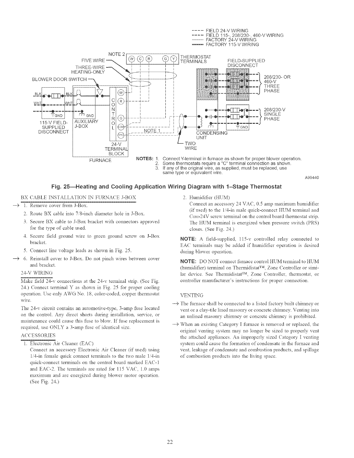
.... FIELD 24-V WIRING
.... FIELD 115-, 208/230-, 460-V WtRING
-- FACTORY 24-V WIRING
FACTORY 115-V WIRING
FIELD-SUPPLIED
DISCONNECT
115-VFIELD-
SUPPLIED
DISCONNECT
BX
--> 1,
2,
3,
AUXILIARY O
J-BOX L @
5_
--> 6.
547
TERMINA[
BLOCK
FURNACE
NOTE 1
NOTES:I. 2.
3.
CONDENSING
UNIT
?WO
WIRE
208/230-0R
460-V
THREE
PHASE
208/230-V
SINGLE
PHASE
Connect YLterminal in furnace as shown for proper blower operation.
Some thermostats require a '%" terminal connection as shown.
tf any of the original wire, as supplied, must be replaced, use
same type or equivalent wire.
Fig. 25--Heating and Cooling Application Wiring Diagram with 1-Stage Thermostat
CABLE INSTALLATION IN FURNACE J-BOX
Remove cover from J-Box.
Route BX cable into 7/8°inch diameter hole in J-Box.
Secure BX cahle to J-Box bracket with connectors approved
_br the type of cable used.
4. Secure field ground wire to green ground screw on J=Box
bracket.
Connect line voltage leads as shown in Fig. 25.
Reinstall cover to J=Box. Do not pinch wires between cover
and bracket.
24-V WIRING
Make field 24-v connections at the 24-v terminal strip. (See Fig.
24.) Connect terminal Y as shown in Fig 25 _br proper cooling
operation Use only AWG No 18, color-coded, copper thermostat
wire.
The 24-v circuit contains an automotive=type, 3-amp _ilse located
on the control Any direct shorts during installation, service, or
maintenance could cause this fuse to blow If _ime replacement is
required, use ONLY a 3-amp fuse of identical size.
ACCESSORIES
1. Electronic Air Cleaner (EAC)
Connect an accessow Electronic Air Cleaner (if used) using
1/4=in female quick connect terminals to the two male li4=in
quick-connect terminals on the control board marked EAC-1
and EAC-2 The temlinals are rated for 115 VAC, 1.0 amps
nlaxinmm and are energized during blower motor operation
(See Fig 24.)
A99440
2. Humidifier (HI_M)
Connect an accessm7 24 VAC, 05 amp maxin-mm humidifier
(if used) to the 1/4=in male quick-connect HUM terminal and
Co_>24V screw terminal on the contlol board thermostat strip.
The HUM terminal is energized when pressure switch (PRS)
closes (See Fig. 24)
NOTE: A field-supplied, l I5-v controlled relay connected to
EAC terminals may be added if humidifier operation is desired
during blower operation
NOTE: DO NOT connect furnace control HUM tem_inal to HUM
(humidifier) terminal on ThermidistaF_L Zone Controller or simi-
lar device. See Thern_idistat TM, Zone Controller, thermostat, or
controller manuRtcmrer's instl_actions _br proper connection.
-->
-->
VENTING
The fi/rnace shall be connected to a listed facto1T built chimney or
vent or a clay-tile lined masonw or concrete chimney Venting into
an unlined masonry chinmey or concrete chinmey is prohibited
When an existing Category I furnace is removed or replaced, the
original venting system may no longer be sized to properly vent
the attached appliances. An improperly sized Category I venting
system could cause the formation of condensate in the furnace and
vent, leakage of condensate and combustion products, and spillage
of combustion products into the living space.
22
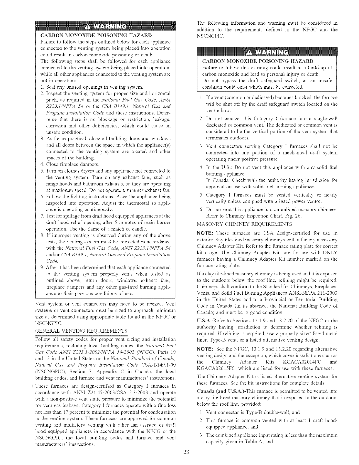
CARBON MONOXIDE POISONING HAZARD
Failure to follow the steps outlined below for each appliance
connected to the venting system being placed into operation
could result in carbon monoxide poisoning or death.
The following steps shall be followed for each appliance
connected to the venting system being placed into operation,
while all other appliances connected to the venting system are
not in operation:
1. Seal any unused openings in venting system,
2 Inspect dae venting system for proper size and horizontal
pitch, as required in the A'ational Fuel Gas Cod< AA'SS
Z223.1JiV_7<I 54 or the C%14 B149.1, A_t_n'al Gas and
Propane Dv.stcd/atinn ('()de and these instructions. Deter-
mine that there is no blockage or restrictiom leakage,
cmTosion and other deficiencies, which could cause an
unsafe condition.
3. As far as practical, close all building doors and windows
and all doors between the space in which the appliance(s)
connected to the venting system are located and other
spaces of the building.
4. Close fireplace dampers.
5. Turn on clothes dryers and any appliance not connected to
the venting system. Turn on any exhaust fires, such as
range hoods and bathroom exhausts, so they are operating
at maximum speed. Do not operate a summer exhaust tim.
6. Follow d_e lighting instructions. Place the appliance being
inspected into operation. Adjust the them_ostat so appli:
ance is operating continuously.
7. Test for spillage fiom &ak hood equipped appliances at the
draft hood relief opening after 5 minutes of main burner
operation. Use the flame of a match or candle.
8. If improper venting is observed during any of the above
tests, the venting system must be cot_'ected in accordance
with the Yc_tiona[ Fne[ Gas ('ode, A:V._7 Z223.1<\_1 54
andor CSt B149.1, :\'_:mra[ Gas and Propane Is_sta[iat/on
('()de.
9 Aker it has been determined tl'mt each appliance connected
to the venting system properly vents when tested as
outlined above, remm doors, windows, exhaust £ims,
fireplace dampers and any other gas-fired burning appli:
ance to their previous conditions of use
Vent system or vent connectors may need to be resized Vent
systems or vent connectors must be sized to approach minimum
size as determined using appropriate table found in the NFGC or
NS(NGPI(.
GENERAL VENTING REQUIREMENTS
Follow all safety codes for proper vent sizing and installation
requirements, including local building codes, the A'ationa/F_le[
Gas Code A_\L%7Z223.I-2002AVFPA 54-2002 (_VFGO, Pags 10
and 13 in the United States or the Y(_tinna[ Sl_md(_rd of Canada,
:\'_mr_U Gas and Propane ]nslaliafion ('ode CSA-BI49.1:00
(NSCNGPI(), Section 7, Appendix C in Canada, the local
building codes, and fl/mace and vent manufacturers' instructions.
i_> These Nmaces are design:certified as Category I Nmaces in
accordance with ANSI Z21.47:2003iCSA 2.3:2003 and operate
with a non:positive vent static pressure to minimize the potential
for vent gas leakage. Category I Nmaces operate with a flue toss
not less than 17 percent to minimize the potential for condensation
in the venting system. These Nrnaces are approved for common
venting and multistory venting with other fire assisted or &aft
hood equipped appliances in accordance with the NFCG or the
NSCNGPIC, the local building codes and Nmace and vent
manufacturers' instructions.
23
The %llowing in%rotation and warning must be considered in
addition to the requirements defined in the NFG( and the
NSCNGPI(
_, 1
CARBON MONOXIDE POISONING HAZARD
Failure to follow this warning could result in a build:up of
carbon monoxide and 1cad to personal injuW or death
Do not bypass the &afi safeguard switch, as an unsaf_
condition could exist which must be corrected.
1 Ifa vent (common or dedicated) becomes blocked, the fimmce
will be shut off by the draft safeguard switch located on the
vent elbow.
2Do not connect this Category I furnace into a single-wall
dedicated or common vent. The dedicated or commma vent is
considered to be the vertical portion of the vent system that
terminates outdoors.
3 Vent connectors serving (ategow- I furnaces shall not be
connected into any portion of a mechanical draft system
operating under positive pressure.
4 In the US: Do not vent this appliance with any solid fuel
burning appliance
In Canada: Check with the authority having jurisdiction for
approval on use with solid fhel bml_ing appliance.
5 Category I furnaces must be vented vertically or nearly
vertically unless equipped with a listed power ventor.
6 Do not vent this appliance into an unlined masonry chimney.
Refkr to (hirnney Inspectima (hart, Fig. 26
MASONRY CHIMNEY REQUIREMENTS
NOTE: These fl_rnaces are <SA design:certified for use in
exterior clay tile:lined masonry chimneys with a factoo accessory
(himney Adapter Kit Refer to the furnace rating plate for correct
kit usage The Chimney Adapter Kits are for use with ONLY
fimmces having a (himney Adapter Kit number marked on the
furnace rating plate.
Ifa clay tile:tined masonry chimney is being used and it is exposed
to the outdoors below the roof line, relining might be required.
Chimneys shall conform to the Standard for Chimneys, Fireplaces..
Vents, and Soild Fuel Burning Appliances ANSI NFPA 2! 1:2003
in the United States and to a Provincial or Territorial Building
(7ode in Canada (in its absence, the National Building (7ode of
Canada) and must be in good condition.
U.S.A.:Refer to Sections 13.1.9 and 13.2.20 of the NFGC or the
authority having jurisdiction to detem_ine whether relining is
required. If relining is required, use a properly sized listed metal
liner, Type-B vent, or a listed alternative venting design.
NOTI=: See the NFG(, 13.1.9 and 13.2.20 regarding alternative
venting design and the exception, which cover installations such as
the Chimney Adapter Kits KGACA02014FC and
KGA( A02015FC, which are listed for use with these furnaces
The Chimney Adapter Kit is listed alternative venting system for
these fllmaces. See the kit instl_ctions [br complete details.
Canada (and U.S.A°):This :gtrcmce is permitted to be vented into
a clay file:lined masonry chimney that is exposed to the outdoors
below the roof line, prm'ided:
1. Vent connector is Type:B double:wall, and
2. This furnace is common vented with at least 1 draft hood:
equipped appliance, and
3. The combined appliance input rating is less than the maximum
capacity- given in Table A, and
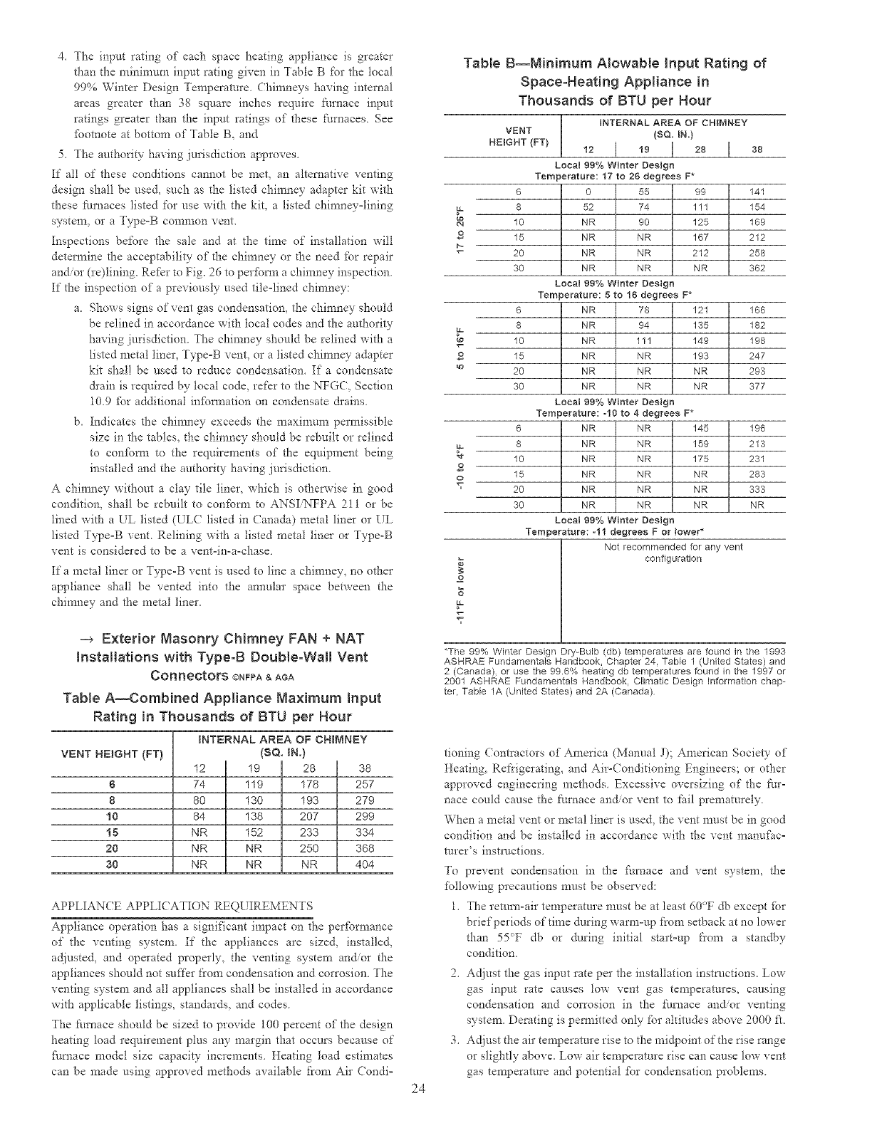
4. Theinputratingof eachspaceheatingapplianceisgreater
thantheminimun_inputratinggiveninTableBforthelocal
99%WinterDesignTemperature. Chimneys having internal
areas greater than 38 square inches require t\trnace input
ratings greater d'mn the input ratings of these furnaces. See
fbotnote at bottom of Table B, and
5. The authority having jurisdiction approves.
If all of these conditions cannot be met, an alternative venting
design shall be used, such as the listed chimney adapter kit with
these furnaces listed for use with the kit, a listed chimney=lining
system, or a Type=B common vent.
Inspections before the sale and at the time of installation will
detellr_ine the acceptability of the chimney or d-_e need for repair
and/or (re)lining. Refur to Fig. 26 to perfbrm a chimney inspection.
If the inspection of a previously used tile=lined chimney:
a. Shows signs of vent gas condensation, the chimney should
be relined in accordance with local codes and the authori V
having jurisdiction. The chimney should be relined with a
listed metal liner, Type-B vent, or a listed chimney adapter
kit shall be used to reduce condensation. If a condensate
&ain is required by local code, refer to the NFGC, Section
10.9 fbr additional infbm_ation on condensate &ains.
b. Indicates the chinmey exceeds the maxinmm permissible
size in the tables, the chimney should be rebuilt or relined
to con:_bm_ to the requirements of the equipment being
installed and the authority having jurisdiction.
A chimney without a clay tile liner, which is othepwise in good
condition, shall be rebuilt to confom? to ANSIiNFPA 211 or be
lined with a UL listed (ULC listed in Canada) metal liner or UL
listed Type=B vent. Relining with a listed metal liner or Type-B
vent is considered to be a vent-in=a=chase.
If a metal liner or Type-B vent is used to line a chinmey, no other
appliance shall be vented into the annular space between the
chimney and the metal liner.
-_ Exterior Masonry Chimney FAN + NAT
Installations with Type-B DouNe-WaH Vent
Connectors ©NFPA & AGA
TaRe A--Combined Appliance Naximum Input
Rating in Thousands of BTU per Hour
INT_CRNAL AREA OF CHMNEY
VENT HEIGHT (FT) ($Q. IN.)
8
8
10
15
20
30
38
74 119 178 257
80 130 193 279
84 138 207 299
NR 152 233 334
NR NR 250 368
NR NR NR 404
APPLIANCE APPLI(ATION REQ[ IREMENTS
Appliance operation has a significant impact on the per%finance
of the venting system. If the appliances are sized, installed,
adjusted, and operated properly, the venting system and/or the
appliances should not suffer from condensation and corrosion. The
venting system and all appliances shall be installed in accordance
with applicable listings, standards, and codes.
The furnace should be sized to provide 100 percent of the design
heating load requirement plus any margin that occurs because of
Nnmce model size capacity increments. Heating load estimates
can be made using approved methods available ti'om Air Condi=
£
ta=
ta.
£
Table B--Ninimum Alowable input Rating of
Space-Heating ApNiance in
Thousands of BTU per Hour
iiNTERNAL AREA OF CHIMNEY
VENT (SQ. IN.)
NEIGNT(FT)12 [ 19 I 28 I a8
Local 99% Winter Design
Temperature: 17 to 26 degrees F*
6 0 55 99 141
8 52 74 111 154
10 NR 90 125 169
15 NR NR 167 212
20 NR NR 212 258
30 NR NR NR 362
Loea199%Winter Design
Temperature: 5 to 19 degrees F*
6 NR 78 121 166
8 NR 94 135 182
10 NR 111 149 198
15 NR NR 193 247
20 NR NR NR 293
30 NR NR NR 377
Loealgg%winter Design
Temperature:-10 to 4 degrees F*
6 NR NR 145 196
8 NR NR 159 213
10 NR NR 175 231
15 NR NR NR 283
20 NR NR NR 333
30 NR NR NR NR
Local 99% Winter Design
Temperature: -11 degrees F or lower*
Not recommended for any vent
configuration
*The 99% Winter Design Dry-Bulb (db) temperatures are found in the 1993
ASHRAE Fundamentals Handbook, Chapter 24, Tabte 1 (United States) and
2 (Canada), or use the 99.6% heating db temperatures found in the 1997 or
2001 AEHRAE Fundamentals Handbook, Climatic Design information chap-
ter, Table 1A (United States) and 2A (Canada)
24
tioning (ontractors of America (Manual J); American Society of
Heating, Refrigerating, and Air-(onditioning Engineers; or other
approved engineering methods. Excessive oversizing of the fur=
nace could cause the fmTmce and/or vent to fail prematurely.
When a metal vent or metal liner is used, the vent must be in good
condition and be installed in accordance with the vent manufac=
turer's instructions.
To prevent condensation in the fimaace and vent system, the
following precautions must be observed:
1. The return=air temperature must be at least 60°F db except [br
brief periods of time during warn>up from setback at no lower
than 55_F db or during initial start=up from a standby
condition.
2. Adjust the gas input rate per the installation instructions. Low
gas input rate causes tow vent gas temperatures, causing
condensation and corrosion in the ihmace an_or venting
system. Derating is pem_itted only for altitudes above 2000 ft.
3. Adjust the air temperature rise to the midpoint of the rise range
or slightly above. Low air temperature rise can cause low vent
gas temperature and potential _br condensation problems.
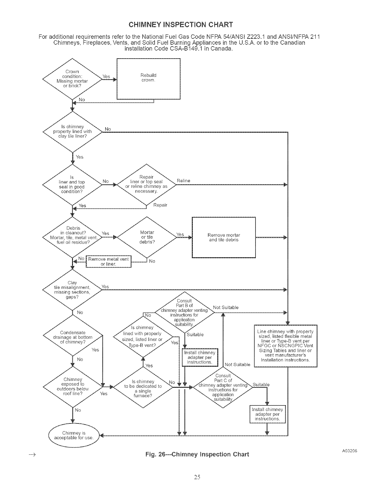
CHIMNEY iNSPECTiON CHART
For additional requirements refer to the National Fuel Gas Code NFPA 54/ANSI Z223.1 and ANSI/NFPA 211
Chimneys, Fireplaces, Vents, and Solid Fuel Burning Appliances in the U.S.A. or to the Canadian
installation Code CSA-B149.1 in Canada.
Crown
condition: Rebuild
Missing mortar crown
or brick?
Is chimney No
<_,_ _:_ePrOperty lined with
liner?
is Repair
liner and top liner or top seat
seal in good or reline chimney as
condition? necessary.
Yes Repair
Reline
Debris
in cleanout? Mortar
Mortar, tile, metal venL or tile Remove mortar
fuel oil residue? debris? and tile debris
Remove metal vent
or liner.
-->
Clay
tile misalignment,
missing sections_
gaps?
No
Condensate
drainage at bottom
No
Chimney
exposed to
outdoors below
roof line?
Chimney is
acceptable for use.
Yes
chimney
lined with properly
sized_ listed liner or
vent?
Part B of
instructions for
application
;uitable
Not Suitable
Install chimney
adapter per
instructions.
Yes 4ot Suitable
Line chimney with property
sized, listed flexible metal
liner or Type-B vent per
NFGC or NSCNGPIC Vent
Sizing Tables and liner or
vent manufacturer's
Installation instructions.
Is chimney
to be dedicated to
a single
furnace?
Part C of
instructions for
application
>,Suitable
Install chimney
adapter per
instructions.
Fig. 26--CMmney Inspection Chart A03206
25
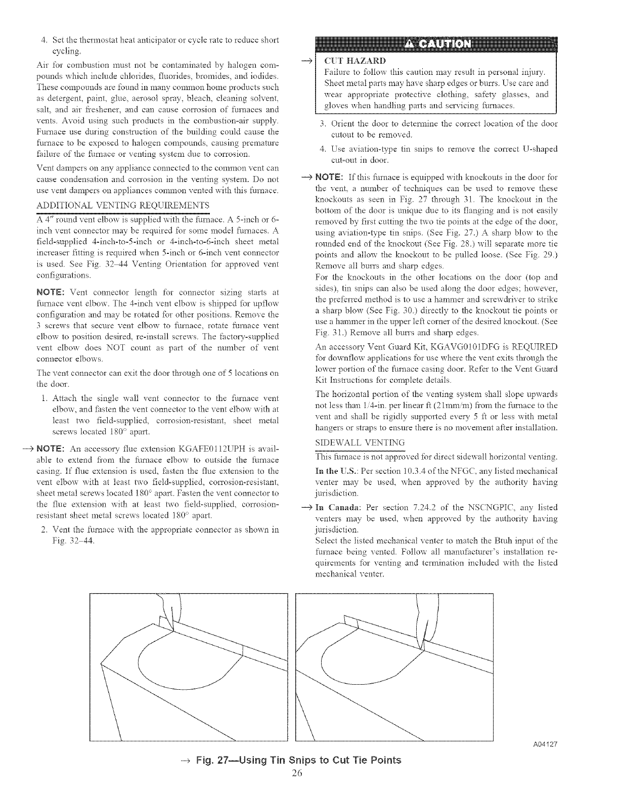
4. Set the thermostat heat anticipator or cycle rate to reduce short
cycling.
Air for confbustion must not be contaminated by halogen como
pounds which include chlorides, fluorides, bromides, and iodides
These compounds are found in many common home products such
as detergent, paint, glue, aerosol spray, bleach, cleaning solvent,
salt, and air /ieshener, and can cause corrosion of furnaces and
vents. Avoid using such prodtlcts in the cornbustion=air supply.
Furnace use during construction of the building could cause the
ihmace to be exposed to halogen compounds, causing premature
ihilure of the furnace or venting system dtle to corrosion.
Vent dampers on any appliance connected to the common vent can
cause condensation and con'osion in the venting system. Do not
use vent dampers on appliances common vented with this Nrnace.
ADDITIONAL VENTING REQUIREMENTS
A 4" round vent elbow is supplied with the Nmace. A 5-inch or 6o
inch vent connector may be required %r some model Nmaces. A
field=supplied 4-inch-to-5-inch or 4=inch=to=6-inch sheet metal
increaser fitting is required when 5-inch or 6oinch vent connector
is used. See Fig. 32 44 Venting Orientation ibr approved vent
configurations.
NOTE: Vent connector length for connector sizing starts at
Nmace vent elbow. The 4oinch vent elbow is shipped ibr upflow
configuration and may be rotated ibr other positions. Remove the
3 screws that secure vent elbow to fhmace, rotate [hrnace vent
elbow to position desired, re-install screws. The factov-supplied
vent elbow does NOT count as part of the number of vent
connector elbows.
The vent connector can exit the door through one of 5 locations on
the door.
1. Attach the single walt vent connector to the fi/mace vent
elbow, and ihsten the vent connector to the vent elbow with at
least two fieldosupplied, corrosion-resistant, sheet metal
screws located 180 ° apart.
--> NOTE: An accessory flue extension KGAFE0112UPH is avail°
able to extend fiom the farnace elbow to outside the furnace
casing. If flue extension is used, _sten the flue extension to the
vent elbow with at least two field-supplied, corrosion-resistant,
sheet metal screws located 180 _>apart. Fasten the vent connector to
the flue extension with at least two field-supplied, con'osiono
resistant sheet metal screws located 180 ° apart.
2. Vent the furnace with the appropriate connector as shown in
Fig. 32 44.
--> (IT HAZARD
Failure to %11ow this caution may result in personal injury.
Sheet metal parts may have sharp edges or bun's Use care and
wear appropriate protective clothing, safety glasses, and
gloves when handling parts and servicing _/rnaces.
3. Orient the door to determine the correct location of the door
cutout to be removed
4. Use aviation-type tin snips to remove the correct U-shaped
cut-out in door.
--> NOTE: If this l_maace is equipped with knockouts in the door %r
the vent, a nmnber of techniques can be used to remove these
knockouts as seen in Fig. 27 through 31. The knockout in the
bottom of the door is unique due to its flanging and is not easily
removed by first cutting the two tie points at the edge of the door,
using aviation-type tin snips. (See Fig. 27.) A sharp blow to the
rounded end of the knockout (See Fig. 28.) will separate more tie
points and allow the knockout to be pulled loose. (See Fig. 29.)
Remove all burrs and sharp edges.
For the knockouts in the other locations on the door (top and
sides), tin snips can also be used along the door edges; however,
the preferred method is to use a hammer and screwdriver to strike
a sharp blow (See Fig. 30.) directly to the knockout tie points or
use a hammer in the upper left corner of the desired knockout. (See
Fig. 31.) Remove all bun's and sharp edges.
An accessoO' Vent Guard Kit, KGAVG0101DFG is REQUIRED
for downflow applications for use where the vent exits through the
lower portion of the It/mace casing door. Refer to the Vent Guard
Kit Instructions for complete details.
The horizontal portion of the venting system shall slope upwards
not less than li4oin, per linear ft (2 hum/m) fiom the fhrnace to the
vent and shall be rigidly supported every 5 ft or less with metal
hangers or straps to ensure there is no movement after installation.
SIDEWALL VENTING
This Nrnace is not approved for direct sidewall horizontal venting.
In the U.S.: Per section 10.3.4 of the NFGC, any listed mechanical
renter may be used, when approved by the authori V having
jurisdiction.
--> In Canada: Per section 7242 of the NSCNGPIC, any listed
renters may be used, when approved by the authority having
jurisdiction.
Select the listed mechanical renter to match the Bmh input of the
lhrnace being vented. Follow all manu_hcturer's installation re-
quirements for venting and termination included with the listed
mechanical renter.
-_ Fig, 27--Using Tin Snips to Cut Tie Points
26
A04127
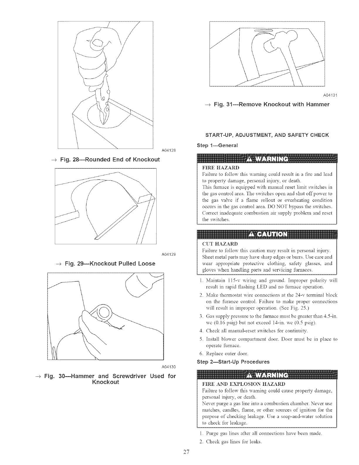
-_ Fig, 28--Rounded End of Knockout
A04128
A04129
-_ Fig. 29--Knockout Pulled Loose
A04130
-+ Fig. 30--Hammer and Screwdriver Used for
Knockout
27
A04131
-_ Fig. 31--Remove Knockout with Hammer
START-UP, ADJUSTMENT, AND SAFETY CHECK
Step l--General
FIRE HAZARD
Failure to follow this warning could result in a fire and lead
to property damage, personal injury, or death
This _k/rnace is equipped with manual reset limit switches in
t!_e gas control area The switches open and shut offpower to
the gas valve if a flame rollout or overheating condition
occurs in the gas control area. DO NOT bypass the switches.
Con'ect inadequate combustion air supply problem and reset
the switches.
(:IT HAZARD
Failure to %llow d_is caution may result in personal ir_jury.
Sheet metal parts may have sharp edges or burrs Use care and
wear appropriate protective clothing, safety glasses, and
gloves when handling parts and sela'icing _/maces.
1 Maintain 115-v wiring and ground Improper polarity will
result in rapid flashing LED and no [_urnace operation.
2Make them_ostat wire connections at d'_e 24-v terminal block
on the furance control. Failure to make proper connections
will result in improper operation (See Fig. 25.)
3 Gas supply pressure to the furnace must be greater than 4.5-in.
wc (016 psig) but not exceed 14-in wc (05 psig)
4 (beck all manual-reset switches fbr continuity
5 Install blower compartment door. Door must be in place to
operate fnrnace
6. Replace outer door.
Step 2--Start-Up Procedures
FIRE AND EXPLOSION HAZARD
Failure to fbllow this warning could cause property damage,
personal injm 7, or death.
Never purge a gas line into a combustion chamber. Never use
matches, candles, flame, or other sources of ignition _br the
purpose of checking leakage Use a soap-and=water solution
to check for leakage.
1 Purge gas lines after all connections have been made
2(beck gas lines for leaks
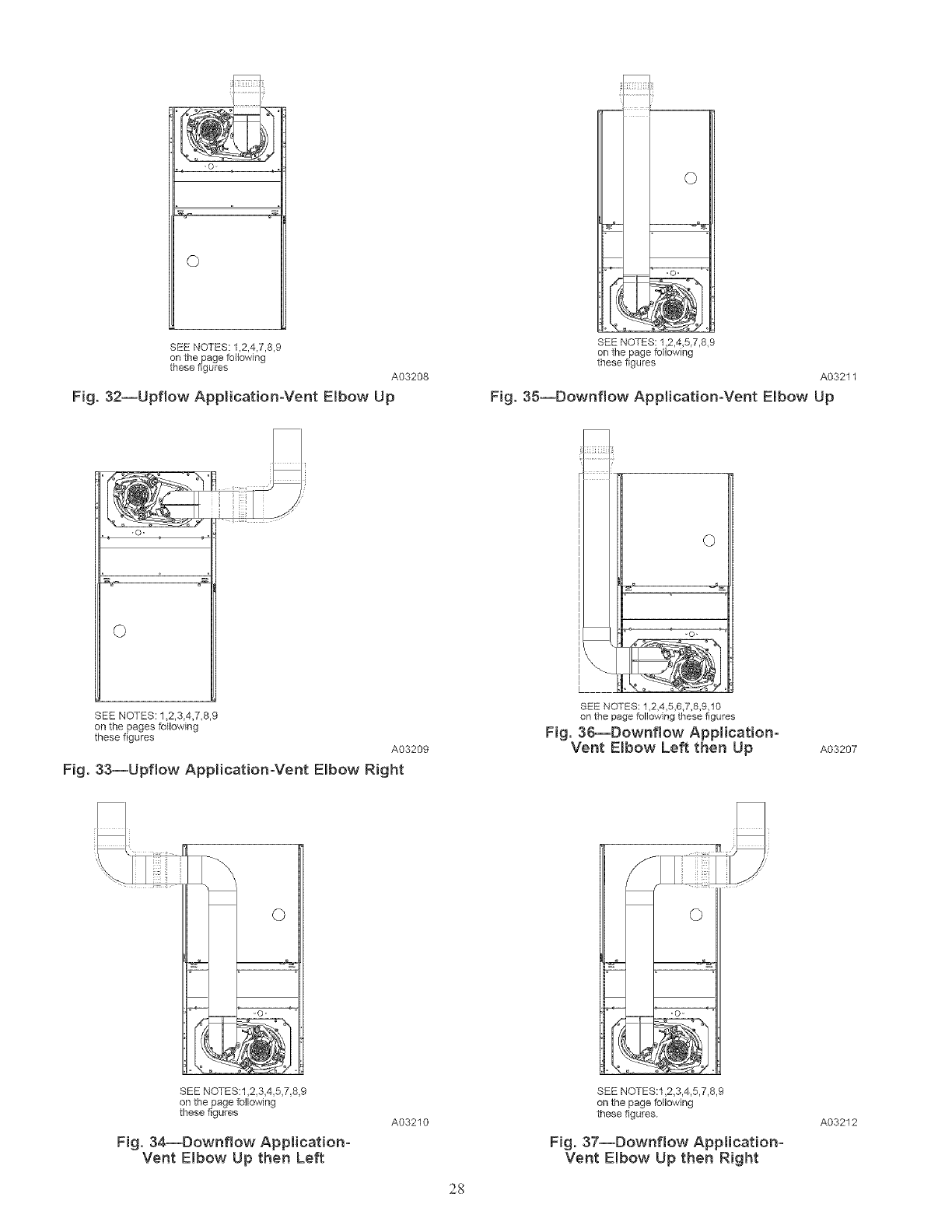
©
SEE NOTES: 1,2,4,7,8,9
on the page following
these figures A03208
Fig. 32--Upflow Application-Vent Elbow Up
SEE NOTES: 1,2,4,5,7,8,9
on the page following
these figures
A03211
Fig. 35--Downflow Application-Vent Elbow Up
©
SEE NOTES: 1_2,3,4,7,8,9
on the pages following
these figures
A03209
Fig. 33--Upflow Application-Vent Elbow Right
SEE NOTES: 1,2,4,5,6,7,8,9,10
on the page following these figures
Fig. 36--Downflow Application-
Vent Elbow Left then Up A03207
SEE NOTES:1,2,3 4,5,7,8,9
on the page following
these figures
Fig. 34--Downflow Application-
Vent Elbow Up then Left
A03210
2S
SEE NOTES:l,2,3,4,5,7,8,9
on the page following
these figures
Fig. 37--Downflow Application-
Vent Elbow Up then Right
A03212
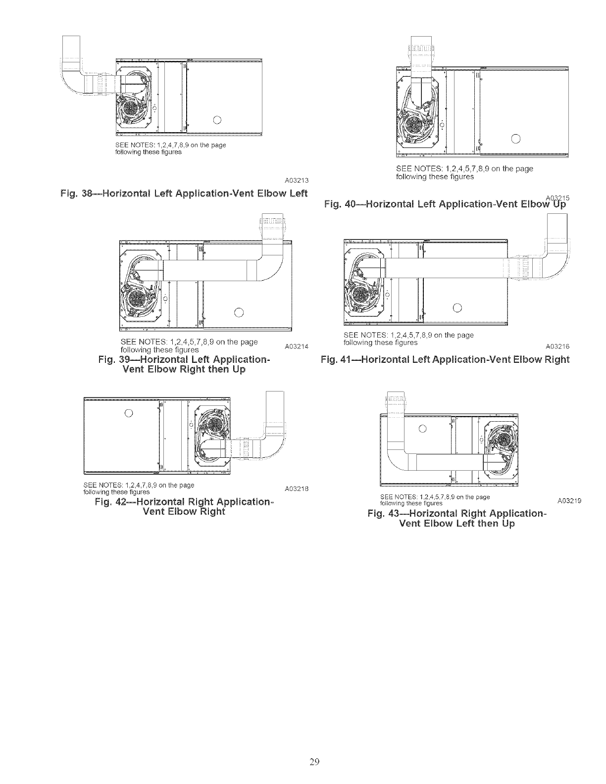
©
SEE NOTES: 1,2_4,7,8,9 on the page
following these figures
A03213
Fig. 38--Horizontal Left Application-Vent Elbow Left
SEE NOTES: 1,2,4,5,7,8,9 on the page
following these figures
Fig. 40--Horizontal Left Application-Vent EJbov_°_2_5
I01
SEE NOTES: 1,2,4,5,7,8,9 on the page
following these figures
Fig. 39--Horizontal Left Application-
Vent Elbow Right then Up
SEE NOTES: 1,2,4,7,8,9 on the page
following these figures
Fig. 42--Horizonta! Right Application-
Vent Elbow Right
A03214
A03218
SEE NOTES: 1,2,4,5,7,8,9 on the page
following these figures A03216
Fig. 41--Horizontal Left Application-Vent Elbow Right
SEE NOTES: 1 2,4,5,7,8 9 on the page
following these figures
Fig. 43--Horizontal Right Application-
Vent Elbow Left then Up
A03219
29
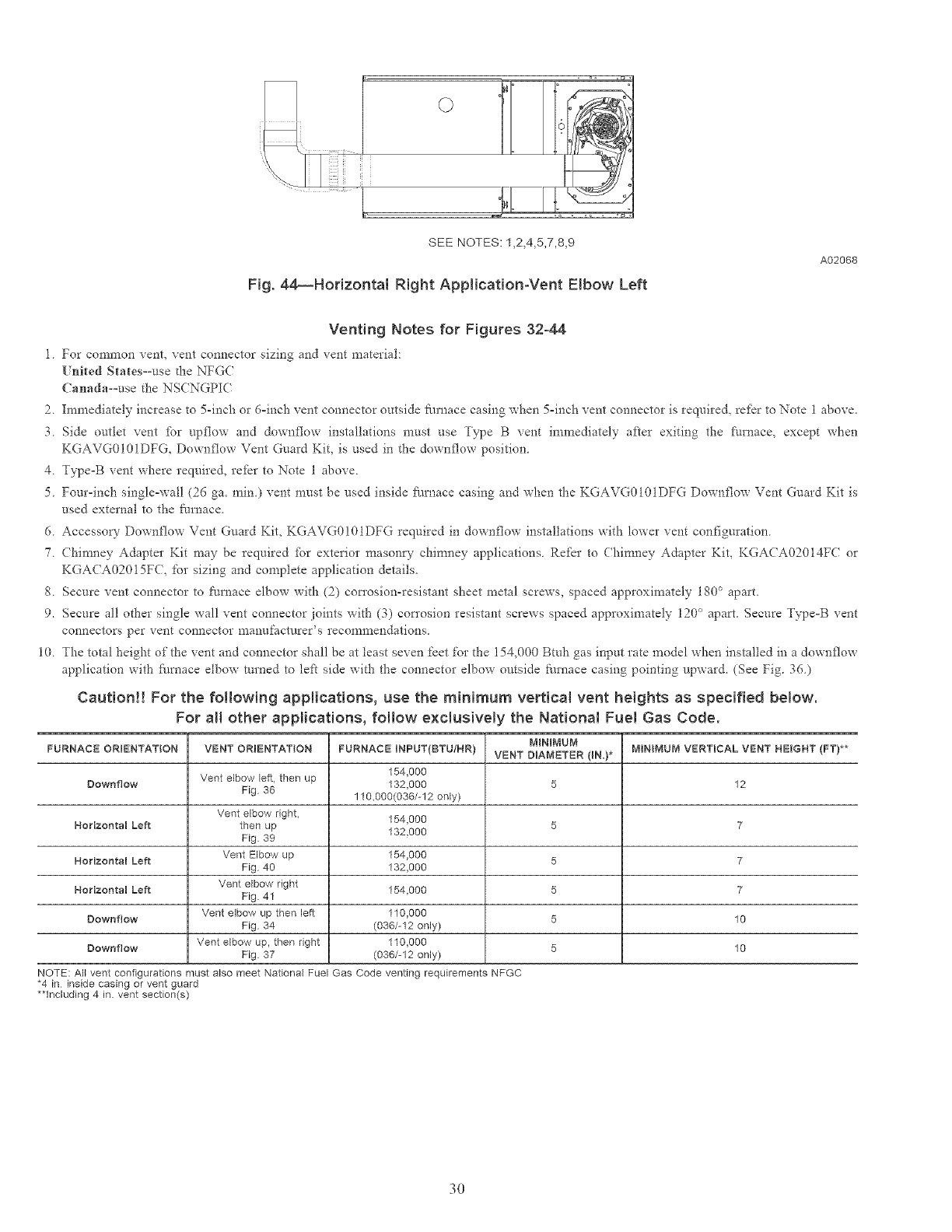
i
SEE NOTES: 1,2,4,5,7,8,9
Fig. 44_Horizontal Right ApNication-Vent Elbow Left
A02068
Venting Notes for Figures 32-44
1 For common vent, vent connector sizing and vent material:
[ hired SIates==use d_e NFGC
Canada=use the NSCNGPIC
2 Immediately increase to 5-inch or d=inch vent connector outside Parnace casing when 5=inch vent connector is required, refer to Note 1 above.
3 Side outtet vent for upflow and downflow installations must use Type B vent immediately after exiting the furnace, except when
KGAVG0101DFG, Downflow Vent Guard Kit, is used in the downflow position
4 Type=B vent where required, refer to Note 1 above
5 Four-inch single=wall (26 ga. rain) vent must be used inside _/rnace casing and when the KGAVG0101DFG Downftow Vent Guard Kit is
used external to the furnace
6 Accesso W Downt'low Vent Guard Kit, KGAVG0!01DFG required in downflow installations wit}*lower vent configuration
7 (hinmey Adapter Kit may be required [br exterior mason W chinmey applications Re*_r to Chimney Adapter Kit, KGACA02014FC or
KGA(A02015FC, for sizing and complete application details.
8 Secure vent connector to furnace elbow with (2) cm_'osion-resistant sheet metal screws, spaced approximately 1%° apart.
9. Secure al! other single wal! vent connector joints with (3) corrosion resistant screws spaced approximately 120° apart. Secure Type=B ",gent
connectors per vent connector manufacturers recommendations.
10. The total height of the vent and connector shall be at least seven feet for the 154,000 Btuh gas input rate model when installed in a downflow
application with Nmace elbow turned to left side with the connector elbow outside Nmace casing pointing upward. (See Fig. 36.)
Caution!! For the following applications, use the minimum vertieat vent heights as specified be{ow.
For aH other applications, follow exclusivemy the National Fuel Gas Code.
MINIMUM
FURNACE ORIENTAT{ON VENT ORIENTATION FURNACE INPUT(BTU/NR / VENT DIAMETER (IN.}* MININUM VERTICAL VENT HEIGHT (FT/**
Downflow Vent elbow left then up 154,000
132,000 5 12
Fig 36 110,000(036/-12 only)
Vent elbow right, 154,000 5 7
Horizontal Left then up 132,000
Fig 39
Herizontal Left Vent Elbow up 154,000 5 7
Fig 40 132,000
Horizontal Left Vent elbow right 154,000 5 7
Fig 41
Downflow Vent elbow up then left 110,000 5 10
Fig 34 (036/-12 only)
Downflew Vent elbow up, then right 110,000 5 10
Fig 37 (036/-12 only)
NOTE: All vent configurations must also meet National Fuel Gas Code venting requirements NFGC
*4 in inside casing or vent guard
**Including 4 in. vent section(s)
30
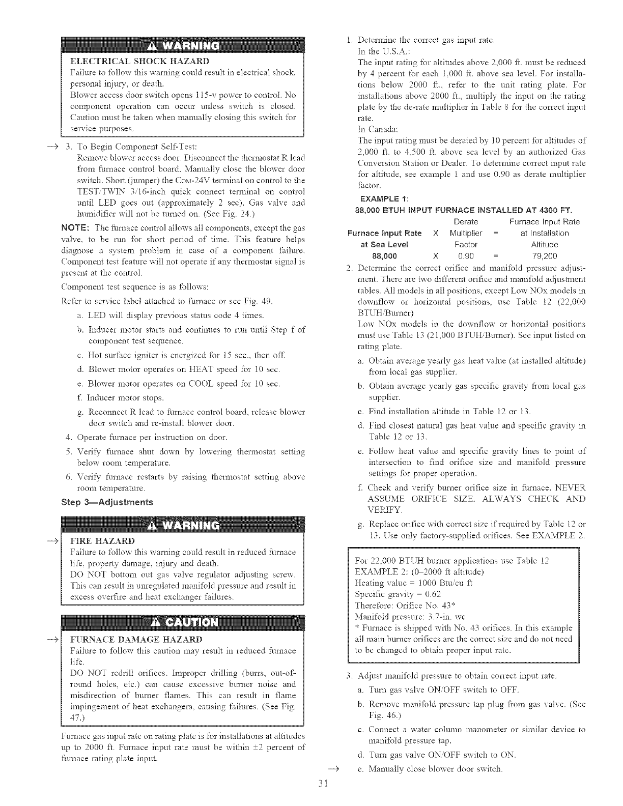
____>
____>
ELECTRICAL SHOCK HAZARD
Failure to %llow this warning could result in electrical shock,
personal irtjury, or death
Blower access door switch opens 115-v power to control. No
component operation can occur unless switch is closed
Caution must be taken when manually closing this switch for
service purposes.
3, To Begin Component Self=Test:
Remove blower access door, Disconnect the d_em_ostat R lead
f'om furnace conhol boaid, Manually close the blower door
switch. Short (lumper) the (ox_=24V terminal on control to the
TEST/TWIN 3/16-inch quick connect terminal on control
until LED goes out (approximately 2sec). Gas valve and
humidifier will not be turned on. (See Fig. 24.)
NOTE: The fiul_ace control allows all components, except the gas
valve, to be run for short period of time. This fkature helps
diagnose a system problem in case of a component fifilure.
Component test feature will not operate if any thermostat signal is
present at the control.
Component test sequence is as %llows:
Refer to service label attached to Nmace or see Fig. 49.
a. LED will display previous status code 4 times.
b. Inducer motor starts and continues to run until Step f of
component test sequence.
c. Hot surface igniter is energized %r 15 sec., then off,
d. Blower motor operates on HEAT speed for 10 sec.
e. Blower motor operates on (OOL speed for 10 sec.
£ Inducer motor stops.
g. Reconnect R lead to t'umace control board, release blower
door switch and re-install blower door.
4. Operate Nmace per instruction on door.
5. Verii) Nmace shut down by lowering thermostat setting
below room temperature.
6. Verii)- furnace restarts by raising thermostat setting above
roon'l temperature
Step 3--Ad}ustments
FIRE HAZARD
Failure to %llow this warning could result in reduced I_urnace
tifc, property damage, injury and death.
DO NOT bottom out gas valve regulator a_iiusting screw
This can result in unregulated mani%ld pressure and result in
excess overfire and heat exchanger failures
F[ RNACE DAMAGE HAZARD
Failure to %llow this caution may result in reduced furnace
tifc
DO NOT re&ill orifces Improper &illing (burrs, out-of=
round holes, etc.) can cause excessive burner noise and
misdirection of burner flames. This can result in flame
impingement of heat exchangers, causing failures. (See Fig.
47.)
Furnace gas input rate on rating plate is %r installations at ahimdes
up to 2000 ft Furnace input rate must be within +2 percent of
furnace rating plate input. ___>
31
1 Determine the con'ect gas input rate.
In the l_ .S.A :
The input rating t'or ahimdes above 2,000 fL must be reduced
by 4 percent fbr each 1,000 it. above sea level. For installa-
tions below 2000 it, refer to the unit rating plate. For
installations above 2000 ft. multiply the input on the rating
plate by the de-rate muhiplier in Table 8 for the con'ect input
rate
In Canada:
The input rating nmst be derated by 10 percent t'or ahimdes of
2,000 it. to 4,500 fL above sea level by an authorized Gas
( onversion Station or Dealer. To determine correct input rate
%r altitude, see example 1 and use 0.90 as derate multiplier
fSctor
EXAMPLE 1:
88,000 BTUH INPUT FURNACE BNSTALL_=D AT 4300 FT.
Derate Furnace Input Rate
Furnace Input Rate X Multiplier at Installation
at Sea Leve_ Factor Altitude
88,000 X 0.90 79,200
2 Detenrline the correct orifice and manifold pressure adjust-
mont. There are two different orifice and manifbld adjustment
tables. All models in all positions, except Low NOx models in
downflow or horizontal positions, use Table 12 (22,000
BTUHiBumer)
Low NOx models in the downflow or horizontal positions
must use Table 13 (21,000 BTUHiBumer). See input listed on
rating plate.
a. Obtain average yearly gas heat value (at installed altitude)
fl'om local gas supplier.
b. Obtain average yearly gas specific gravity fi'om local gas
supplier.
c. Find installation altitude in Table 12 or 13.
d. Find closest natural gas heat value and specific gravity in
Table 12 or 13.
e. Follow heat value and specific gravity lines to point of
intersection to find orifice size and manifbld pressure
settings %r proper operation.
£ (hock and verif) burner orifice size in %mace. NEVER
ASSUME ORIFI(E SIZE. ALWAYS (HECK AND
VERIFY.
g. Replace orifice with correct size if required by Table 12 or
13. Use only fhctory=supplied orifices. See EXAMPLE 2.
For 22,000 BTUH burner applications use Table 12
EXAMPLE 2:(0 2000 ft ahimde)
Heating value 1000 Btuicu ft
Specific gravity 0.62
Therefore: Orifce No. 43*
Manifold pressure: 3.7-in. we
* Furnace is shipped with No. 43 orifices. In this example
all main burner orifices are the correct size and do not need
to be changed to obtain proper input rate.
Adjust mani%ld pressure to obtain correct input rate
a Turn gas valve ON/OFF switch to OFF
b Remove mani%ld pressure tap plug f'om gas valve, (See
Fig. 46)
c (onnect a water column manometer or similar device to
manifbld pressure tap.
d Tufa gas valve ON/OFF switch to ON.
e Manually close blower door switch,
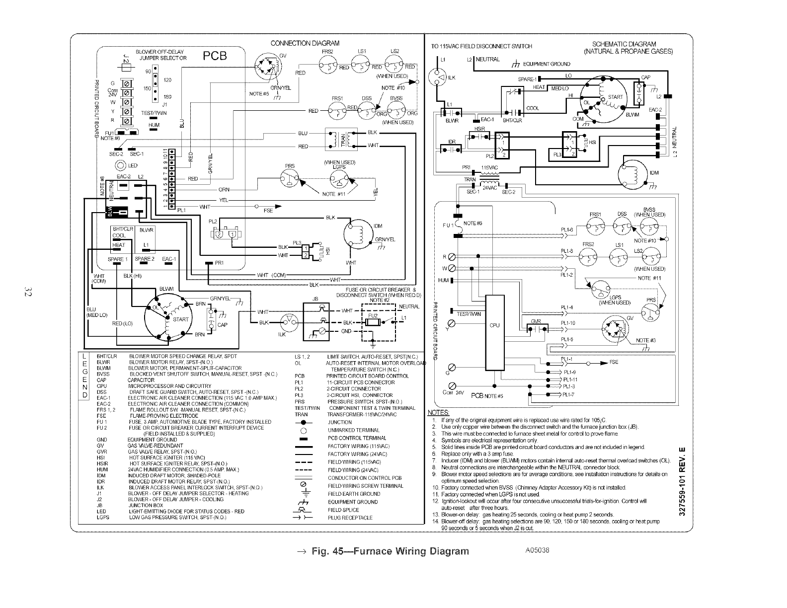
r_
WHT
(COM)
I
G
E
N
D
BLOV'_:R OEF49ELAY
c. JUMPER SELECT OR
I'O
901
Com 150
24V 180
Jl
TEST/TVMN
i
HUM
FUI _ i
SEC-2 SEC-1
(_ LED
N EACh2 _
PCB
-FBCLR
_T
RE 1 SPARE 2 EAC-I
i I
BLK (14) 1-
BLI_NM , L
RED (LO) \ _ Jp
\_ _NN
GRN/YEL
NOTE #5 /f[7
CONNECTIONDIAGRAM
ERS2 LS1 LS2
RIED _ RED _ RED"
(_N USED)
NOTE#_0_
FRS1 DSS BVSS I
O__ORG_OR i
RED ]
RED G
mEN USED)
BHT/CLR BLOWER MOTOR SPEED CHANGE REIJ_Y, SPDT
BLWR BLOWER MOTOR RELAY, SPST-(N O )
BLWM BLOWER MOTOR, PERMANENT-SPUT-CAPACITOR
BVSS BLOCKED VENT SHUTOFF SWITCH M_,NUAL RESET SPST (N C )
CAB CAPACITOR
CPU MICROPROCESSOR AND CiRCUiTRY
DSS DRAFT SAFE GUARD SW1TCH, AUTO-RESET, SPST-(N C)
EAC-1 ELECTRON C AiR CLEANER CONNECT ON ( 5 VAC 10 AMP MAX )
EAC-2 ELECTRON C AIR CLEANER CONNECT ON (COMMON)
FRSE2 FLAN1E ROLLOUT SW MANUAL RESET SPST (N C ) TESTEIWIN COMPONENT TEST & TWiN TERMINAL
FSE FLAN1E PROVING ELECTRODE TRAN TRANSFORMER 115VAC/24VAC
FU 1 FUSE 3 AMP A_OMOTI_ BLADE _PE FACTORY INST_LED _ JUNCTION
FU 2 FUSE OR CiRCUiT BR_KER CURRENT INTERRUPT D_]CE
(FIELD INSTN.I ED & SUPP! lED) O UND_RKED TERMI_L
GND EQUIPMENT GROUND i PCB CONTROt TERMiN_
GV _S _LVE-REDUNDANT i FACTORY W_RING (115£AC)
GVR GAS VALVE RELAY, SPST (N O ) FACTORY _ RING (24Y_C)
HSI HOT SURFACE iGNiTER (115 VAC)
HSIR HOT SURFACE IGNITER RELAY, SPST-(N O) F ELD W1R NG ( 5VAC)
HUM 24VAC HUMIDIFIER CONNECTION (0 5 AMP MAX) .... FIELD W1RING (24VAC)
IDM INDUCED DRAFT MOTOR, SHADED POLE CONDUCTOR ON CONTROL PCB
IDR NDUCED DRAFT MOTOR RELAY, SPST-(N O / _ FIELD W1R]NG SCREW TERMINAL
ILK BLO'WER ACCESS PANEL NTERLOCK S'_ITCH SPST-(N O ) j_
J1 BLOWER - OFF DELAY JUMPER SELECTOR - HEAl] NG _ FIELD EARTH GROUND
J2 BLOWER - OFF DELAY JUMPER - COOLING _-z EQUIPMENT GROUND
JB JUNCTION BOX
LED LIGHT-EMITTING DIODE FOR STATUS CODES - RED _ FIELD SPLICE
LGPS LOW GAS PRESSURE S'B_ITCH SPST-(N O ) -"-) )--- PLUG RECEPTACLE
('_NHEN USED)
PRS LGPS
I
BLK
]DM
_.__. GR_N/YEL
_dT
,Z T , I I
BLK
FUSE OR CIRCUITBREAKER &
DISCONNECT SVMTCH (VVHEN REQ D)
JB NOTE #2
r ....... I
I a_ _I I I _I I I FU2 ILI
iLK /7_ "_" --- GND -I-- II
T
LS 1, 2 LIMIT SWITCH AUTO-BESET, SPST(N C )
OL AUTO RESET INTERNAL MOTOR OVERLO, _
TEMPERATURE SWITCH (NO)
PCB PRINTED CIRCUIT BOARD CONTROL
PL1 11-CIRCUIT PCB CONNECTOR
PL2 2-CIRCUIT CONNECTOR
PL3 2-CIRCUIT HSI, CONNECTOR
PRS PRESSURE SWITCH SPST-(N O )
TO 115VAC FIELD DISCONNECT SWITCH SCHEMATIC DIAGRAM
(NATURAL & PROPANE GASES
LI LtI NELrrRAL /_7 EQUIPMENT GROUND
• _ CAP
ILK SPARE I •.
MEDLO/\
L i HI START L2 I
co.co. i
HSIR I_
PR1 _ I
II
FUI ( NO_
R®
w®
HU
CoM 24v PCB NOTE#5
B'V'SS
FRS1 DSS (Vt,HEN USED)
PL_4_ q
_$2 LSl NOTE#10
_I_ LS2
I1[_) PL1-11
PL_-3
PLy-7
NOTES:
1 If any of the edginal equipment wlre is replaced u_ wire rated for 105 iC
2 Use only copper wire betwee_ the disconnect switch aed the fumace junctic_ box (JB)
3 This wire must be comected to furnace sheet metal for control to prove flame
4 Symbols are electrical representation only
5 Solid lines inside PCB are pnnted c4rcuit board coeductors and are not included in legeed ILl
6 Replace only with a 3 amp fuse
7 Inducer (IDM) and blower (BLV1A_I) motcrs contain intem_ autodeset thermal ovedoad switches (OL)
8 Nentral connections are interd_angeable within the NELFIPdkL connector block
9 Blower motor speed selectiops ae for average conditions, see installation instlllctions for details on __
optimum speed selection 0
10 Factory connected when BVSS (Chimney Adapter Accessory Kit) is nct installed
11 Factory connected when LGPS is not used
12 Ignition-lockout will occur after four consecutive unsuccessful trials-fordg_ition Control will
autoceset after three hours ¢,4
13 Blower-on delay: gas heating 25 seconds, cooling or heat pump 2 seconds e_
14 Blower-off delay: gas heating s_ections are 9& 120,150 or 180 seconds ccoling or heat pump
90 seconds or 5 seconds when J2 is cut
-> Fig. 4S--Furnace Wiring Diagram A05038
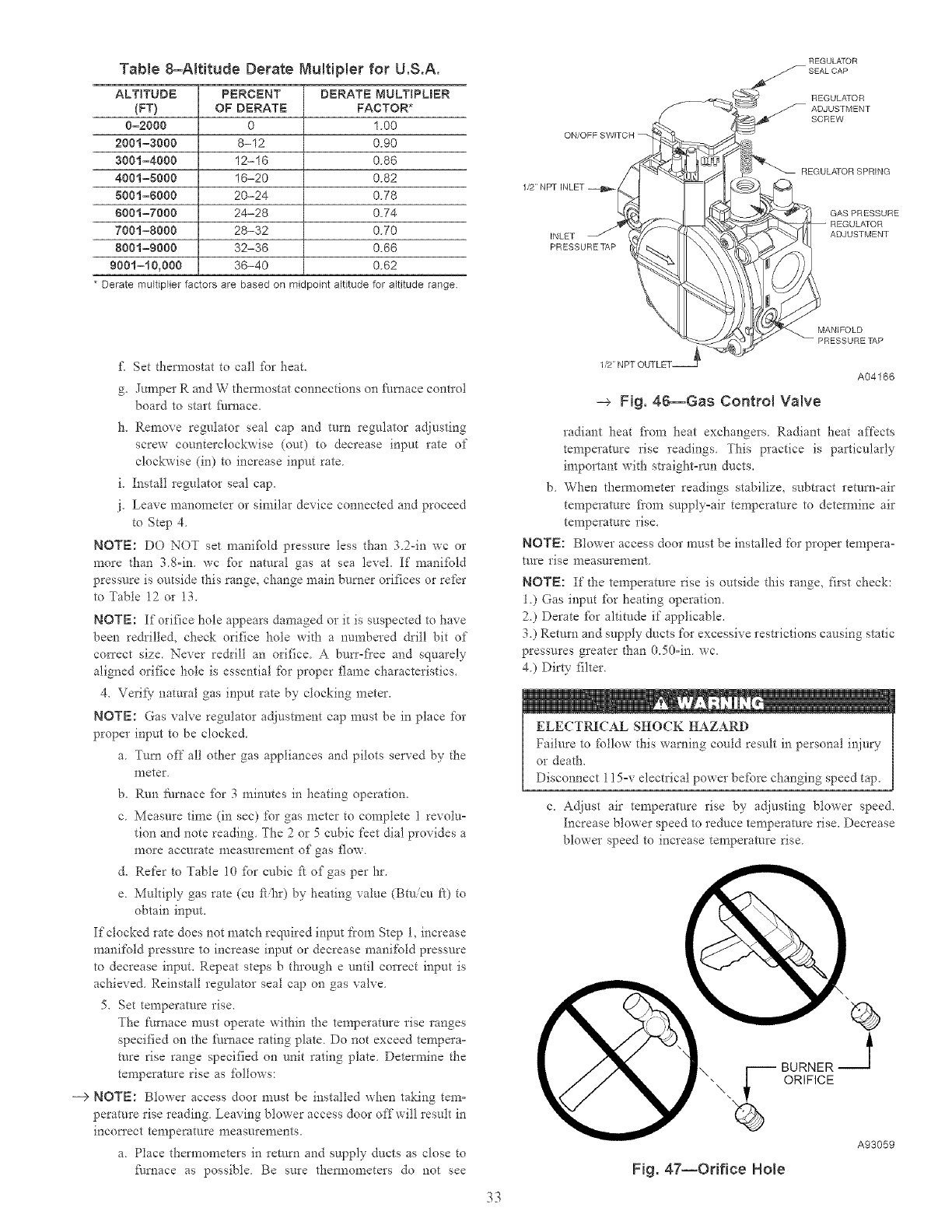
TaNe 8-AIt{tude Derate MuR{Ner for U.S.A.
ALTITUDE PERCENT DERATE MULTIPLBER
(FT} OF DERATE FACTOR*
0-2000 0 1.00
2001=3000 8-12 0.90
3001=4000 12-16 0.86
4001=8000 16-20 0.82
5001=6000 20-24 0.78
6001=7000 24-28 0.74
7001=8000 28-32 0.70
8001=9000 32-36 0.66
9001=t0,000 36-40 0.62
* Derate multiplier factors are based on midpoint altitude for altitude range
ON/OFF
1/2 NPT INLET
INLET
PRESSURE%&P
REGULATOR
REGULATOR
ADJUSTMENT
SCREW
REGULATOR SPRING
GASPRESSURE
ADJUSTMENT
£Set them_ostat to call fk_rheat.
g. Jumper R and W thermostat connections on fk/mace cont*ol
board to start fi/mace.
1"1.Remove regulator seal cap and turn regulator adjusting
screw counterclockwise (out) to decrease input rate of
clockwise (in) to increase input rate
i. Install regulator seal cap.
.i. Leave manomete* or similar device connected and proceed
to Step 4
NOTE: DO NOT set manifPld pressure less than 32-in wc or
more than 38=in. wc fbr natural gas at sea level. If' manifold
pressure is outside this range, change main burner orifices or refer
to Table 12 or 13.
NOTE: If'orifice hole appears damaged or it is suspected to have
been re&illed, check orifice hole with a numbered &ill bit of
cmTect size. Never redrill an orifice A bun'-flee and squarely
aligned orifice hole is essential for proper flame cha*acteristics.
4. Veri*}' natural gas input rate by clocking meter.
NOTE: Gas valve regulator adjustment cap must be in place for
proper input to be clocked
a Turn off all other gas appliances and pilots so*red by the
meter
b. Run iqu_ace fPr 3 minutes in heating operation.
c Measm'e time (in sec) for gas meter to complete 1 revolu=
tion and note reading The 2 or 5 cubic feet dial provides a
nlore accurate nleasnrenlent of gas flow.
d. Refer to Table 10 fbr cubic f_ of gas per hr.
e. Multiply gas rate (cu f_&r) by heating value (Btuicu ft) to
obtain input.
If clocked rate does not match required input from Step 1, increase
manifold pressure to increase input or decrease manifold pressure
to decrease input. Repeat steps b through e until correct input is
achieved. Reinstall regulator seal cap on gas valve.
5. Set temperatore rise.
The furnace must operate within t!_etemperature rise ranges
specified on the filmace rating plate. Do not exceed tempera-
ture rise range specified on unit rating plate. Determine the
temperature rise as follows:
--> NOTE: Blower access door must be installed when taking tern-
perature rise reading. Leaving blower access door offwill result in
incot_'ect temperature nleasnrements.
a. Place thermometers in remm and supply ducts as close to
_/rnace as possible. Be sure them_ometers do not see
33
1/2 NPT OUTLET_
MANIFOLD
PRESSURE TAP
A04166
-_ Fig. 46--Gas Control Valve
radiant heat fi'om heat exchangers Radiant heat affects
temperature rise readings This practice is particularly
important with straight-rtm ducts,
b When them_ometer readings stabilize, subtlact return-air
temperature fiom supply=air temperature to detem_ine air
temperature rise.
NOTE: Blower access door must be installed for proper tempera-
ture rise measurement
NOTE: If the temperature rise is outside this range, first check:
1.) Gas input _br heating operation.
2.) Derate _Pr altitude if applicable.
3.) Return and supply ducts for excessive restrictions causing static
pressures greater than 0.50=in. wc.
4.) Dirty filter.
ELECTRICAL SHOCK HAZARD
Failure to follow this warning could result in personal injury
or death.
Disconnect 115=v electrical power befPre changing speed tap.
c Adjust air temperature rise by adjusting blo_er speed.
Increase blower speed to reduce temperature rise. Decrease
blower speed to increase temperature rise
\
BURNER J
UORIFICE
Fig. 47--Orifice Hole
A93059
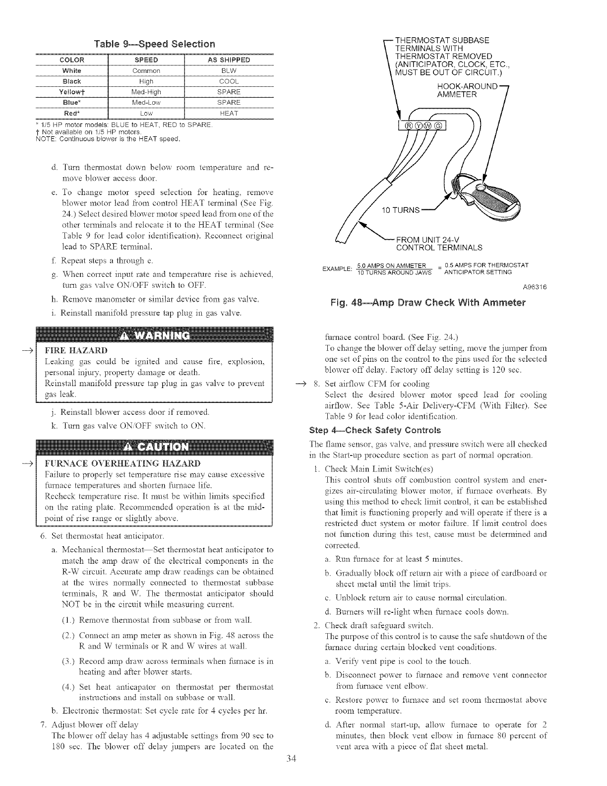
Table 9--Speed Selection
COLOR SPEED AS SHIPPED
White Common BLW
Black High COOL
Yel]owt Med-High SPARE
Blue* Med-Low SPARE
Red* Low HEAT
* 1/5 HP motor models: BLUE to HEAT, RED to SPARE
t Not available on 1/5 HP motors.
NOTE: Continuous blower is the HEAT speed.
--€
--€
& Turn thermostat down below room temperature and re-
move blowm access door.
e. To change motto speed selection fbr heating, remove
blower motor lead fiom contlol HEAT terminal (See Fig.
24.) Select desired blower motor speed lead fi'om one of the
other terminals and relocate it to dte HEAT terminal (See
Table 9 for lead color identification). Reconnect original
lead to SPARE terminal.
fi Repeat steps a through e.
g. When correct input rate and temperature rise is achieved,
mrn gas valve ON/OFF switch to OFF
h. Remove manometer or similar device f?om gas valve.
i. Reinstall manifold pressu*e tap plug in gas valve.
FIRE HAZARD
Leaking gas could be ignited and cause fire, explosion,
personal injury, property damage or death.
Reinstall manifold pressure tap plug in gas valve to prevent
gas leak.
j. Reinstall blower access door if remoxed
k. Turn gas valve ONOFF switch to ON.
F1. RNA(E OVERHEATING HAZARD
Failure to properly set temperature rise may cause excessive
furnace temperatures and shorten fi/mace life.
Recheck temperature rise. It must be within limits specified
on the rating plate Recommended operation is at the mid=
point of rise range or slightly above
6. Set thermostat heat anticipator.
a. Mechanical thermosta_Set thermostat heat anticipator to
match the amp draw of the electrical components in the
R-W circuit Accurate amp &aw readings can be obtained
at the wires nom_ally connected to themaostat subbase
terminals, R and W The thermostat anticipator should
NOT be in the circuit while measuring cmTent.
(1) Remove thermostat fi'om subbase or fl'om wall
(2) Connect an amp meter as shown in Fig. 4g across the
R and W terminals or R and W wires at wall
(3) Record amp &aw across terminals when furnace is in
heating and after blower starts.
(4) Set heat anticapator on thermostat per thermostat
instructions and install on subbase or wall.
b. Electronic thermostat: Set cycle rate for 4 cycles per hr.
7. Adjust blower off delay
The blower off delay has 4 adiustable settings fi'om 90 sec to
180 sec. The blower off delay jumpers are located on the
-->
34
TERMINALS WITH
THERMOSTAT REMOVED
(ANITICIPATOR, CLOCK, ETC.,
MUST BE OUT OF CIRCUIT.)
AMMETER
10 TURNS
FROM UNIT 24-V
CONTROL TERMINALS
EXAMPLE: 50 AMPS ON AMMETER = 0.5 AMPS FOR THERMOSTAT
10 TURNS AROUND JAWS ANTICIPATOR SETTING
A96316
Fig. 48--Amp Draw Check With Ammeter
fhrnace contlol board. (See Fig 24.)
To change the blower off delay setting, move the jumper from
one set of pins on the control to the pins used for the selected
blower off delay. Factory off delay setting is 120 sec.
8. Set airflow CFM fbr cooling
Select the desired blower motor speed lead for cooling
airflow. See Table 5=Air Delivery=CFM (With Filter). See
Table 9 for lead color identification.
Step 4_Cheek Safety Controls
The flame sensor, gas yah-e, and pressure switch were all checked
in d_e Start=up procedure section as part of normal operation.
1. Check Main Limit Switch(es)
This control shuts off combustion control system and ener-
gizes air-circulating blower motor, if fhrnace overheats. By
using this method to check limit control, it can be established
that limit is functioning properly and will operate if there is a
restricted duct system or motor failure. If limit contlol does
not fhnction during this test, cause must be determined and
corrected
a. Rm'_ furnace for at least 5 minutes.
b. Gradually block off return air with a piece of cardboard or
sheet metal until the limit trips.
c. Unblock return air to cause normal circulation.
d. Burners will re-tight when fhrnace cools down.
2. Check &aft safeguard switch.
The purpose of d-fis contlol is to cause the safk shutdown of the
furnace during cellain blocked vent conditions.
a. Vet!f) vent pipe is cool to the touch.
b. Disconnect power to f:urnace and remove vent connector
fi'om furnace vent elbow.
c. Restore power to fhrnace and set room thermostat above
roonl temperature.
d. After nom_al start-up, allow furnace to operate for 2
minutes, then block vent elbow in fllrnace 80 percent of
vent area with a piece of flat sheet metal
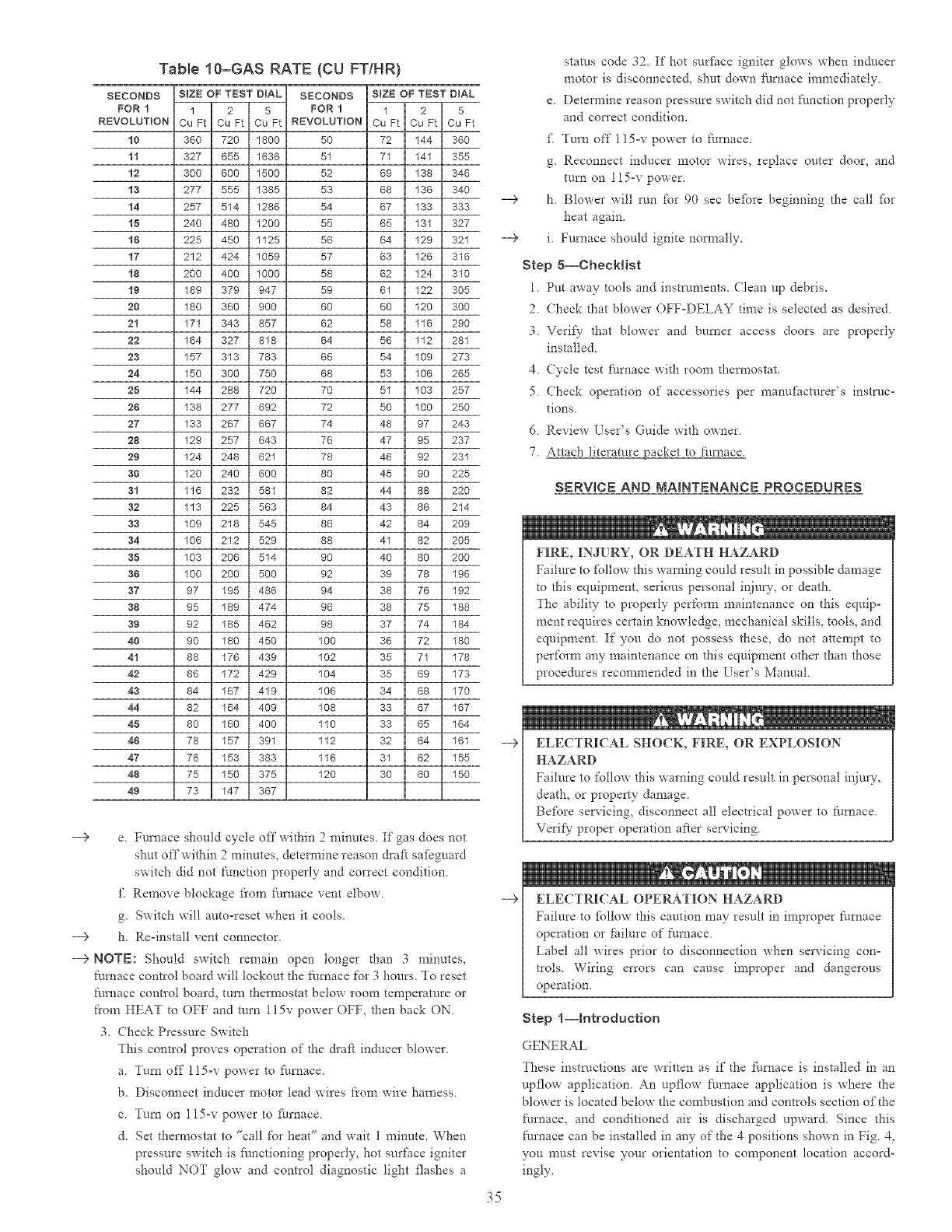
Tab{e 10-GAS RATE (CU FTfHR)
SECONDS SIZE OF TEST DIAL SECONDS SIZE OF TEST DIAL
FOR 1 1 2 5 FOR 1 1 2 5
REVOLUTION Cu Ft Cu Ft Cu Ft REVOLUTION Cu Ft Cu Ft Cu Ft
10 360 720 1800 50 72 144 360
11 327 655 1636 51 71 141 355
12 300 600 1500 52 69 138 346
13 277 555 1385 53 68 136 340
14 257 514 1286 54 67 133 333
15 240 480 1200 55 65 131 327
16 225 450 1125 56 64 129 321
17 212 424 1059 57 63 126 316
18 200 400 1000 58 62 124 310
19 189 379 947 59 61 122 305
20 180 360 900 60 60 120 300
21 171 343 857 62 58 116 290
22 164 327 818 64 56 112 281
23 157 313 783 66 54 109 273
24 150 300 750 68 53 106 265
25 144 288 720 70 51 103 257
26 138 277 692 72 50 100 250
-->
27 133 267 667 74 48 97 243
28 129 257 643 76 47 95 237
29 124 248 621 78 46 92 231
30 120 240 600 80 45 90 225
31 116 232 581 82 44 88 220
32 113 225 563 84 43 86 214
33 109 218 545 86 42 84 209
34 106 212 529 88 41 82 205
35 103 206 514 90 40 80 200
36 100 200 500 92 39 78 196
37 97 195 486 94 38 76 192
38 95 189 474 96 38 75 188
39 92 185 462 98 37 74 184
40 90 180 450 100 36 72 180
41 88 176 439 102 35 71 178
42 86 172 429 104 35 69 173
43 84 167 419 106 34 68 170
44 82 164 409 108 33 67 167
45 80 160 400 110 33 65 164
46 78 157 391 112 32 64 161
47 76 153 383 116 31 62 155
48 75 150 375 120 30 60 150
49 73 147 367
---5 e Furnace should cycle off within 2 minutes. If gas does not
shut offwithin 2 minutes, detem_ine reason &aft safeguard
switch did not function properly and correct condition.
f\ Remove blockage fl'om furnace vent elbow.
g. Switch will autooreset when it cools.
--> h. Reoinstall vent connector.
---5 NOTE: Should switch remain open longer than 3 minutes,
furnace control board will lockout the f:urnace for 3 hours. To reset
furnace control board, turn thermostat below room temperature or
from HEAT to OFF and mrn 115v power OFF, then back ON.
3. (hock Pressure Switch
This contlol proves operation of the &aft inducer blower.
a. Turn off l!5ov power to fhrnace.
b. Disconnect inducer motor lead wires from wire harness.
c. Turn on 115or power to furnace.
d. Set thermostat to "call for heat" and wait 1 minute. When
pressure switch is flmctioning properly, hot surface igniter
should NOT glow and control diagnostic light flashes a
--€
35
status code 32. If hot surfSce igniter glows when inducer
motor is disconnected, shut down furnace immediately
e DeteImine reason pressure switch did not function properly
and con'ect condition.
f\ Turn off 115or power to ft_rnace.
g. Reconnect inducer motor wires, replace outer door, and
turn on 115-v power.
h. Blower will run for 90 sec befbre beginning the call fbr
heat again.
i. Furnace should ignite nom_ally.
Step 5--ChecHist
1 Put away tools and instruments. Clean up debris.
2. (hock that blower OFFoDELAY time is selected as desired.
3. Verii) that blower and burner access doors are properly
installed.
4 (ycle test fhmac¢ with room thermostat.
5. (hock operation of accessories per manuitacturer's instruc=
tions
6 Review /se*'s Guide with owner
7 Attach literature packet to fhmace.
SERVBCE AND MAINTENANCE PROCEDURES
FIRE, INJURY, OR DEATH HAZARD
Failure to fbllow this warning could result in possible damage
to this equipment, serious personal injury, or death
The ability- to properly perform maintenance on this equip°
ment requires certain knowledge, mechanical skills, tools, and
equipment. If you do not possess these, do not attempt to
perform any maintenance on this equipment other than those
procedures recommended in the User's Manual.
ELECTRICAL SHOCK, FIRE, OR EXPLOSION
HAZARD
Failure to follow this warning could result in personal injury,
death, or property damage
Before servicing_ disconnect all electrical power to ftlmace
Verif)- proper operation after servicing.
ELECTRICAL OPERATION HAZARD
Failure to fbllow this caution may result in improper furnace
operation or failure of tim_ace
Label all wires prior to disconnection when selwicing con-
tIols Wiring errors can cause improper and dangerous
operation.
Step l--htroduction
GENERAL
These instructions are written as if the furnace is installed in an
upflow application. An upflow furnace application is where the
blower is located below the combustion and controls section of the
furnace, and conditioned air is discharged upward. Since this
ff_rnace can be installed in any of the 4 positions shown in Fig 4,
you must revise your orientation to component location accord-
ingly.
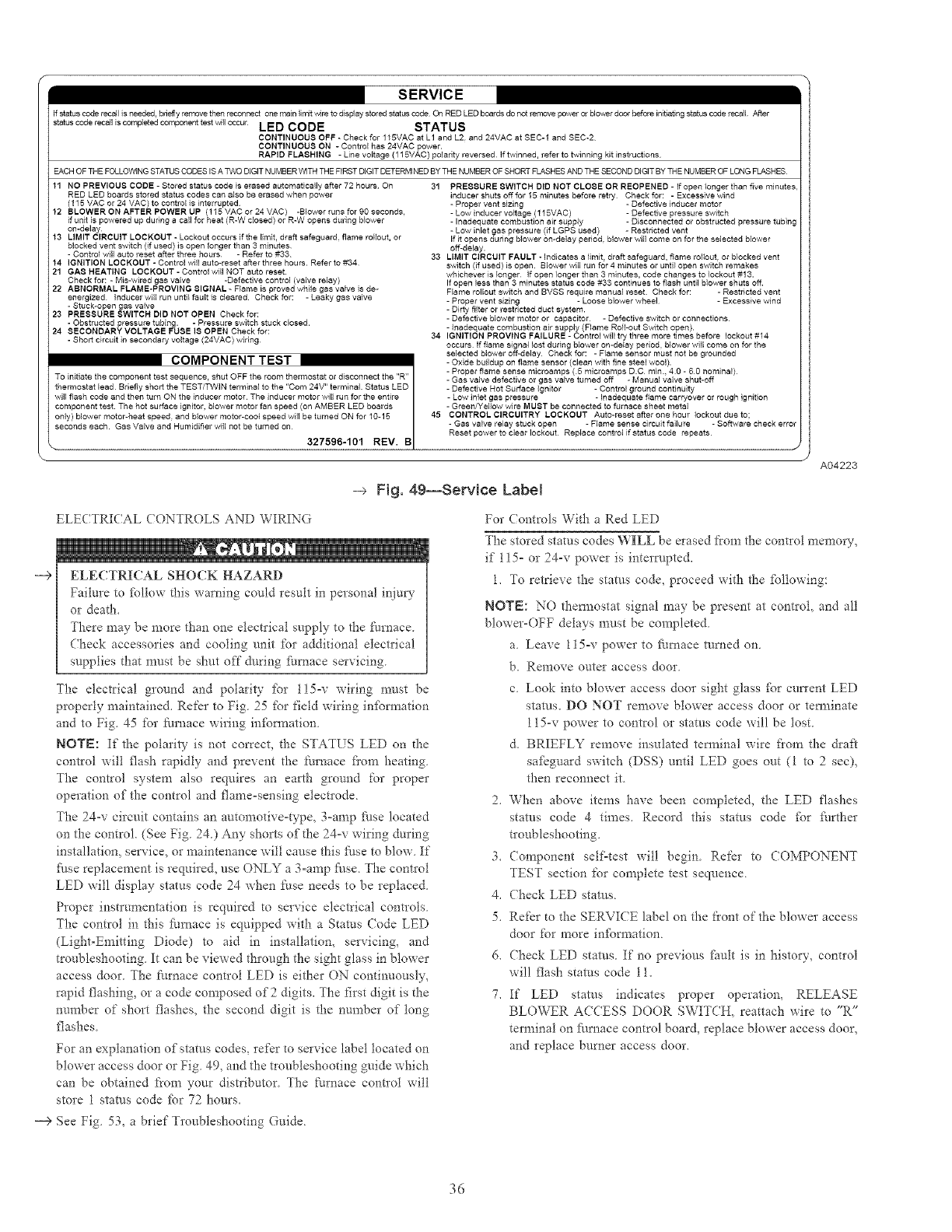
SERVICE
if status code recall is needed, bc_et]y remove then recoqnect one main Iirr_t vdre to display stored status code Of 1 RED LEO boards do not re_ove power or b_ower door before initiating status cede recall After
stafuscoderecalliscomplstedcomponenttestwlloccurLED CODE STATUS
CONTINUOUS OFF -Check for 115MAC at L1 and L2. and 24VAC at SEC-1 and SEC-2
CONTINUOUS ON - Control has 24VAC power.
RAPID FLASHING - Line vNtage (115VAC) poladty reversed If twinned, refer to twinning kit instructions
EACH OF THE FOLLOWING STATUS CODES IS A TWO DIGIT NUMBER VvlTH THE FIRST DIGIT DETERMINED BY THE NUMBER OF SHORT FLASHES AND THE SECOND DIGIT BY THE NUMBER OF LONG FLASHES
11 NO PREVIOUS CODE - Stored status code is erased automatically after 72 hours On 31 PRESSURE SWITCH DID NOT CLOSE OR RBOPENBD - If open longer than five minutes
RED LED boards stored status codes can also be erased when power
(115 VAC or 24 VAC) to control is interrupted
12 BLOWERONAFTERPOWERUP (115 VAC or 24 VAC) -Blower runs for 90 seconds,
if unit is powered up during a call for heat (R-W closed) or R-W opens during blower
on-delay
13 LIMIT CIRCUIT LOCKOUT - Lockout occurs if the limit, draft safeguard, flame rollout, or
blocked vent switch (if used) is open longer than 3 minutes
- Control will auto reset after three hours -Refer to #33 33
14 IGNITION LOCKOUT - Control wilJ auto-reset after three hours. Refer to #34
21 GAS HEATING LOCKOUT - Control will NOT auto reset.
Check for: -Mis-wired gas valve -Defective control (valve relay)
22 ABNORMAL FLAME-PROVING SIGNAL - Flame is proved while gas valve is de-
energized Inducer will run unti} fault is cleared. Check for: - Leaky gas valve
- Stuck-open gas valve
23 PRBSSURB SWITCH DID NOT OPEN Check for:
- Obstructed pressure tubing. - Pressure switch stuck dosed.
24 8BCONDARY VOLTAGB FUSB 18 OPEN Check for:
- Short circuit in secondary voltage (24VAC) wiring 34
COMPONENT TEST
To initiate the component test sequence, shut OFF the room thermostat or disconnect the "R"
thermostat lead Briefly short the TEST/TWIN terminal to the 'Corn 24V" terminal. Status LED
component test The hot surface ignitor, blower motor fan speed (on AMBER LED boards
will flash code and then turn ON the inducer motor The inducer motor will run for the entire
only) blower motor-heat speed, and blower motor-coo} speed will be turned ON for 10-15 I45
seconds each. Gas Valve and Humidifier will not be turned on I
I
327596-101 REV. B
\
inducer shuts off for I5 minutes before retry Check for: -Excessive wind
-Proper vent sizing -Defective inducer motor
-Low inducer voltage (I 15VAC) -Defective pressure switch
-Inadequate combustion air supply -Disconnected or obstructed pressure tubing
-Low inlet gas pressure (if LGPS used) - Restricted vent
If it opens dedng blower on-delay period¸ blower will come on for the selected blower
off-delay.
LIMIT CIRCUIT FAULT - Indicates a limit, draft safeguard, flame rol_out or blocked vent
switch (if used) is open. Blower will run for 4 minutes or until open switch remakes
whichever is longer If open longer than 3 minutes, code changes to lockout #13.
If open less than 3 minutes status code #33 continues to flash until blower shuts off
Flame rollout switch and BVSS require manual reset. Check for: - Restricted vent
- Proper vent sizing - Loose blower wheel¸ - Excessive wind
- Dirty filter or restricted duct system.
- Defective blower motor or capacitor¸ - Defective switch or connections¸
- Inadequate combustion air supply (Flame Roll-out Switch open).
IGNITION PROVING FAILURE - Control will try three more times before lockout #14
occurs¸ If flame signal lost during blower on-de_ay period, blower will come on for the
selected blower off-delay Check for: - Flame sensor must not be grounded
- Oxide buildup on flame sensor (clean with fine steel wool).
- Proper flame sense microamps (5 microamps DC rain., 40 - S0 nominal)
- Gas valve defective or gas valve turned off - Manual valve shut-off
- Defective Hot Surface Ignitor -Control ground continuity
- Low inlet gas pressure -Inadequate flame carryover or rough ignition
- Green/Yedow wire MUST be connected to furnace sheet metal
CONTROL CIRCUITRY LOCKOUT Auto-reset after one hour lockout due to;
- Gas valve relay stuck open - Flame sense circuit failure - Software check error
Reset power to clear lockout Replace control if status code repeats¸
J
1
A04223
-_ Fig. 49--Service Label
ELECTRICAL CONTROLS AND WIRING
--€ ELECTRICAL SHOCK HAZARD
Failure to follow this warning could result in personal injuQ'
or death.
There may be more than one electrical supply to the/_t_rnace.
Check accessories and cooling unit for additional electFical
supplies that must be shut off during furnace servicing.
The electrical ground and polarity fbr 115-v wiring must be
properly maintained. Refer to Fig. 25 fbr field wiring infbm_ation
and to Fig 45 for furnace wiring infi_rmation
NOTE: If the polarity is not correct, the STATUS LED on d-xe
control will flash rapidly and prevent the tk_mace fiom heating
The control system also requires an earth ground for proper
operation of the control and flameosensing electlode
The 24_v circuit contains an automotiveotype, 3°amp _klse located
on the control. (See Fig 24) Any shorts of the 24-v wiring during
installation, service, or maintenance will cause this fi/se to blow If
_k/se replacement is required, use ONLY a 3oamp J:k/se The control
LED will display status code 24 when fuse needs to be replaced
Proper instrumentation is required to service electrical controls
The control in this furnace is equipped with a Stares (ode LED
(Light-Emitting Diode) to aid in installation, servicing, and
troubleshooting It can be viewed through the sight glass in blower
access door The fm'nace control LED is either ON continuously,
rapid flashing, or a code composed of 2digits. The first digit is the
nm'nber of short flashes, the second digit is the number of tong
flashes
For an explanation of status codes, ref¢r to service label located on
blower access door or Fig 49_ and the tloubleshooting guide which
can be obtained from your distFibutor The ftmaace control will
store 1 stares code fbr 72 hours.
For (ontrols With a Red LED
The stored status codes WILL be erased from the control memory,
if 115- or 24-v power is interrupted.
1. To retrieve the stares code, proceed with the _bllowing:
NOTE: NO them_ostat signal may be present at control, and all
blower_OFF delays must be completed
a Leave l15ov power to fi_rcmce mined on
b. Remove outer access door
c Look into blower access door sight glass fbr current LED
stares. DO NOT remove blower access door or tem_inate
115_v power to control or stares code will be lost
d. BRIEFLY remove insulated terminal wire fiom the draft
safeguard switch (DSS) until LED goes out (1 to 2sec),
then reconnect it
2. When above items have been completed, the LED flashes
status code 4 times. Record this stares code fbr fi/rther
troubleshooting.
3. (omponent self=test will begin. Refer to COMPONENT
TEST section for complete test sequence.
4. Check LED stares.
5. Refer to d_e SERVICE label on the front of the blower access
door for more infbrmation.
6. Check LED status. If no previous fault is in history, control
will flash stares code 11.
7. If LED status indicates proper operation, RELEASE
BLOWER ACCESS DOOR SWITCH, reattach wire to "R"
terminal on fi/rnace control board, replace blower access door,
and replace burner access door.
-9 See Fig. 53, a brief Troubleshooting Guide
36
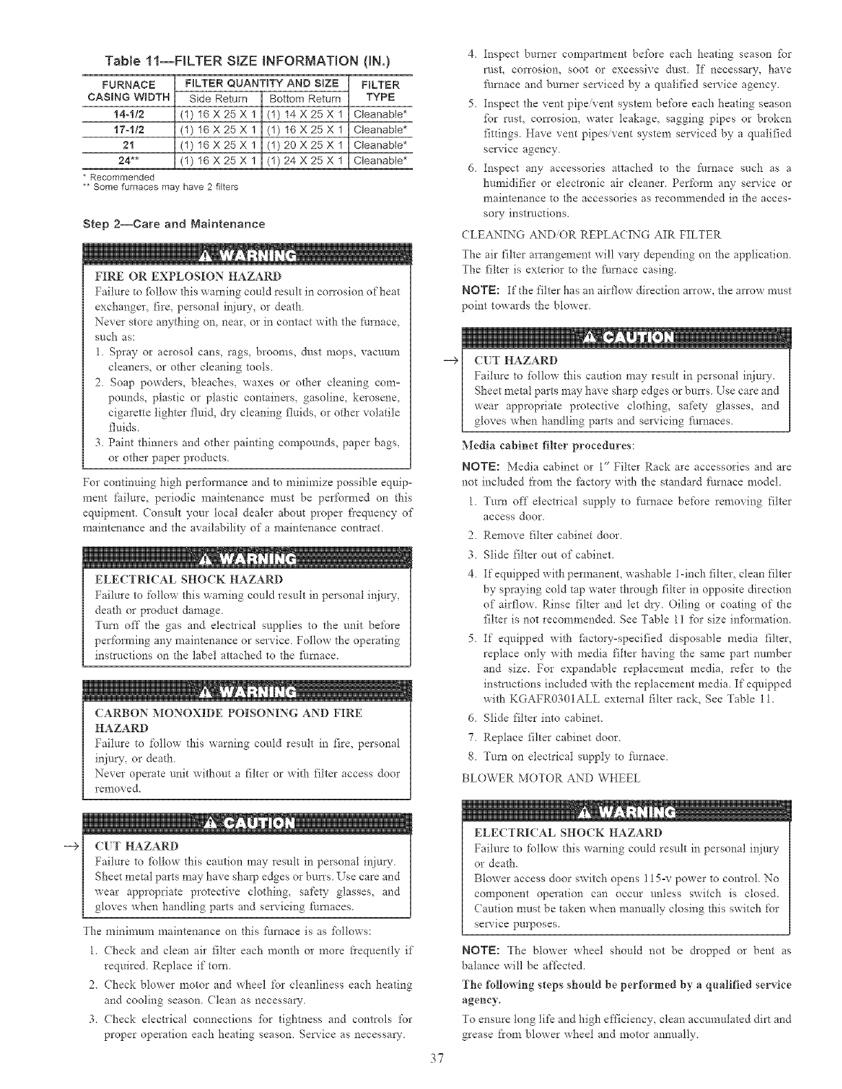
--€
TaNe l 1--FILTER SIZE _NFORMATION (iN.)
FURNACE
CASBNG W_DTH
14-1/2
17-1/2
21
24**
* Recommended
** Some furnaces may have 2 filters
FILTER QUANTITY AND S_ZE
Side Return Bottom Return
(1) 16X25X I (1) 14X25X 1
(1) 16X25X I (1) 16X25X 1
(1) 16X25X 1 (1) 20X25X 1
(I) 16X25X I (I) 24X25X 1
FILTER
TYPE
Cteanabte*
Cteanabte*
Cteanabte*
Cleanable*
Step 2--Care and Maintenance
FIRE OR EXPLOSION HAZARD
Failure to %llow this warning could result in corrosion of heat
exchanger, fire, personal inju_', or death
Never store anything on, near, or in contact with the I:t_rnace,
such as:
1. Spray or aerosol cans, rags, brooms, dnst mops, vacuum
cleaners, or other cleaning tools.
2. Soap powders, bleaches, waxes or other cleaning corn=
pounds, plastic or plastic containers, gasoline, kerosene,
cigarette lighter fluid, dry cleaning fluids, or other volatile
fluids.
3. Paint thinners and other painting compounds, paper bags,
or other paper products.
For continuing high per%rmance and to minimize possible equip=
ment fg_ilure, periodic maintenance must be performed on this
equipment. Consult your local dealer ahont proper fiequency of
maintenance and the availability of a maintenance contract
ELECTRICAL SHOCK HAZARD
Failure to follow this warning could result in personal injury,
death or product damage.
Turn off the gas and electlical supplies to the unit before
performing any maintenance or service Follow the operating
instructions on the label attached to the ftmaace.
(ARBON MONOXIDE POISONING AND FIRE
HAZARD
Failure to follow this warning could result in fire, personal
injury, or death
Never operate unit without a filter or with filter access door
removed.
1
(IT HAZARD
Failure to %llow this caution may result in personal iRiury
Sheet metal parts may have sharp edges or bun's Use care and
wear appropriate protective clothing, safety glasses, and
gloves when handling parts and servicing fimaaces.
The minimnn_ maintenance on this fm_aace is as %llows:
1. (hock and clean air filter each month or more fiequently if
required. Replace if torn.
2. Check blower motor and wheel for cleanliness each heating
and cooling season. Clean as necessm 7.
3. (hock electrical connections _br tighmess and controls for
proper operation each heating season. Service as necessm_-.
--€
37
4. Inspect burner compartment be%re each heating season %r
rnst, corrosion, soot or excessive dust. If necessa_, have
_ul_ace and burner serviced by a qualified service agency.
5 Inspect the vent pipe/vent system before each heating season
_br rust, corrosion, water leakage, sagging pipes or broken
fittings. Have vent pipes/vent system serviced by a qualified
service agency.
6. Inspect any accessories attached to the t_t_mace such as a
humidifier or electronic air cleaner. Pert'ram any service or
maintenance to the accessories as recommended in the acces-
so_- instractions.
CLEANING AND/OR REPLACING AIR FILTER
The air filter arrangement will vary depending on the application.
The filter is exterior to the J:i/mace casing.
NOTE: If the filter has an airflow direction an'ow, the arrow must
point towards the blower.
CUT HAZARD
Failure to %llow this caution may result in personal injury.
Sheet metal parts may have sharp edges or burrs Use care and
wear appropriate protective clothing, safety glasses, and
gloves when handling parts and sela'icing I:_/maces.
Media cabinet filter procedures:
NOTE: Media cabinet or 1" Filter Rack are accessories and are
not included t'rom the factory with the standard _ilrnace model
1 Turn off electIical supply to furnace before removing filter
access door.
2Remove filter cabinet door
3 Slide filter out of cabinet.
4 If equipped with permanent, washable 1-inch filter, clean filter
by spraying cold tap water through filter in opposite direction
of airflow. Rinse filter and let dry. Oiling or coating of the
filter is not recommended. See Table 11 for size int'ornaation.
5. If equipped with _bctory=specified disposable media filter,
replace only with media filter having the same part number
and size. For expandable replacement media, refer to the
instrnctions included with the replacement media. If equipped
with KGAFR0301ALL external filter rack, See Table 11.
6. Slide filter into cabinet.
7. Replace filter cabinet door.
8. Turn on electrical supply to ft_rnace.
BLOWER MOTOR AND WHEEL
ELECTRICAL SHOCK HAZARD
Failure to follow this warning could result in personal injury
or death.
Blower access door switch opens 115=v power to control. No
component operation can occur unless switch is closed.
(aution must be taken when manually closing this switch for
service purposes.
NOTE: The blower wheel should not be dropped or bent as
balance will be affected.
Tile foHmving steps should be performed by a quMified service
agenc?°
To ensure tong life and high eNciency, clean accumulated dirt and
grease from blower wheel and motor annually.
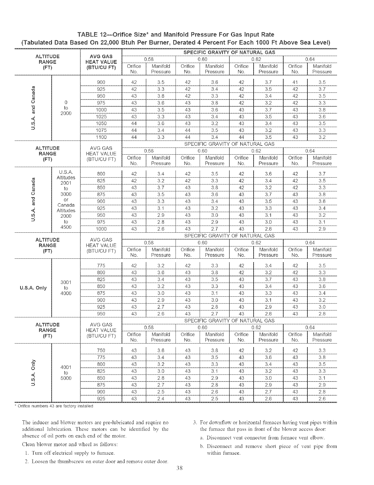
TABLE 12--Orifice Size* and Manifold Pressure For Gas input Rate
(Tabulated Data Based On 22,000 Btuh Per Burner, Derated 4 Percent For Each 1000 Ft Above Sea Level)
U.S.A. Only
ALTITUDE
RANGE
(FT)
o 0
-o to
2000
<:
AVG GAS
NEAT VALUE
(BTUiCU FT)
900
925
95O
975
1000
1025
1050
1075
1100
ALTITUDE AVG GAS
RANGE HEAT VALUE
(FT) (BTU/CU FT)
U.S.A.
Altitudes
"o 2001
to
_f
o 3000
"o or
Canada
Altitudes
2000
to
4500
8OO
825
85O
875
900
925
950
975
1000
ALTITUDE AVG GAS
RANGE HEAT VALUE
(FT) (BTU/CU FT)
3001
to
4000
775
8OO
825
85O
875
900
925
950
O
<:
ALTITUDE AVG GAS
RANGE HEAT VALUE
(FT) (BTU/CU FT)
4001
to
5000
* Orifice numbers 43 are factory installed
0.58
Orifice Manifold
No. Pressure
42 I
42 I
J
43 I
E
4:3 I
i
4:3 I
J
4:3 I
E
44 I
44 I
44 I
SPECIFIC GRAVITY OF NATURAL GAS
0.60 0.62 0.64
Orifice Manifold Orifice Manifold Orifice Manifold
No. Pressure No. Pressure No. Pressure
0.58
Orifice
No.
42 I
42 I
4:3 I
4_3 I
4,3 I
4:3 I
4,3 I
4:3 I
4:3 I
3.5 42
3.3 42
3.8 42
3.6 43
3.5 43
3.3 43
3.6 43
3.4 44
3.3 44
SPECIFIC GRAVITY
3.6 42
3.4 42
3.3 42
3.8 42
3.6 43
3.4 43 3.5
3.2 43 3.4
3.5 43 3.2
3.4 44 3.5
OF NATURAL GAS
Manifold
Pressure
3.7 41 3.5
3.5 42 3.7
3.4 42 3.5
3.2 42 3.3
3.7 43 3.8
43 3.6
43 3.5
43 3.3
43 3.2
0.60 0.62 0.64
Orifice Manifold Orifice Manifold Orifice Manifold
No. Pressure No. Pressure No. Pressure
3.4 42 3.5 42
3.2 42 3.3 42
3.7 43 3.8 42
3.5 43 3.6 43
3.3 43 3.4 43
3.1 43 3.2 43
2.9 43 3.0 43
2.8 43 2.9 43
2.6 43 2.7 43
0.58
Orifice Manifold
No. Pressure
42 I
J
43 I
E
43 I
E
43 I
J
43 I
E
43 I
E
43 I
J
4:3 I
3.3
3.1
3.0
2.8
SPECIFIC GRAVITY OF NATURAL GAS
3.6 42 3.7
3.4 42 3.5
3.2 42 3.3
3.7 43 3.8
3.5 43 3.6
43 3.4
43 3.2
43 3.1
43 2.9
0.60 0.62 0.64
Orifice Manifold Orifice Manifold Orifice Manifold
No. Pressure No. Pressure No. Pressure
0.58
Orifice
No.
750 43
775 43
800 43
825 43
850 43
875 43
900 43
925 43
3.2 42
3.6 43
3.4 43
3.2 43
3.0 43
2.9 43
2.7 43
2.6 43
SPECIFIC GRAVITY
3.3 42
3.8 42
3.5 43
3.3 43
3.1 43 3.3
3.0 43 3.1
2.8 43 2.9
2.7 43 2.8
OF NATURAL GAS
Manifold
Pressure
3.4 42 3.5
3.2 42 3.3
3.7 43 3.8
3.4 43 3.6
43 3.4
43 3.2
43 3.0
43 2.8
0.60 0.62 0.64
Orifice Manifold Orifice Manifold Orifice Manifold
No. Pressure No. Pressure No. Pressure
3.6 43 3.8 42
3.4 43 3.5 43
3.2 43 3.3 43
3.0 43 3.1 43
2.8 43 2.9 43
2.7 43 2.8 43
2.5 43 2.6 43
2.4 43 2.5 43
3.2
3.6
3.4
3.2
3.0
2.9
2.7
2.6
42
43
43
43
43
43
43
43
3.3
3.8
3.5
3.3
3.1
2.9
2.8
2.6
The inducer and blower motors are pro-lubricated and require no
additional lubrication. These motors can be identified by the
absence of oil ports on each end of the motor.
(?lean blower motor and wheel as fbllows:
1. Turn off electrical supply to furnace.
2. Loosen the thumbscrew on outer door and remove outer door.
38
For downflow or horizontal filrcmces having vent pipes within
the furnace that pass in fiont of the blower access door:
a Disconnect vent connector flora fire, ace vent elbow.
b. Disconnect and remove short piece of vent pipe from
within i_/rnace,
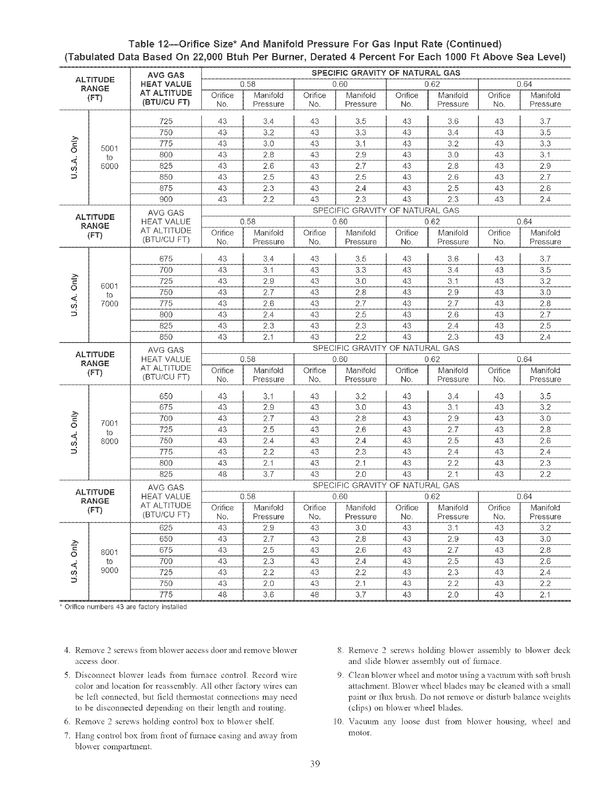
Table 12--Orifice Size* And Nanifold Pressure For Gas input Rate (Continued)
(Tabulated Data Based On 22,000 Btuh Per Burner, Derated 4 Percent For Each 1000 Ft Above Sea Level)
ALTITUDE
RANGE
{FT)
AVG GAS
NEAT VALUE
AT ALTITUDE
{BTU/CU FT) Orifice
No. Orifice
No.
725
75O
775
800
825
85O
875
9OO
AVG GAS
HEAT VALUE
AT ALTITUDE
(BTU/CU FT)
43 43
43 43
43 43
O 5001
to 43 43
m@ 6000 43 43
43 43
43 43
43 43
Orifice
No.
675
7OO
725
75O
775
80O
825
85O
AVG GAS
HEAT VALUE
AT ALTITUDE
(BTU/CU FT)
0.58
l ManifoldPressure
3.4
3.2
3.0
2.8
2.6
2.5
2.3
2.2
0.62
ManifoldPressure
43 3.6
43 3.4
43 3.2
43 3.0
43 2.8
43 2.6
43 2.5
43 2.3
NATURAL GAS
0.62
ALTITUDE
RANGE
(FT) Orifice
No.
43 43
43 43
43 43
O 6001
to 43 43
_ 7000 43 43
43 43
43 43
43 43
0.58
l ManifoldPressure
3.4
3.1
2.9
2.7
2.6
2.4
2.3
2.1
Orifice
No.
ALTITUDE
RANGE
(FT) Orifice
No.
43 43
43 43
43 43
O 7001
to 43 43
_ 8000 43 43
43 43
43 43
48 43
0.58
l Manifold
Pressure
3.1
2.9
2.7
2.5
2.4
2.2
2.1
3.7
0.58
Manifold
Pressure
2.9
2.7
2.5
2.3
2.2
2.0
3.6
SPECIFIC GRAVITY OF NATURAL GAS
0.60
Orifice / Manifotd Orifice
No. J Pressure No.
43 3.5
43 3.3
43 3.1
43 2.9
43 2.7
43 2.5
43 2.4
43 2.3
SPECIFIC GRAVITY OF
0.60
Orifice I Marfifold Orifice J ManifoldNo. Pressure No. Pressure
43 3.5 43 3.6
43 3.3 43 3.4
43 3.0 43 3.1
43 2.8 43 2.9
43 2.7 43 2.7
43 2.5 43 2.6
43 2.3 43 2.4
43 2.2 43 2.3
SPECIFIC GRAVITY OF NATURAL GAS
0.60 0.62
Orifice _ Manifotd Orifice Manifold
No. _ Pressure No.
43 3.2 43
43 3.0 43
43 2.8 43
43 2.6 43
43 2.4 43
43 2.3 43
43 2.1 43
43 2.0 43
SPECIFIC GRAVITY OF NATURAL GAS
0.60 0.62
Orifice
No.
43
43
43
43
43
43
48
Manifold
Pressure
3.0
2.8
2.6
2.4
2.2
2.1
3.7
Orifice
No.
43
43
43
43
43
43
43
J Pressure
3A
3.1
2.9
2.7
2.5
2.4
2.2
2.1
Manifold
Pressure
3.1
2.9
2.7
2.5
2.3
2.2
2.0
Orifice
No.
43
43
43
43
43
43
48
65O
675
7OO
725
75O
775
8OO
825
AVG GAS
HEAT VALUE
AT ALTITUDE
(BTU/CU FT)
625
65O
675
7OO
725
75O
775
ALTITUDE
RANGE
(FT}
O 8001
4 to
9000
Orifice
No.
43
43
43
43
43
43
43
0.64
l ManifoldPressure
3.7
3.5
3.3
3.1
2.9
2.7
2.6
2.4
0.64
l ManifoldPressure
3.7
3.5
3.2
3.0
2.8
2.7
2.5
2.4
0.64
l Manifold
Pressure
3.5
3.2
3.0
2.8
2.6
2.4
2.3
2.2
0.64
Manifold
Pressure
3.2
3.0
2.8
2.6
2.4
2.2
2.1
* Orifice numbers 43 are factory installed
4, Remove 2 screws i:i"om blower access door and remove blower
access door
5. Disconnect blower leads from f_/rnace contlol Record wire
color and location _k_rreassembly. All other factory wires can
be left connected, but field tiaem_ostat connections may need
to be disconnected depending on their length and routing.
6. Remove 2screws holding control box to blower shel£
7. Hang control box from fiont of furnace casing and away from
blower compartment.
g. Remove 2 screws holding blower assembly to blower deck
and slide blower assembly out of ftmaace.
9 (;lean blower wheel and motor using a vacuum with soft brush
attaciament Blower wiaeel blades may be cleaned with a small
paint or flux brusia. Do not remove or disturb balance weights
(clips) on blower wiaeel blades
10 Vacuum any loose dust fiom blower housing_ wheel and
nlotor.
39
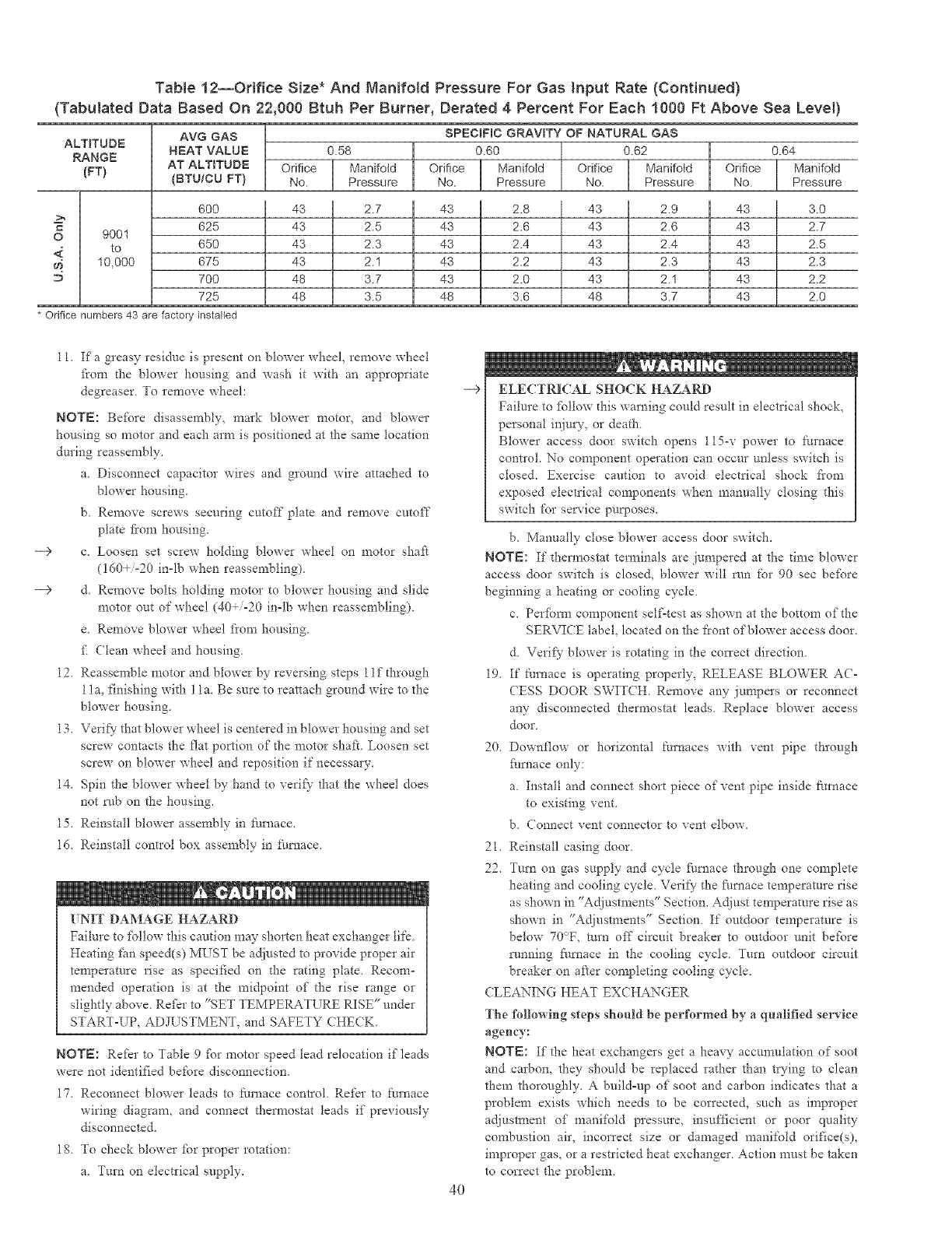
Table 12--Orifice Size* And Manifold Pressure For Gas input Rate (Continued)
(Tabulated Data Based On 22,000 Btuh Per Burner, Derated 4 Percent For Each 1000 Ft Above Sea Level)
ALTITUDE
RANGE
(FT}
AVG GAS
NEAT VALUE
AT ALTITUDE
(BTU/CU FT}
SPECIFIC
0.60
Orifice
No.
i Orifice
No.
43
43
43
43
48
48
0.58
Manifold
Pressure
2.7
2.5
2.3
2.1
3.7
3.5
GRAVITY OF NATURAL GAS
0.62
Orifice
No.
Manifold
Pressure
2.8
2.6
2.4
2.2
2.0
3.6
Orifice Manifotd
No. Pressure
43 2.9
43 2.6
43 2.4
43 2.3
43 2.1
48 3.7
600 43 43
c 625 43 43
O 9001
to 650 43 43
m 10,000 675 43 43
D 700 43 43
725 48 43
0.64
Manifold
Pressure
3.0
2.7
2.5
2.3
2.2
2.0
* Orifice numbers 43 are factory installed
___>
___>
11. If a greasy residue is present on blower wheel, remove wheel
from d_e blower housing and wash it with an appropriate
degrease> To remove wheel:
NOTE: Befbre disassembly, mark blower motor, and blower
housing so motor and each arm is positioned at the same location
during reassembly.
a. Disconnect capacitor wires and ground wire attached to
blower housing.
b. Remove screws securing cutoff plate and remove cutoff"
plate from housing.
c. Loosen set screw holding blower wheel on motor shaft
(160+/-20 in°lb when reassembling).
d. Remove bolts holding motor to blower housing and slide
motor out of wheel (40÷/-20 in-lb when reassembling).
e. Remove blower wheel fiom housing.
f Clean wheel and housing.
12. Reassemble motor and blower by reversing steps 1if d-_rough
1 in, finishing with 1 la. Be sure to reattach ground wire to the
blower housing.
13. Verif) that blower wheel is centered in blower housing and set
screw contacts the flat portion of d-_emotor shaft. Loosen set
screw on blower wheel and reposition if necessary.
14. Spin the blower wheel by hand to verif}- that the wheel does
not tab on the housing.
15. Reinstall blower assembly in fhrnace.
16. Reinstall control box assembly in f_/mace.
[NIT DAMAGE HAZARD
Failure to £bllow this caution may shorten heat exchanger life
Heating £m speed(s) MUST be adjusted to provide proper air
temperature rise as specified on d_e rating plate. Recom°
mended operation is at d-_e rni@oint of the rise range or
slightly above Refer to "SET TEMPERATURE RISE" under
START-UP, ADJUSTMENT, and SAFETY CHECK.
NOTE: Refer to Table 9 fbr motor speed tend relocation if leads
were not identified before disconnection.
17. Reconnect blower leads to fimaace control Refer to furnace
wiring diagram, and connect them_ostat leads if previously
disconnected.
18. To check blower fbr proper rotation:
a. Turn on electrical supply.
-->
4O
ELECTRICAL SHOCK HAZARD
Failure to fbllow this warning could result in electrical shock,
personal injury, or death
Blower access door switch opens 115-v power to furnace
contIoL No component operation can occur unless switch is
closed. Exercise caution to avoid electrical shock from
exposed electrical components when manually closing this
switch for service purposes.
b. Manually close blower access door switch.
NOTE: If d_em_ostat temainals are jumpered at the dine blower
access door switch is closed, blower wilt run for 90 sec befbre
beginning a heating or cooling cycle
c. Perfbrm component self-test as shown at the bottom of the
SERVI(E label, located on the front of blower access door.
d. Verify blower is rotating in the cmTect direction
19. If furnace is operating properly, RELEASE BLOWER AC-
CESS DOOR SWIT(H. Remove any junipers or reconnect
any disconnected thermostat leads Replace blower access
door
20. Downflow or horizontal furnaces with vent pipe through
fhmace only:
a Install and connect short piece of vent pipe inside f:urnace
to existing vent.
b. Connect vent connector to vent elbow.
21. Reinstall casing door.
22. Turn on gas supply and cycle fhrnace through one complete
heating and cooling cycle. Verify the furnace temperature rise
as shown in "Adjustments" Section. Adjust temperature rise as
shown in "Adjustments" Section. If outdoor temperature is
below 70°F, tnrn off" circuit breaker to outdoor unit befbre
running Nrnace in the cooling cycle. Turn outdoor circuit
breaker on after completing cooling cycle.
CLEANING HEAT EXCHANGER
The following s{eps should be performed by a qualified service
agency:
NOTE: If" the heat exchangers get a heavy accumulation of soot
and carbon, they should be replaced rather than trying to clean
them tho*oughly. A build-up of soot and carbon indicates that a
problem exists which needs to be corrected, such as improper
adjustment of manifold pressure, insufficient or poor quality
combustion air, incorrect size or damaged manifold orifice(s),
improper gas, or a restricted heat exchanger. Action must be taken
to correct the problem.
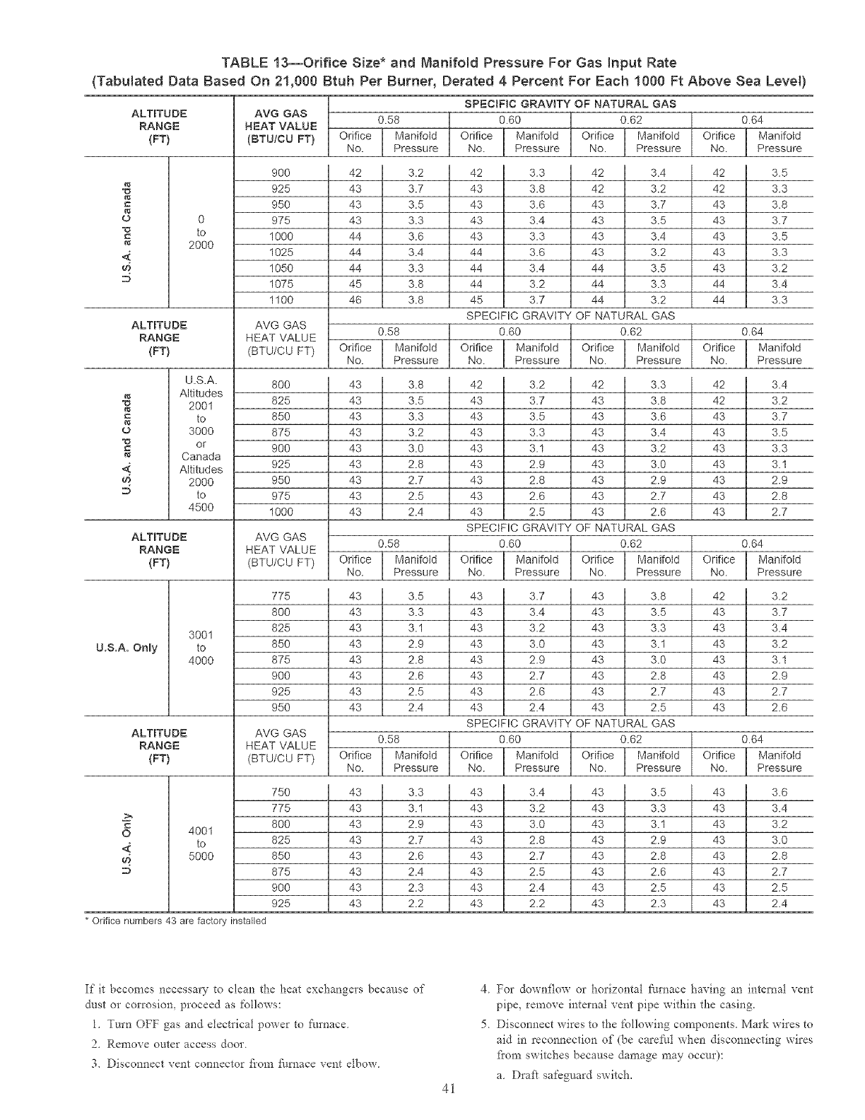
TABLE 13--Or{fice Size* and Manifold Pressure For Gas Input Rate
(Tabulated Data Based On 21,000 Btuh Per Burner, Derated 4 Percent For Each 1000 Ft Above Sea Leve0
U.S.A. Only
ALTITUDE
RANGE
{FT)
o 0
to
2000
<:
AVG GAS
NEAT VALUE
(BTU/CU FT)
9OO
925
95O
975
1000
1025
1050
1075
1100
ALTITUDE AVG GAS
RANGE HEAT VALUE
{FT) (BTU/CU FT)
U.S.A.
Altitudes
•u 2001
to
&l
o 3000
"o or
Canada
Altitudes
2000
to
4500
80O
825
85O
875
9OO
925
95O
975
1000
ALTITUDE AVG GAS
RANGE HEAT VALUE
{FT) (BTU/CU FT)
3001
to
4000
775
800
825
850
875
900
925
950
>,
O
<.
ALTITUDE AVG GAS
RANGE HEAT VALUE
(FT) (BTU/CU FT)
4001
to
5000
SPECIFIC GRAVITY OF NATURAL GAS
0.58 0.60 0.62
Orifice Manifold Orifice Manifold Orifice Manifold
No. Pressure No. Pressure No. Pressure
42 I 3.2
43 N 3.7
43 I 3.5
43 I 3.3
44- I 3.6
44 i 3.4
44 I 3.3
4b N 3.8
46 I 3.8
0.64
Orifice Manifold
No. Pressure
42 3.3 42
43 3.8 42
43 3.6 43
43 3.4 43
43 3.3 43
44 3.6 43 3.2
44 3.4 44 3.5
44 3.2 44 3.3
45 3.7 44 3.2
SPECIFIC GRAVITY OF NATURAL GAS
3.4 42 3.5
3.2 42 3.3
3.7 43 3.8
3.5 43 3.7
3.4 43 3.5
43 3.3
43 3.2
44 3.4
44 3.3
0.58 0.60 0.62
Orifice Manifold Orifice Manifold Orifice Manifotd
No. Pressure No. Pressure No. Pressure
43 I 3.8
43 N 3.5
43 I 3.3
43 I 3.2
43 I 3.0
43 N 2.8
43 I 2.7
43 I 2.5
43 I 2.4
0.64
Orifice Manifold
No. Pressure
42 3.2 42
43 3.7 43
43 3.5 43
43 3.3 43
43 3.1 43
43 2.9 43 3.0
43 2.8 43 2.9
43 2.6 43 2.7
43 2.5 43 2.6
SPECIFIC GRAVITY OF NATURAL GAS
3.3 42 3.4
3.8 42 3.2
3.6 43 3.7
3.4 43 3.5
3.2 43 3.3
43 3.1
43 2.9
43 2.8
43 2.7
0.58 0.60 0.62
Orifice Manifold Orifice Manifold Orifice Manifoid
No. Pressure No. Pressure No. Pressure
43 I 3.5 43
43 I 3.3 43
43 I 3.1 43
43 I 2.9 43
43 I 2.8 43
43 I 2.6 43
43 I 2.5 43
43 I 2.4 43
0.64
Orifice ManJfotd
No. Pressure
3.7 43
3.4 43
3.2 43
3.0 43
2.9 43 3.0
2.7 43 2.8
2.6 43 2.7
2.4 43 2.5
3.8 42 3.2
3.5 43 3.7
3.3 43 3.4
3.1 43 3.2
43 3.1
43 2.9
43 2.7
43 2.6
SPECIFIC GRAVITY OF NATURAL GAS
0.58 0.60 0.62
Orifice Manifold Orifice Manifold Onrice Manifold
No. Pressure No. Pressure No. Pressure
750 43 3.3 43
775 43 3.1 43
800 43 2.9 43
825 43 2.7 43
850 43 2.6 43
875 43 2.4 43
900 43 2.3 43
925 43 2.2 43
0.64
Orifice Manifold
No. Pressure
3.4 43
3.2 43
3.0 43
2.8 43
2.7 43
2.5 43
2.4 43
2.2 43
3.5 43
3.3 43
3.1 43
2.9 43
2.8 43
2.6 43
2.5 43
2.3 43
3.6
3.4
3.2
3.0
2.8
2.7
2.5
2.4
* Orifice numbers 43 are factory installed
If it becomes necessary Go clean the heat exchangers because of
dust or corrosiom proceed as follows:
1. Turn OFF gas and electrical power to ffmaace
2. Remove outer access door.
3. Disconnect vent connector flora flul_ace vent elbow.
41
4. For downflow or horizontal furnace having an internal vent
pipe, remove internal vent pipe within the casing.
5 Disconnect wires to the following components. Mark wires to
aid in reconnection of (be caref_ul when disconnecting wires
flora switches because damage may occur):
a Draft safeguard switch.
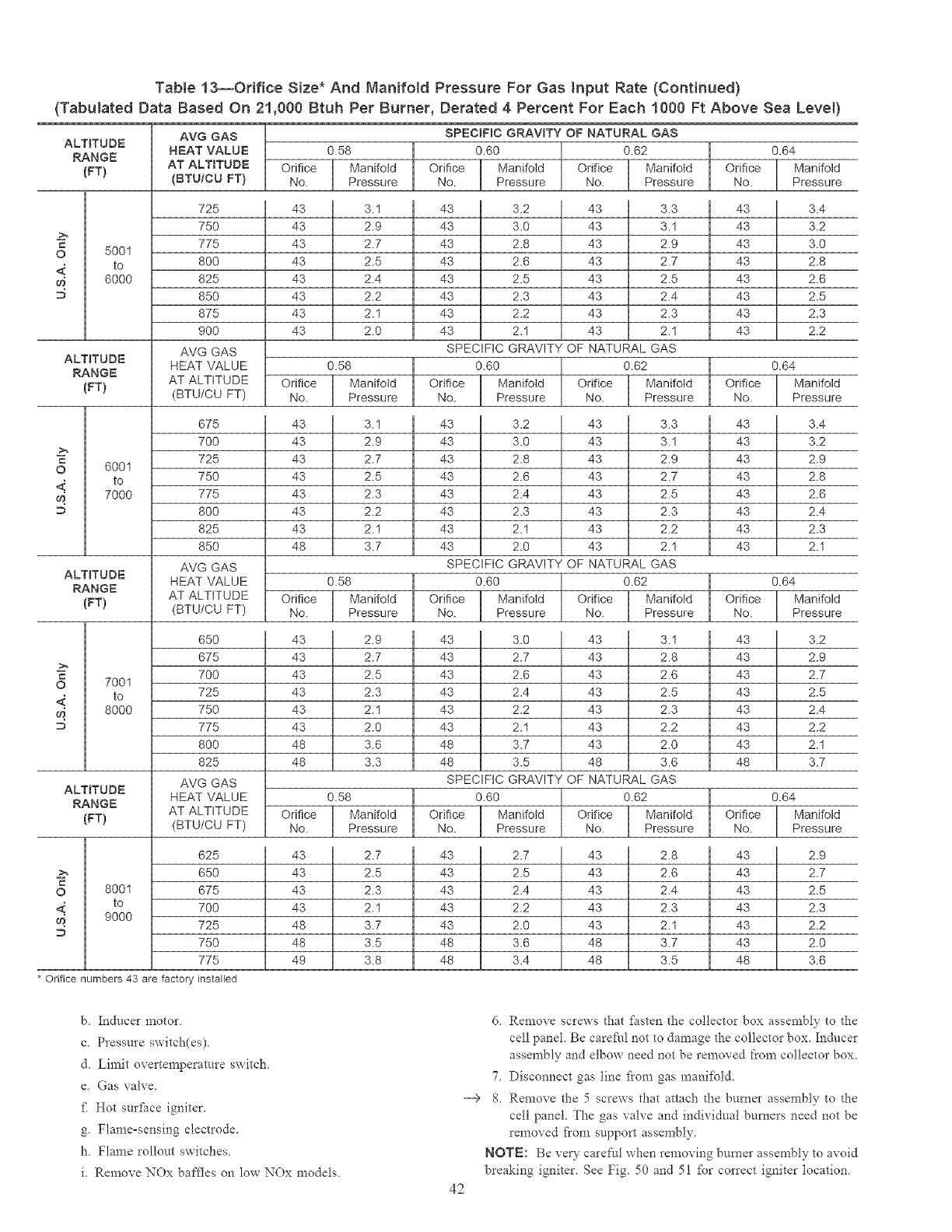
Table 13--Orifice Size* And Nanifold Pressure For Gas input Rate (Continued)
(Tabulated Data Based On 21,000 Btuh Per Burner, Derated 4 Percent For Each 1000 Ft Above Sea Level)
ALTITUDE
RANGE
(FT}
AVG GAS
NEAT VALUE
AT ALTITUDE
(BTUiCU FT} Orifice
No.
43
43
= 43
O 5001
to 43
6000 43
43
43
43
725
75O
775
800
825
850
875
900
AVG GAS
HEAT VALUE
AT ALTITUDE
(BTU/CU FT)
i Orifice
No.
43
43
43
43
43
43
43
43
Orifice
No.
675
7OO
725
75O
775
8OO
825
85O
AVG GAS
HEAT VALUE
AT ALTITUDE
(BTU/CU FT)
0.58
Manifold
Pressure
3.1
2.9
2.7
2.5
2.4
2.2
2.1
2.0
0.62
Manifotd
Pressure
43 3.3
43 3.1
43 2.9
43 2.7
43 2.5
43 2.4
43 2.3
43 2.1
NATURAL GAS
0.62
ALTITUDE
RANGE
(FT) Orifice
No.
43 43
43 43
c 43 43
O 6001
to 43 43
_ 7000 43 43
43 43
43 43
48 43
0.58
ManifoldPressure
3.1
2.9
2.7
2.5
2.3
2.2
2.1
3.7
Orifice
No.
ALTITUDE
RANGE
(FT} Orifice
No.
0.58
Manifold
Pressure
2.9
2.7
2.5
2.3
2.1
2.0
3.6
3.3
SPECIFIC GRAVITY OF NATURAL GAS
0.60
Orifice Manifold Orifice
No. Pressure No.
43 3.2
43 3.0
43 2.8
43 2.6
43 2.5
43 2.3
43 2.2
43 2.1
SPECIFIC GRAVITY OF
0.60
Orifice [ Manifold Odfice [ ManifotdNo. Pressure No. Pressure
43 3.2 43 3.3
43 3.0 43 3.1
43 2.8 43 2.9
43 2.6 43 2.7
43 2.4 43 2.5
43 2.3 43 2.3
43 2.1 43 2.2
43 2.0 43 2.1
SPECIFIC GRAVITY OF NATURAL GAS
0.60 0.62
Orifice Manifold Orifice Manifold
No. Pressure No. Pressure
43 3.0 43 3.1
43 2.7 43 2.8
43 2.6 43 2.6
43 2.4 43 2.5
43 2.2 43 2.3
43 2.1 43 2.2
48 3.7 43 2.0
48 3.5 48 3.6
SPECIFIC GRAVITY OF NATURAL GAS
0.60 0.62
43 43
43 43
c 43 43
O 7001
to 43 43
8000 43 43
43 43
48 43
48 48
Orifice [ ManifoldNo. Pressure
Orifice
No.
650
675
700
725
750
775
80O
825
AVG GAS
HEAT VALUE
AT ALTITUDE
(BTU/CU FT) l ManifoldPressure
2.8
2.6
2.4
2.3
2.1
3.7
3.5
ALTITUDE
RANGE
(FT} Orifice
No.
Orifice
No.
0.58
ManifoldPressure
2.7
2.5
2.3
2.1
3.7
3.5
3.8
625 43 43 2.7 43 43
650 43 43 2.5 43 43
c
O 8001 675 43 43 2.4 43 43
to 700 43 43 2.2 43 43
' 9000 725 48 43 2.0 43 43
750 48 48 3.6 48 43
775 49 48 3.4 48 48
0.64
Manifold
Pressure
3.4
3.2
3.0
2.8
2.6
2.5
2.3
2.2
0.64
ManifoldPressure
3.4
3.2
2.9
2.8
2.6
2.4
2.3
2.1
0.64
Manifold
Pressure
3.2
2.9
2.7
2.5
2.4
2.2
2.1
3.7
0.64
ManifoldPressure
2.9
2.7
2.5
2.3
2.2
2.0
3.6
* Orifice numbers 43 are factory installed
b, Inducer motor
c, Pressure switch(es)
d, Limit overtemperamre switch,
e. Gas valve,
fi Hot sm'fhce igniter.
g. Flame=sensing electrode,
h, Flame rollout switches
i, Remove NOx baffles on low NOx models.
42
--€
6, Remove screws that fasten the collector box assembly to d_e
cell panel, Be carefi/l not to damage the collector box, Inducer
assembly and elbow need not be removed from collector box,
7, Disconnect gas line _i'om gas mani_bld,
8, Remove the 5 screws that attach the burner assembly to the
cell panel. The gas valve and individual burners need not be
removed ['tom support assen_bly,
NOTE: Be ve W careful when removing bumm assembly to avoid
breaking igniter, See Fig, 50 and 51 _br correct igniter tocation
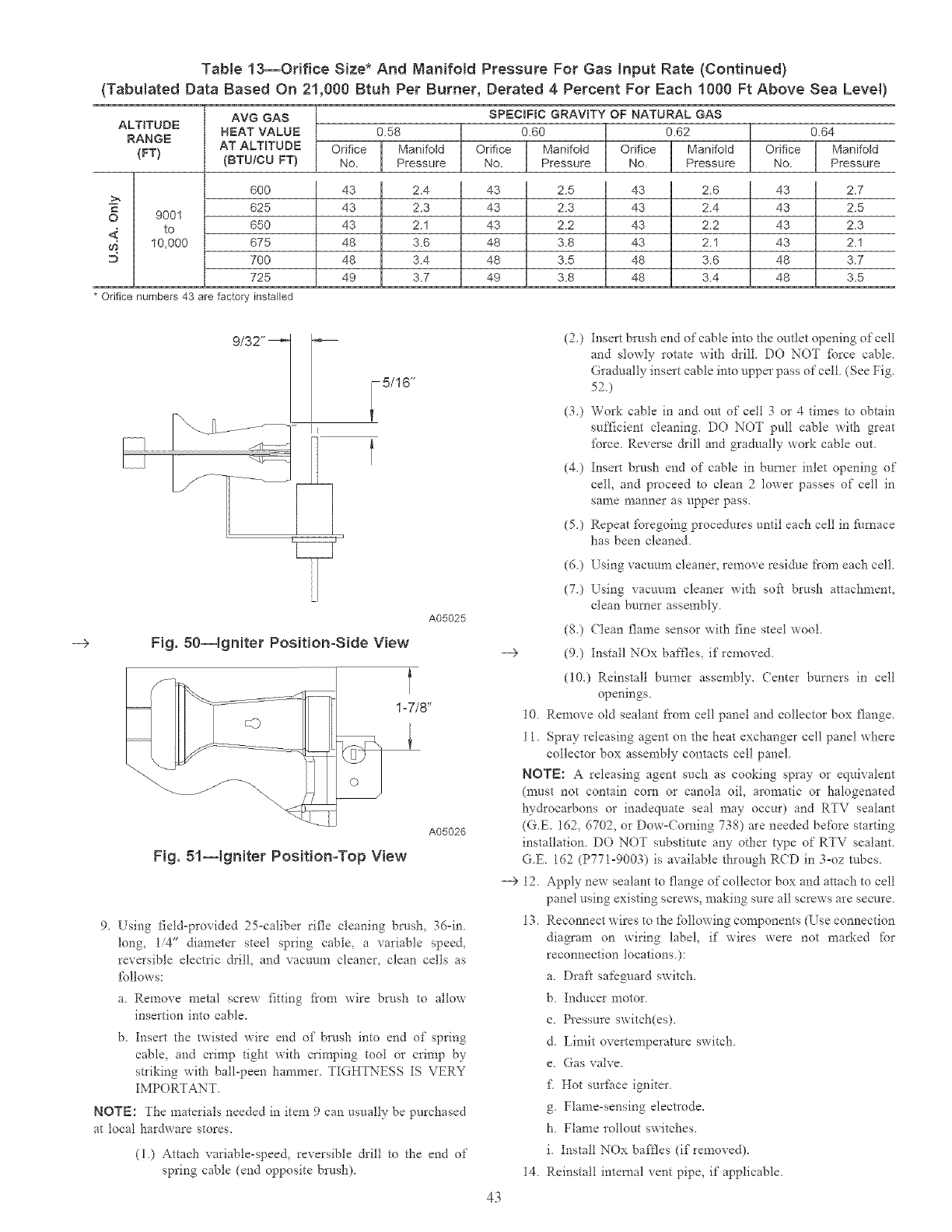
Table 13--Orifice Size* And Manifold Pressure For Gas input Rate (Continued)
(Tabulated Data Based On 21,000 Btuh Per Burner, Derated 4 Percent For Each 1000 Ft Above Sea Level)
ALTITUDE
RANGE
{FT)
AVG GAS
HEAT VALUE
AT ALTITUDE
{BTU/CU FT)
Orifice
No.
SPECIFIC
0.60
Orifice
No.
0.58
l ManifoldPressure
2.4
2.3
2.1
3.6
3.4
3.7
GRAVITY OF
Orifice
No.ManifotdPressure
2.5
2.3
2.2
3.8
3.5
3.8
NATURAL GAS
0.62
Orifice [ ManifoldNo. Pressure
43 2.6
43 2.4
43 2.2
43 2.1
48 3.6
48 3.4
600 43 43 43
625 43 43 43
O 9001
to 650 43 43 43
m_ 10,000 675 48 48 43
700 48 48 48
725 49 49 48
0.64
l ManifoldPressure
2.7
2.5
2.3
2.1
3.7
3.5
* Orifice numbers 43 are factory installed
9/32"
5/16"
A05025
Fig. 80--Igniter Position-Side View
A05026
Fig. 51--1gNter Position-Top View
9. Lsing field-provided 25-caliber rifle cleaning brush, 3d-in.
long, 1/4" diameter steel spring cable, a variable speed,
reversible electric dri!l, and vacuum cleaner, clean cells as
fol!ows:
a. Remove metal screw fitting _i'om wire brush to a!low
insertion into cable.
b. Insert the twisted wire end of brush into end of spring
cable, and crimp tight with crimping tool or crimp by
striking with ball-peon hammer. TIGHTNESS IS VERY
IMPORTANT.
NOTE: The materials needed in item 9 can usually be purchased
at local hardware stores.
(1) Attach variable-speed, reversible &il! to the end of
spring cable (end opposite brush).
(2.) Insert brush end of cable into the outlet opening of cell
and slowly rotate with &ill DO NOT force cable.
Gradual!y insert cable into upper pass of cell (See Fig.
52)
(3) Work cable in and out of cell 3 or 4 dines to obtain
sufficient cleaning. DO NOT pull cable with great
force Reverse drill and gradually work cable out.
(4) Insert brush end of cable in burner inlet opening of
col!, and proceed to clean 2lower passes of cell in
sal*le nlanner as upper pass.
(5.) Repeat foregoing procedures until each celt in Nrnace
has been cleaned.
(6) Using vacuum cleaner, remove residr/e from each cell.
(7) Using vacuum cleaner with soft brush attachment,
clean burner assernbly
(8) (?lean flame sensor with fine steel wool
--> (9) Install NOx baffles, if removed
(i0.) Reinstall burner assembly. Center burners in celt
openings.
10. Remove old sealant from cell panel and collector box flange.
11. Spray releasing agent on the heat exchanger cell panel where
collector box assembly contacts cell panel.
NOTE: A releasing agent such as cooking spray or equivalent
(must not contain corn or canola oi!, aromatic or halogenated
hydrocarbons or inadequate seal may occur) and RTV sealant
(G.E. 162, 6702, or Dow=Corning 738) are needed before starting
installation. DO NOT substitute any other type of RTV sea!ant.
G.E. 162 (P771-9003) is available through RCD in 3-oz robes.
--> 12 Apply new sealant to flange of collector box and attach to cell
panel using existing screws, making sure al! screws are secure.
13 Reconnect wires to the _bltowing components (T_se connection
diagram on wiring label, if wires were not marked _br
reconnect!on locations.):
a. Drafl safeguard switch.
b Inducer motor
c. Pressure switch(es).
d Limit overtemperature switch
e. Gas valve.
f[Hot surface igniter.
g. Flame-sensing elect*ode.
1t. Flame rollout switches.
i. Install NOx ba*tles (if removed).
14. Reinstall internal vent pipe, if applicable.
43
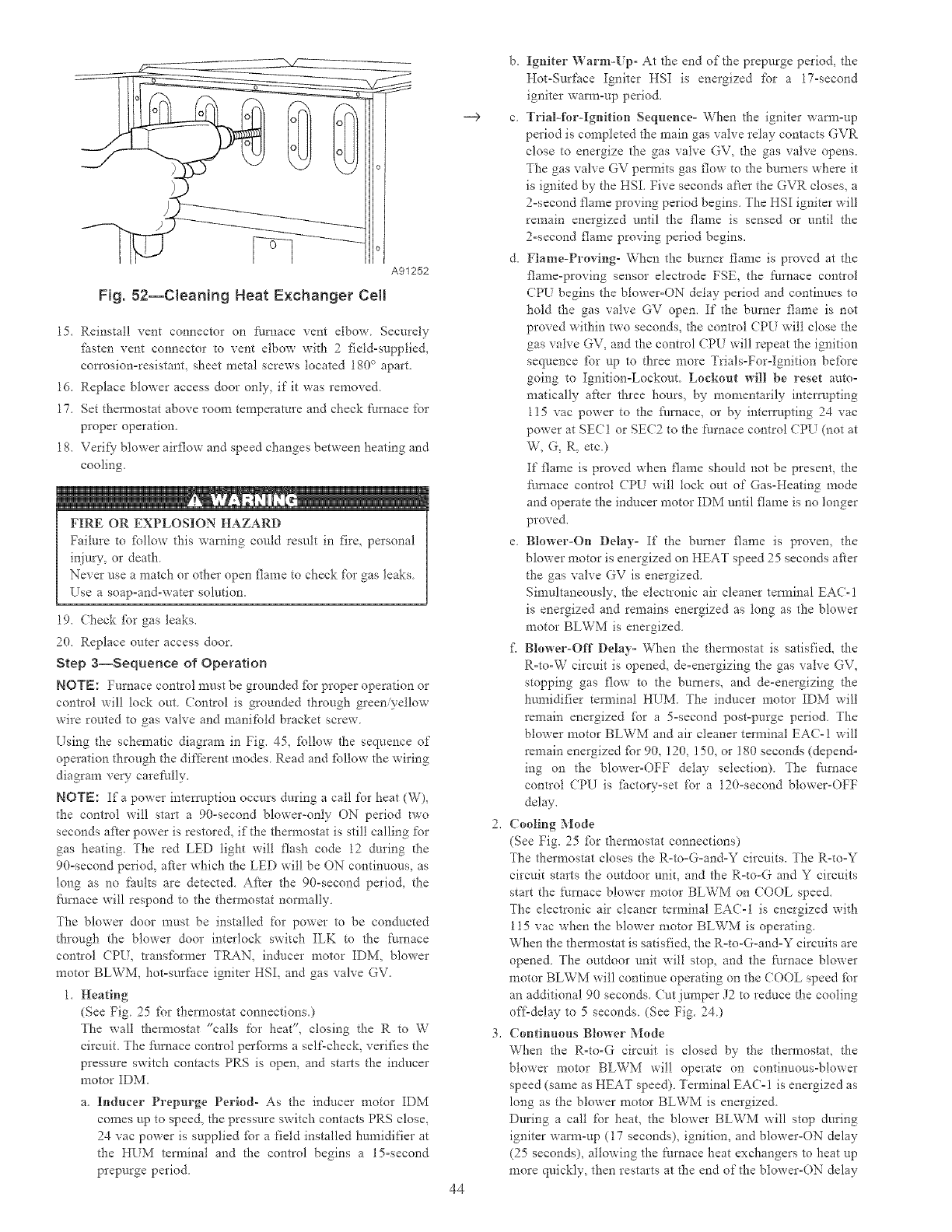
_Z
A91252
Fig. 52--CleaNng Heat Exchanger Cell
15. Reinstall vent connector on ihmace vent elbow Securely
ihsten vent connector to vent elbow with 2 field-supplied,
con'osion=resistant_ sheet metal screws located 180 c_aparL
ld. Replace blower access door only, if it was removed.
17. Set thermostat above room temperature and check [hmace for
proper operation.
18. Verify7 blower airflow and speed changes between heating and
cooling.
FIRE OR EXPLOSION HAZARD
Failure to ibllow this warning could result in fire, personal
injury, or death
Never use a match or other open flame to check for gas leaks
Use a soap=and-water solution.
19. Check %r gas leaks,
20, Replace outer access door
Step a--Sequence of Operation
NOTE: Furnace control must be grounded fbr proper operation or
control will lock out Control is grounded through green/yellow
wire routed to gas valve and manifold bracket screw
Using the schematic diagram in Fig. 45, _Pllow the sequence of
operation through the different modes. Read and ibllow the wiring
diagram very- carefully.
NOTE: If a power intemlption occurs during a call for heat (W),
the control will start a 90-second blower-only ON period two
seconds after power is restored, if the thermostat is still calling for
gas heating. The red LED light will flash code 12 during d_e
90=second period, after which the LED will be ON continuous, as
long as no faults are detected. Afier the 90-second period, the
fl/mace will respond to the thermostat normally
The blower door must be installed for power to be condacted
through the blower door interlock switch ILK to the furnace
control (PU, transibrmer TRAN, inducer motor IDM, blower
motor BLWM, hot-surface igniter HSI, and gas vah'e GV.
1, Heating
(See Fig 25 [br thermostat connections.)
The walt thermostat "calls for heat", closing the R to W
circuit. The _:hmace control perfbnns a self-check, verifies the
pressure switch contacts PRS is open, and starts the inducer
motor IDM.
a. Inducer Prepurge Period- As the inducer motor IDM
comes up to speed, the pressure switch contacts PRS close,
24 vac power is supplied ibr a field installed humidifier at
the HI_M tenninai and the control begins a 15-second
prepurge period.
--9
44
b. Igniter Warm-Up- At the end of the prepurge period, the
Hot-Surface Igniter HSI is energized ibr a 17-second
igniter warn>up period.
c Trial-for-Ignition Sequence= When the igniter warn>up
period is completed the main gas valve relay contacts GVR
close to energize the gas valve GV, the gas valve opens.
The gas valve GV permits gas flow to the burners where it
is ignited by the HSI. Five seconds aker the GVR closes, a
2-second flame proving period begins. The HSI igniter will
remain energized until the flame is sensed or until the
2-second flame proving period begins.
d. Flame-Proving- When the burner flame is proved at the
flame-proving sensor eleckode FSE, the flmaace control
CPU begins the blower=ON delay period and continues to
hold the gas valve GV open. If the burner flame is not
proved within two seconds, the control CPU will close the
gas valve GV, and the control CPU will repeat the ignition
sequence ibr up to three more Trials-For-Ignition before
going to Ignition=Lockout. Lockout will be reset auto=
matically after three hours, by momentarily interrupting
115 vac power to the flu_aace, or by intem/pting 24 vac
power at SECI or SEC2 to the [hrnace control CPU (not at
W, G, R, etc.)
[f flame is proved when flame should not be present, _he
ihmace control CPU will lock out of Gas-Heating mode
and operate the inducer motor IDM until flame is no longer
proved.
e. Blower-On Delay= If the burner flame is proven, the
blower motor is energized on HEAT speed 25 seconds after
the gas valve GV is energized.
Simultaneously, the electronic air cleaner terminal EAC-!
is energized and remains energized as tong as the blower
motor BLWM is energized.
i_ Blower-Off Delay= When the thermostat is satisfied, the
R=to-W circuit is opened, de-energizing the gas valve GV,
stopping gas flow to the buraers, and de-energizing the
humidifier terminal HUM. The inducer motor IDM will
remain energized for a 5=second post-purge period. The
blower motor BLWM and air cleaner terminal EAC-I will
remain energized ibr 90, !20, 150, or 180 seconds (depend=
ing on the blower-OFF delay selection). The furnace
control CPU is fhctory=set for a 120-second blower-OFF
delay.
Cooling Mode
(See Fig. 25 _br thermostat connections)
The thermostat closes the R-to=G=and-Y circuits. The R=to=Y
circuit starts the outdoor unit, and the R=to-G and Y circuits
start the furnace blower motor BLWM on COOL speed.
The electronic air cleaner terminal EAC-I is energized with
115 vac when the blower motor BLWM is operating.
When the thermostat is satisfied, the R=to-G-and=Y circuits are
opened. The outdoor unit will stop, and the furnace blower
motor BLWM will continue operating on the (OOL speed fbr
an additional 90 seconds. (ut jumper J2 to reduce the cooling
off'delay to 5 seconds. (See Fig. 24.)
Continuous Blower Mode
When the R=to-G circuit is closed by the thermostat, the
blower motor BLWM will operate on continuous-blower
speed (same as HEAT speed). Terminal EAC-! is energized as
long as the blower motor BLWM is energized.
During a call for heat, the blower BLWM will stop during
igniter warm-up (17 seconds), ignition, and blower-ON delay
(25 seconds), allowing the Nrnace heat exchangers to heat up
more quickly, then restarts at the end of the blower-ON delay
periodatHEATspee&
Whenthethermostat"calls%r cooling", the blower motor
BLWM will operate at COOL speed When the them_ostat is
satisfie& the blower motor BLWM will operate an additional
90 seconds on COOL speed befbre reverting back to
continuous-blower speed.
When the R°to-G circuit is opened, the blower motor BLWM
will continue operating for an additional 5 seconds, if no other
_mction requires blower motor BLWM operation
4, Heat Pump
When installed with a heat pump, the _/mace control auto°
matically changes the timing sequence to avoid long blower
off times during demand defrost cycles. When the R-to-W-
and-Y or R-to°W°and-Y-and-G circuits are energized the
fi/mace control CPU will continue to turn on the blower motor
BLWM at HEAT speed, and begin a heating cycle. The
blower motor BLWM will remain on until the end of the
prepurge period, then shut off for 24 seconds then come back
on at HEAT speed. When the W input signal disappears, the
f_/mace control begins a normal inducer post-purge period and
the blower switches to (OOL speed after a 3 second delay If
the R°to-W-and°Y°and°G signals disappear at the same time,
the blower motor BLWM will remain on for the selected
blower-OFF delay period. If the R-to°W-and-Y signals disap-
pear, leaving the G signal, the blower motor BLWM will
continue rtmning the blower motor BLWM at HEAT speed
after the selected blower-OFF delay period is completed.
Step 4--Wiring Diagrams
Refkr to Fig. 25 and 45 fbr wiring diagrams
Step 5--Troubleshooting
Refkr to the sela'ice label. (See Fig 49 Service Label.)
The Troubleshooting Guide can be a useful tool in isolating
fm'nace operation problems. Beginning with tl_e word "Start,"
answer each question and fbllow the appropriate arrow to the next
item
The Guide will help to identiI:) the problem or _i_iled component.
After replacing any component, veri_y con'ect operation sequence.
45
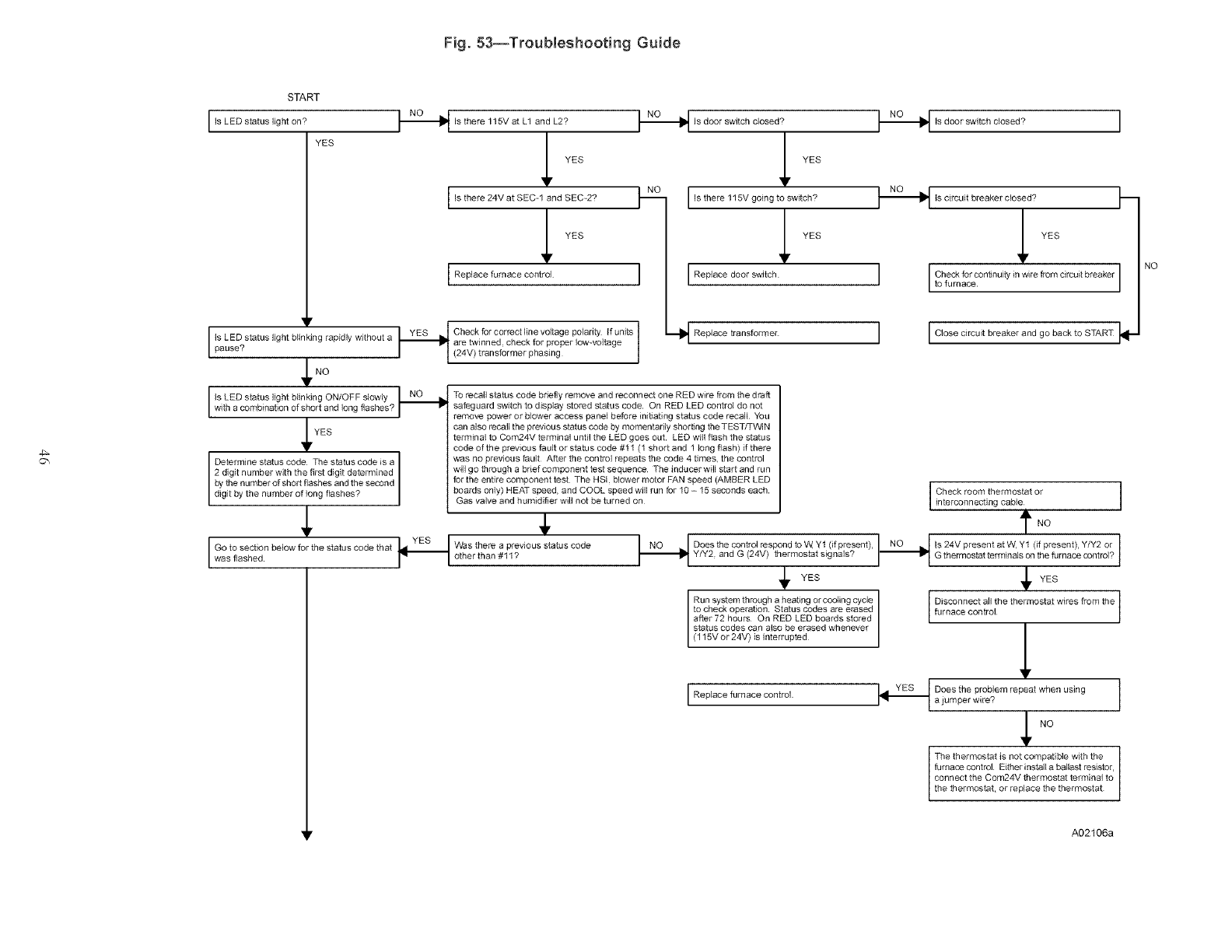
Fig. 53--Troubleshooting Guide
4_
START
is LED status on?
light
YES
Ir
is LED status light blinking rapidly without a
pause?
YES
NO NO
,_ Is there 115V at L1 and L2? _ Is door switch closed?
I Is there 24V at SEC-1 and SEC-2? _ I Is there 115V going to switch?
LBepl cefuroacecootrol ILBepl cedoorswdch
I _E_J Oh_kforcor_ectline_oltagepoI_r,_,f_oi_1 --_ RopIace#aosforme,
are twinned, check for proper low-voltage
[_1_ (24V) transfOrmer phas'ng 1
._1_ ts door switch closed?
NO
'_Is circuit breaker closed?
YES
J Check for continuity in wire from circuit breaker
to furnace
P
I I Close circuit breaker and go back to START
To recall status code briefly remove and reconnect one RED wire from the draft
safeguard switch to display stored status code On RED LED control do not
remove power or blower access panel before ini_ating status code recall You
can also recall the previous status code by momentarily shorting the TEST, q-_N
terminal to Com24V terminal until the LED goes out LED will flash the status
code of the previous fault or status code #11 (1 shorf and 1 long flash) if there
Determine status code The status code is a was no previous fault After the control repeats the code 4 t#nes, the control
2 digit number with the first digit determined will go through a brief component test sequence The inducer will start and run
by the number of short flashes and the second for the entire component test The HSl blower motor FAN speed (AMBER LED
dig t by the number of teng flashes? boards only) HEAT speed and COOL speed will run for I0- I5 ...... ds each [ Check room thermostat or ]
Gas valve and humidifier will not be turned on interconnecting cable
$YES Was there a previous status code
wasfl shedG°t°aSel fi°n below for the status code that _L,_EB Iother than #11? INO .I Does the control respond to W Y1 (if present), I NO _1 Is 24V present at W, Y1 (if present), YIY2 or I
I I I I
Y/Y2, and G (24V) th ....... tat signals? I'_1_ G thermostat terminals on tbefu ......... trst? I
i i I/ t
$ ES
Run system through a heating or cooling cycle Disconnect all the thermostat wires from the 1
to check operation Status codes are erased furnace control
I
Iafter 72 hours On RED LED boards stored
(115V or 24V) is interrupted
status codes can also be erased whenever /
YES Does the problem repeat when using
I Replace f........... trol _-E.q a jum pot wire ? 1
L The thermostat is not compatible with the
furnace control Either install a ballast resistor,
connect the Com24V thermostat terminal to
the thermostat, or replace the thermostat
NO
A02106a
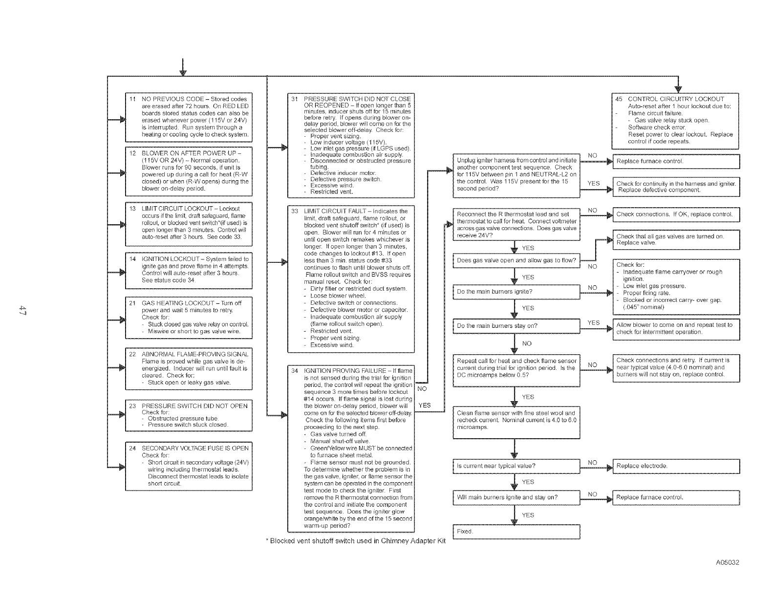
NOPREVIOUSCODE-Storedcodes
areerasedatter72hoursOnREDLED
boardsstoredstatuscodescanalsobe
erasedwheneverpower(115Vor24V)
isinterruptedRunsystemthrougha
heatingorcoolingcycletochecksystem
BLOWERONAFTERPOWERUP-
(115VOR24V)-No_mal operation.
Blower runs for 90 seconds, if unit s
powered up during a cali for heat (R-W
c_osed) or when (R-W opens) during the
Mower omdelay per od.
LIMIT CIRCUIT LOCKOUT - Lockout
occurs if the limt. draft sateguard, flame
rollout, or blocked vent switch*(it used) is
open longer than 3 minutes. Control will
auto reset atter 3 hours See code 33
IGNITION LOCKOUT- System fai_ed to
ignite gas and prove flame in 4 attempts
Control will auto-reset after 3 hours
See status code 34
1
GAS HEATING LOCKOUT - Turn off |
/
power and wait 5 minutes to retry |
Check for: t
Stuck closed gas valve relay on con_ol
Miswire or short to gas valve wi e J
1
ABNORMAL FLAME-PROVING SIGNAL |
t
Flame is proved while gas vane s de-
energized Inducer wil! run untl faut is
cleared Check for:
- Stuck open or leaky' gas valve
t
PRESSURE SWITCH DID NOT OPEN /
Check tot: 1
- Obstructed pressure tube
- Pressure switch stuck closed
1
SECONDARY VOLTAGE FUSE IS OPEN
Check for:
- Short c4rcuit in secondary vo!tage (24V) _
wirng fllcluding thermostat leads |
D scon_lect thermostat leads to isolate !
short circuit
31 PRESSURE SWITCH DID NOT CLOSE
before retry If opens durng b[cwer on-
de_ay period, b_ower wH come on for the
selected blower off-delay Check for:
- Proper vent szing.
- Low inducer voltage (115V).
-Low inlet gas pressure (it LGPS used)
-Inadequate combuston air supply
- Disconnected or obstructed pressure
tubing
- Defective inducer motor
- Defective pressure switch
- Excessve wind.
- Restricted vent.
33 LIM IT CIRCUIT FAULT - Ind cares the
limit, draft sateguard, flame to,lout, or
blocked vent shutoff sw tch* (if used) is
open Blower will run tot 4 minutes or
untii open swtch remakes whichever is
onger If open longer than 3 minutes.
code changes to lockout #13 If open
less than 3 rain status code #33
continues to flash until blower shuts oft
Fame rol!out swtch and BVSS requires
manual reset Check tot:
-Dirty filter or restr cted duct system
-Loose blower wheel
-Detective swtch or connections.
-Detective b_ower motor or capacitor
-Inadequate combustion ar supply
(flame rollout switch open)
-Restricted vent
- Proper vent szing
-Excessive wnd
34 IGNITION PROVING FAILURE - F flame
is not sensed during the trial for ignition
period, the contro} will repeat the ignition
sequence 3 more times before lockout
to furnace sheet metal
Flame sensor must not be grounded
To determine whether the problem is in
the gas valve, igniter, or flame sensor the
system can be operated in the component
test mode to check the igniter First
remove the R thermostat connection from
the control and nitiate the component
test sequence Does the igniter glow
orange/wh te by the end of the 15 second
warm-up period?
i
YE_
* Blocked vent shutoff switch used in Chimney Adapter Kit
45 CONTROL CIRCUITRY LOCKOUT
Auto-reset after 1 hour lockout due to:
Flame c rcuit ta lure
- Gas valve relay stuck open
Sottware check error
Reset power to clear lockout Replace
control if code repeats
_ Unplug igniter harness from control and initiate
another component test sequence Check 1
tot 115V between pin 1 and NEUTRAL-L2 on
thecontro_ Was115Vpresenttortbe 15 YES _ I Cbeckforcontmuityinthehamessandigniter
second period? _ Replace defective component
L
_ NC_ r
Reconnect the R thermostat lead and set _..g.:.2........_ Check connections If OK. replace control
thermostat to call for heat Connect voltmeter I "
receiveaCr°ssgaS24v?Vaiveconnections. Does gas valve I _._ Check that all gas valves are turned on
.I ......... Replace valve
• YES _NO 1_
Does gas valve open and allow gas to flow?
Inadequate flame carryover or rough
YES ignit on.
Low inlet gas pressure.
Do the main burners gnite? _ Proper firng rate.
B_ocked or incorrect carp!_ over gap.
YES (.045' nominal)
I Do the main burners stay on? _ Allow blower to come on and repeat test to
check for ntermittent operation
Repeat call for heat and check flame sensor Check connections and retry. If current is
I cu rent during tr,aifor,gn,t,on pe,iod ,sthe NQ _neaNO r typica, va,ue (4 0-6 0 nominal) and
I DC microamps below 05? _ I burners wll not stay on. replace control
,_ YES
microan]ps
Is current near typical value? _ Replace electrode
YES
[ _¢v111main burners ignite and stay on? _ Replace furnace contro_
YES
[Fixed 1
A05032

Copyright 2005 Carrier Corporation 58st13sJ
Manufacturer reserves the right to discontinue, or change at any time, specifications or designs without notice and without incurring obligations.
PC 101 Catalog No See Cover Printed Jn USA Form 58ST-13SI Pg 48 5-05 Replaces: 58ST-12SI
