PBE Europe as Axell Wireless 50-0606SERIES UHF Signal Extender User Manual RECEIVER MULTICOUPLER
Axell Wireless UHF Signal Extender RECEIVER MULTICOUPLER
UserManual.wiki
>
PBE Europe as Axell Wireless
>
50 0606SERIES User Manual
manual
Navigation menu
Upload a User Manual
Namespaces
Wiki Guide
HTML
PDF
Info
Views
User Manual
Discussion / Help
Navigation
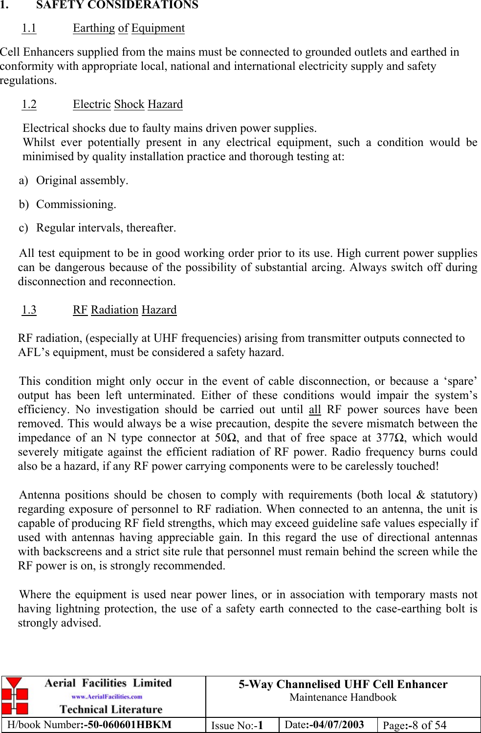
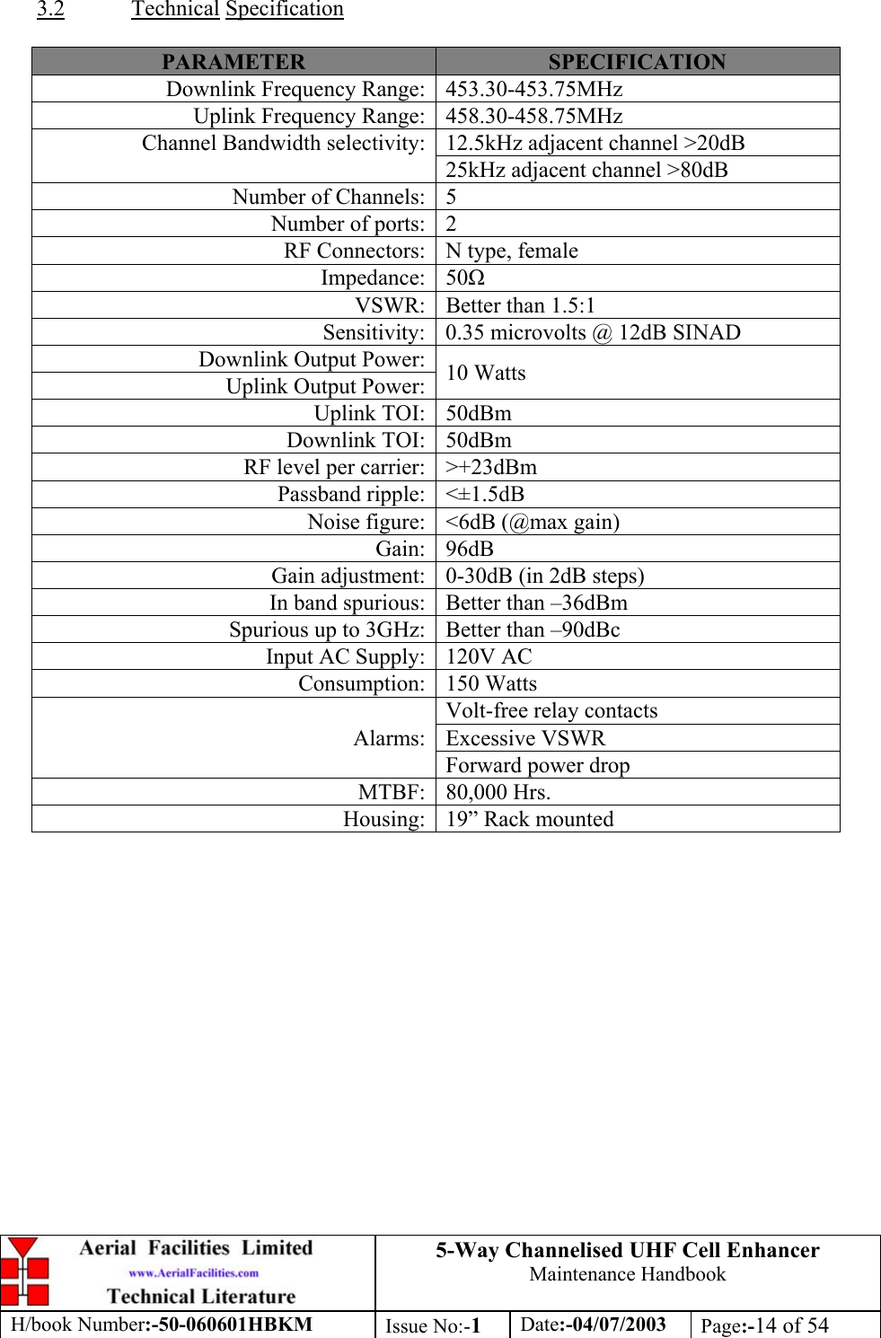
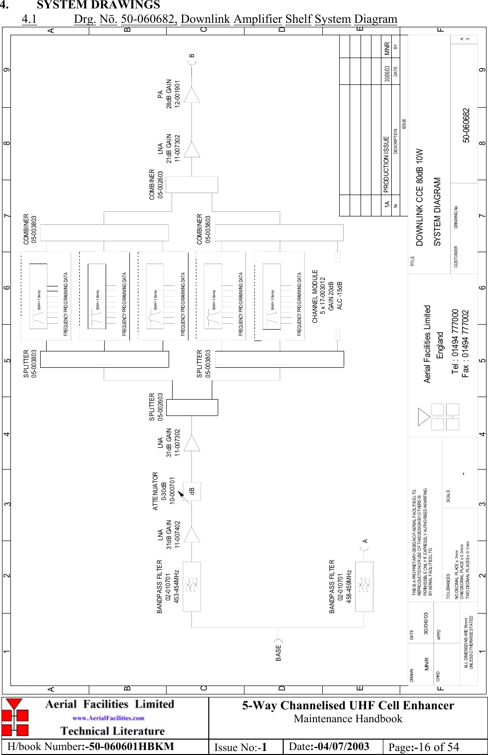
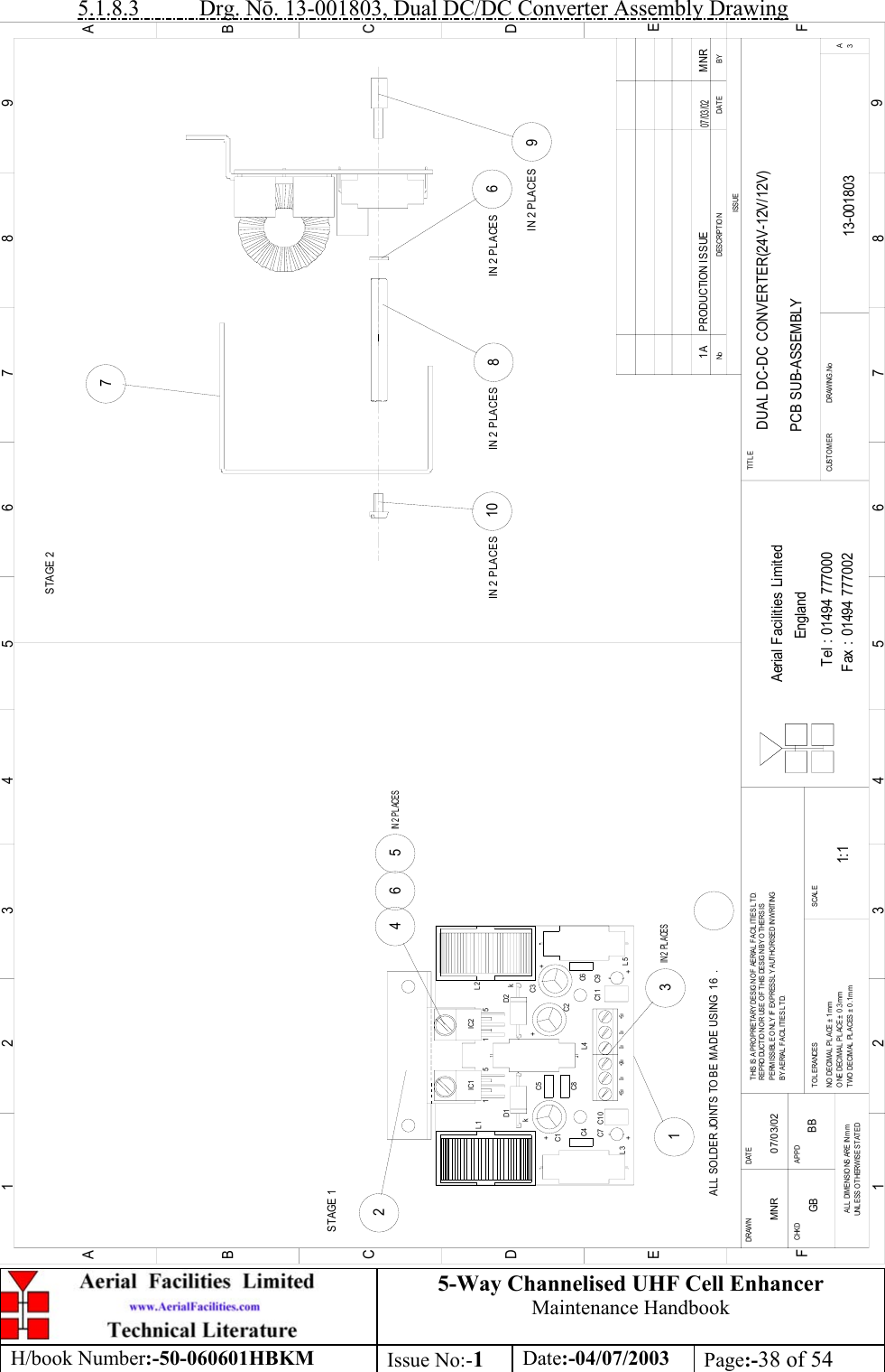
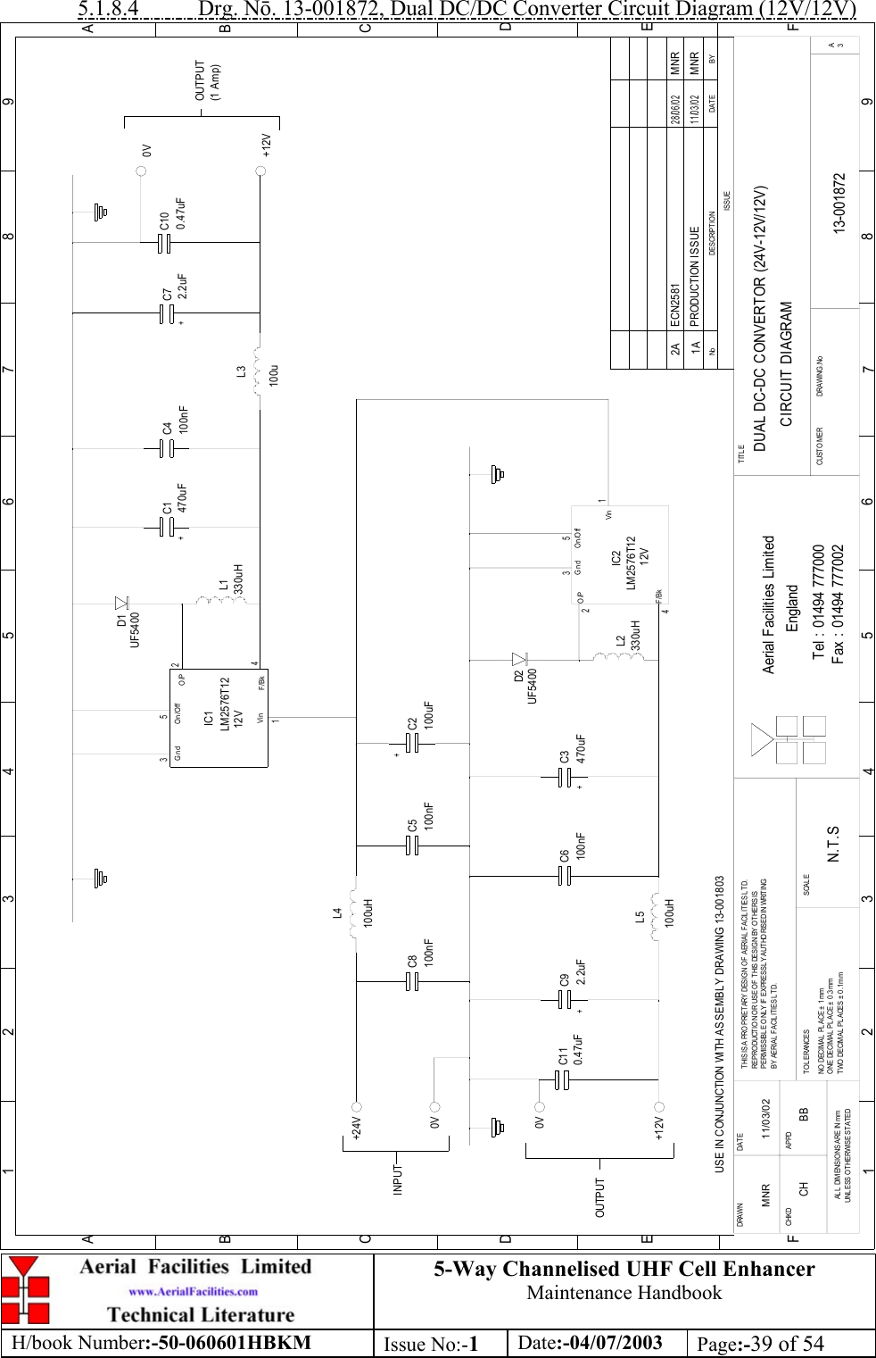
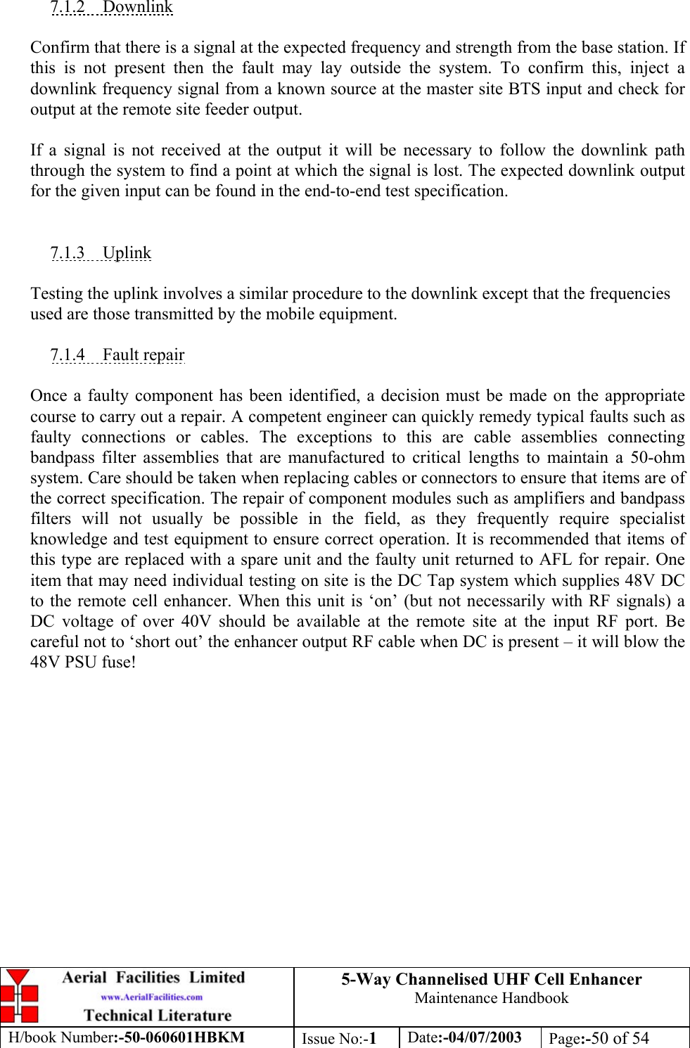
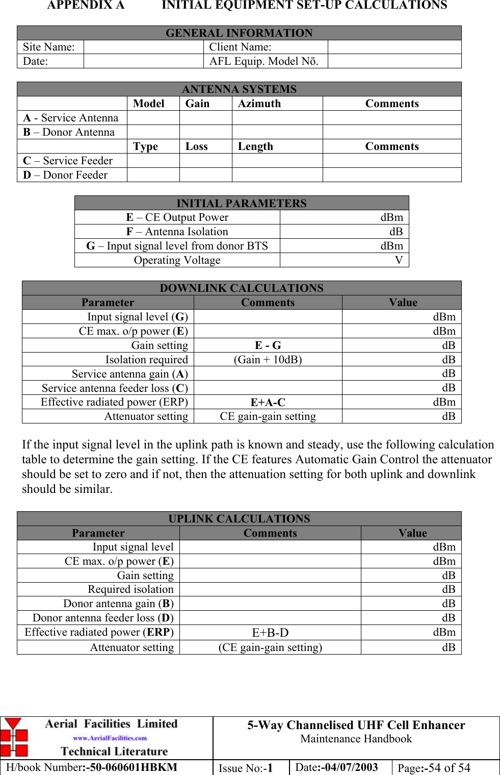
![5-Way Channelised UHF Cell EnhancerMaintenance HandbookH/book Number:-50-060601HBKM Issue No:-1Date:-04/07/2003 Page:-11 of 543. SPECIFICATION3.1 5 Channel Channelised Cell Enhancer 50-060601 Parts ListsAFL Part N.Description Qty.50-060602 D/L CCE 80dB 10W Q108330 150-060603 U/L CCE 80dB 10W Q108330 150-060604 PSU Q108330 1Modules described in the text are shown as highlighted in the parts list in the quantitycolumn. All fuses used in this equipment must be replaced with identical types asproscribed in the description column of the particular unit’s parts list.3.1.1 Downlink Channelised CE 50-060602 Parts List02-010701 5P 380MHz(V.B/W)X CPLING SMA POSTS 205-002603 UHF 3dB SPLITTER SMA 205-003803 3 WAY SPLITTER, UHF, ZINGER 410-000701 1/4W0-30dB SWITCHED ATTENUATOR 111-007302 LNA. 380-500MHz 20dB (C/W RELAY) GA 211-007402 LNA. 380-500MHz 30dB (C/W RELAY) GA 112-001901 PWR AMP.450MHz 20W GEN.ASSY 112-002201 3 STAGE AMPLIFIER ALARM BOARD 212-002220 3 STAGE ALARM PCB COVER 213-001803 DUAL DC/DC CONVERTER 24V-12V 1A 117-003012 CHAN MOD 450MHz, 15kHz (8p) BW 519-000826 2U,3U,4U 19" UNIT 400 DEEP LID 120-001602 24V RELAY BOARD 180-024420 5U CHASSIS FRONT PANEL 180-024421 5U CHASSIS 400mm DEEP 180-043320 HEATSINK 191-020004 N JACK PANEL UT-141 391-500001 POWER PLG 3 PIN PNL.MOUNT NC-X 191-510003 3 PIN R.ANGLE FREE SOC.NC-X. 191-600001 'D'TYPE 9 WAY PLUG S/B TERM 191-620001 'D' 25 WAY SOCKET S/B TERM 291-620006 'D' 25 WAY CONNECTOR SHELL 291-700017 ICD 15 WAY 0.1' CONNECTOR 492-340001 M3 x 8mm 'D'CONNECTOR SCREW LOCK 096-110001 FUSE HOLDER 20 x 5mm6.3A 196-110013 T 3.15 A ANTI SURGE FUSE 20mm 196-500005 DC INPUT FILTERS 196-600002 INSULATING BOOT SMALL 196-600003 INSULATING BOOT D.C. 197-400006 5U HANDLE [ALLOY] 2](https://usermanual.wiki/PBE-Europe-as-Axell-Wireless/50-0606SERIES/User-Guide-360948-Page-11.png)
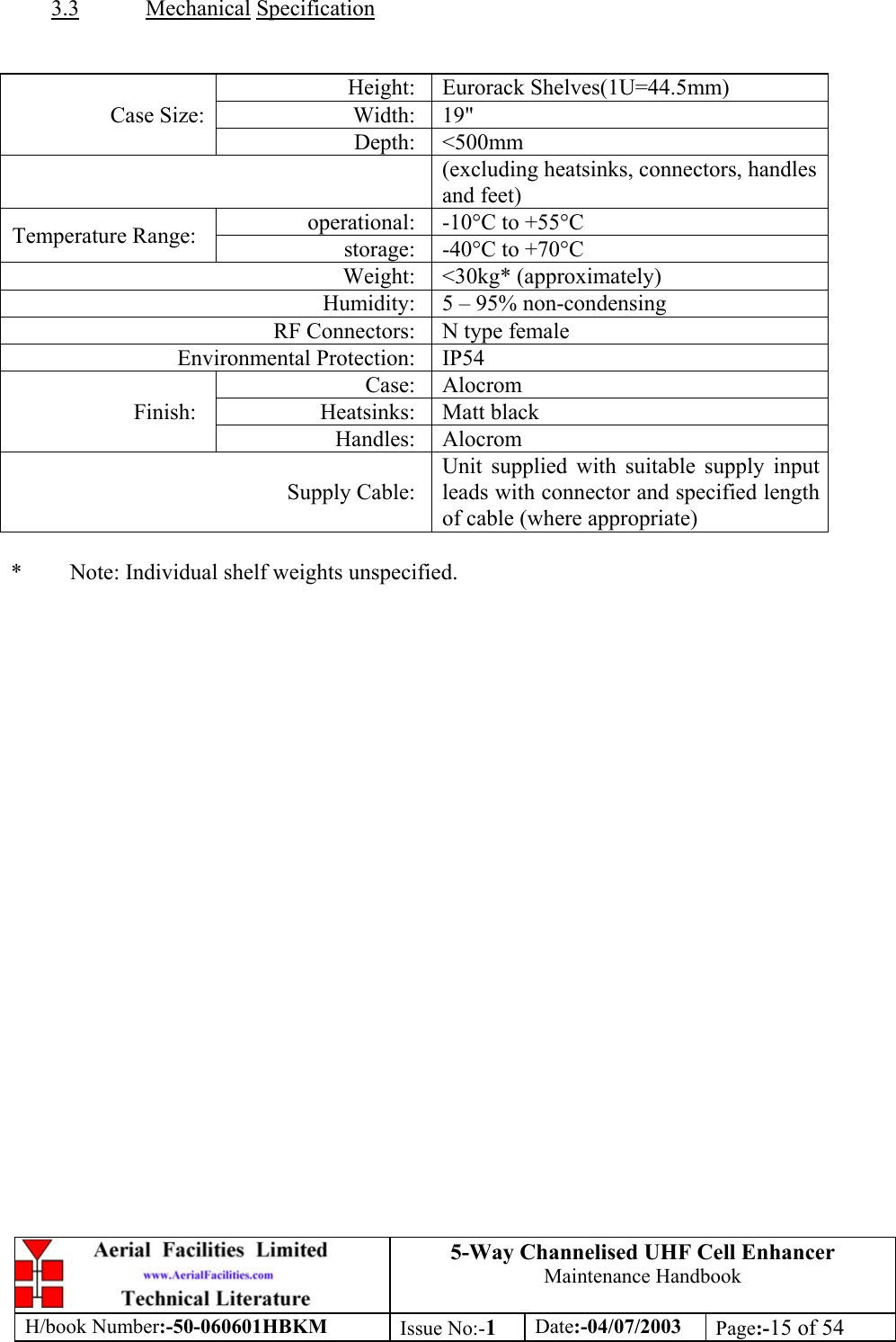
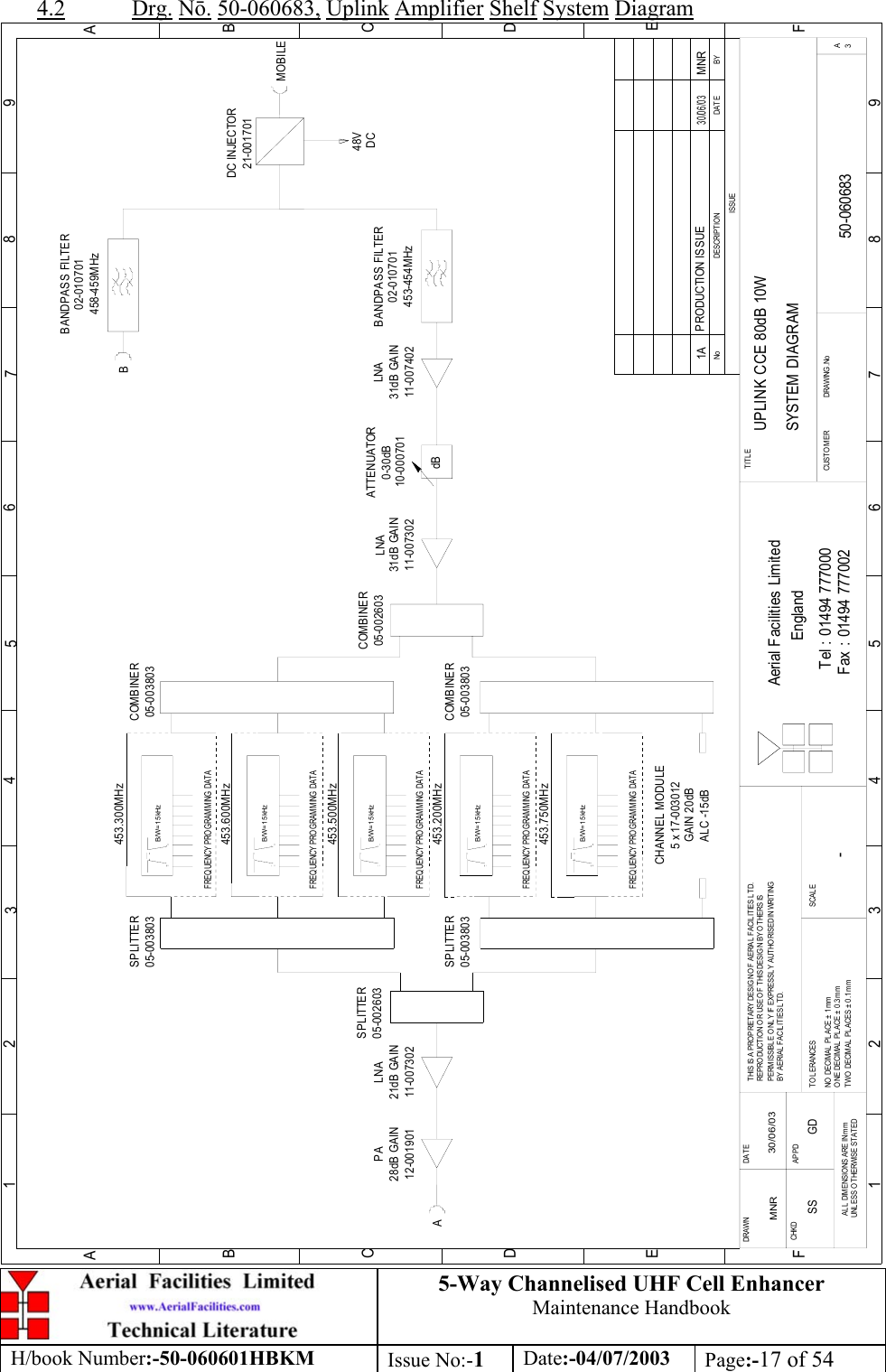
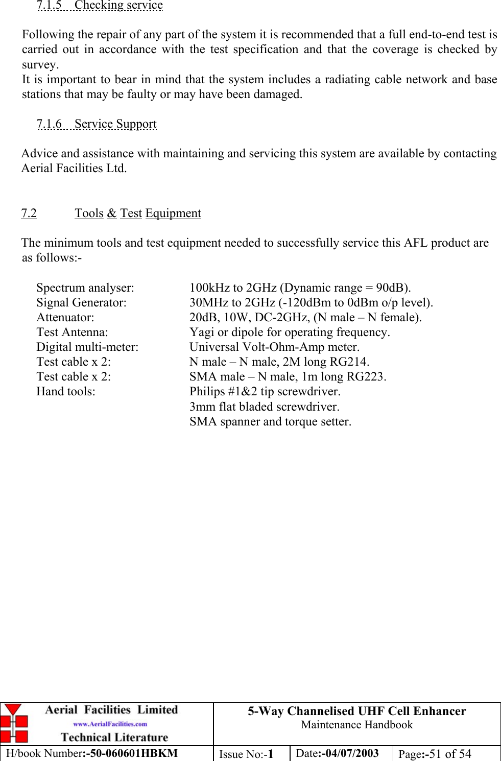
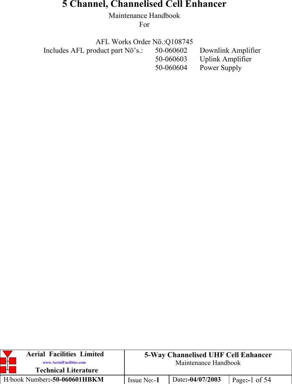
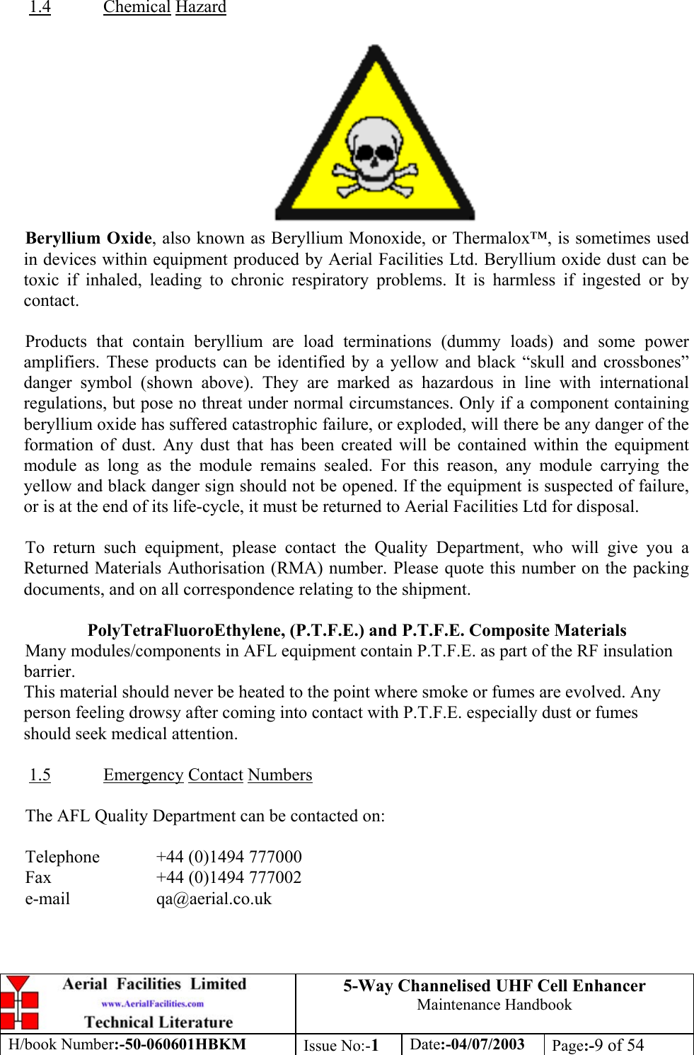
![5-Way Channelised UHF Cell EnhancerMaintenance HandbookH/book Number:-50-060601HBKM Issue No:-1Date:-04/07/2003 Page:-12 of 543.1.2 Uplink Channelised CE 50-060603 Parts ListAFL Part N.Description Qty.02-010701 5P 380MHz(V.B/W)X CPLING SMA POSTS 205-002603 UHF 3dB SPLITTER SMA 205-003803 3 WAY SPLITTER, UHF, ZINGER 410-000701 1/4W0-30dB SWITCHED ATTENUATOR 111-007302 LNA. 380-500MHz 20dB (C/W RELAY) GA 211-007402 LNA. 380-500MHz 30dB (C/W RELAY) GA 112-001901 PWR AMP.450MHz 20W GEN.ASSY 112-002201 3 STAGE AMPLIFIER ALARM BOARD 212-002220 3 STAGE ALARM PCB COVER 213-001803 DUAL DC/DC CONVERTER 24V-12V 1A 117-003012 CHAN MOD 450MHz, 15kHz (8p) BW 519-000826 2U,3U,4U 19" UNIT 400 DEEP LID 120-001602 24V RELAY BOARD 121-001701 DC TAP PT FREEPORT 180-024420 5U CHASSIS FRONT PANEL 180-024421 5U CHASSIS 400mm DEEP 180-043320 HEATSINK 191-020004 N JACK PANEL UT-141 391-500001 POWER PLG 3 PIN PNL.MOUNT NC-X 291-510003 3 PIN R.ANGLE FREE SOC.NC-X. 191-600001 'D'TYPE 9 WAY PLUG S/B TERM 191-620001 'D' 25 WAY SOCKET S/B TERM 291-620006 'D' 25 WAY CONNECTOR SHELL 291-700017 ICD 15 WAY 0.1' CONNECTOR 492-340001 M3 x 8mm 'D'CONNECTOR SCREW LOCK 096-110001 FUSE HOLDER 20 x 5mm6.3A 196-110013 T 3.15 A ANTI SURGE FUSE 20mm 196-500005 DC INPUT FILTERS 196-600002 INSULATING BOOT SMALL 196-600003 INSULATING BOOT D.C. 197-400006 5U HANDLE [ALLOY] 2](https://usermanual.wiki/PBE-Europe-as-Axell-Wireless/50-0606SERIES/User-Guide-360948-Page-12.png)
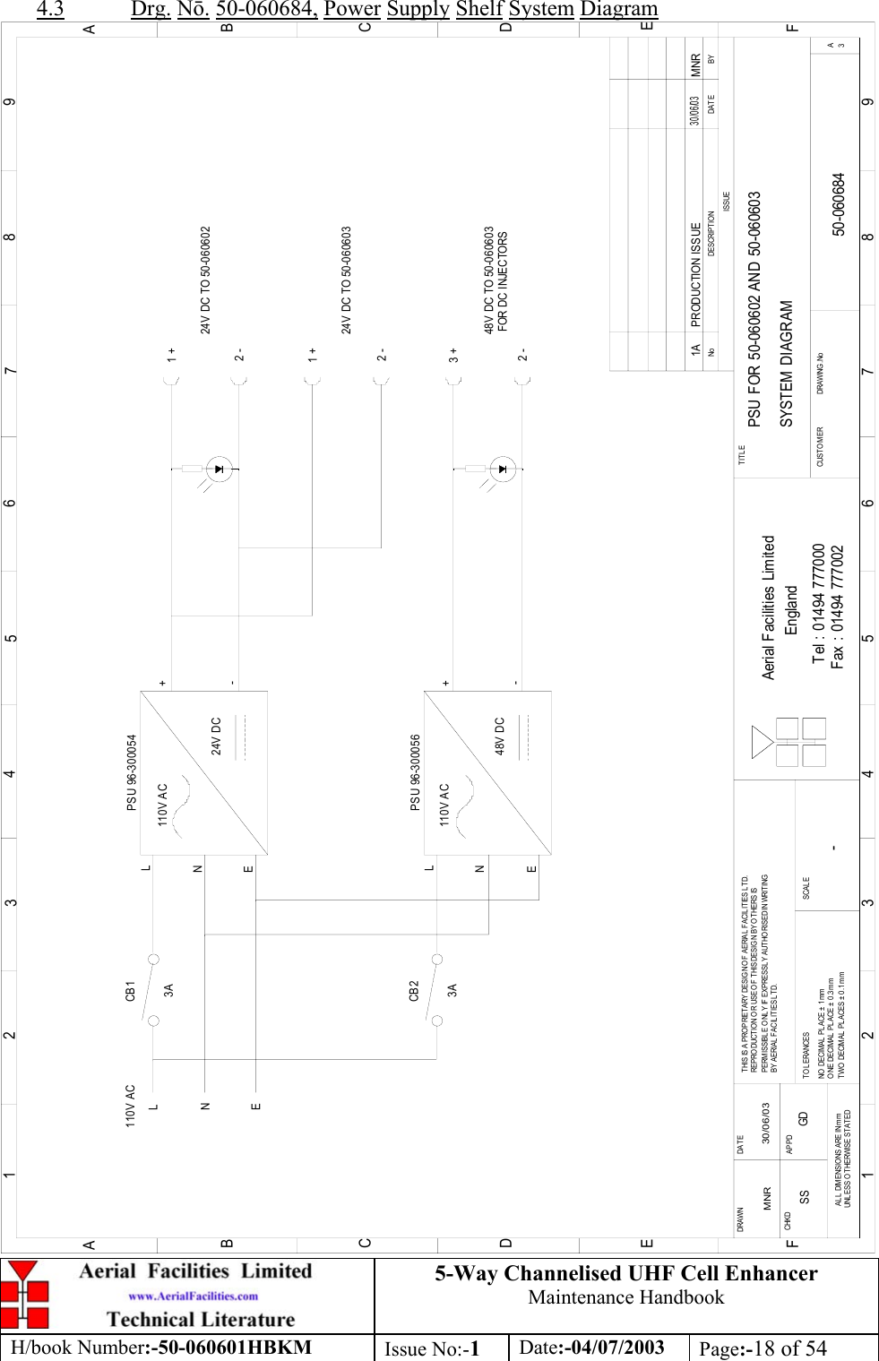
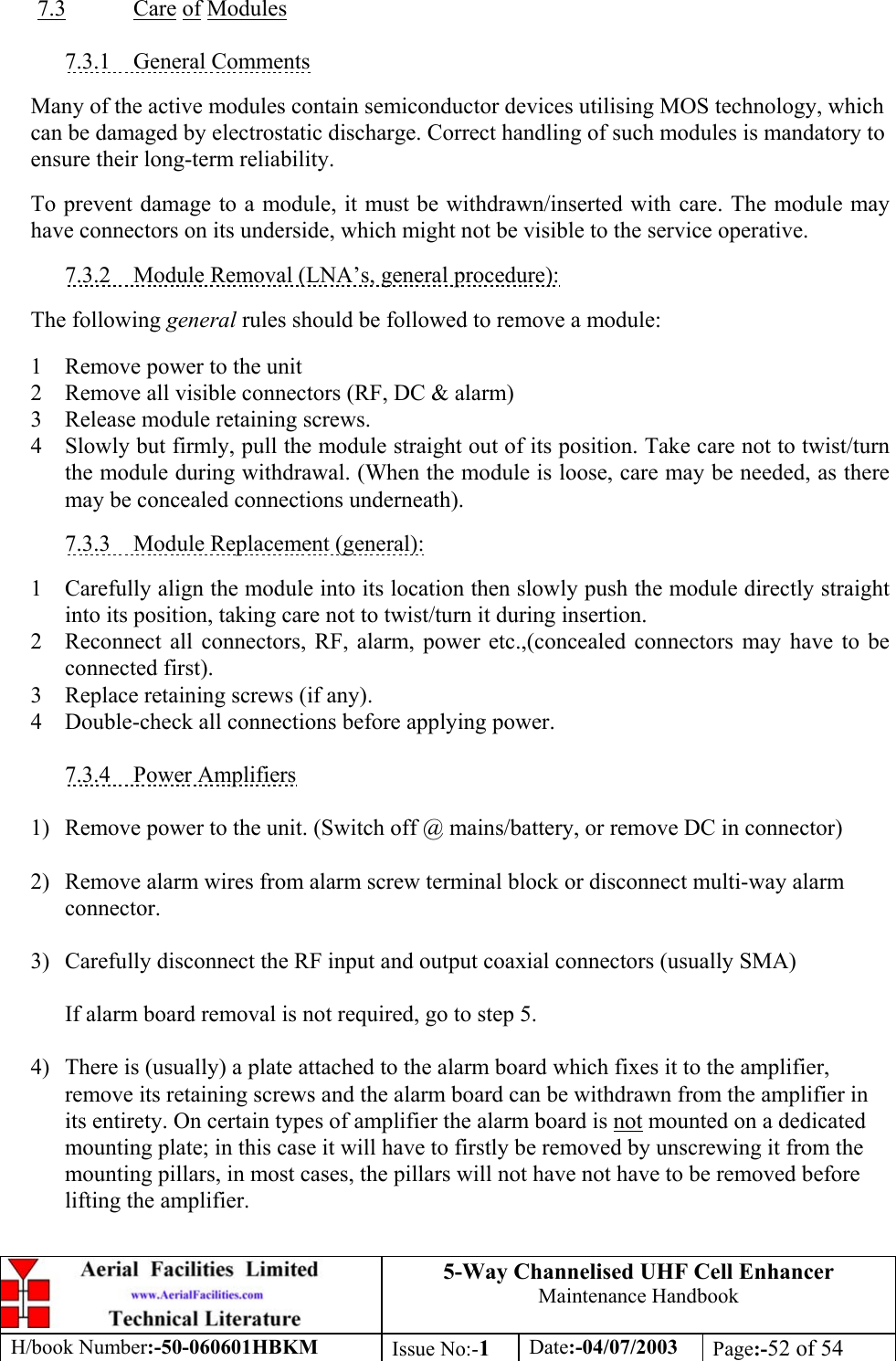
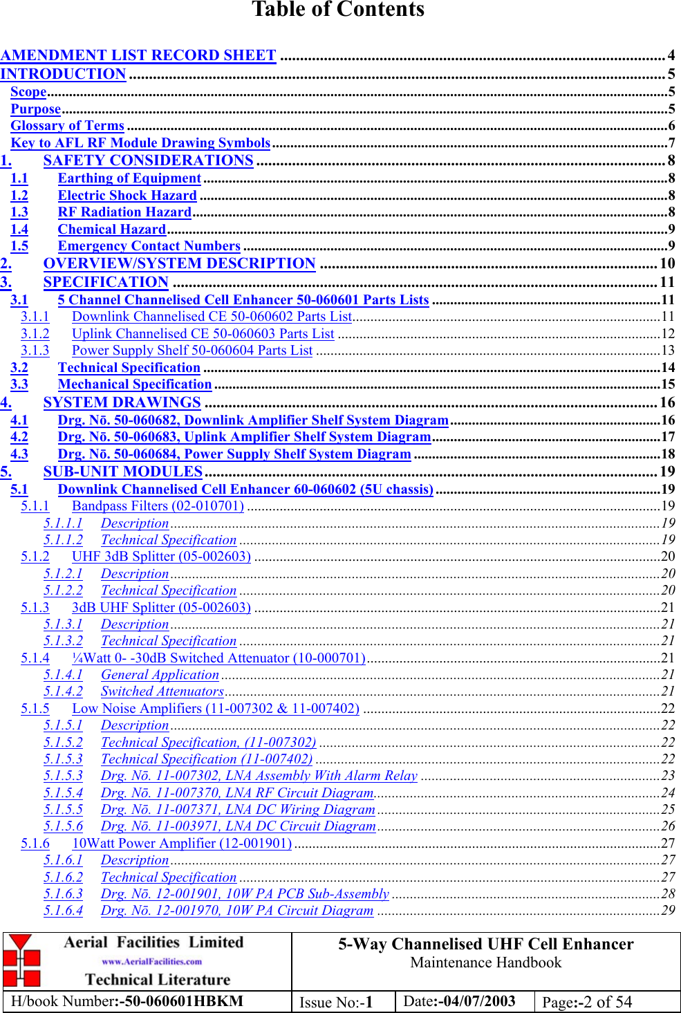
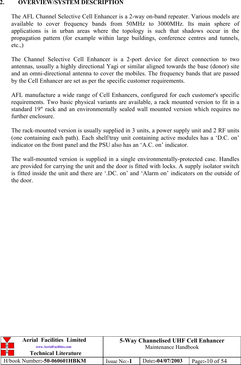
![5-Way Channelised UHF Cell EnhancerMaintenance HandbookH/book Number:-50-060601HBKM Issue No:-1Date:-04/07/2003 Page:-13 of 543.1.3 Power Supply Shelf 50-060604 Parts List19-000826 2U,3U,4U 19" UNIT 400 DEEP LID 119-001021 4U 19" UNIT 400 DEEP CHASSIS + BKT 119-001024 4U 19" UNIT FRONT PANEL FAB 120-001602 24V RELAY BOARD 180-064120 HEATSINK 4U FLATPAC 16A 10W 191-500025 3 PIN RIGHT ANGLE FREE PLUG NC-X 191-510003 3 PIN R.ANGLE FREE SOC.NC-X. 191-510004 3 PIN PNL.MOUNT SOCKET NC-X 391-520001 PWR MAINS INL FIXED/SOLD.TERMS 391-520004 POWER MAINS INL.FREE R/ANGLE 391-600001 'D'TYPE 9 WAY PLUG S/B TERM 192-340001 M3 x 8mm 'D'CONNECTOR SCREW LOCK 093-560001 VARISTOR V275LA20A 196-300054 24V 17A PSU 400W (XP BCC) 196-300056 48V 6A PSU DIN RAIL (TRACO) 196-700034 LED RED 5mm IP67 INTEGRAL RES. 24V 196-700035 LED GREEN 5mm IP67 INTEGRAL RES 24V 296-900018 AC TRIP SWITCH (5 AMP M.C.B.) 297-400002 HANDLE TYPE H6803 4U.[ALLOY] 2](https://usermanual.wiki/PBE-Europe-as-Axell-Wireless/50-0606SERIES/User-Guide-360948-Page-13.png)