PBE Europe as Axell Wireless 50-0780-VHF VHF Cell Enhancer User Manual
Axell Wireless VHF Cell Enhancer
UserManual.wiki
>
PBE Europe as Axell Wireless
>
50 0780 VHF User Manual
User manual
Navigation menu
Upload a User Manual
Namespaces
Wiki Guide
HTML
PDF
Info
Views
User Manual
Discussion / Help
Navigation
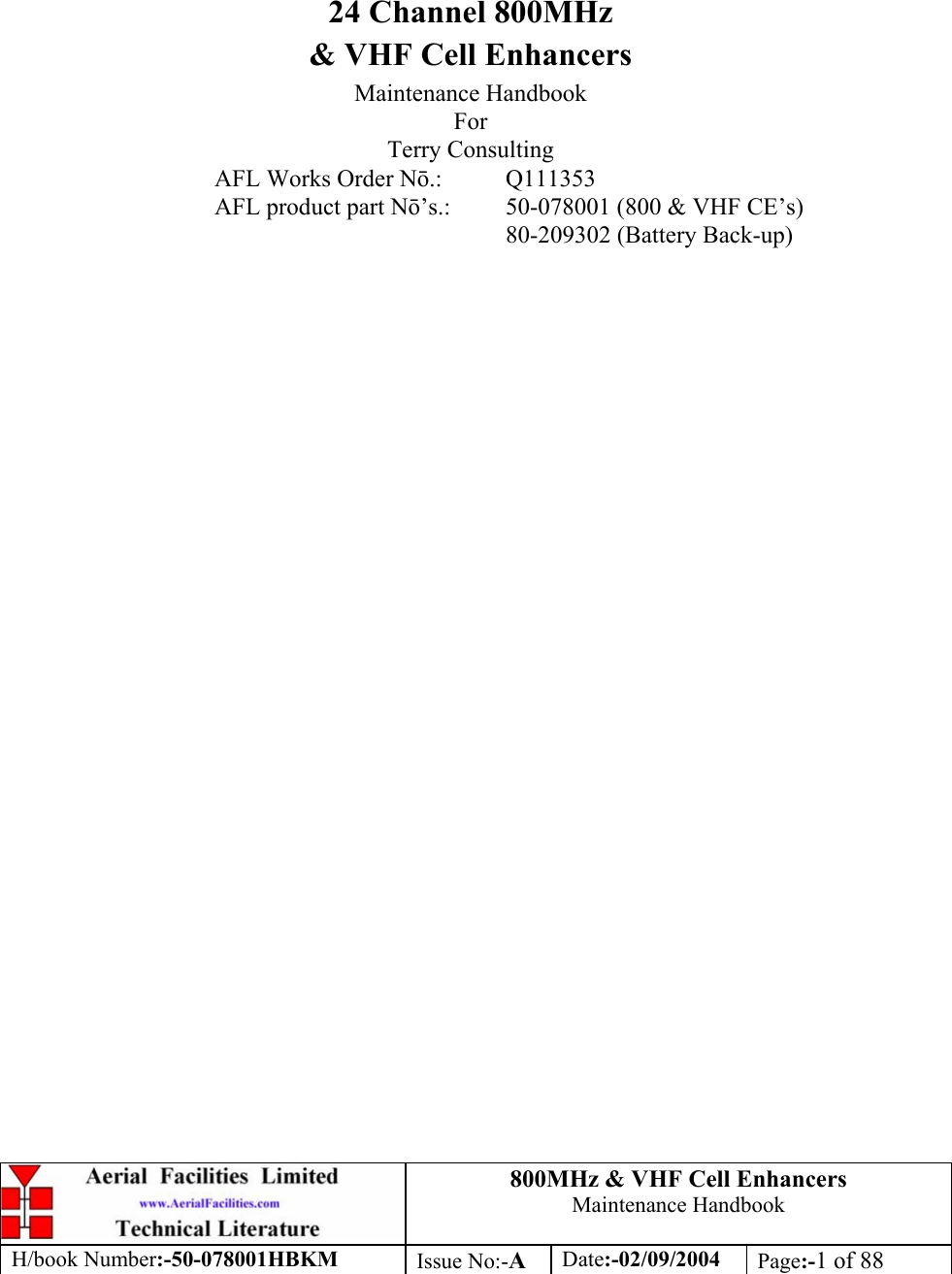
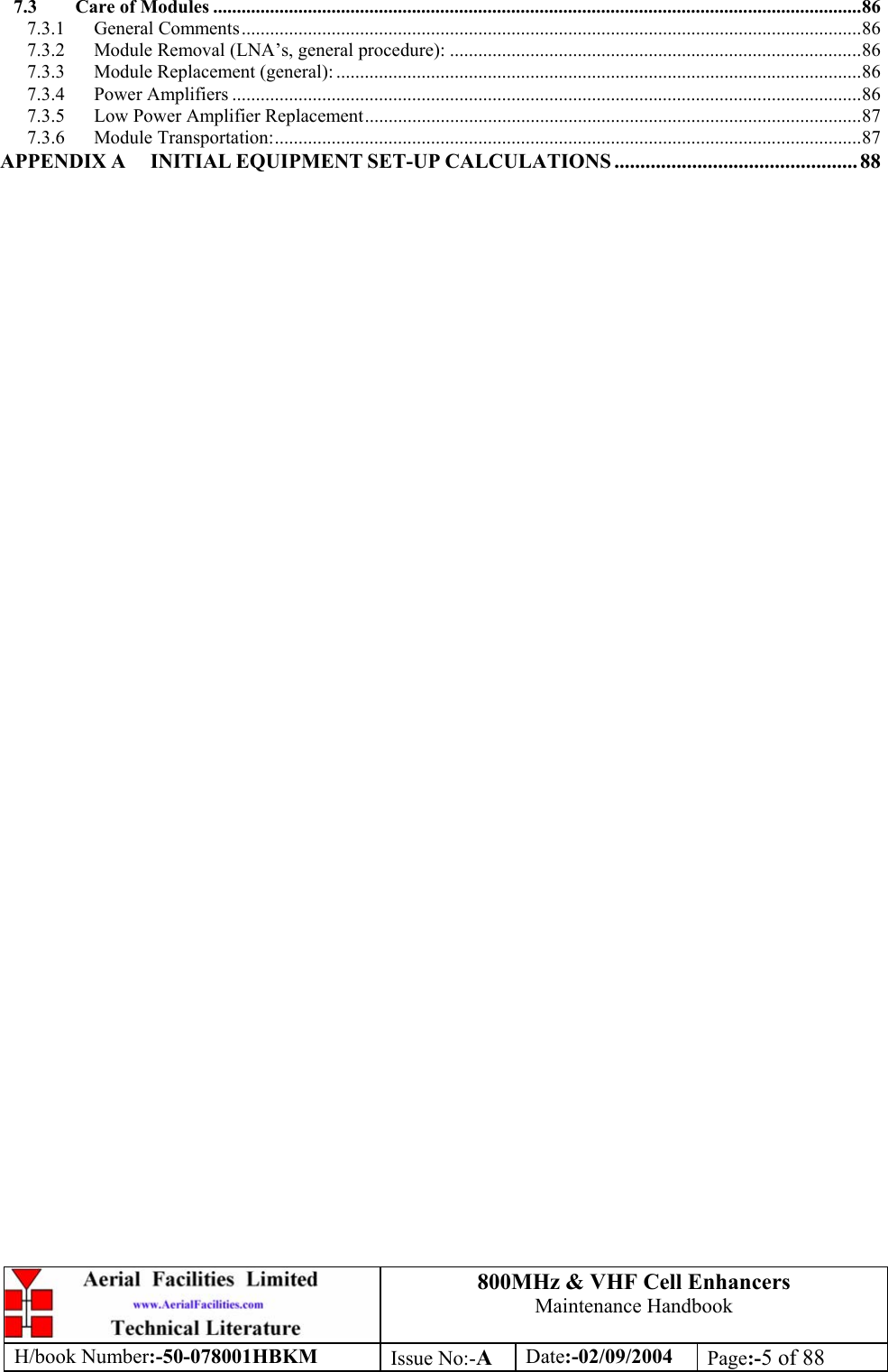
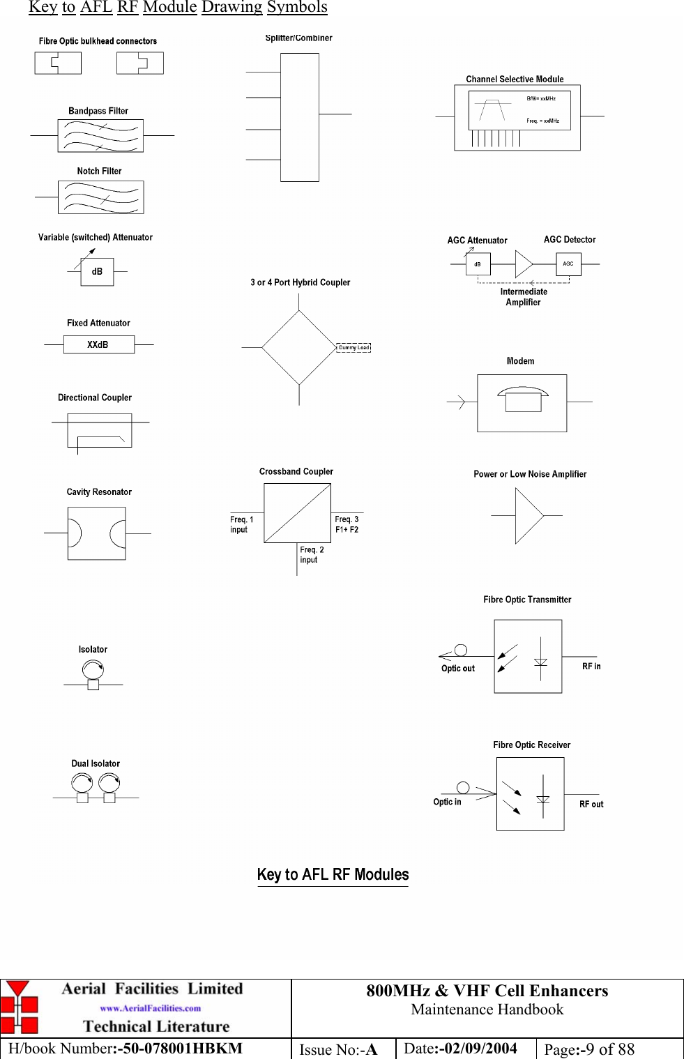
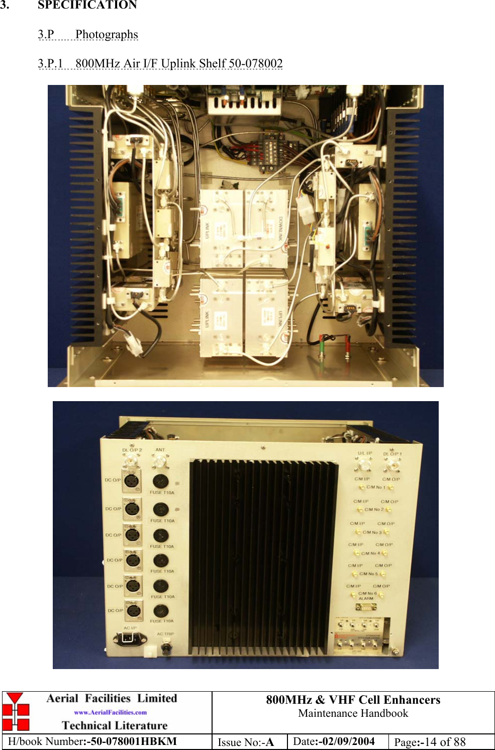


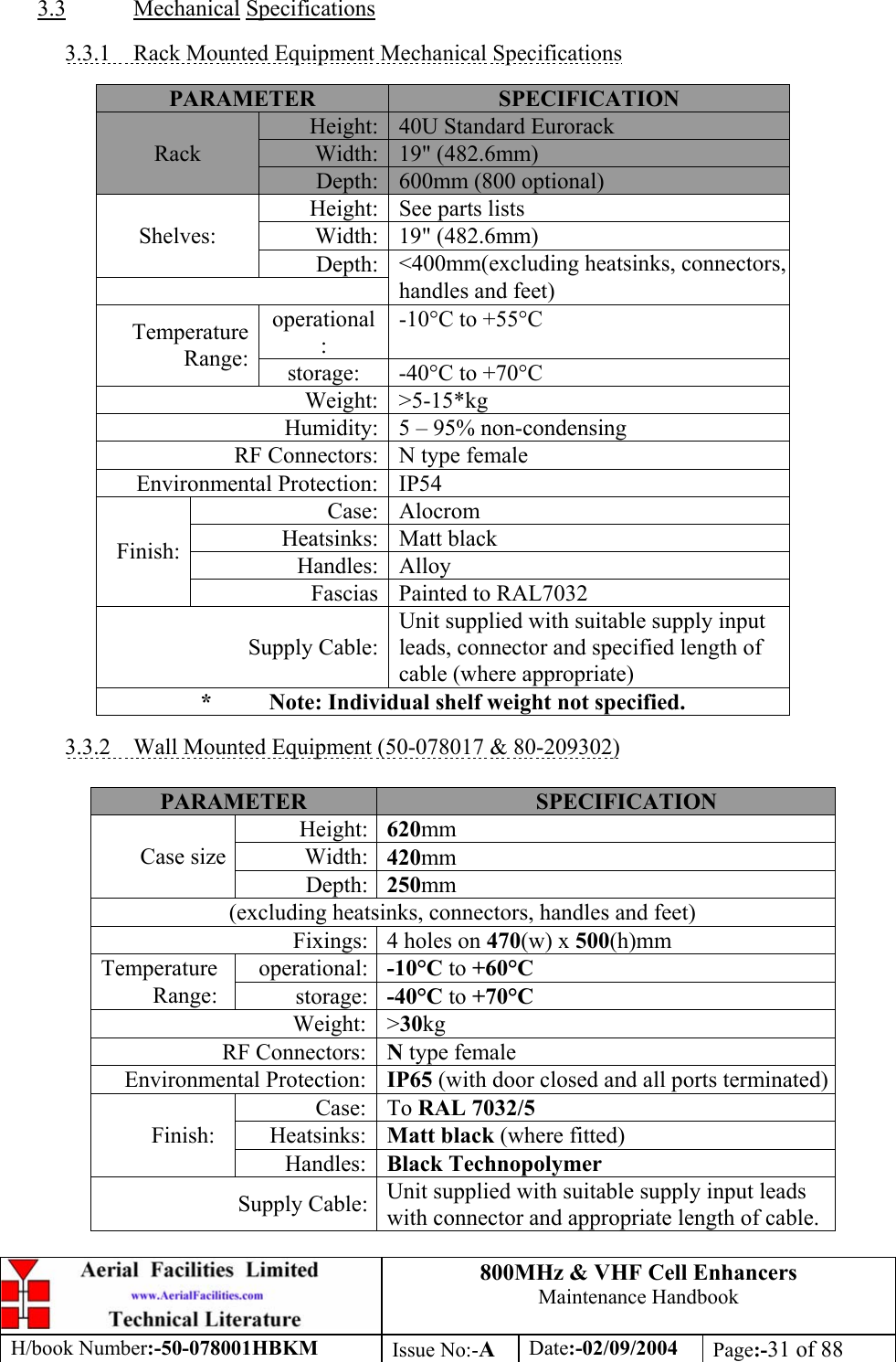
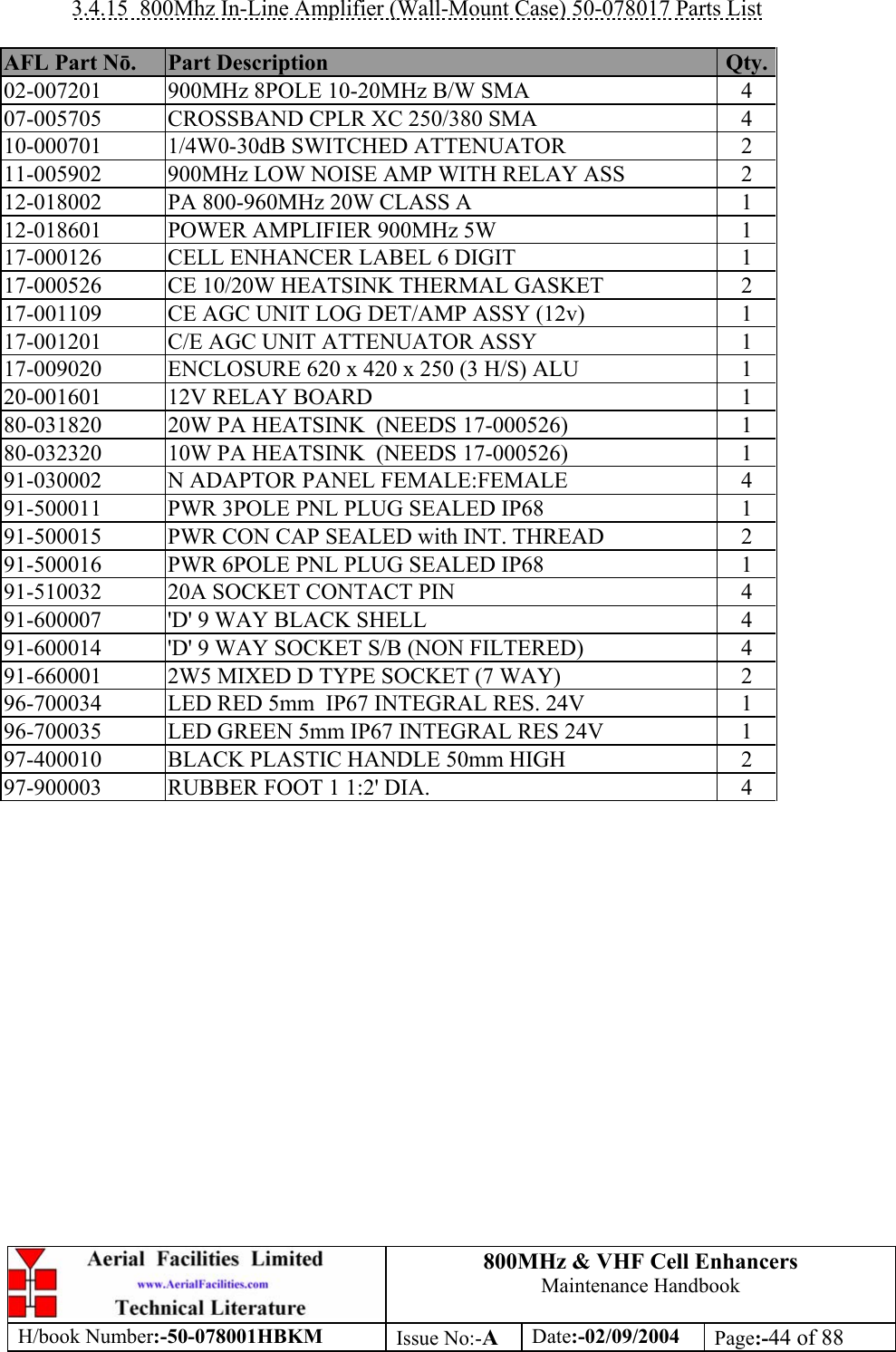
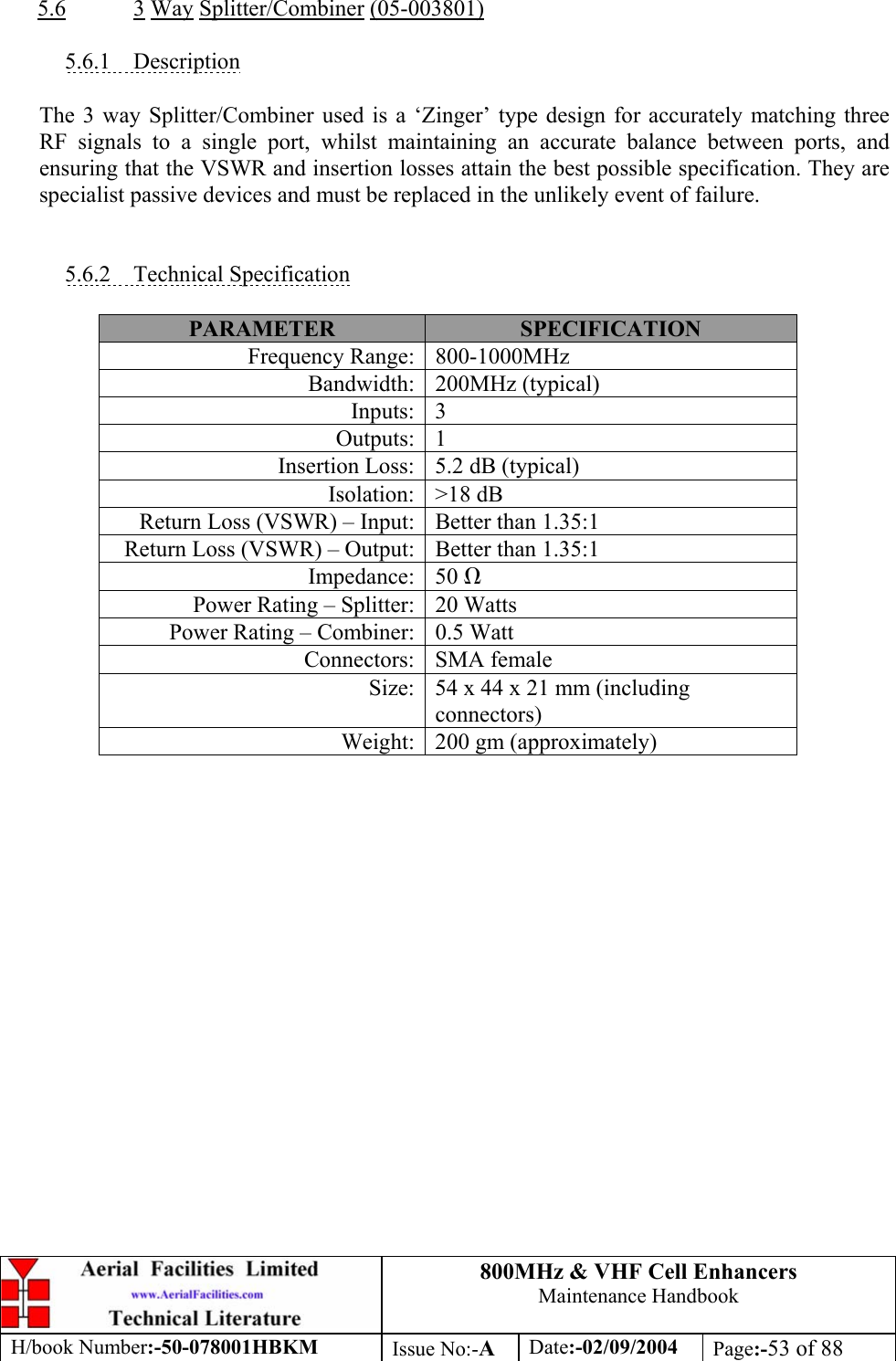
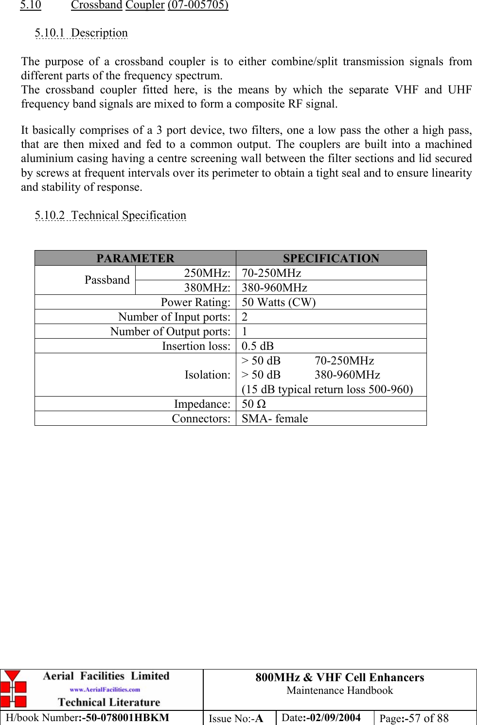
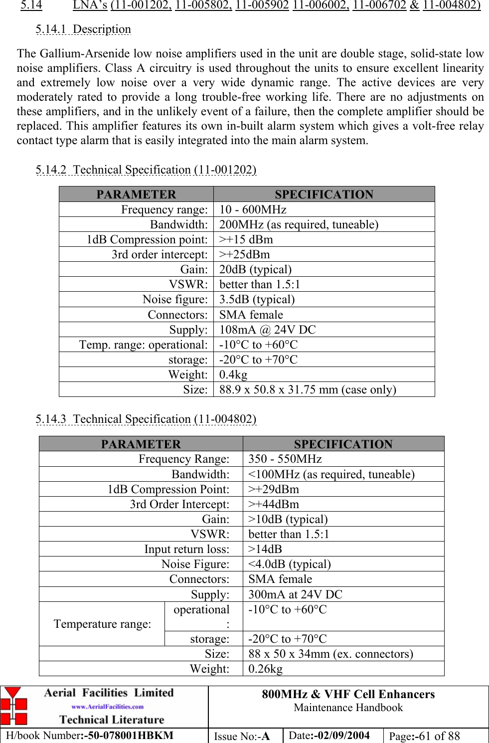
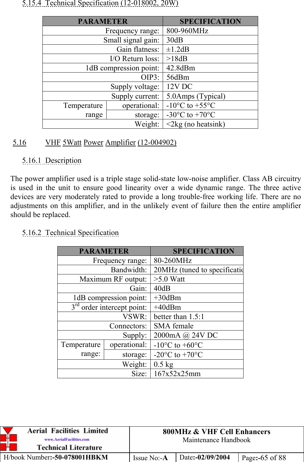
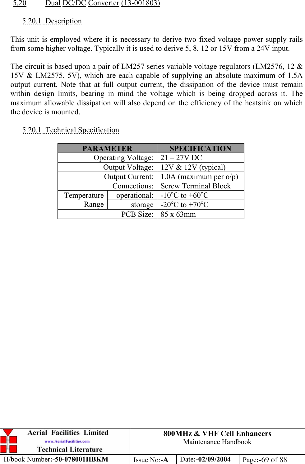
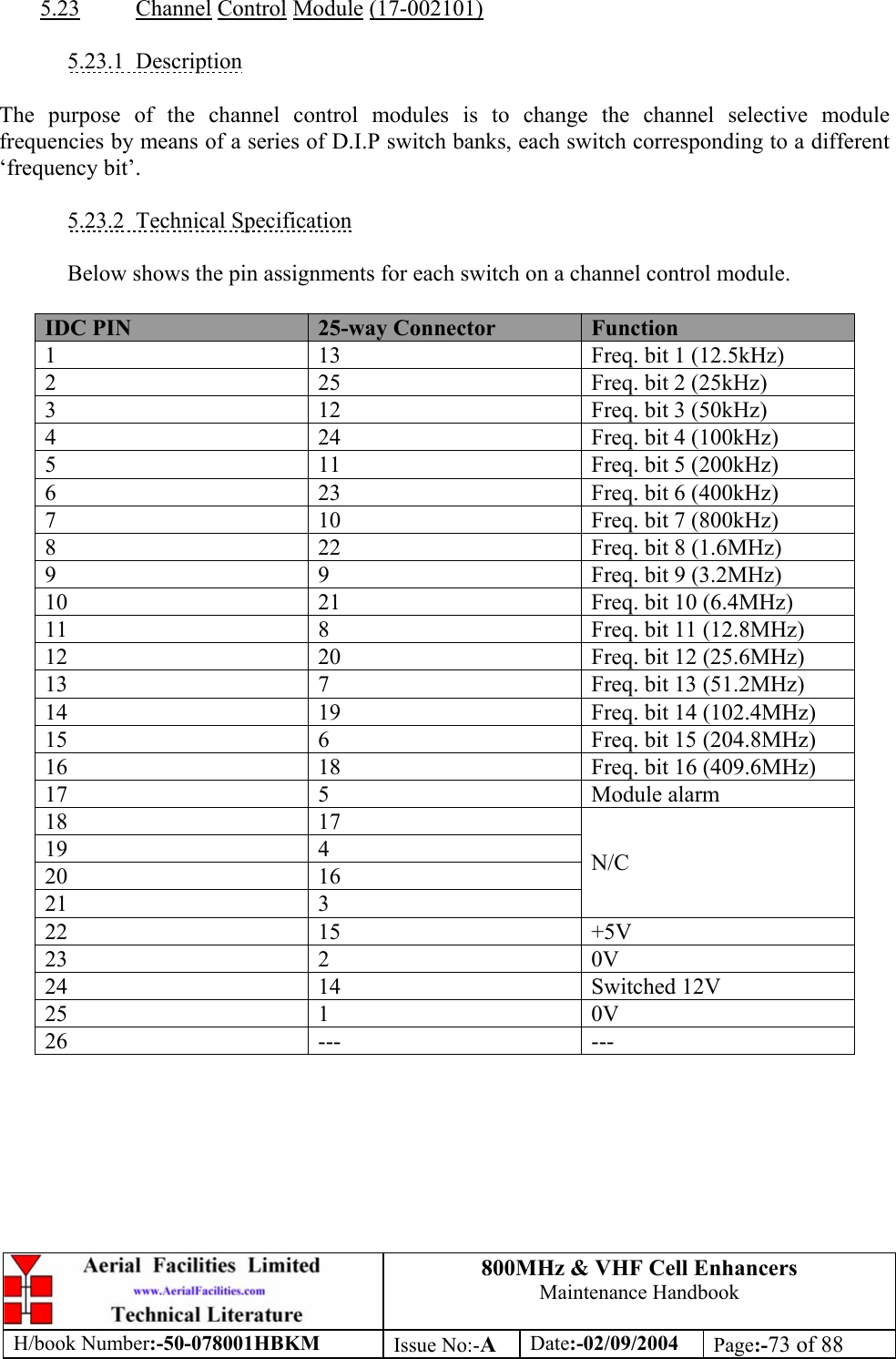
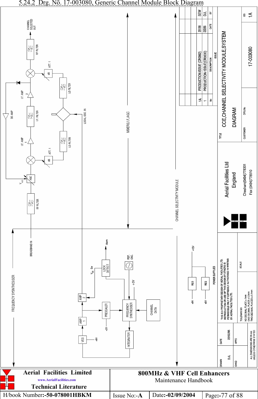
![800MHz & VHF Cell Enhancers Maintenance Handbook H/book Number:-50-078001HBKM Issue No:-A Date:-02/09/2004 Page:-33 of 88 3.4.2 800MHz AIF Uplink Shelf 50-078002 Parts List AFL Part Nō. Part Description Qty. 02-007201 900MHz 8POLE 10-20MHz B/W SMA 4 05-002602 900MHz SPLITTER/COMBINER, 20W 5 05-003801 3WAY GEN.SPLIT 900MHz GEN.ASS 4 10-000701 1/4W0-30dB SWITCHED ATTENUATOR 2 11-005902 900MHz LOW NOISE AMP WITH RELAY ASS 3 11-006702 GA 800-1000MHz LNA 29dB (WITH RELAY 4 12-018001 PA 800-960MHz 10W 30dB 2 14-000225 CASE RAIL LONG R.S.A./R.F.A. 4 17-001109 CE AGC UNIT LOG DET/AMP ASSY (12v) 1 17-001201 C/E AGC UNIT ATTENUATOR ASSY 1 20-001601 12V RELAY BOARD 1 50-012820 CCE RACK MOUNTED 8U CHASSIS 1 50-012822 CCE RACK MOUNTED LID 1 50-012825 CCE RACK MOUNTED HEATSINK BRACKET 4 50-027720 RACK MTD CHAN C.E. MODIFIED HEATSIN 2 80-090822 C/E 8U FRONT PANEL, AFL (RAL7035) 1 80-310420 BCC 400W POWER SUPPLY HEATSINK 1 91-030002 N ADAPTOR PANEL FEMALE:FEMALE 4 91-130005 SMA BULKHEAD ADAPTOR F/F 12 91-500025 3 PIN RIGHT ANGLE FREE PLUG NC-X 3 91-510003 3 PIN R.ANGLE FREE SOC.NC-X. 3 91-510004 3 PIN PNL.MOUNT SOCKET NC-X 3 91-510032 20A SOCKET CONTACT PIN 4 91-520001 PWR MAINS INL FIXED/SOLD.TERMS 1 91-520005 MAINS LEAD (KETTLE, IEC) 1 91-520010 MAINS RETAINING CLIP 1 91-600007 'D' 9 WAY BLACK SHELL 8 91-600014 'D' 9 WAY SOCKET S/B (NON FILTERED) 7 91-600015 'D' 9 WAY PLUG S/B (NON FILTERED) 1 91-660001 2W5 MIXED D TYPE SOCKET (7 WAY) 2 96-110034 FUSE HOLDER 16-30A, 32mm BODY 3 96-300057 15V 27A PSU 400W (XP BCC) 1 96-700034 LED RED 5mm IP67 INTEGRAL RES. 24V 1 96-700035 LED GREEN 5mm IP67 INTEGRAL RES 24V 1 96-900018 AC TRIP SWITCH (5 AMP M.C.B.) 2 97-400005 HANDLE TYPE H6802 3U [ALLOY] 2 99-200008 DANGER HIGH VOLTAGE LABEL 2x2' 1 99-200017 CAUTION HEAVY LABEL 75x55mm 2](https://usermanual.wiki/PBE-Europe-as-Axell-Wireless/50-0780-VHF/User-Guide-484300-Page-33.png)
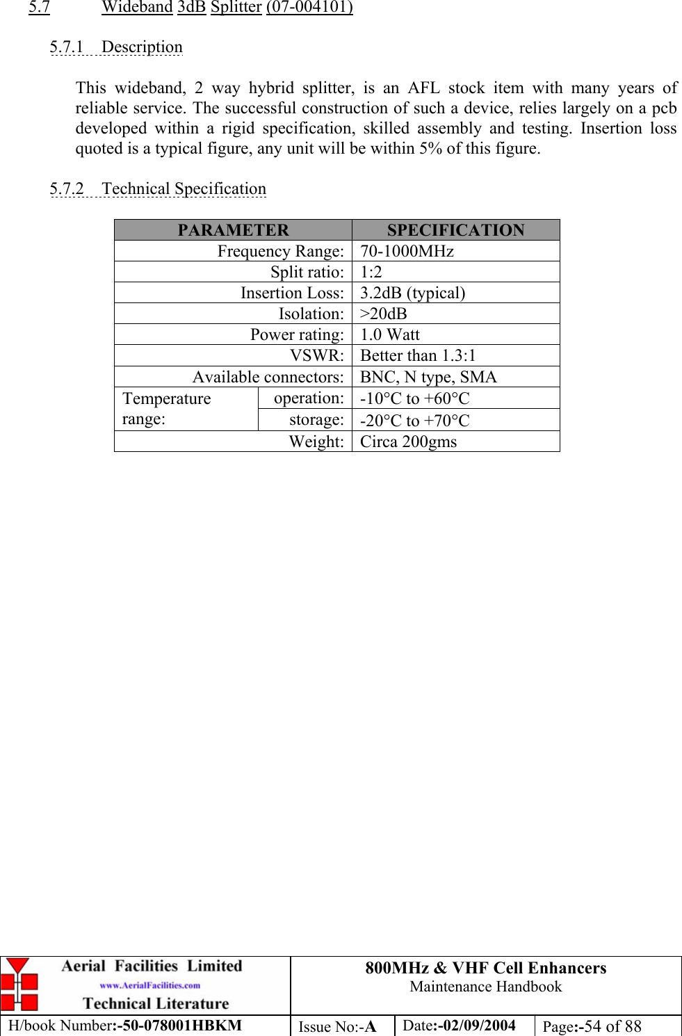
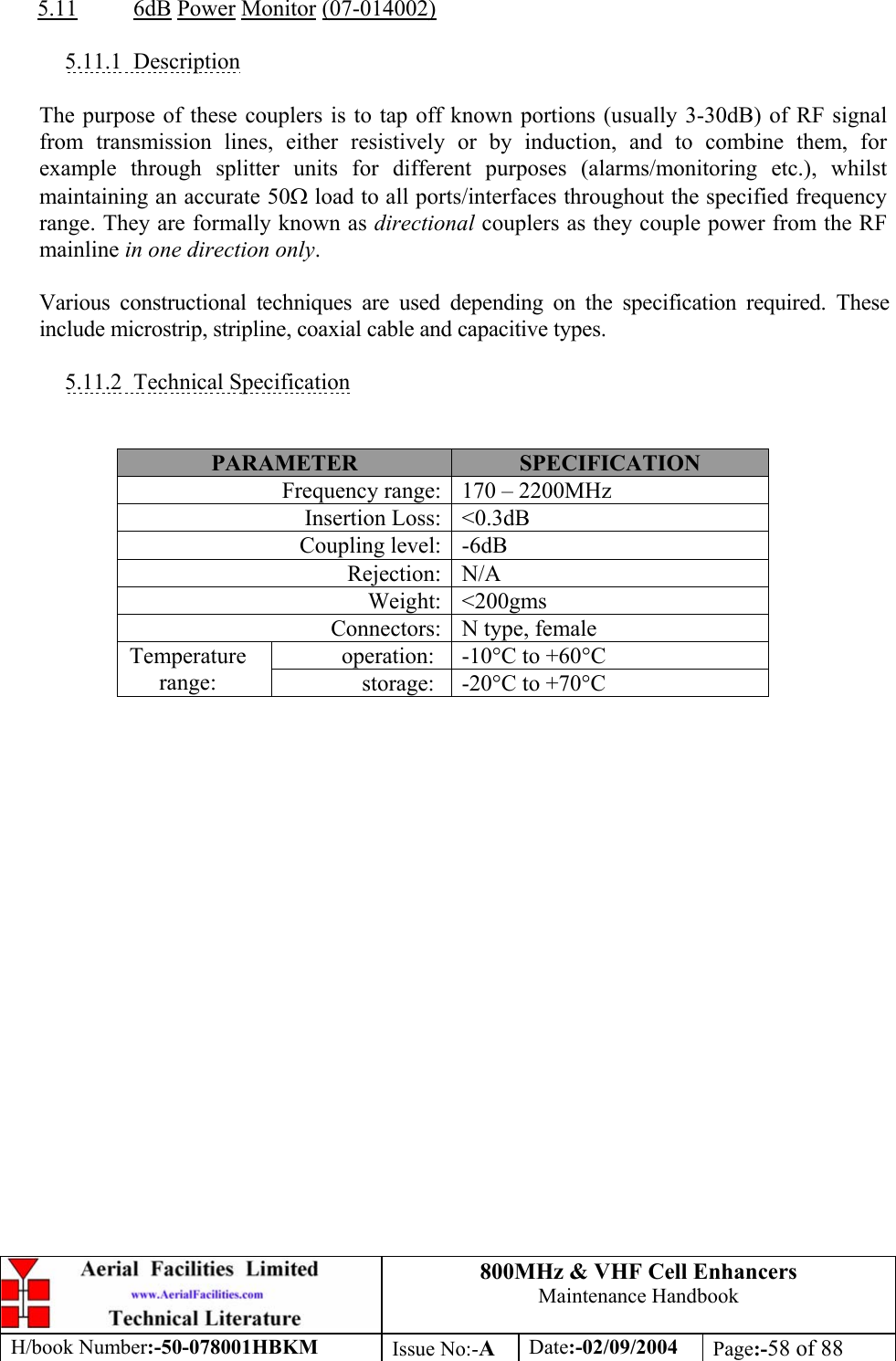
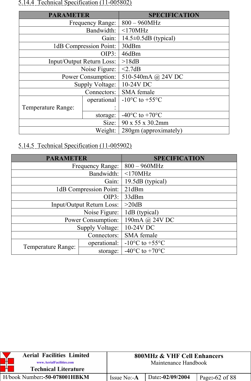
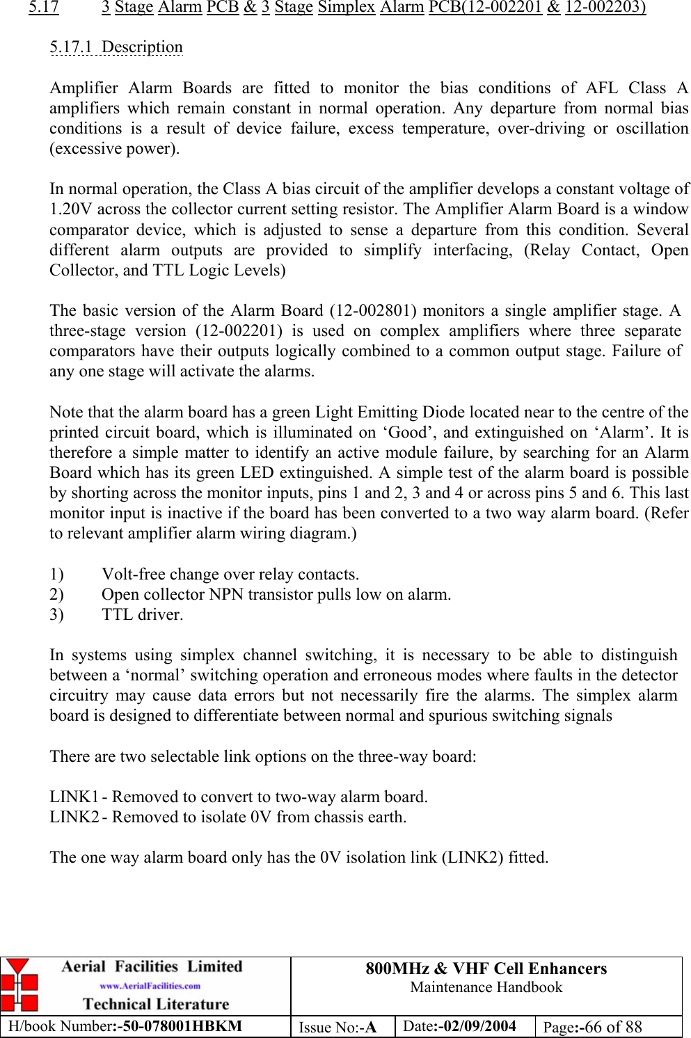
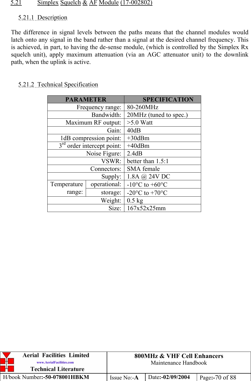
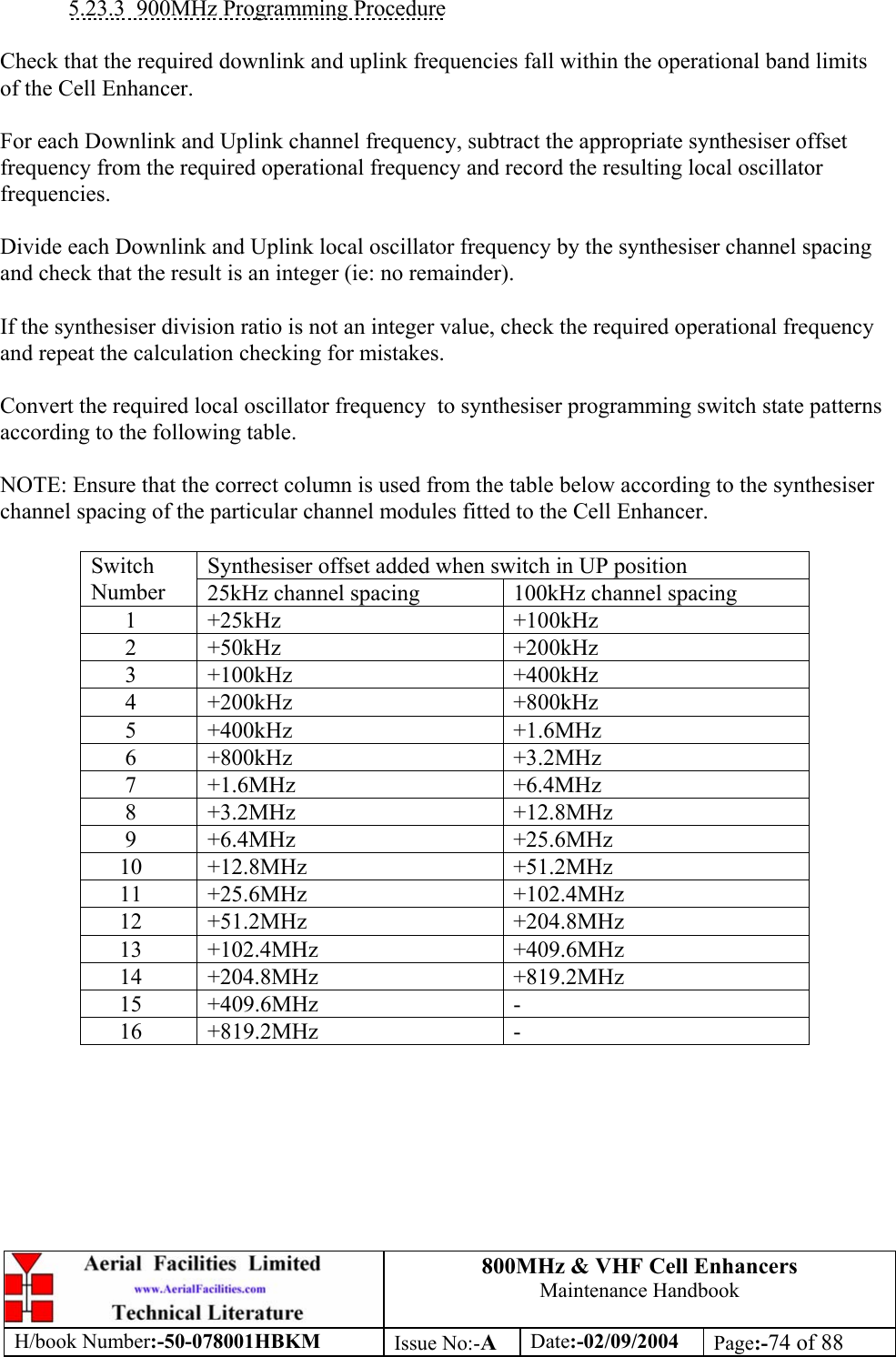
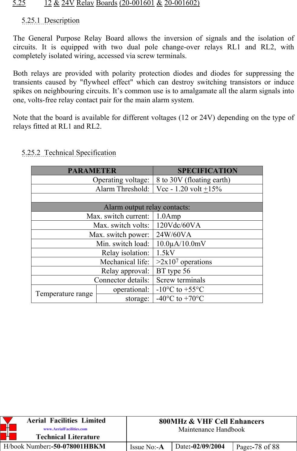
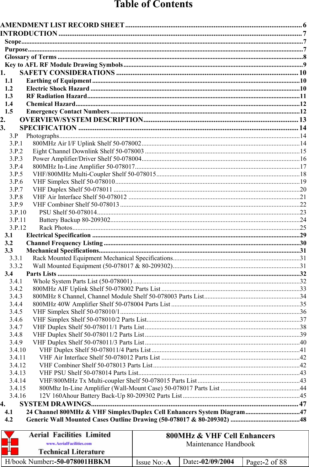
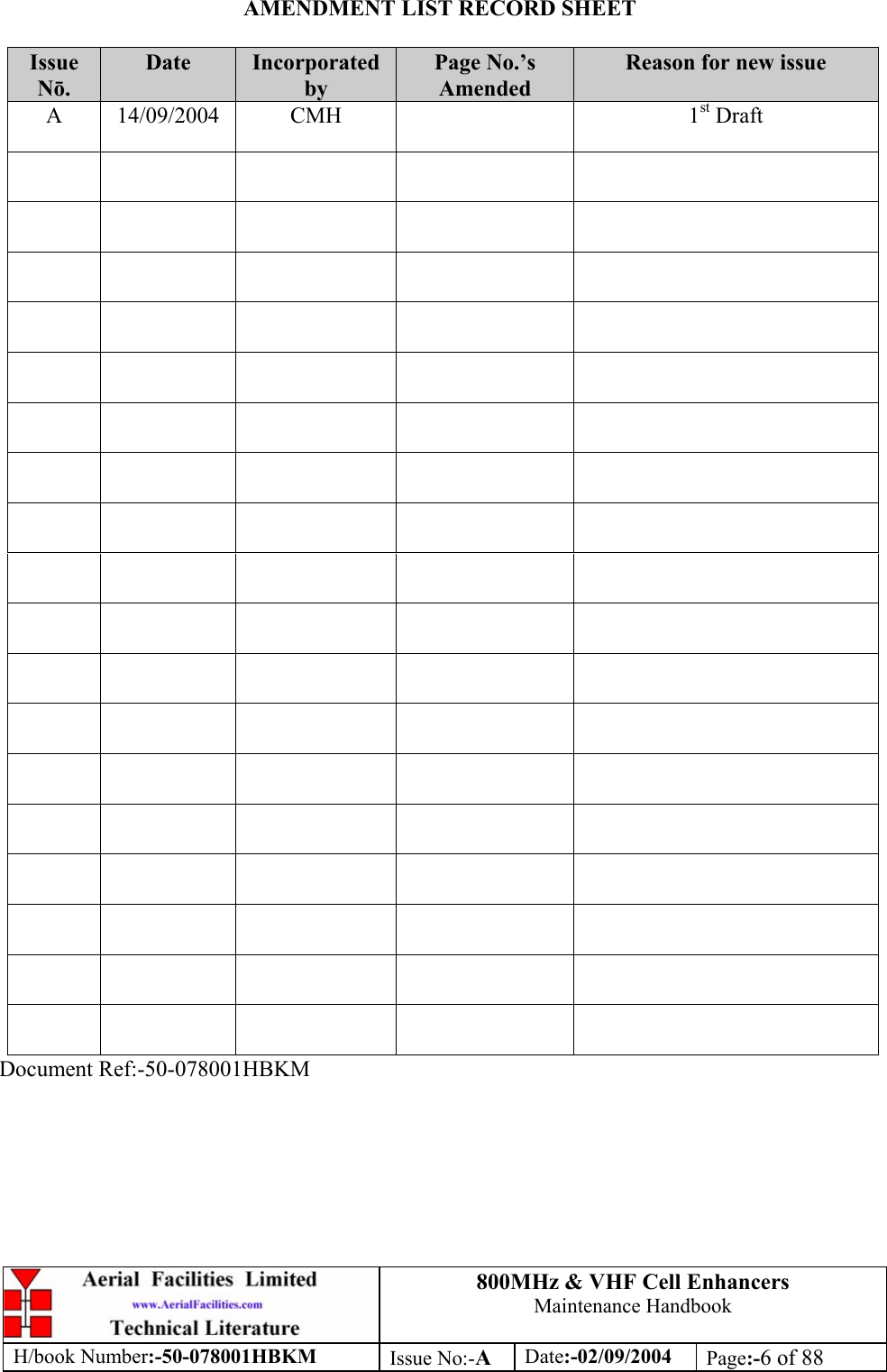
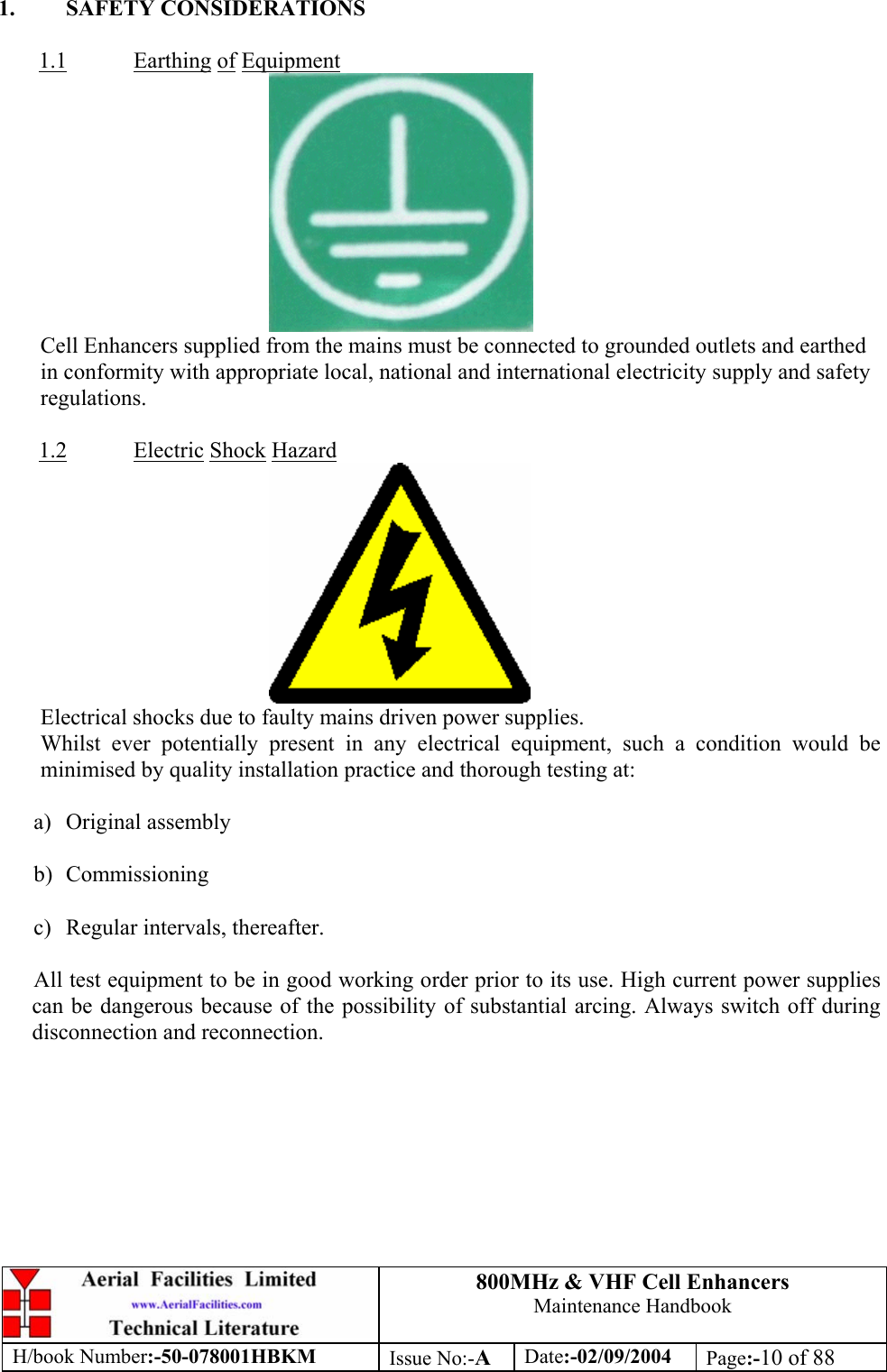
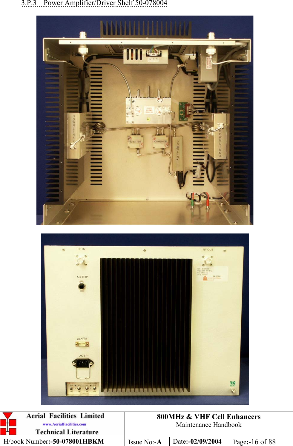
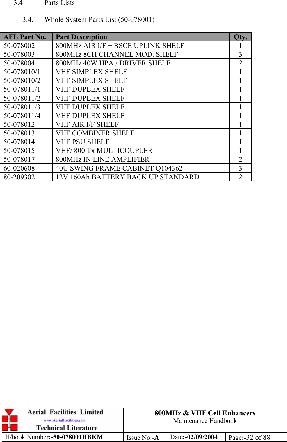
![800MHz & VHF Cell Enhancers Maintenance Handbook H/book Number:-50-078001HBKM Issue No:-A Date:-02/09/2004 Page:-35 of 88 3.4.4 800MHz 40W Amplifier Shelf 50-078004 Parts List AFL Part Nō. Part Description Qty. 02-007201 900MHz 8POLE 10-20MHz B/W SMA 1 05-002602 900MHz SPLITTER/COMBINER, 20W 2 10-000901 SW. ATTENUATOR 0.25W 0-15dB 1 11-005802 900MHz DRIVER STAGE WITH RELAY 1 12-018002 PA 800-960MHz 20W CLASS A 2 14-000225 CASE RAIL LONG R.S.A./R.F.A. 2 50-012820 CCE RACK MOUNTED 8U CHASSIS 1 50-012822 CCE RACK MOUNTED LID 1 50-012825 CCE RACK MOUNTED HEATSINK BRACKET 4 50-027720 RACK MTD CHAN C.E. MODIFIED HEATSIN 2 80-090822 C/E 8U FRONT PANEL, AFL (RAL7035) 1 80-310420 BCC 400W POWER SUPPLY HEATSINK 1 91-030002 N ADAPTOR PANEL FEMALE:FEMALE 2 91-510032 20A SOCKET CONTACT PIN 4 91-520001 PWR MAINS INL FIXED/SOLD.TERMS 1 91-520005 MAINS LEAD (KETTLE, IEC) 1 91-520010 MAINS RETAINING CLIP 1 91-600007 'D' 9 WAY BLACK SHELL 1 91-600014 'D' 9 WAY SOCKET S/B (NON FILTERED) 1 91-600015 'D' 9 WAY PLUG S/B (NON FILTERED) 1 91-660001 2W5 MIXED D TYPE SOCKET (7 WAY) 2 96-300057 15V 27A PSU 400W (XP BCC) 1 96-700034 LED RED 5mm IP67 INTEGRAL RES. 24V 1 96-700035 LED GREEN 5mm IP67 INTEGRAL RES 24V 1 96-900018 AC TRIP SWITCH (5 AMP M.C.B.) 1 97-400005 HANDLE TYPE H6802 3U [ALLOY] 2 99-200008 DANGER HIGH VOLTAGE LABEL 2x2' 1 99-200017 CAUTION HEAVY LABEL 75x55mm 2](https://usermanual.wiki/PBE-Europe-as-Axell-Wireless/50-0780-VHF/User-Guide-484300-Page-35.png)
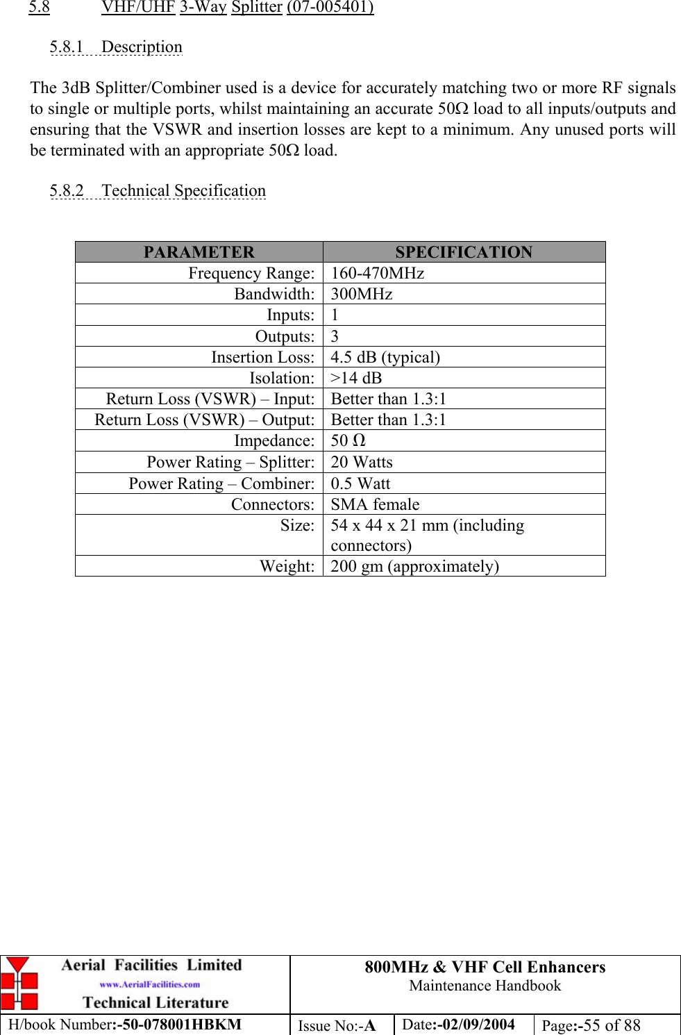
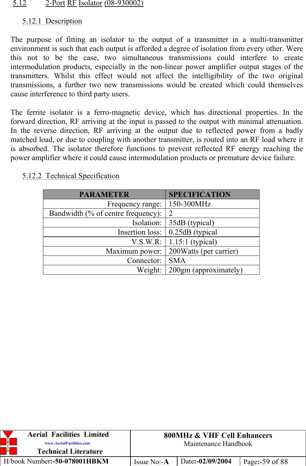
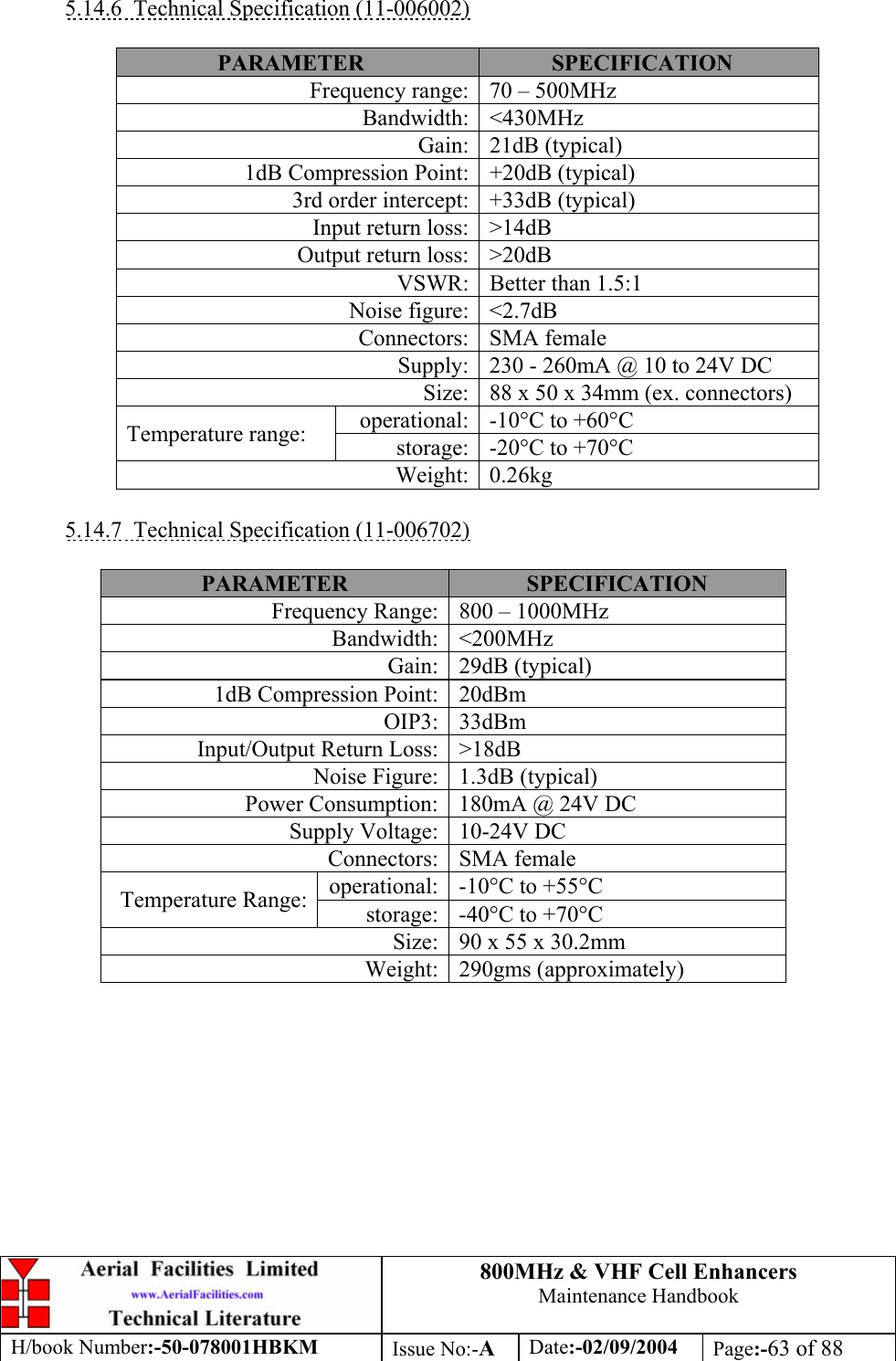
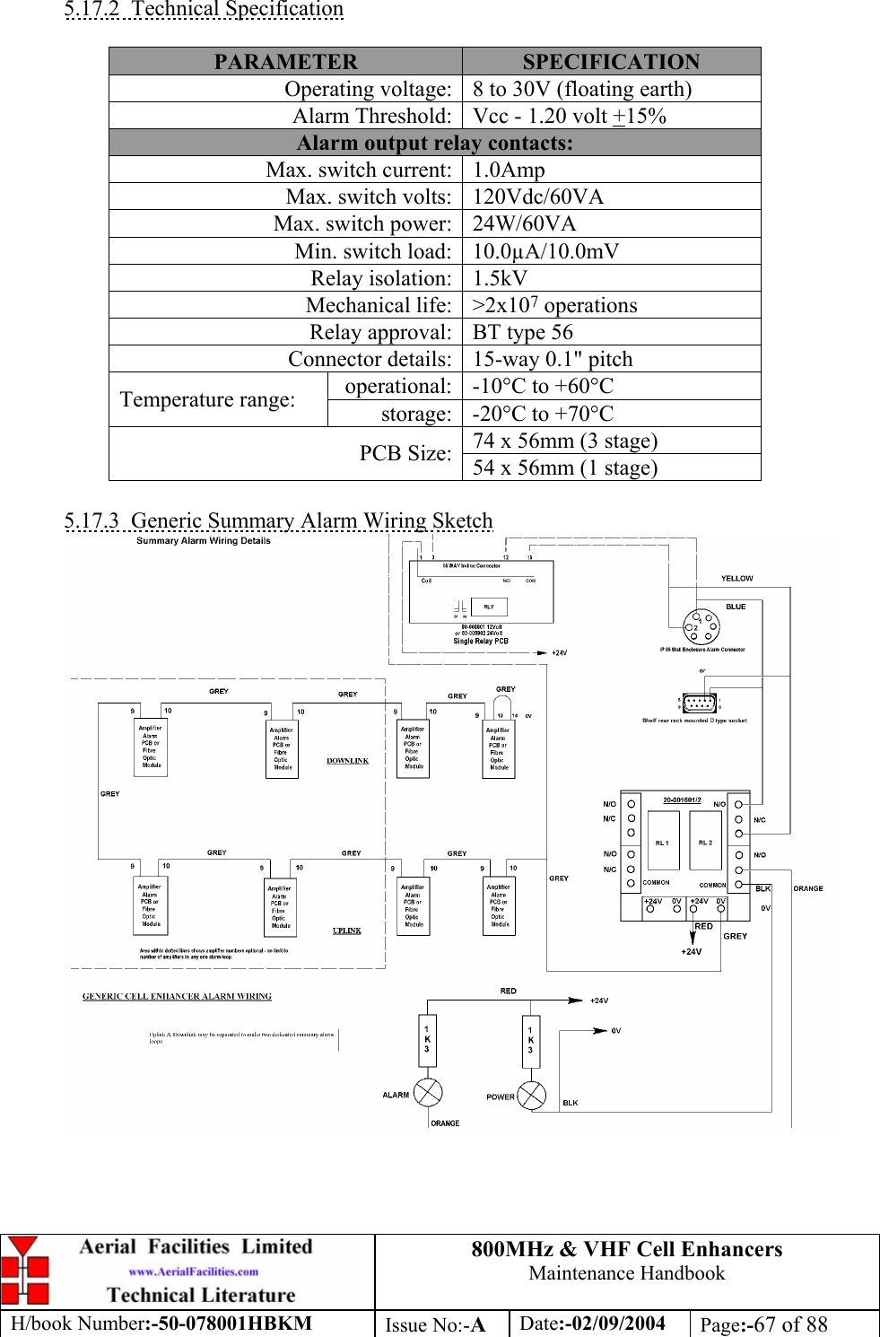
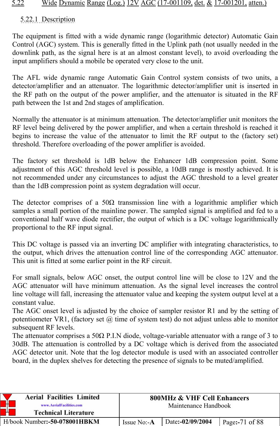
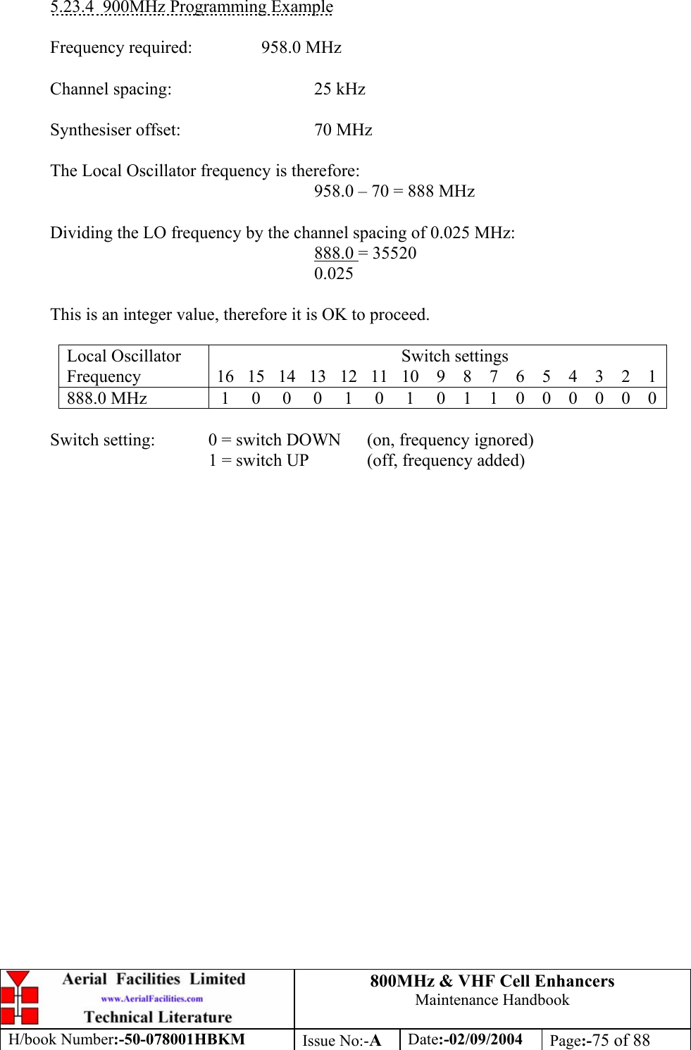
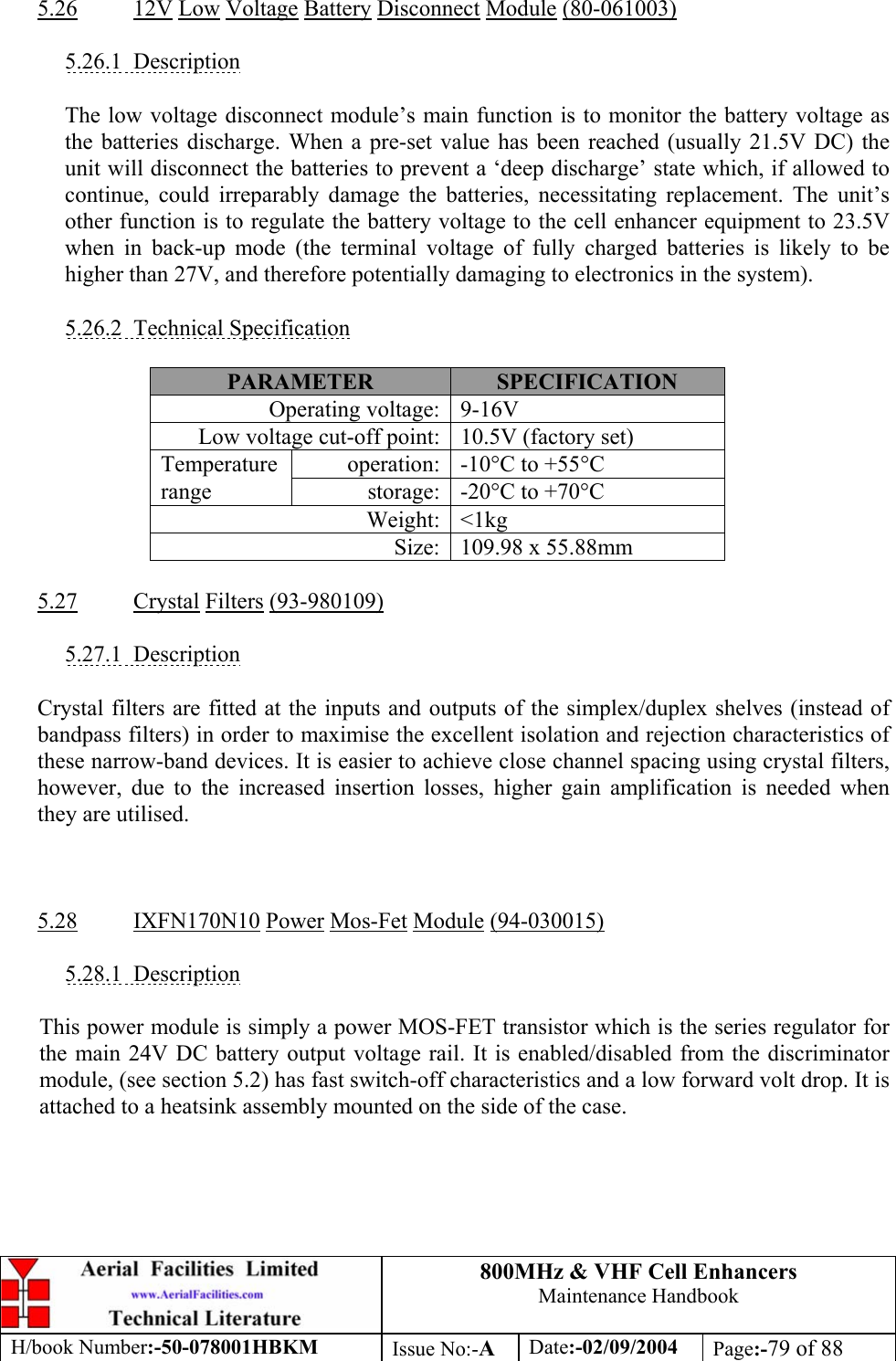
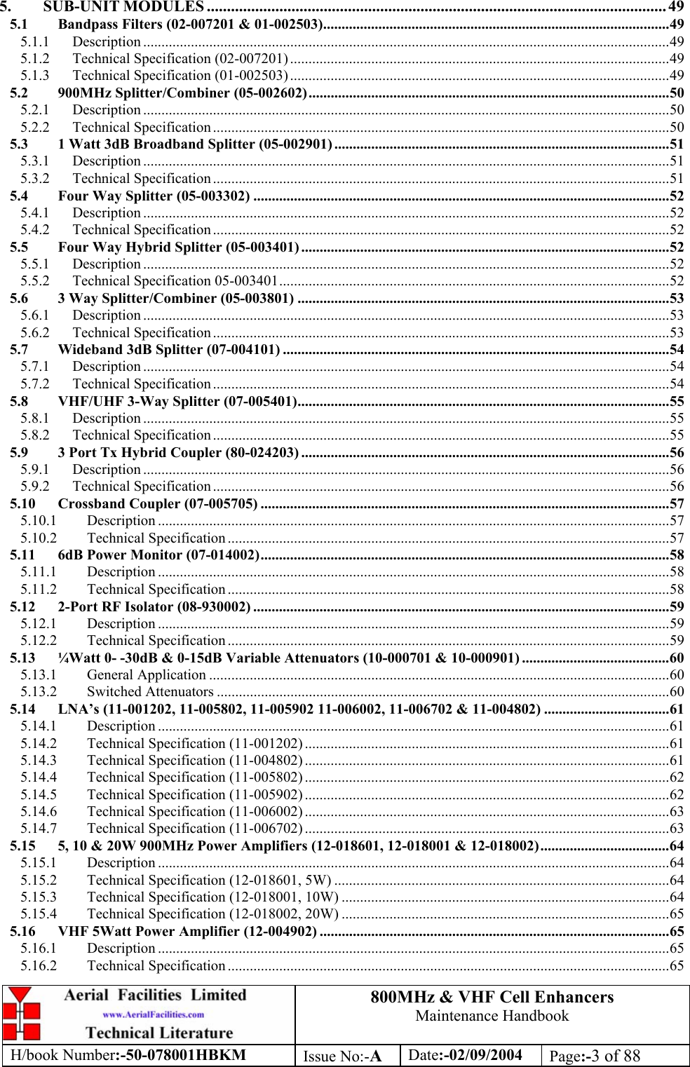
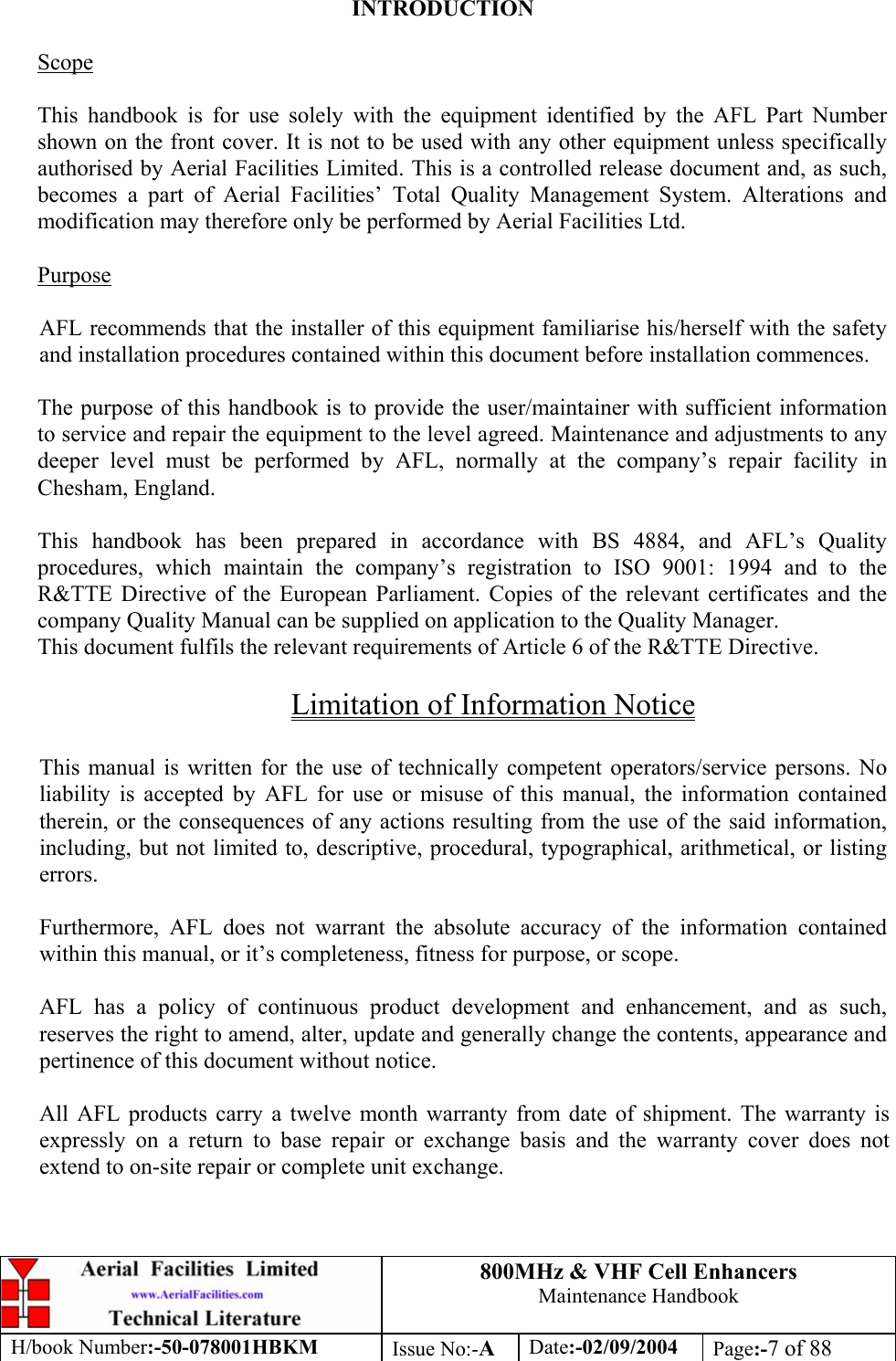
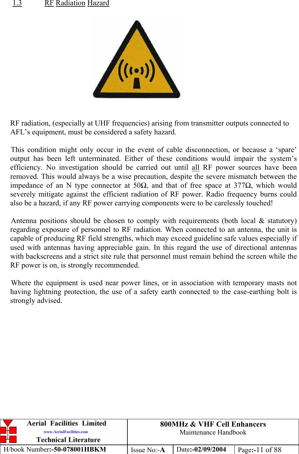
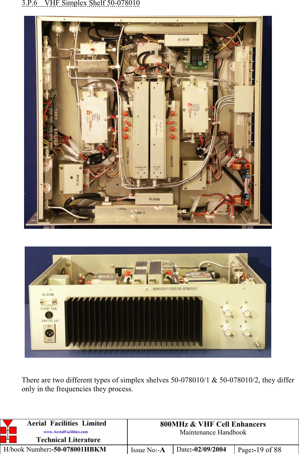
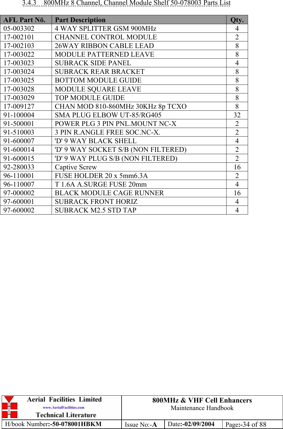
![800MHz & VHF Cell Enhancers Maintenance Handbook H/book Number:-50-078001HBKM Issue No:-A Date:-02/09/2004 Page:-36 of 88 3.4.5 VHF Simplex Shelf 50-078010/1 AFL Part Nō. Part Description Qty. 08-930002 2 PORT ISOLATOR 150-300MHz SMA 2 10-000901 SW. ATTENUATOR 0.25W 0-15dB 4 11-001202 10/600MHz LNA 24v SMA Alarm 7 12-002213 3 STAGE ALARM/SIMPLEXMUTE PCB SUB-ASS 2 12-002220 3 STAGE ALARM PCB COVER 2 12-002804 SINGLE CH. ALARM/SIMPLEX MUTE BOARD 7 12-002820 SINGLE CHANNEL ALARM COVER 7 12-004902 POWER AMP VHF 5W CLASS AB 2 13-001803 DUAL DC/DC CONVERTER 24V-12V 1A 1 13-001822 DC-DC CON 24V-5V/15V COVER 1 13-002811 SIMPLEX CONTROLLER PCB ASSEMBLY 2 17-001201 C/E AGC UNIT ATTENUATOR ASSY 4 17-002802 SIMPLEX C.E Rx/SQUELCH & AF (SMD) 2 17-009135 VHF 15Kstep CH MOD 15kHz 8p BW+IFRX 2 19-000826 2U,3U,4U 19" UNIT 400 DEEP LID 1 19-000921 3U 19" UNIT 400 DEEP CHASSIS + BKT 1 19-000924 3U 19" UNIT FRONT PANEL FAB 1 80-063920 HEATSINK 2U ASS140 (5W) MILCHBUCK 2 91-030002 N ADAPTOR PANEL FEMALE:FEMALE 4 91-500001 POWER PLG 3 PIN PNL.MOUNT NC-X 1 91-510003 3 PIN R.ANGLE FREE SOC.NC-X. 1 91-600001 'D'TYPE 9 WAY PLUG S/B TERM 1 91-600014 'D' 9 WAY SOCKET S/B (NON FILTERED) 2 91-620001 'D' 25 WAY SOCKET S/B TERM 2 91-700017 ICD 15 WAY 0.1' CONNECTOR 9 93-540035 1K3 0.25W 1% RES MRS25 M:F 2 93-980109 161.295MHz CRYSTAL FILT FAN4M52500 4 96-110001 FUSE HOLDER 20 x 5mm6.3A 1 96-300014 PSU VOLTS ADJUSTER 2 96-700017 LED AMBER 5mm SEALED IP66 2 96-700034 LED RED 5mm IP67 INTEGRAL RES. 24V 1 96-700035 LED GREEN 5mm IP67 INTEGRAL RES 24V 1 97-400005 HANDLE TYPE H6802 3U [ALLOY] 2](https://usermanual.wiki/PBE-Europe-as-Axell-Wireless/50-0780-VHF/User-Guide-484300-Page-36.png)
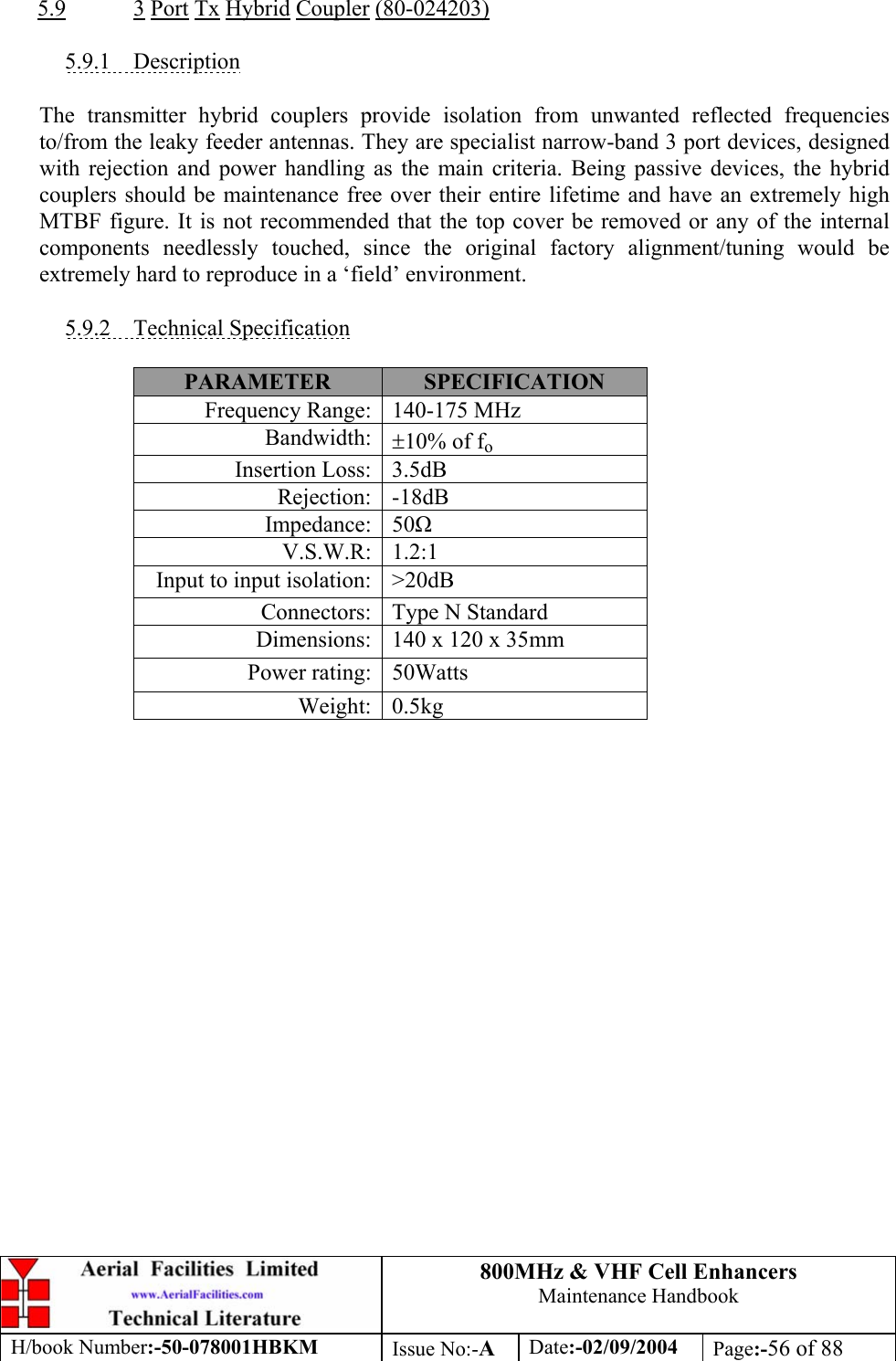
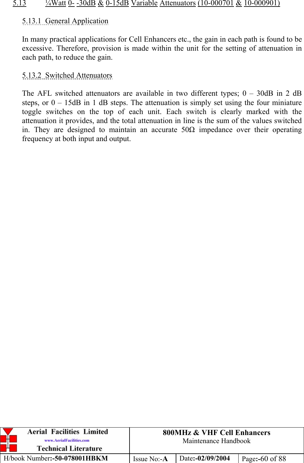
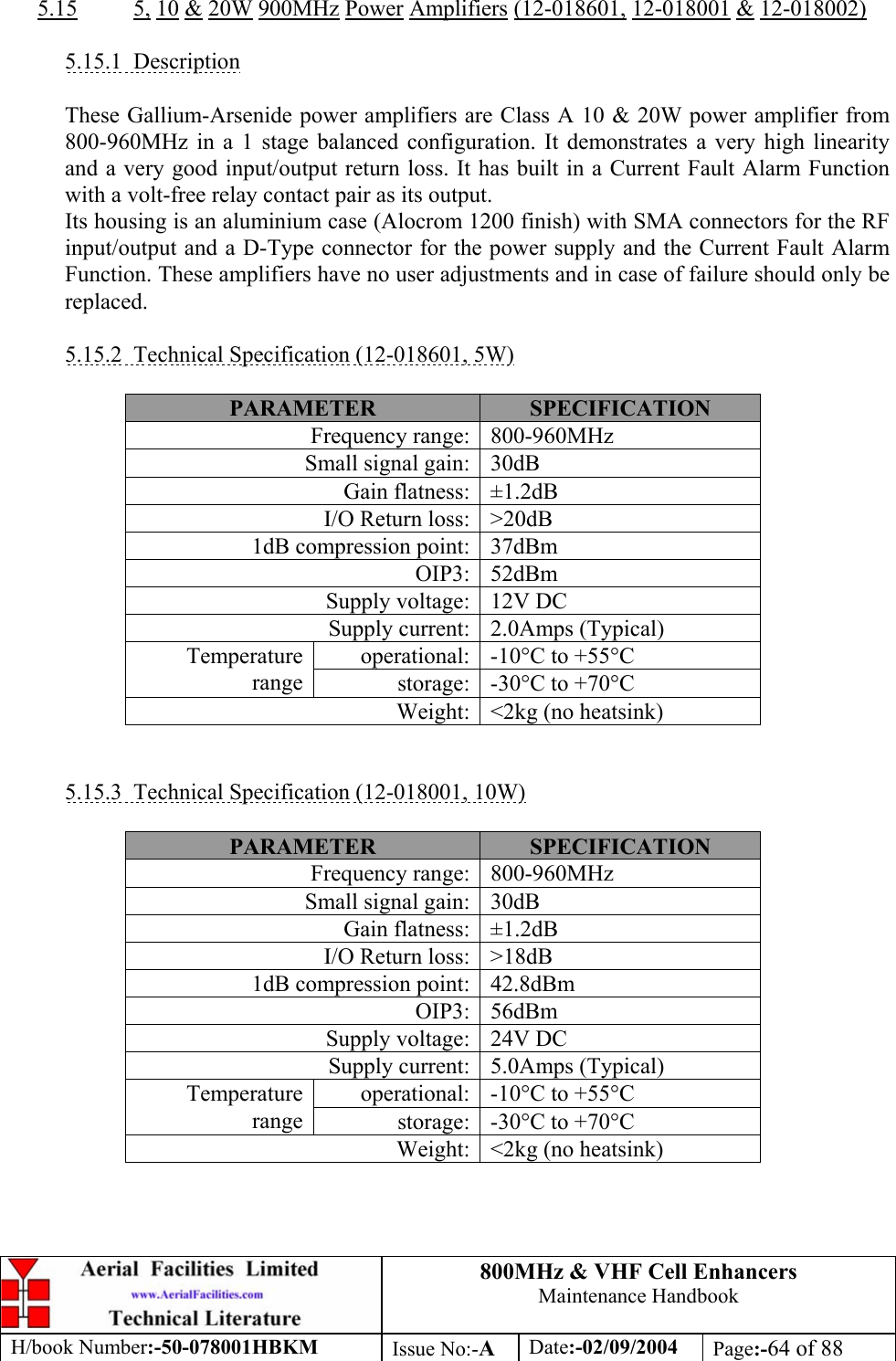
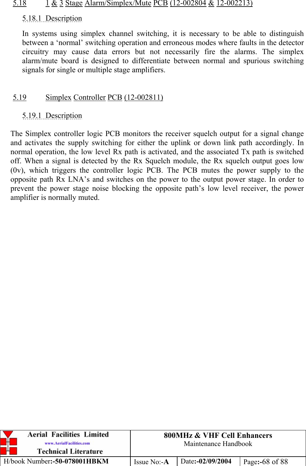
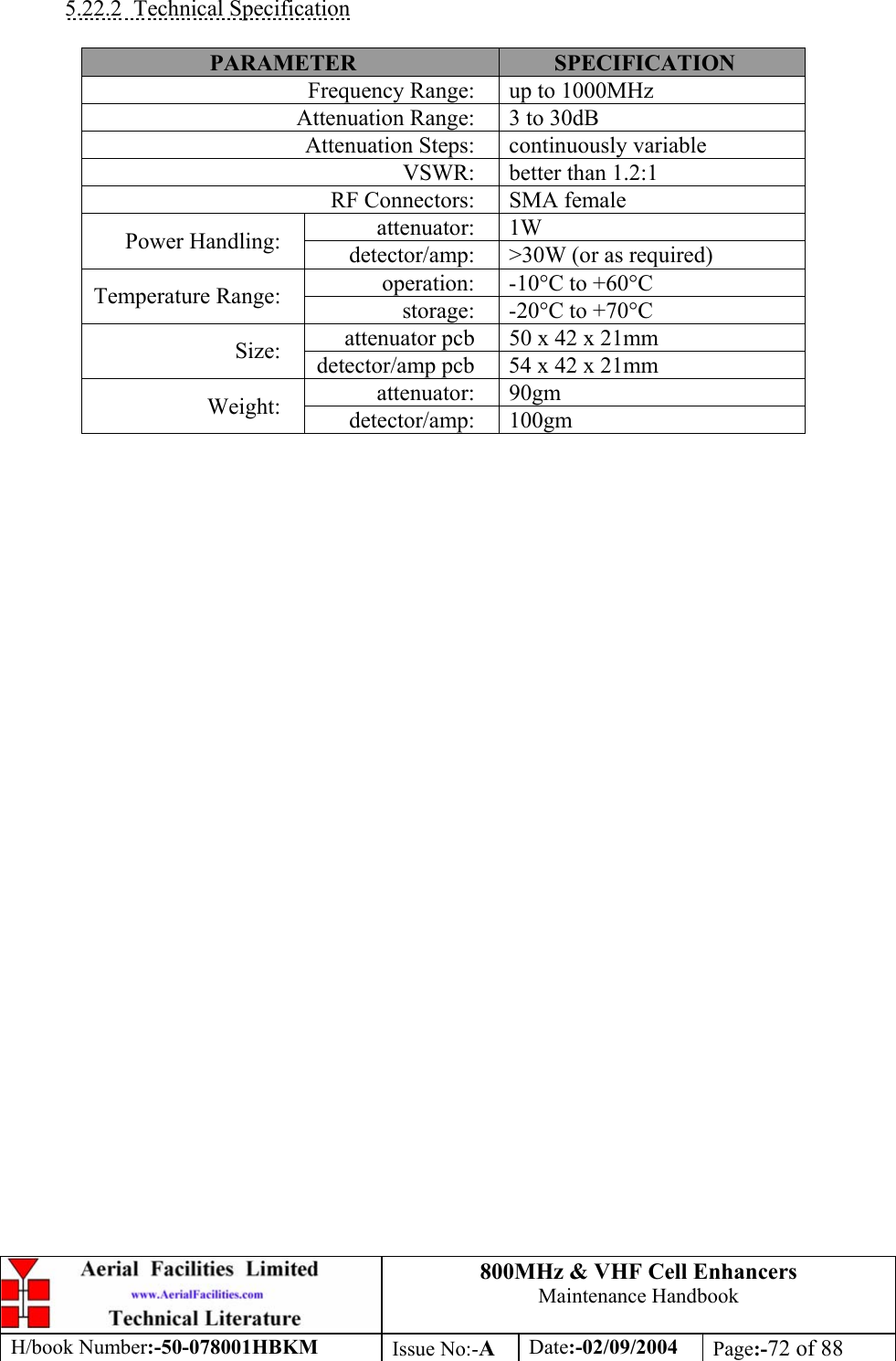
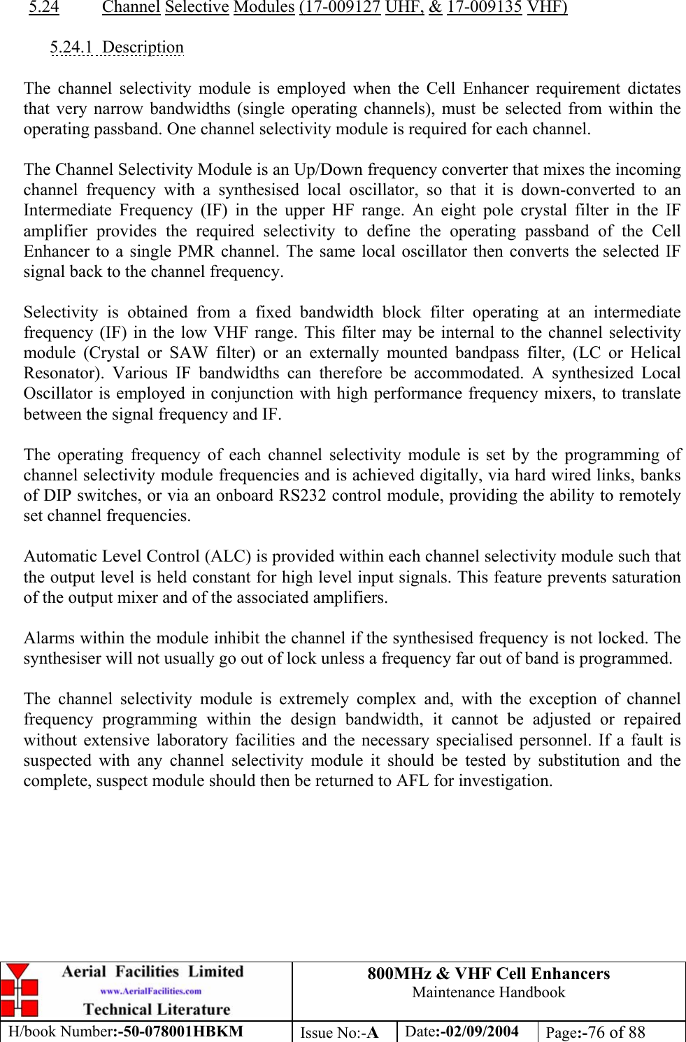
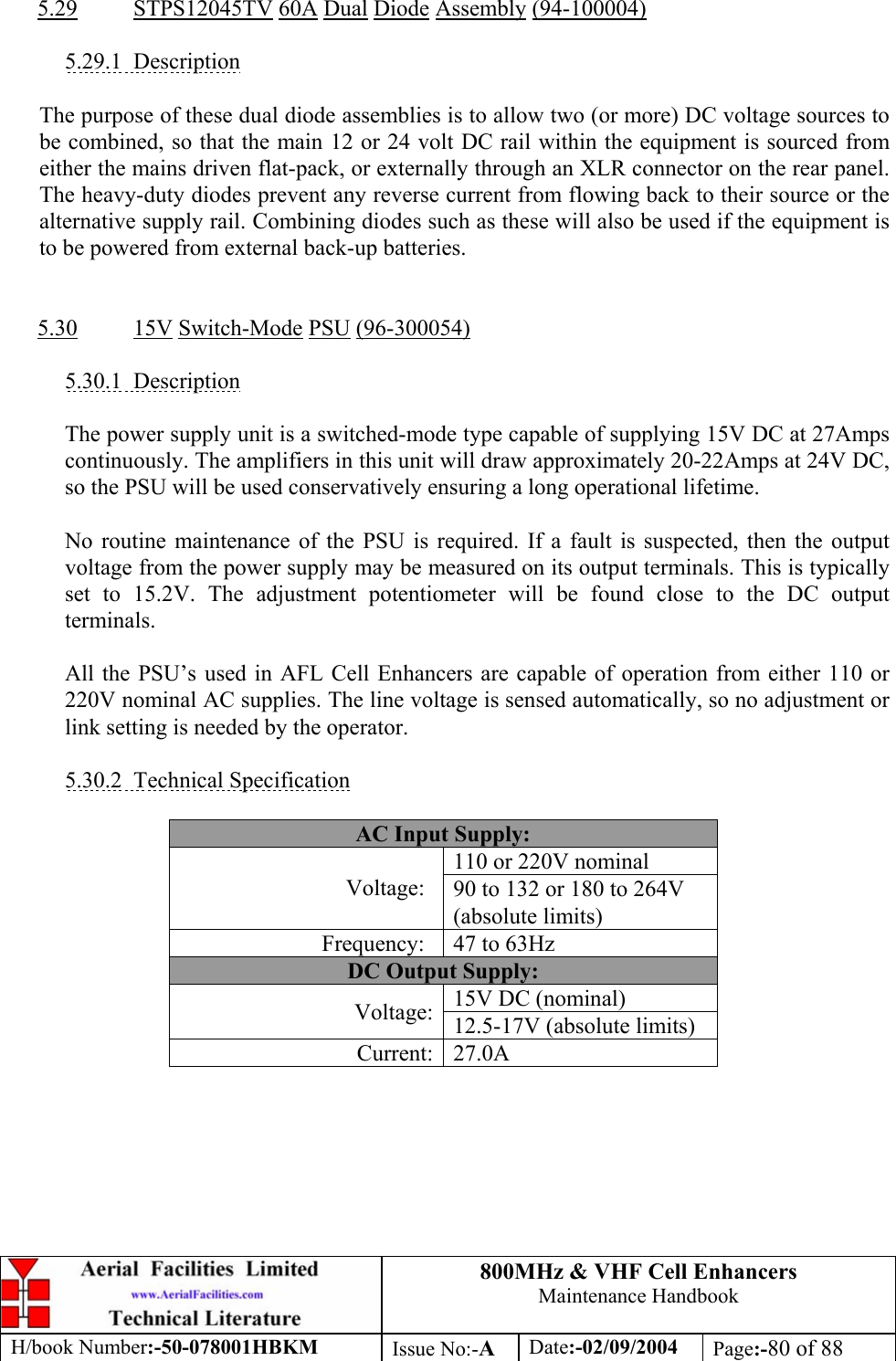
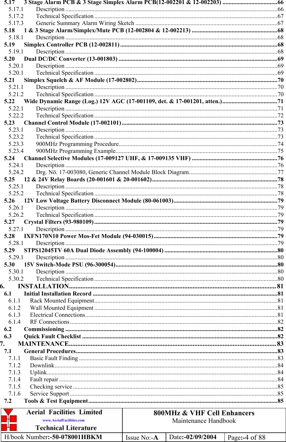
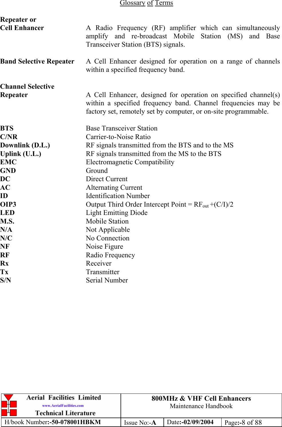
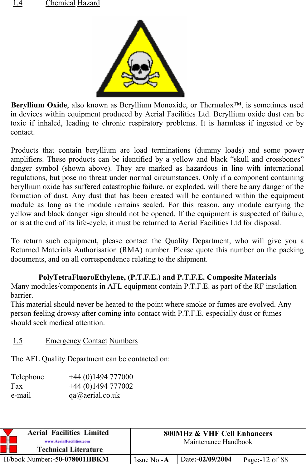
![800MHz & VHF Cell Enhancers Maintenance Handbook H/book Number:-50-078001HBKM Issue No:-A Date:-02/09/2004 Page:-37 of 88 3.4.6 VHF Simplex Shelf 50-078010/2 Parts List AFL Part Nō. Part Description Qty. 08-930002 2 PORT ISOLATOR 150-300MHz SMA 2 10-000901 SW. ATTENUATOR 0.25W 0-15dB 4 11-001202 10/600MHz LNA 24v SMA Alarm 7 12-002213 3 STAGE ALM/SIMPLEXMUTE PCB SUB-ASS 2 12-002220 3 STAGE ALARM PCB COVER 2 12-002804 SINGLE CH. ALARM/SIMPLEX MUTE BOARD 7 12-002820 SINGLE CHANNEL ALARM COVER 7 12-004902 POWER AMP VHF 5W CLASS AB 2 13-001803 DUAL DC/DC CONVERTER 24V-12V 1A 1 13-001822 DC-DC CON 24V-5V/15V COVER 1 13-002811 SIMPLEX CONTROLLER PCB ASSEMBLY 2 17-001201 C/E AGC UNIT ATTENUATOR ASSY 4 17-002802 SIMPLEX C.E Rx/SQUELCH & AF (SMD) 2 17-009135 VHF 15Kstep CH MOD 15kHz 8p BW+IFRX 2 19-000826 2U,3U,4U 19" UNIT 400 DEEP LID 1 19-000921 3U 19" UNIT 400 DEEP CHASSIS + BKT 1 19-000924 3U 19" UNIT FRONT PANEL FAB 1 80-063920 HEATSINK 2U ASS140 (5W) MILCHBUCK 2 91-030002 N ADAPTOR PANEL FEMALE:FEMALE 4 91-500001 POWER PLG 3 PIN PNL.MOUNT NC-X 1 91-510003 3 PIN R.ANGLE FREE SOC.NC-X. 1 91-600001 'D'TYPE 9 WAY PLUG S/B TERM 1 91-600014 'D' 9 WAY SOCKET S/B (NON FILTERED) 2 91-620001 'D' 25 WAY SOCKET S/B TERM 2 91-700017 ICD 15 WAY 0.1' CONNECTOR 9 93-540035 1K3 0.25W 1% RES MRS25 M:F 2 93-980112 160.530MHz CRYSTAL FILT FAN4M52500 4 96-110001 FUSE HOLDER 20 x 5mm6.3A 1 96-300014 PSU VOLTS ADJUSTER 2 96-700017 LED AMBER 5MM SEALED IP66 2 96-700034 LED RED 5mm IP67 INTEGRAL RES. 24V 1 96-700035 LED GREEN 5mm IP67 INTEGRAL RES 24V 1 97-400005 HANDLE TYPE H6802 3U [ALLOY] 2](https://usermanual.wiki/PBE-Europe-as-Axell-Wireless/50-0780-VHF/User-Guide-484300-Page-37.png)
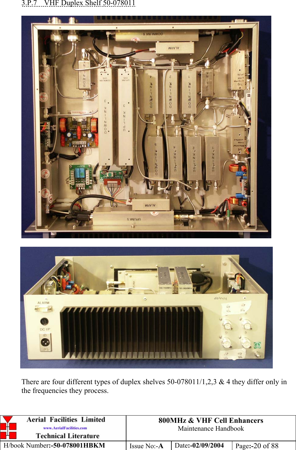
![800MHz & VHF Cell Enhancers Maintenance Handbook H/book Number:-50-078001HBKM Issue No:-A Date:-02/09/2004 Page:-38 of 88 3.4.7 VHF Duplex Shelf 50-078011/1 Parts List AFL Part Nō. Part Description Qty. 08-930002 2 PORT ISOLATOR 150-300MHz SMA 2 10-000901 SW. ATTENUATOR 0.25W 0-15dB 4 11-006002 LNA VHF 70-500MHz WITH RELAY 7 12-002201 3 STAGE AMPLIFIER ALARM BOARD 1 12-002203 3 STAGE ALARM BOARD SIMPLEX 1 12-002220 3 STAGE ALARM PCB COVER 2 12-004902 POWER AMP VHF 5W CLASS AB 2 13-001803 DUAL DC/DC CONVERTER 24V-12V 1A 2 13-001822 DC-DC CON 24V-5V/15V COVER 1 13-002812 SWITCH VERSION OF SIMPLEX CONT. 1 17-001105 CE AGC UNIT LOG DET/AMP ASSY (24v) 1 17-009135 VHF 15Kstep CH MOD 15kHz 8p BW+IFRX 2 19-000826 2U,3U,4U 19" UNIT 400 DEEP LID 1 19-000921 3U 19" UNIT 400 DEEP CHASSIS + BKT 1 19-000924 3U 19" UNIT FRONT PANEL FAB 1 80-063920 HEATSINK 2U ASS140 (5W) MILCHBUCK 2 91-030002 N ADAPTOR PANEL FEMALE:FEMALE 4 91-500001 POWER PLG 3 PIN PNL.MOUNT NC-X 1 91-510003 3 PIN R.ANGLE FREE SOC.NC-X. 1 91-600001 'D'TYPE 9 WAY PLUG S/B TERM 1 91-600014 'D' 9 WAY SOCKET S/B (NON FILTERED) 7 91-620001 'D' 25 WAY SOCKET S/B TERM 2 91-700017 ICD 15 WAY 0.1' CONNECTOR 2 93-980103 160.665MHz CRYSTAL FILT FAN4M52500 2 93-980104 160.935MHz CRYSTAL FILT FAN4M52500 2 96-110001 FUSE HOLDER 20 x 5mm6.3A 1 96-700034 LED RED 5mm IP67 INTEGRAL RES. 24V 1 96-700035 LED GREEN 5mm IP67 INTEGRAL RES 24V 1 97-400005 HANDLE TYPE H6802 3U [ALLOY] 2](https://usermanual.wiki/PBE-Europe-as-Axell-Wireless/50-0780-VHF/User-Guide-484300-Page-38.png)
![800MHz & VHF Cell Enhancers Maintenance Handbook H/book Number:-50-078001HBKM Issue No:-A Date:-02/09/2004 Page:-39 of 88 3.4.8 VHF Duplex Shelf 50-078011/2 Parts List AFL Part Nō. Part Description Qty. 08-930002 2 PORT ISOLATOR 150-300MHz SMA 2 10-000901 SW. ATTENUATOR 0.25W 0-15dB 4 11-006002 LNA VHF 70-500MHz WITH RELAY 7 12-002201 3 STAGE AMPLIFIER ALARM BOARD 1 12-002203 3 STAGE ALARM BOARD SIMPLEX 1 12-002220 3 STAGE ALARM PCB COVER 2 12-004902 POWER AMP VHF 5W CLASS AB 2 13-001803 DUAL DC/DC CONVERTER 24V-12V 1A 2 13-001822 DC-DC CON 24V-5V/15V COVER 1 13-002812 SWITCH VERSION OF SIMPLEX CONT. 1 17-001105 CE AGC UNIT LOG DET/AMP ASSY (24v) 1 17-009135 VHF 15Kstep CH MOD 15kHz 8p BW+IFRX 2 19-000826 2U,3U,4U 19" UNIT 400 DEEP LID 1 19-000921 3U 19" UNIT 400 DEEP CHASSIS + BKT 1 19-000924 3U 19" UNIT FRONT PANEL FAB 1 80-063920 HEATSINK 2U ASS140 (5W) MILCHBUCK 2 91-030002 N ADAPTOR PANEL FEMALE:FEMALE 4 91-500001 POWER PLG 3 PIN PNL.MOUNT NC-X 1 91-510003 3 PIN R.ANGLE FREE SOC.NC-X. 1 91-600001 'D'TYPE 9 WAY PLUG S/B TERM 1 91-600014 'D' 9 WAY SOCKET S/B (NON FILTERED) 7 91-620001 'D' 25 WAY SOCKET S/B TERM 2 91-700017 ICD 15 WAY 0.1' CONNECTOR 2 93-980105 160.380MHz CRYSTAL FILT FAN4M52500 2 93-980106 160.905MHz CRYSTAL FILT FAN4M52500 2 96-110001 FUSE HOLDER 20 x 5mm6.3A 1 96-700034 LED RED 5mm IP67 INTEGRAL RES. 24V 1 96-700035 LED GREEN 5mm IP67 INTEGRAL RES 24V 1 97-400005 HANDLE TYPE H6802 3U [ALLOY] 2](https://usermanual.wiki/PBE-Europe-as-Axell-Wireless/50-0780-VHF/User-Guide-484300-Page-39.png)
![800MHz & VHF Cell Enhancers Maintenance Handbook H/book Number:-50-078001HBKM Issue No:-A Date:-02/09/2004 Page:-40 of 88 3.4.9 VHF Duplex Shelf 50-078011/3 Parts List AFL Part Nō. Part Description Qty. 08-930002 2 PORT ISOLATOR 150-300MHz SMA 2 10-000901 SW. ATTENUATOR 0.25W 0-15dB 4 11-006002 LNA VHF 70-500MHz WITH RELAY 7 12-002201 3 STAGE AMPLIFIER ALARM BOARD 1 12-002203 3 STAGE ALARM BOARD SIMPLEX 1 12-002220 3 STAGE ALARM PCB COVER 2 12-004902 POWER AMP VHF 5W CLASS AB 2 13-001803 DUAL DC/DC CONVERTER 24V-12V 1A 2 13-001822 DC-DC CON 24V-5V/15V COVER 1 13-002812 SWITCH VERSION OF SIMPLEX CONT. 1 17-001105 CE AGC UNIT LOG DET/AMP ASSY (24v) 1 17-009135 VHF 15Kstep CH MOD 15kHz 8p BW+IFRX 2 19-000826 2U,3U,4U 19" UNIT 400 DEEP LID 1 19-000921 3U 19" UNIT 400 DEEP CHASSIS + BKT 1 19-000924 3U 19" UNIT FRONT PANEL FAB 1 80-063920 HEATSINK 2U ASS140 (5W) MILCHBUCK 2 91-030002 N ADAPTOR PANEL FEMALE:FEMALE 4 91-500001 POWER PLG 3 PIN PNL.MOUNT NC-X 1 91-510003 3 PIN R.ANGLE FREE SOC.NC-X. 1 91-600001 'D'TYPE 9 WAY PLUG S/B TERM 1 91-600014 'D' 9 WAY SOCKET S/B (NON FILTERED) 7 91-620001 'D' 25 WAY SOCKET S/B TERM 2 91-700017 ICD 15 WAY 0.1' CONNECTOR 2 93-980107 160.710MHz CRYSTAL FILT FAN4M52500 2 93-980108 161.415MHz CRYSTAL FILT FAN4M52500 2 96-110001 FUSE HOLDER 20 x 5mm6.3A 1 96-700034 LED RED 5mm IP67 INTEGRAL RES. 24V 1 96-700035 LED GREEN 5mm IP67 INTEGRAL RES 24V 1 97-400005 HANDLE TYPE H6802 3U [ALLOY] 2](https://usermanual.wiki/PBE-Europe-as-Axell-Wireless/50-0780-VHF/User-Guide-484300-Page-40.png)
![800MHz & VHF Cell Enhancers Maintenance Handbook H/book Number:-50-078001HBKM Issue No:-A Date:-02/09/2004 Page:-41 of 88 3.4.10 VHF Duplex Shelf 50-078011/4 Parts List AFL Part Nō. Part Description Qty. 08-930002 2 PORT ISOLATOR 150-300MHz SMA 2 10-000901 SW. ATTENUATOR 0.25W 0-15dB 4 11-006002 LNA VHF 70-500MHz WITH RELAY 7 12-002201 3 STAGE AMPLIFIER ALARM BOARD 1 12-002203 3 STAGE ALARM BOARD SIMPLEX 1 12-002220 3 STAGE ALARM PCB COVER 2 12-004902 POWER AMP VHF 5W CLASS AB 2 13-001803 DUAL DC/DC CONVERTER 24V-12V 1A 2 13-001822 DC-DC CON 24V-5V/15V COVER 1 13-002812 SWITCH VERSION OF SIMPLEX CONT. 1 17-001105 CE AGC UNIT LOG DET/AMP ASSY (24v) 1 17-009135 VHF 15Kstep CH MOD 15kHz 8p BW+IFRX 2 19-000826 2U,3U,4U 19" UNIT 400 DEEP LID 1 19-000921 3U 19" UNIT 400 DEEP CHASSIS + BKT 1 19-000924 3U 19" UNIT FRONT PANEL FAB 1 80-063920 HEATSINK 2U ASS140 (5W) MILCHBUCK 2 91-030002 N ADAPTOR PANEL FEMALE:FEMALE 4 91-500001 POWER PLG 3 PIN PNL.MOUNT NC-X 1 91-510003 3 PIN R.ANGLE FREE SOC.NC-X. 1 91-600001 'D'TYPE 9 WAY PLUG S/B TERM 1 91-600014 'D' 9 WAY SOCKET S/B (NON FILTERED) 7 91-620001 'D' 25 WAY SOCKET S/B TERM 2 91-700017 ICD 15 WAY 0.1' CONNECTOR 2 93-980110 161.565MHz CRYSTAL FILT FAN4M52500 2 93-980111 160.755MHz CRYSTAL FILT FAN4M52500 2 96-110001 FUSE HOLDER 20 x 5mm6.3A 1 96-700034 LED RED 5mm IP67 INTEGRAL RES. 24V 1 96-700035 LED GREEN 5mm IP67 INTEGRAL RES 24V 1 97-400005 HANDLE TYPE H6802 3U [ALLOY] 2](https://usermanual.wiki/PBE-Europe-as-Axell-Wireless/50-0780-VHF/User-Guide-484300-Page-41.png)
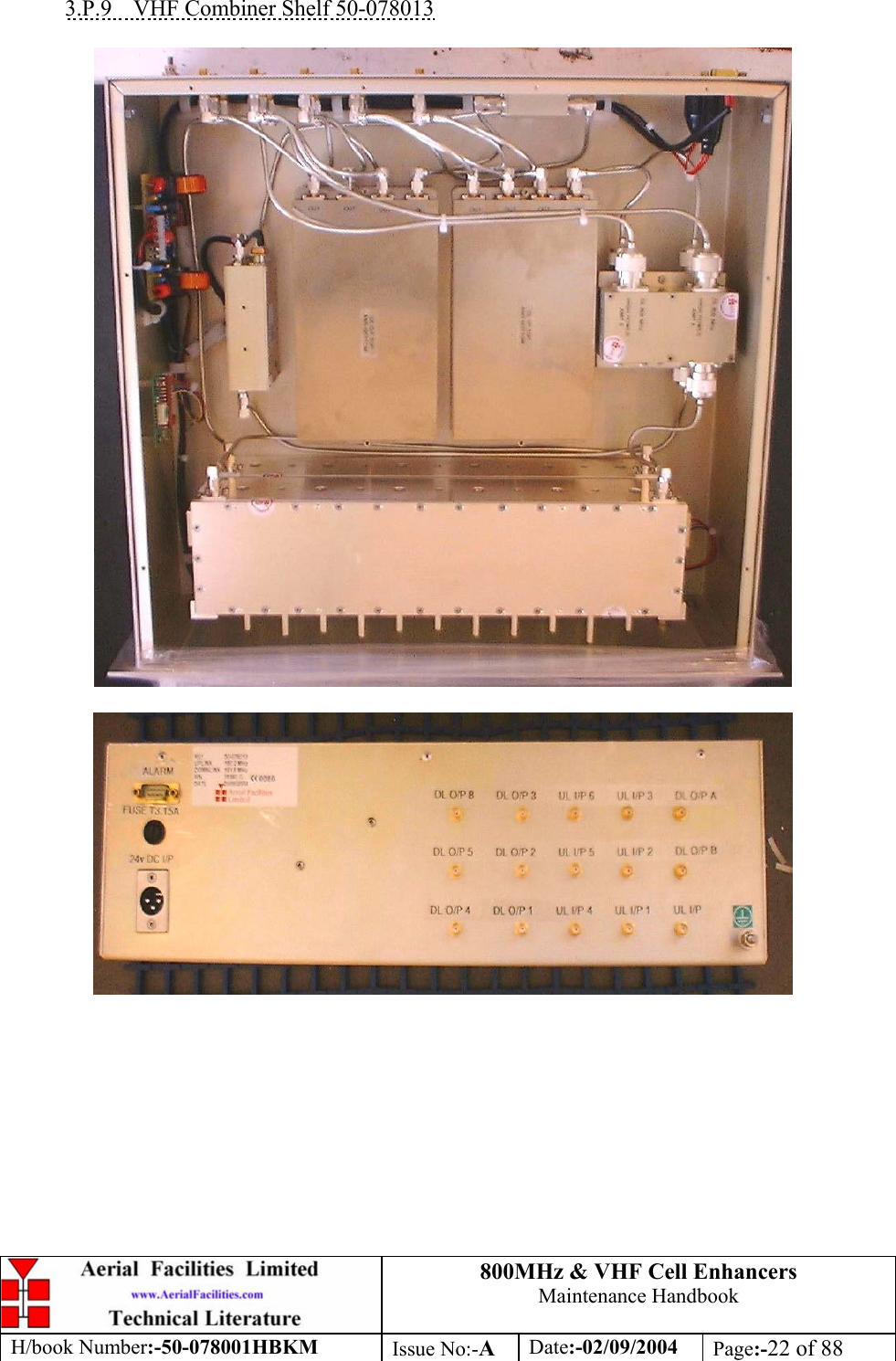
![800MHz & VHF Cell Enhancers Maintenance Handbook H/book Number:-50-078001HBKM Issue No:-A Date:-02/09/2004 Page:-42 of 88 3.4.11 VHF Air Interface Shelf 50-078012 Parts List AFL Part Nō. Part Description Qty. 01-002503 FILTER VHF H/B 6 SMA S 100W 2 05-002901 3dB BROADBAND SPLITTER SMA 1WATT 2 05-003401 4 WAY SPLITTER LOW POWER 1 07-005401 160-470MHz 3 WAY SPLITTER 2 11-004802 450MHz (10dB GAIN) LNA 12V. 1 12-002801 SINGLE CHANNEL ALARM BOARD STD 1 13-001803 DUAL DC/DC CONVERTER 24V-12V 1A 1 19-000826 2U,3U,4U 19" UNIT 400 DEEP LID 1 19-000921 3U 19" UNIT 400 DEEP CHASSIS + BKT 1 80-024203 TRANSMITTER HYBD COUPL.3 PORT 1 80-063627 3U FRONT PANEL FOR H/S 80-063920 1 91-030002 N ADAPTOR PANEL FEMALE:FEMALE 15 91-500001 POWER PLG 3 PIN PNL.MOUNT NC-X 1 91-510003 3 PIN R.ANGLE FREE SOC.NC-X. 1 91-700017 ICD 15 WAY 0.1' CONNECTOR 6 93-540035 1K3 0.25W 1% RES MRS25 M:F 2 96-110001 FUSE HOLDER 20 x 5mm6.3A 1 96-700034 LED RED 5mm IP67 INTEGRAL RES. 24V 1 96-700035 LED GREEN 5mm IP67 INTEGRAL RES 24V 1 97-400005 HANDLE TYPE H6802 3U [ALLOY] 2 3.4.12 VHF Combiner Shelf 50-078013 Parts List 01-002503 FILTER VHF H/B 6 SMA S 100W 2 05-002901 3dB BROADBAND SPLITTER SMA 1WATT 1 07-005401 160-470MHz 3 WAY SPLITTER 4 11-006002 LNA VHF 70-500MHz WITH RELAY 1 13-001803 DUAL DC/DC CONVERTER 24V-12V 1A 1 19-000826 2U,3U,4U 19" UNIT 400 DEEP LID 1 19-000921 3U 19" UNIT 400 DEEP CHASSIS + BKT 1 80-024203 TRANSMITTER HYBD COUPL.3 PORT 2 80-063627 3U FRONT PANEL FOR H/S 80-063920 1 91-030002 N ADAPTOR PANEL FEMALE:FEMALE 15 91-500001 POWER PLG 3 PIN PNL.MOUNT NC-X 1 91-510003 3 PIN R.ANGLE FREE SOC.NC-X. 1 93-540035 1K3 0.25W 1% RES MRS25 M:F 2 96-110001 FUSE HOLDER 20 x 5mm6.3A 1 96-700034 LED RED 5mm IP67 INTEGRAL RES. 24V 1 96-700035 LED GREEN 5mm IP67 INTEGRAL RES 24V 1 97-400005 HANDLE TYPE H6802 3U [ALLOY] 2](https://usermanual.wiki/PBE-Europe-as-Axell-Wireless/50-0780-VHF/User-Guide-484300-Page-42.png)
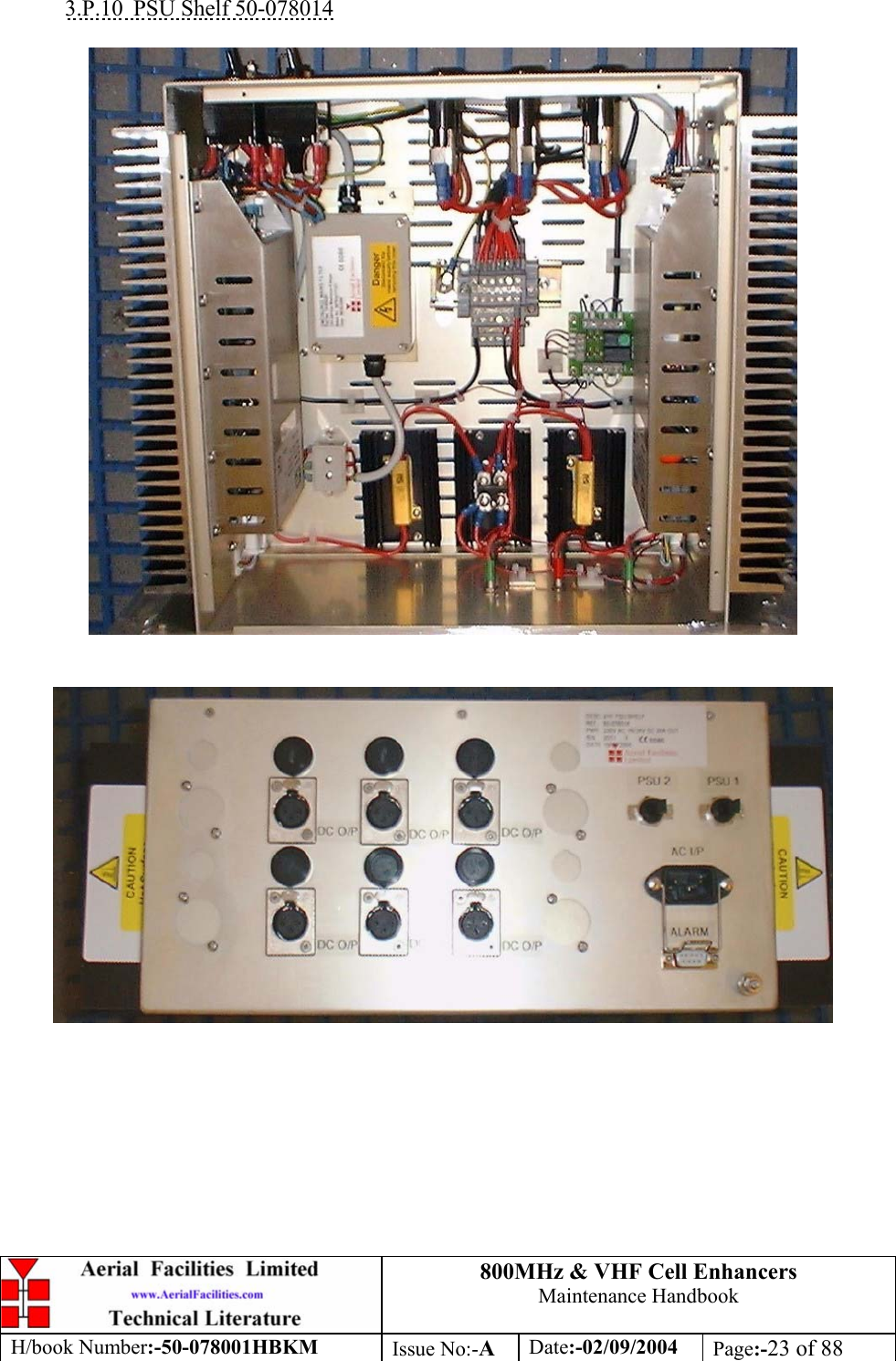
![800MHz & VHF Cell Enhancers Maintenance Handbook H/book Number:-50-078001HBKM Issue No:-A Date:-02/09/2004 Page:-43 of 88 3.4.13 VHF PSU Shelf 50-078014 Parts List AFL Part Nō. Part Description Qty. 13-003301 MAINS FILTER 8AMP ASSEMBLY 1 20-001602 24V RELAY BOARD 1 80-008920 DUAL PSU HEATSINK 2 80-008921 DUAL PSU CASE 1 80-008922 DUAL PSU LID 1 80-008925 DUAL PSU FRONT PANEL 1 80-020632 2U CHASSIS LID FIXING RAIL 4 91-500025 3 PIN RIGHT ANGLE FREE PLUG NC-X 6 91-510004 3 PIN PNL.MOUNT SOCKET NC-X 6 91-510035 3 WAY MATE N LOK PLUG HOUSING 2 91-520001 PWR MAINS INL FIXED/SOLD.TERMS 1 91-520005 MAINS LEAD (KETTLE, IEC) 1 91-520010 MAINS RETAINING CLIP 1 91-520032 MATE N LOK SOCKET CONTACT 20/14 AWG 6 91-600015 'D' 9 WAY PLUG S/B (NON FILTERED) 1 91-800014 3 WAY TERMINAL BLOCK 1 94-100004 STPS12045TV 60A DUAL DIODE 1 96-100001 20x5mm,10A FUSE HOLDER/CARRIER 6 96-300054 24V 17A PSU 400W (XP BCC) 2 96-600001 INSULATING BOOT LARGE 1 96-700035 LED GREEN 5mm IP67 INTEGRAL RES 24V 2 96-900017 AC TRIP SWITCH (3 AMP M.C.B.) 2 97-400002 HANDLE TYPE H6803 4U.[ALLOY] 2 3.4.14 VHF/800MHz Tx Multi-coupler Shelf 50-078015 Parts List AFL Part Nō. Part Description Qty. 05-002602 900MHz SPLITTER/COMBINER, 20W 1 05-002901 3dB BROADBAND SPLITTER SMA 1WATT 3 05-003401 4 WAY SPLITTER LOW POWER 1 05-003801 3WAY GEN.SPLIT 900MHz GEN.ASS 1 07-004101 70-1000MHz 3dB SPLITTER/COMBINER 1 07-005401 160-470MHz 3 WAY SPLITTER 2 07-005705 CROSSBAND CPLR XC 250/380 SMA 6 07-014002 6dB 170-2200MHz DIRECTIONAL COUPLE 2 19-001122K 5U CHASSIS KIT (450mm deep) 1 80-024203 TRANSMITTER HYBD COUPL.3 PORT 1 91-030002 N ADAPTOR PANEL FEMALE:FEMALE 15](https://usermanual.wiki/PBE-Europe-as-Axell-Wireless/50-0780-VHF/User-Guide-484300-Page-43.png)