PBE Europe as Axell Wireless 50-1272BDA VHF Bi Directional line amplifier type 50-127202 User Manual
Axell Wireless VHF Bi Directional line amplifier type 50-127202
User manual

VHF Headstation & In-Line Amplifiers
User Handbook
Handbook Nō.-50-127201FCC Issue No:-A
Date:-14/06/2005 Page:-1 of 45
VHF Headstation Bi-Directional
and In-line Amplifiers
User Handbook
For
Motorola Alaska
AFL Works Order Nō.: Q112856
AFL product part Nō.: 50-127201 (Bi-Directional Amplifier)
50-127202 (In-Line Amplifier)

VHF Headstation & In-Line Amplifiers
User Handbook
Handbook Nō.-50-127201FCC Issue No:-A
Date:-14/06/2005 Page:-2 of 45
Table of Contents
AMENDMENT LIST RECORD SHEET ...................................................................................................4
INTRODUCTION.........................................................................................................................................5
Scope ........................................................................................................................................................................... 5
Purpose ....................................................................................................................................................................... 5
Glossary of Terms...................................................................................................................................................... 6
Key to AFL RF Module Drawing Symbols ............................................................................................................. 7
1. SAFETY CONSIDERATIONS.........................................................................................................8
1.1 Earthing of Equipment ................................................................................................................................ 8
1.2 Electric Shock Hazard.................................................................................................................................. 8
1.3 RF Radiation Hazard ................................................................................................................................... 9
1.4 Chemical Hazard ........................................................................................................................................ 10
1.5 Emergency Contact Numbers.................................................................................................................... 10
2. OVERVIEW/SYSTEM DESCRIPTION .......................................................................................11
3. VHF AMPLIFIERS .........................................................................................................................12
3.1 VHF Headstation Bi-Directional Amplifier ............................................................................................. 12
3.1.1 VHF Headstation Bi-Directional Amplifier Description.......................................................................... 12
3.1.2 VHF Headstation Bi-Directional Amplifier Electrical Specifications...................................................... 12
3.1.3 VHF Headstation Bi-Directional Amplifier Mechanical Specifications................................................... 13
3.1.4 VHF Headstation Bi-Directional Amplifier System Diagram .................................................................. 14
3.1.5 VHF Headstation Bi-Directional Amplifier Parts List .............................................................................15
3.2 VHF In-Line Amplifier Description.......................................................................................................... 17
3.2.1 VHF In-Line Amplifier Electrical Specifications...................................................................................... 17
3.2.2 VHF In-Line Amplifier Mechanical Specifications................................................................................... 18
3.2.3 VHF In-Line Amplifier System Diagram .................................................................................................. 19
3.2.4 VHF In-Line Amplifier Parts List ............................................................................................................. 20
4. SUB-UNIT MODULES....................................................................................................................22
4.1 Bandpass Filter (01-002503) ...................................................................................................................... 22
4.1.1 Description ............................................................................................................................................... 22
4.1.2 Technical Specification............................................................................................................................. 22
4.2 VHF 30dB Coupler (07-000108)................................................................................................................ 23
4.2.1 Description ............................................................................................................................................... 23
4.2.2 Technical Specification............................................................................................................................. 23
4.3 ¼Watt 0- -30dB Switched Attenuator (10-000701)..................................................................................24
4.3.1 Switched Attenuators ................................................................................................................................ 24
4.3.2 Remote Attenuators (10-001201).............................................................................................................. 24
4.4 VHF/UHF Low Noise Amplifier (11-006002)........................................................................................... 25
4.4.1 Description ............................................................................................................................................... 25
4.4.2 Technical Specification............................................................................................................................. 25
4.4.3 LNA ‘D’ Connector Pin-out details.......................................................................................................... 25
4.5 10Watt Power Amplifier (12-002001) ....................................................................................................... 26
4.5.1 Description ............................................................................................................................................... 26
4.5.2 Technical Specification............................................................................................................................. 26
4.6 3 Stage Amplifier Alarm Board (12-002201)............................................................................................ 27
4.6.1 Description ............................................................................................................................................... 27
4.6.2 Technical Specification............................................................................................................................. 28
4.7 Single DC/DC Converter (13-001710)....................................................................................................... 29
4.7.2 Technical Specification............................................................................................................................. 29
4.8 Automatic Gain Control (17-001101, det. & 17-001201, atten.)............................................................. 30
4.8.1 Description ............................................................................................................................................... 30
4.8.2 Technical Specification............................................................................................................................. 31
4.9 Controller/Monitor Board (17-006801) .................................................................................................... 32

VHF Headstation & In-Line Amplifiers
User Handbook
Handbook Nō.-50-127201FCC Issue No:-A
Date:-14/06/2005 Page:-3 of 45
4.9.1 Description ............................................................................................................................................... 32
4.9.2 Drg. Nō. 17-006880, Controller/Monitor PCB Pin-Outs......................................................................... 33
4.10 24V Single Relay Board (80-008902) ........................................................................................................ 34
4.10.1 Description ........................................................................................................................................... 34
4.11 24V, 400W Power Supply Pack (96-300054) ............................................................................................ 34
4.11.1 Description ........................................................................................................................................... 34
4.11.2 Technical Specification......................................................................................................................... 34
4.12 STPS12045TV 60A Dual Diode Assembly................................................................................................ 35
4.12.1 Description ........................................................................................................................................... 35
4.13 MT2834ZDXK 56kBPS Modem (96-800003)........................................................................................... 35
4.13.1 Description ........................................................................................................................................... 35
5. INSTALLATION & COMMISSIONING......................................................................................36
5.1 Initial Installation Record.......................................................................................................................... 36
5.2 Antenna Installation & Gain Calculations ............................................................................................... 36
5.3 Antenna Isolation........................................................................................................................................ 37
5.4 General Remarks........................................................................................................................................ 38
5.5 Electrical Connections................................................................................................................................ 38
5.6 RF Connections........................................................................................................................................... 38
5.7 RS232 Setup ................................................................................................................................................ 39
6. MAINTENANCE .............................................................................................................................40
6.1 General Procedures .................................................................................................................................... 40
6.1.1 Quick Fault Checklist ............................................................................................................................... 40
6.1.2 Fault Finding............................................................................................................................................ 40
6.1.3 Downlink................................................................................................................................................... 41
6.1.4 Uplink ....................................................................................................................................................... 41
6.1.5 Fault repair............................................................................................................................................... 41
6.1.6 Checking service....................................................................................................................................... 42
6.1.7 Service Support......................................................................................................................................... 42
6.2 Tools & Test Equipment ............................................................................................................................ 42
6.3 Care of Modules.......................................................................................................................................... 43
6.3.1 General Comments ................................................................................................................................... 43
6.3.2 Module Removal (LNA’s, general procedure): ........................................................................................ 43
6.3.3 Module Replacement (general): ............................................................................................................... 43
6.3.4 Power Amplifiers ...................................................................................................................................... 43
6.3.5 Low Power Amplifier Replacement .......................................................................................................... 44
6.3.6 Module Transportation: ........................................................................................................................... 44
APPENDIX A INITIAL EQUIPMENT SET-UP CALCULATIONS.................................................45

VHF Headstation & In-Line Amplifiers
User Handbook
Handbook Nō.-50-127201FCC Issue No:-A
Date:-14/06/2005 Page:-4 of 45
AMENDMENT LIST RECORD SHEET
Issue
Nō.
Date Incorporated
by
Page No.’s
Amended
Reason for new issue
A 14/06/2005 CMH 1st Draft
Document Ref:-50-127201HBK

VHF Headstation & In-Line Amplifiers
User Handbook
Handbook Nō.-50-127201FCC Issue No:-A
Date:-14/06/2005 Page:-5 of 45
INTRODUCTION
Scope
This handbook is for use solely with the equipment identified by the AFL Part Number
shown on the front cover. It is not to be used with any other equipment unless specifically
authorised by Aerial Facilities Limited.
Purpose
The purpose of this handbook is to provide the user/maintainer with sufficient information to
service and repair the equipment to the level agreed. Maintenance and adjustments to any
deeper level must be performed by AFL, normally at the company’s repair facility in
Chesham, England.
This handbook has been prepared in accordance with BS 4884, and AFL’s Quality
procedures, which maintain the company’s registration to BS EN ISO 9001:2000 and to the
R&TTE Directive of the European Parliament. Copies of the relevant certificates and the
company Quality Manual can be supplied on application to the Quality Manager.
This document fulfils the relevant requirements of Article 6 of the R&TTE Directive.
Limitation of Information Notice
This manual is written for the use of technically competent operators/service persons. No
liability is accepted by AFL for use or misuse of this manual, the information contained
therein, or the consequences of any actions resulting from the use of the said information,
including, but not limited to, descriptive, procedural, typographical, arithmetical, or listing
errors.
Furthermore, AFL does not warrant the absolute accuracy of the information contained
within this manual, or it’s completeness, fitness for purpose, or scope.
AFL has a policy of continuous product development and enhancement, and as such,
reserves the right to amend, alter, update and generally change the contents, appearance and
pertinence of this document without notice.
All AFL products carry a twelve month warranty from date of shipment. The warranty is
expressly on a return to base repair or exchange basis and the warranty cover does not extend
to on-site repair or complete unit exchange.

VHF Headstation & In-Line Amplifiers
User Handbook
Handbook Nō.-50-127201FCC Issue No:-A
Date:-14/06/2005 Page:-6 of 45
Glossary of Terms
Repeater or
Cell Enhancer A Radio Frequency (RF) amplifier which can simultaneously
amplify and re-broadcast Mobile Station (MS) and Base
Transceiver Station (BTS) signals.
Band Selective Repeater A Cell Enhancer designed for operation on a range of
channels within a specified frequency band.
Channel Selective
Repeater A Cell Enhancer, designed for operation on specified
channel(s) within a specified frequency band. Channel
frequencies may be factory set or on-site programmable.
AC Alternating Current
AGC Automatic Gain Control
BBU Battery Backup Unit
BTS Base Transceiver Station
CEMS Coverage Enhanced Management System
C/NR Carrier-to-Noise Ratio
DC Direct Current
Downlink (D/L) RF signals Tx from the BTS to the Master Site
FO Fibre Optic
GND Ground
ID Identification Number
LED Light Emitting Diode
LNA Low Noise Amplifier
LPA Low Power Amplifier
MOU Master Optical Unit
M.S. Mobile Station
MTBF Mean Time Between Failures
N/A Not Applicable
N/C No Connection
OFR On Frequency Repeater
OIP3 Output Third Order Intercept Point = RFout +(C/I)/2
PA Power Amplifier
RF Radio Frequency
RSA Receiver/Splitter Amplifier
Rx Receiver
S/N Serial Number
Tx Transmitter
Uplink (U/L) RF signals transmitted from the MS to the BTS
VSWR Voltage Standing Wave Ratio
WDM Wave division multiplex
VHF Headstation & In-Line Amplifiers
User Handbook
Handbook Nō.-50-127201FCC Issue No:-A
Date:-14/06/2005 Page:-7 of 45
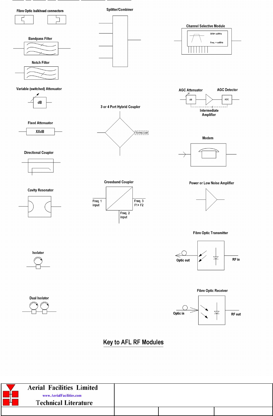
Key to AFL RF Module Drawing Symbols
VHF Headstation & In-Line Amplifiers
User Handbook
Handbook Nō.-50-127201FCC Issue No:-A
Date:-14/06/2005 Page:-8 of 45
1. SAFETY CONSIDERATIONS
1.1 Earthing of Equipment
Cell Enhancers supplied from the mains must be connected to grounded outlets and earthed
in conformity with appropriate local, national and international electricity supply and safety
regulations.
1.2 Electric Shock Hazard
Electrical shocks due to faulty mains driven power supplies.
Whilst ever potentially present in any electrical equipment, such a condition would be
minimised by quality installation practice and thorough testing at:
a) Original assembly
b) Commissioning
c) Regular intervals, thereafter.
All test equipment to be in good working order prior to its use. High current power supplies
can be dangerous because of the possibility of substantial arcing. Always switch off during
disconnection and reconnection.

VHF Headstation & In-Line Amplifiers
User Handbook
Handbook Nō.-50-127201FCC Issue No:-A
Date:-14/06/2005 Page:-9 of 45
1.3 RF Radiation Hazard
RF radiation, (especially at UHF frequencies) arising from transmitter outputs connected to
AFL’s equipment, must be considered a safety hazard.
This condition might only occur in the event of cable disconnection, or because a ‘spare’
output has been left unterminated. Either of these conditions would impair the system’s
efficiency. No investigation should be carried out until all RF power sources have been
removed. This would always be a wise precaution, despite the severe mismatch between the
impedance of an N type connector at 50Ω, and that of free space at 377Ω, which would
severely mitigate against the efficient radiation of RF power. Radio frequency burns could
also be a hazard, if any RF power carrying components were to be carelessly touched!
Antenna positions should be chosen to comply with requirements (both local & statutory)
regarding exposure of personnel to RF radiation. When connected to an antenna, the unit is
capable of producing RF field strengths, which may exceed guideline safe values especially if
used with antennas having appreciable gain. In this regard the use of directional antennas with
backscreens and a strict site rule that personnel must remain behind the screen while the RF
power is on, is strongly recommended.
Where the equipment is used near power lines, or in association with temporary masts not
having lightning protection, the use of a safety earth connected to the case-earthing bolt is
strongly advised.
VHF Headstation & In-Line Amplifiers
User Handbook
Handbook Nō.-50-127201FCC Issue No:-A
Date:-14/06/2005 Page:-10 of 45
1.4 Chemical Hazard
Beryllium Oxide, also known as Beryllium Monoxide, or Thermalox™, is sometimes used in
devices within equipment produced by Aerial Facilities Ltd. Beryllium oxide dust can be toxic
if inhaled, leading to chronic respiratory problems. It is harmless if ingested or by contact.
Products that contain beryllium are load terminations (dummy loads) and some power
amplifiers. These products can be identified by a yellow and black “skull and crossbones”
danger symbol (shown above). They are marked as hazardous in line with international
regulations, but pose no threat under normal circumstances. Only if a component containing
beryllium oxide has suffered catastrophic failure, or exploded, will there be any danger of the
formation of dust. Any dust that has been created will be contained within the equipment
module as long as the module remains sealed. For this reason, any module carrying the yellow
and black danger sign should not be opened. If the equipment is suspected of failure, or is at
the end of its life-cycle, it must be returned to Aerial Facilities Ltd for disposal.
To return such equipment, please contact the Quality Department, who will give you a
Returned Materials Authorisation (RMA) number. Please quote this number on the packing
documents, and on all correspondence relating to the shipment.
PolyTetraFluoroEthylene, (P.T.F.E.) and P.T.F.E. Composite Materials
Many modules/components in AFL equipment contain P.T.F.E. as part of the RF insulation
barrier.
This material should never be heated to the point where smoke or fumes are evolved. Any
person feeling drowsy after coming into contact with P.T.F.E. especially dust or fumes should
seek medical attention.
1.5 Emergency Contact Numbers
The AFL Quality Department can be contacted on:
Telephone +44 (0)1494 777000
Fax +44 (0)1494 777002
e-mail qa@aerial.co.uk

VHF Headstation & In-Line Amplifiers
User Handbook
Handbook Nō.-50-127201FCC Issue No:-A
Date:-14/06/2005 Page:-11 of 45
2. OVERVIEW/SYSTEM DESCRIPTION
The Headstation BDA and the In-Line amplifier equipment is designed to be air interfaced
towards the local BTS and provide a single output to an LCX antenna cable.
Automatic gain control in both paths (channel selective module in downlink path has
internal AGC) keeps the signal level from overloading the amplifiers should a mobile be
operated close to the LCX antenna.
Alarms are provided for each amplifier and these terminate in a RS232 compatible digital
PCB with an output suitable for an off-air modem (as in this case) or a local PC running a
suitable terminal emulation program. The RS232 PCB is also capable of varying the gain
in each path via remotely switchable 0-30dB attenuators. This is in addition to the 0-30dB
of attenuation which is available locally.
VHF Headstation & In-Line Amplifiers
User Handbook
Handbook Nō.-50-127201FCC Issue No:-A
Date:-14/06/2005 Page:-12 of 45
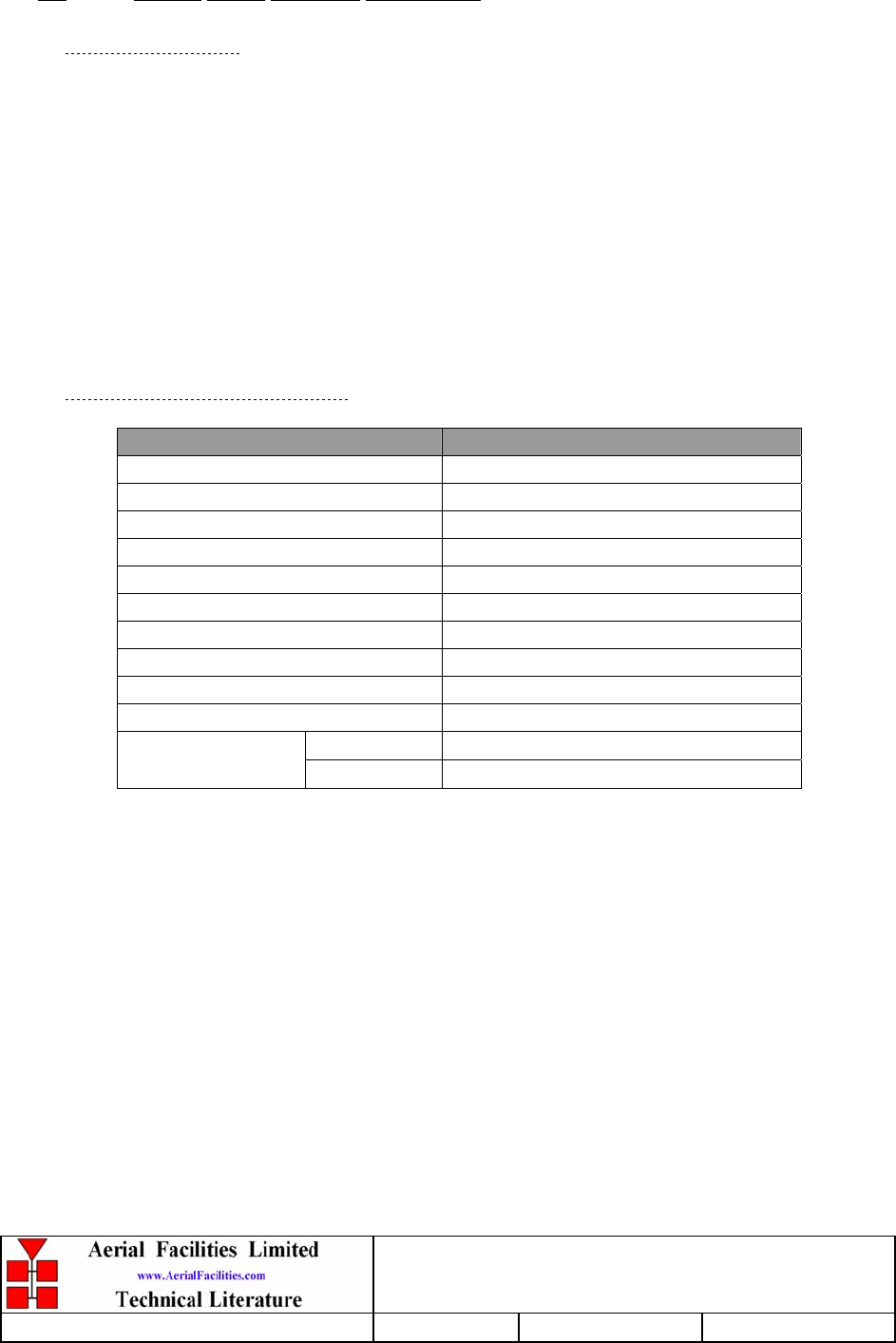
3. VHF AMPLIFIERS
3.1 VHF Headstation Bi-Directional Amplifier
3.1.1 VHF Headstation Bi-Directional Amplifier Description
See section 2.
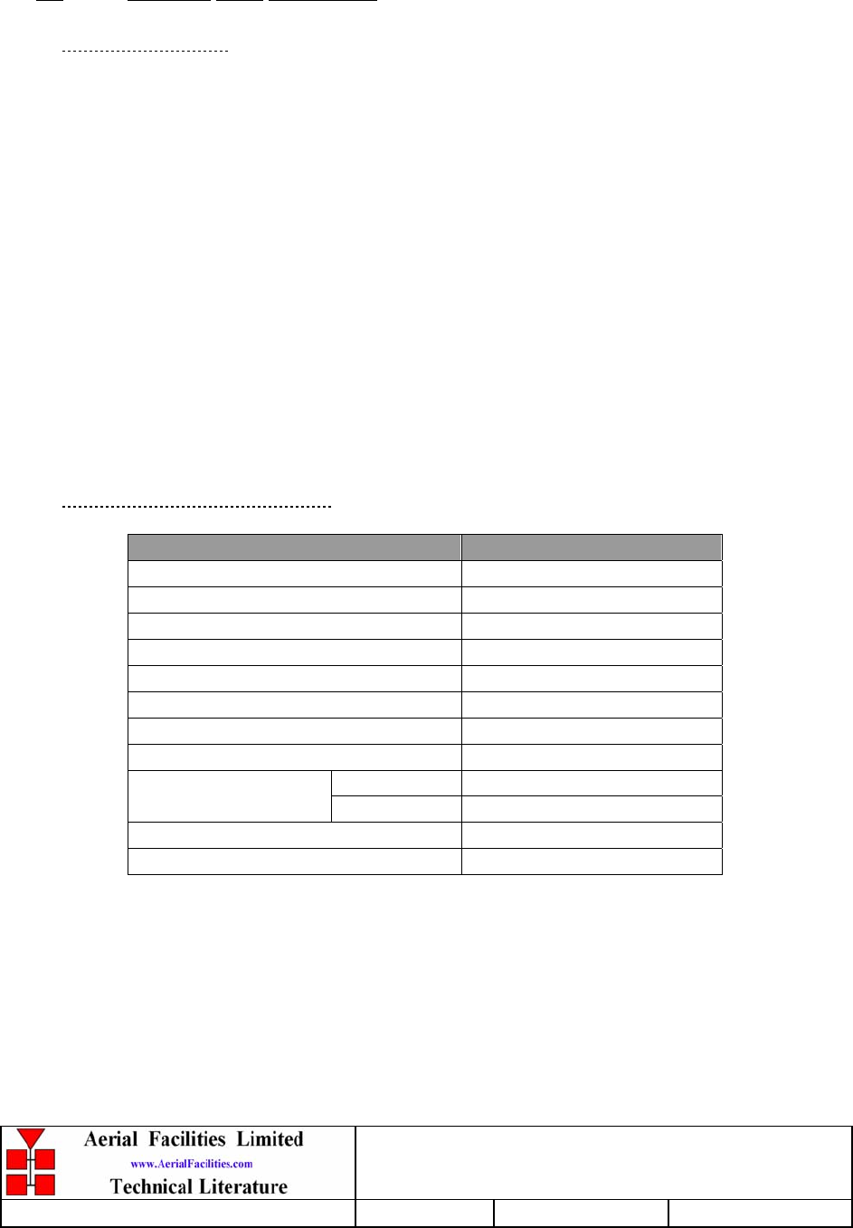
3.1.2 VHF Headstation Bi-Directional Amplifier Electrical Specifications
PARAMETER SPECIFICATION
137-143MHz (Downlink)
Frequency range: 154-156MHz (Uplink)
Uplink channel frequency: 155MHz ±0.75MHz
Passband ripple: ±1.5dB
Gain: >95dB
Gain Adjustment: 0 - 30dB (in 2dB steps)
Uplink Power: >10Watts
Downlink Power: >10Watts
Downlink OIP3: +50dBm
Uplink OIP3: +45dBm
Downlink 1dB compression point: +38dBm
Uplink 1dB compression point: +35dBm
In-Band Spurious noise: <-36dBm (30kHz B/W)
Downlink: +37dBm
AGC: Uplink: +34dBm
Noise Figure: <6dB
VSWR: better than 1.5:1
RF Connectors: N type, female
operational: -10°C to +60°C
Temperature range: storage: -40°C to +70°C
1 Amplifiers
2 PSU
3 Door Intrusion
Alarms Fitted:
(volt-free contacts/TTL)
4 Over temperature

VHF Headstation & In-Line Amplifiers
User Handbook
Handbook Nō.-50-127201FCC Issue No:-A
Date:-14/06/2005 Page:-13 of 45
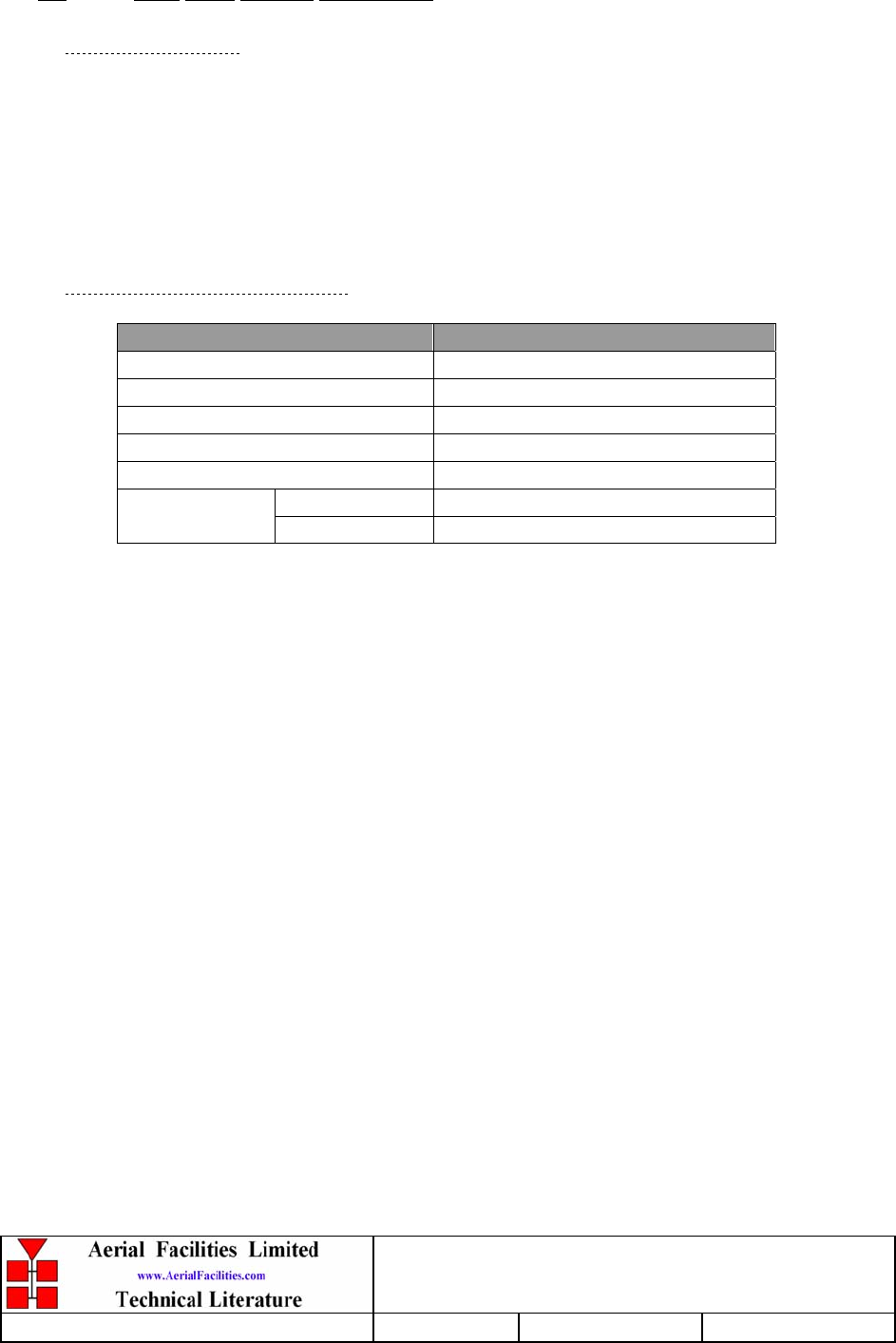
3.1.3 VHF Headstation Bi-Directional Amplifier Mechanical Specifications
PARAMETER SPECIFICATION
Height: 620mm
Width: 620mm
Case size
Depth: 250mm
(excluding heatsinks, connectors, handles and feet)
Fixings: 4 holes on 670(w) x 558(h)mm
Operational: -10°C to +60°C
Temperature range:
Storage: -40°C to +70°C
Weight: >30kg (two-man-lift)
RF Connectors: N type female
Environmental Protection: IP65 (with door closed and all ports terminated)
Case: Painted to RAL 7035
Heatsinks: Matt black (where fitted)
Finish:
Handles: Black technopolymer
Supply Cable: Unit supplied with suitable supply input leads with
connector and appropriate length of cable
VHF Headstation & In-Line Amplifiers
User Handbook
Handbook Nō.-50-127201FCC Issue No:-A
Date:-14/06/2005 Page:-14 of 45
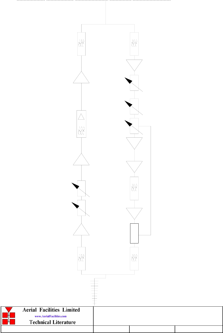
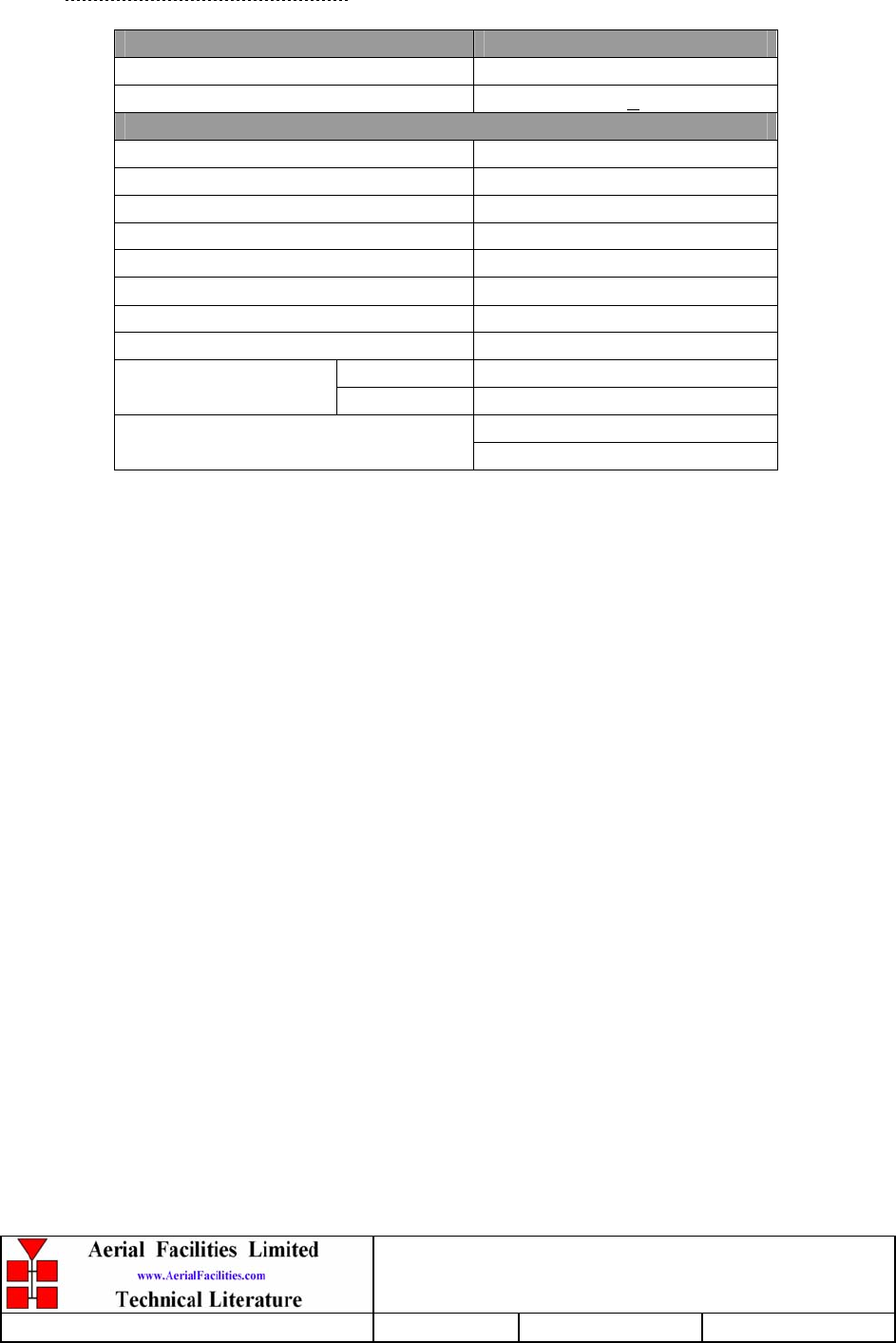
3.1.4 VHF Headstation Bi-Directional Amplifier System Diagram
dB
dBdB
137-143MHz 137-143MHz 137-143MHz
154-156MHz 154-156MHz155MHz(1.5MHz)
01-002603 11-006002 11-006002
12-002001 11-006002 11-006002 11-006002
10-000703
17-011402 12-002001
01-002603 01-002603 01-002603
01-002603
10-000703
dB
10-001201
dB
10-001201
17-001101
17-001201

VHF Headstation & In-Line Amplifiers
User Handbook
Handbook Nō.-50-127201FCC Issue No:-A
Date:-14/06/2005 Page:-15 of 45
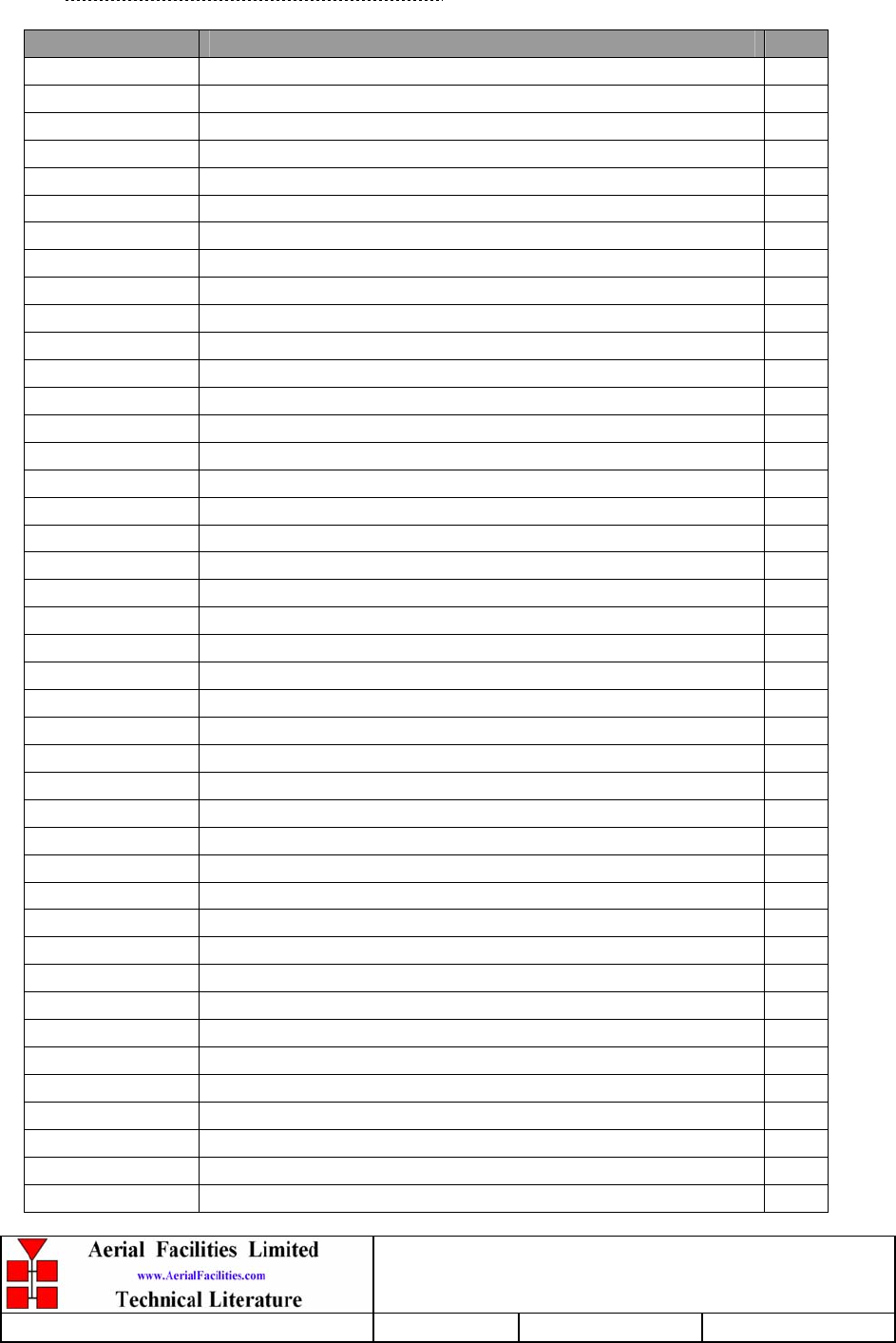
3.1.5 VHF Headstation Bi-Directional Amplifier Parts List
AFL Part Nō. Part Description Qty.
01-002603 FILTER VHF H/B 8 SMA S 100W 5
07-001801 POWER MONITOR VHF SINGLE DC OUTPUT 2
10-000703 1/4W0-30dB SWITCHED ATTENUATOR 2
10-001201 ATTEN.SWTCH REMOTE D TYPE 30dB 2
11-006002 LNA VHF 70-500MHz WITH RELAY 5
12-002001 PWR AMP 10W 100-250MHz SMA CON 2
12-002201 3 STAGE AMPLIFIER ALARM BOARD 2
12-002220 3 STAGE ALARM PCB COVER 2
12-002826 ALARM BOARD ACRYLIC LENS 2
13-001704 VOLTAGE REGULATOR BOARD 9.0V 1
13-001710 VOLTAGE REGULATOR BOARD 5.0V 1
13-003301 MAINS FILTER 8AMP ASSEMBLY 1
17-000526 CE 10/20W HEATSINK THERMAL GASKET 3
17-001101 CELL ENHANCER AGC DETECTOR/AMP ASS 1
17-001201 C/E AGC UNIT ATTENUATOR ASSY 1
17-002020K 620x620x250 ENCLOSURE 2 H/S KIT 1
17-006801 CONTROLLER/MONITOR BOARD, 24V 1
17-006820 COVER FOR CONTROLLER/MON PCB 1
17-011402 CHAN MOD 150-170 MHz 1.5 MHz BW 1
20-001602 24V RELAY BOARD 1
80-032320 10W PA HEATSINK 2
80-310420 BCC 400W POWER SUPPLY HEATSINK 1
90-100003 MAINS LEAD '6 AMP' 1
90-300045 BATT.BACKUP LEADS (2 1
90-400013 CE/BBU ALARM LINK LEAD 4 CORE 1
91-030002 N ADAPTOR PANEL FEMALE:FEMALE 2
91-100003 SMA PLUG ELBOW UT-141 8
91-130001 SMA ADAPT 'T' ALL FEMALE 3 GHZ 2
91-500011 PWR 3POLE PNL PLUG SEALED IP68 1
91-500013 PWR 2POLE PNL PLUG SEALED IP68 1
91-500015 PWR CON CAP SEALED with INT. THREAD 3
91-510035 3 WAY MATE N LOK PLUG HOUSING 1
91-510036 PWR 6POLE PANEL SOCKET SEALED IP68 1
91-520032 MATE N LOK SOCKET CONTACT 20/14 AWG 3
91-600014 'D' 9 WAY SOCKET S/B (NON FILTERED) 6
91-620001 'D' 25 WAY SOCKET S/B TERM 1
91-620006 'D' 25 WAY CONNECTOR SHELL 1
91-700008 ICD 5 WAY 0.1' IDC CONNECTOR 4
91-700017 ICD 15 WAY 0.1' CONNECTOR 5
92-120009 M20 IP68 CABLE GLAND 1
94-100004 STPS12045TV 60A DUAL DIODE 1
96-300054 24V 17A PSU 400W (XP BCC) 2

VHF Headstation & In-Line Amplifiers
User Handbook
Handbook Nō.-50-127201FCC Issue No:-A
Date:-14/06/2005 Page:-16 of 45
96-700034 LED RED 5mm IP67 1
96-700035 LED GREEN 5mm IP67 1
96-800003 MT2834ZDXK 56kBPS MODEM WORLD 1
96-900017 AC TRIP SWITCH (3 AMP M.C.B.) 1
96-920011 PROXIMITY SWITCH 1
96-920012 PROXIMITY SWITCH MAGNET 1
97-300010 C/E SUPPLY INPUT COVER 2
97-300028 DC BOX 24V ATO TYPE 2 ASSEMBLY 1
97-900004 RUBBER FOOT FOR CELL ENHANCERS 4
VHF Headstation & In-Line Amplifiers
User Handbook
Handbook Nō.-50-127201FCC Issue No:-A
Date:-14/06/2005 Page:-17 of 45
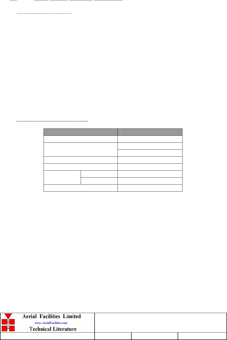
3.2 VHF In-Line Amplifier Description
The In-line amplifier is almost identical to the Headstation BDA except it has lower gain.
3.2.1 VHF In-Line Amplifier Electrical Specifications
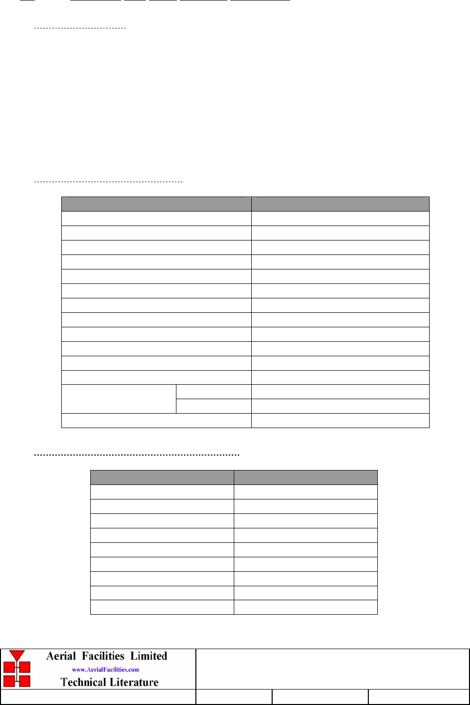
PARAMETER SPECIFICATION
137-143MHz (Downlink)
Frequency range: 154-156MHz (Uplink)
Uplink channel frequency: 155MHz ±0.75MHz
Passband ripple: ±1.5dB
Gain: >30dB
Gain Adjustment: 0 - 30dB (in 2dB steps)
Uplink Power: >10Watts
Downlink Power: >10Watts
Downlink OIP3: +50dBm
Uplink OIP3: +45dBm
Downlink 1dB compression point: +38dBm
Uplink 1dB compression point: +35dBm
In-Band Spurious noise: <-36dBm (30kHz B/W)
Downlink: +37dBm
AGC: Uplink: +34dBm
Noise Figure: <6dB
VSWR: better than 1.5:1
RF Connectors: N type, female
operational: -10°C to +60°C
Temperature range: storage: -40°C to +70°C
1 Amplifiers
2 PSU
3 Door Intrusion
Alarms Fitted:
(volt-free contacts/TTL)
4 Over temperature
VHF Headstation & In-Line Amplifiers
User Handbook
Handbook Nō.-50-127201FCC Issue No:-A
Date:-14/06/2005 Page:-18 of 45
3.2.2 VHF In-Line Amplifier Mechanical Specifications
PARAMETER SPECIFICATION
Height: 620mm
Width: 620mm
Case size
Depth: 250mm
(excluding heatsinks, connectors, handles and feet)
Fixings: 4 holes on 670(w) x 558(h)mm
Operational: -10°C to +60°C
Temperature range:
Storage: -40°C to +70°C
Weight: >30kg (two-man-lift)
RF Connectors: N type female
Environmental Protection: IP65 (with door closed and all ports terminated)
Case: Painted to RAL 7035
Heatsinks: Matt black (where fitted)
Finish:
Handles: Black technopolymer
Supply Cable: Unit supplied with suitable supply input leads with
connector and appropriate length of cable
VHF Headstation & In-Line Amplifiers
User Handbook
Handbook Nō.-50-127201FCC Issue No:-A
Date:-14/06/2005 Page:-19 of 45
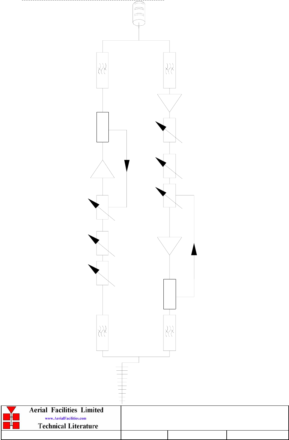
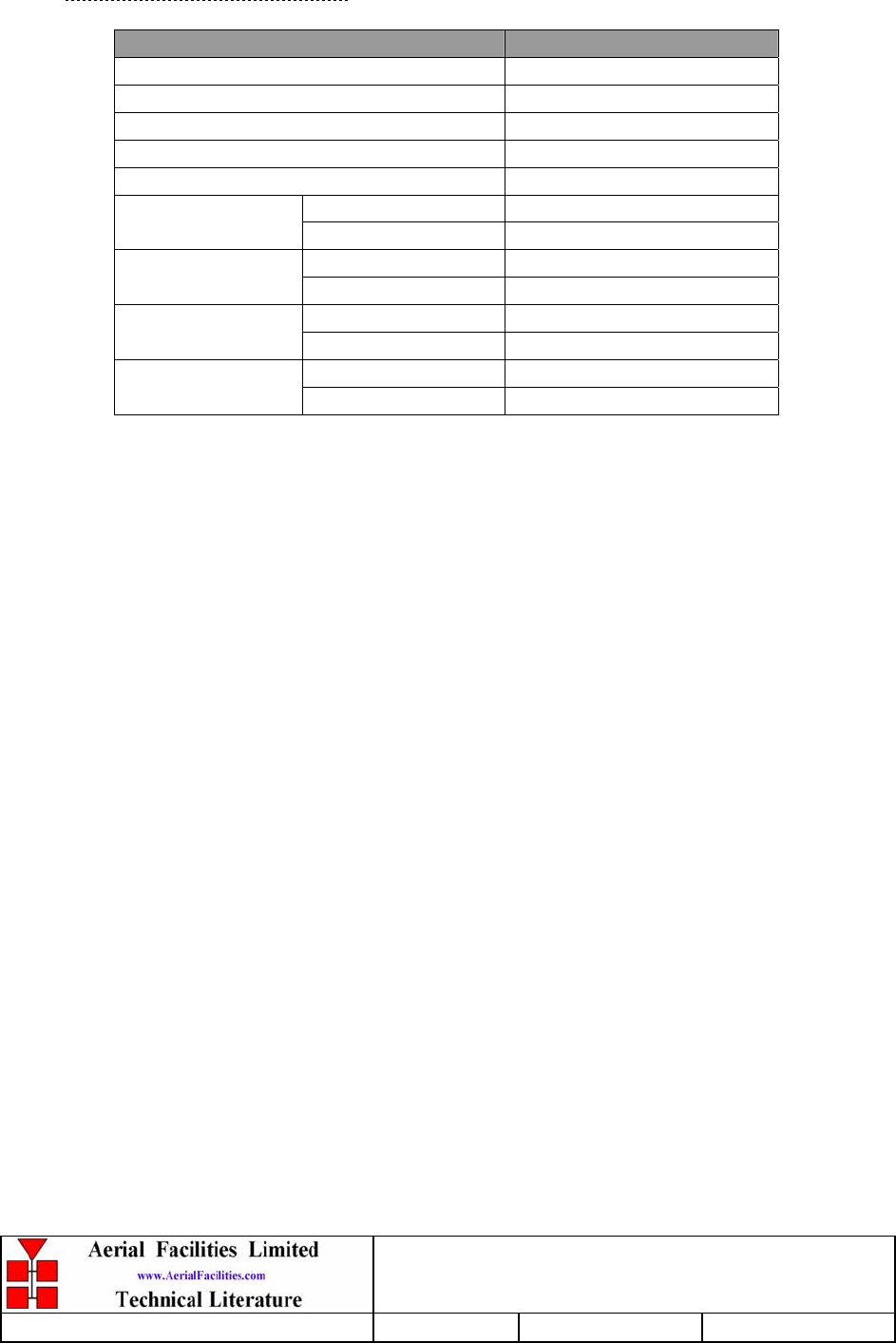
3.2.3 VHF In-Line Amplifier System Diagram
dB
dBdB
137-143MHz 137-143MHz
154-156MHz 154-156MHz
12-002001 11-006002
10-000703
12-002001
10-000703
dB
dB
10-001201
17-001101
17-001201
dB
17-001101
10-001201 17-001201
01-002503
01-002503 01-002503
01-002503
VHF Headstation & In-Line Amplifiers
User Handbook
Handbook Nō.-50-127201FCC Issue No:-A
Date:-14/06/2005 Page:-20 of 45
3.2.4 VHF In-Line Amplifier Parts List
AFL Part Nō. Part Description Qty.
01-002503 FILTER VHF H/B 6 SMA S 100W 4
07-001801 POWER MONITOR VHF SINGLE DC OUTPUT 2
10-000703 1/4W0-30dB SWITCHED ATTENUATOR 2
10-001201 ATTEN.SWTCH REMOTE D TYPE 30dB 2
11-006002 LNA VHF 70-500MHz WITH RELAY 1
12-002001 PWR AMP 10W 100-250MHz SMA CON 2
12-002201 3 STAGE AMPLIFIER ALARM BOARD 2
12-002220 3 STAGE ALARM PCB COVER 2
12-002826 ALARM BOARD ACRYLIC LENS 2
13-001704 VOLTAGE REGULATOR BOARD 9.0V 1
13-001710 VOLTAGE REGULATOR BOARD 5.0V 1
13-003301 MAINS FILTER 8AMP ASSEMBLY 1
17-000526 CE 10/20W HEATSINK THERMAL GASKET 3
17-001101 CELL ENHANCER AGC DETECTOR/AMP ASS 2
17-001201 C/E AGC UNIT ATTENUATOR ASSY 2
17-006801 CONTROLLER/MONITOR BOARD, 24V 1
17-006820 COVER FOR CONTROLLER/MON PCB 1
17-009020K 620x420x250 ENCLOSURE 3 H/S KIT 1
20-001602 24V RELAY BOARD 1
80-032320 10W PA HEATSINK (NEEDS 17-000526) 2
80-310420 BCC 400W POWER SUPPLY HEATSINK 1
90-100003 MAINS LEAD '6 AMP' 1
90-300045 BATT.BACKUP LEADS (2 1
90-400013 CE/BBU ALARM LINK LEAD 4 CORE 1
91-030002 N ADAPTOR PANEL FEMALE:FEMALE 2
91-100003 SMA PLUG ELBOW UT-141 8
91-130001 SMA ADAPT 'T' ALL FEMALE 3 GHZ 2
91-500011 PWR 3POLE PNL PLUG SEALED IP68 1
91-500013 PWR 2POLE PNL PLUG SEALED IP68 1
91-500015 PWR CON CAP SEALED with INT. THREAD 3
91-510035 3 WAY MATE N LOK PLUG HOUSING 1
91-510036 PWR 6POLE PANEL SOCKET SEALED IP68 1
91-520032 MATE N LOK SOCKET CONTACT 20/14 AWG 3
91-600014 'D' 9 WAY SOCKET S/B (NON FILTERED) 2
91-700008 ICD 5 WAY 0.1' IDC CONNECTOR 4
91-700017 ICD 15 WAY 0.1' CONNECTOR 4
92-120009 M20 IP68 CABLE GLAND 1
96-300054 24V 17A PSU 400W (XP BCC) 2
96-700034 LED RED 5mm IP67 INTEGRAL RES. 24V 1
96-700035 LED GREEN 5mm IP67 INTEGRAL RES 24V 1
96-800003 MT2834ZDXK 56kBPS MODEM WORLD 1
96-900017 AC TRIP SWITCH (3 AMP M.C.B.) 1

VHF Headstation & In-Line Amplifiers
User Handbook
Handbook Nō.-50-127201FCC Issue No:-A
Date:-14/06/2005 Page:-21 of 45
96-920011 PROXIMITY SWITCH 1
96-920012 PROXIMITY SWITCH MAGNET 1
97-300010 C/E SUPPLY INPUT COVER 2
97-300028 DC BOX 24V ATO TYPE 2 ASSEMBLY 1
97-900004 RUBBER FOOT FOR CELL ENHANCERS 4
VHF Headstation & In-Line Amplifiers
User Handbook
Handbook Nō.-50-127201FCC Issue No:-A
Date:-14/06/2005 Page:-22 of 45
4. SUB-UNIT MODULES
4.1 Bandpass Filter (01-002503)
4.1.1 Description
The bandpass filters are multi-section designs with a bandwidth dependent upon the
passband frequencies, (both tuned to customer requirements). The response shape is basically
Chebyshev with a passband design ripple of 0.1dB. The filters are of helical design, and are
carefully aligned during manufacture in order to optimise the insertion loss, VSWR and
intermodulation characteristics of the unit. The tuned elements are silver-plated to reduce
surface ohmic losses and maintain a good VSWR figure and 50Ω load at the input and output
ports.
Being passive devices, the bandpass filters should have an extremely long operational life
and require no maintenance. Should a filter be suspect, it is usually most time efficient to
replace the module rather than attempt repair or re-tuning.
No adjustments should be attempted without full network sweep analysis facilities to
monitor both insertion loss and VSWR simultaneously.
4.1.2 Technical Specification
SPECIFICATION PARAMETER
Response type: Chebyshev
Frequency range: 135 – 250MHz
Bandwidth: 3.5MHz (tuned to spec.)
Nō. of sections: 6
Insertion loss: 1.2dB
VSWR: Better than 1.2:1
Connectors: SMA
Power Handling: 100W maximum
operate: -10°C to +60°C
Temperature range: store: -20°C to +70°C
Weight: 3 kg
Size: 384 x 82.5 x 56.4mm
VHF Headstation & In-Line Amplifiers
User Handbook
Handbook Nō.-50-127201FCC Issue No:-A
Date:-14/06/2005 Page:-23 of 45
4.2 VHF 30dB Coupler (07-000108)
4.2.1 Description
The purpose of these couplers is to ‘tap off’ known portions (usually 15-30dB) of RF signal
from transmission lines, either resistively or by induction, and to combine them, for example
through splitter units for different purposes (alarms/monitoring etc.), whilst maintaining an
accurate 50Ω load to all ports/interfaces throughout the specified frequency range.
In this instance, one of these couplers is used at each antenna port, with its’ DC output taken
to the RS232 PCB in order to monitor any power output loss to the antenna.
4.2.2 Technical Specification
PARAMETER SPECIFICATION
Frequency Range: 140 – 160MHz
Bandwidth: 20MHz (typical)
Insertion Loss: <1.0dB
Rejection: >20dB
30dB Coupling: ±1dB (in band)
operation: -10%C to +60%C Temperature
Range: storage: -20%C to +70%C

VHF Headstation & In-Line Amplifiers
User Handbook
Handbook Nō.-50-127201FCC Issue No:-A
Date:-14/06/2005 Page:-24 of 45
4.3 ¼Watt 0- -30dB Switched Attenuator (10-000701)
4.3.1 Switched Attenuators
The AFL switched attenuators are available in two different types; 0 – 30dB in 2 dB steps (as
in this case), or 0 – 15dB in 1 dB steps. The attenuation is simply set using the four miniature
toggle switches on the top of each unit. Each switch is clearly marked with the attenuation it
provides, and the total attenuation in line is the sum of the values switched in. They are
designed to maintain an accurate 50Ω impedance over their operating frequency at both input
and output.
4.3.2 Remote Attenuators (10-001201)
The remote attenuators perform exactly the same RF function as the manually switched
version. The only difference being, in the remote version, binary signals from the
controller/monitor PCB are fed to the attenuator via a multi-wire (4-bit) digital signal to
relays that control which attenuator network to switch into circuit. The remote attenuators
are entirely passive devices and should need no regular maintenance.
VHF Headstation & In-Line Amplifiers
User Handbook
Handbook Nō.-50-127201FCC Issue No:-A
Date:-14/06/2005 Page:-25 of 45
4.4 VHF/UHF Low Noise Amplifier (11-006002)
4.4.1 Description
The 21dB gain low noise amplifier used is a double stage solid-state low-noise amplifier.
Class A circuitry is used throughout the unit to ensure excellent linearity over a very wide
dynamic range. The two active devices are very moderately rated to provide a long, trouble-
free working life. There are no adjustments on this amplifier, and in the unlikely event of
failure then the entire amplifier should be replaced. The amplifier features a dedicated, in-
built alarm monitoring system based on class A DC biasing levels whose output is a volts-free
relay contact pair that may be integrated into an existing system via the 9-way D-type
interface.
4.4.2 Technical Specification
PARAMETER SPECIFICATION
Frequency range: 70 – 500MHz
Bandwidth: <430MHz
Gain: 21dB (typical)
1dB Compression Point: +20dB (typical)
3rd order intercept: +33dB (typical)
Input return loss: >14dB
Output return loss: >20dB
VSWR: Better than 1.5:1
Noise figure: <2.7dB
Connectors: SMA female
Supply: 230 - 260mA @ 10 to 24V DC
Size: 88 x 50 x 34mm (ex. connectors)
operational: -10°C to +60°C
Temperature range: storage: -20°C to +70°C
Weight: 0.26kg
4.4.3 LNA ‘D’ Connector Pin-out details
Connector pin Signal
1 +Ve input (10-24V)
2 GND
3 Alarm Relay O/P bad
4 Alarm Relay common
5 Alarm Relay good
6 No connection
7 TTL voltage set
8 TTL alarm/0V (good)
9 O/C good/0V bad
VHF Headstation & In-Line Amplifiers
User Handbook
Handbook Nō.-50-127201FCC Issue No:-A
Date:-14/06/2005 Page:-26 of 45
4.5 10Watt Power Amplifier (12-002001)
4.5.1 Description
The power amplifier fitted to this unit is a multi-stage, solid state power amplifier. Class A
circuitry is employed throughout the device to ensure excellent linearity over a wide
dynamic frequency range. All the semi-conductor devices are very conservatively rated to
ensure low device junction temperatures and a long, trouble free working lifetime.
The power amplifier should require no maintenance over its operating life. Under no
circumstances should the cover be removed or the side adjustments disturbed unless it is
certain that the amplifier has failed; since it is critically aligned during manufacture and
any re-alignment will require extensive test equipment.
4.5.2 Technical Specification
PARAMETER SPECIFICATION
Frequency range: 100 - 250MHz (tuned to spec.)
Bandwidth: 20MHz (typical, tuned to spec.)
Maximum RF output: >10Watts
Gain: >50dB
1dB compression point: +40dBm
3rd order intercept point: +50dBm
VSWR: better than 1.5:1
Connectors: SMA female
Supply: 2.5Amps @ 24V DC
Weight: 1kg (excluding heatsink)
operational: -10°C to +60°C Temperature
range: storage: -20°C to +70°C

VHF Headstation & In-Line Amplifiers
User Handbook
Handbook Nō.-50-127201FCC Issue No:-A
Date:-14/06/2005 Page:-27 of 45
4.6 3 Stage Amplifier Alarm Board (12-002201)
4.6.1 Description
Amplifier Alarm Boards are fitted to monitor the bias conditions of AFL Class A amplifiers
which remain constant in normal operation. Any departure from normal bias conditions is a
result of device failure, excess temperature, over-driving or oscillation (excessive power).
In normal operation, the Class A bias circuit of the amplifier develops a constant voltage of
1.20V across the collector current setting resistor. The Amplifier Alarm Board is a window
comparator device, which is adjusted to sense a departure from this condition. Several
different alarm outputs are provided to simplify interfacing, (Relay Contact, Open
Collector, and TTL Logic Levels)
The basic version of the Alarm Board (12-002801) monitors a single amplifier stage. A
three-stage version (12-002201) is used on complex amplifiers where three separate
comparators have their outputs logically combined to a common output stage. Failure of
any one stage will activate the alarms.
Note that the alarm board has a green Light Emitting Diode located near to the centre of the
printed circuit board, which is illuminated on ‘Good’, and extinguished on ‘Alarm’. It is
therefore a simple matter to identify an active module failure, by searching for an Alarm
Board which has its green LED extinguished. A simple test of the alarm board is possible by
shorting across the monitor inputs, pins 1 and 2, 3 and 4 or across pins 5 and 6. This last
monitor input is inactive if the board has been converted to a two way alarm board. (Refer
to relevant amplifier alarm wiring diagram.)
1) Volt-free change over relay contacts.
2) Open collector NPN transistor pulls low on alarm.
3) TTL driver.
The use of precision voltage sources and resistors has eliminated the need for initial
adjustment or calibration, and the board will function correctly with a wide variation in
power supply voltage (8 to 30 volts, nominal supply is 12 or 24Volts).
There are two selectable link options on the three-way board:
LINK1 - Removed to convert to two-way alarm board.
LINK2 - Removed to isolate 0V from chassis earth.
The one way alarm board only has the 0V isolation link (LINK2) fitted.
VHF Headstation & In-Line Amplifiers
User Handbook
Handbook Nō.-50-127201FCC Issue No:-A
Date:-14/06/2005 Page:-28 of 45
4.6.2 Technical Specification
PARAMETER SPECIFICATION
Operating voltage: 8 to 30V (floating earth)
Alarm Threshold: Vcc - 1.20 volt +15%
Alarm output relay contacts:
Max. switch current: 1.0Amp
Max. switch volts: 120Vdc/60VA
Max. switch power: 24W/60VA
Min. switch load: 10.0µA/10.0mV
Relay isolation: 1.5kV
Mechanical life: >2x10⁷ operations
Relay approval: BT type 56
Connector details: 15-way 0.1" pitch
operational: -10°C to +60°C
Temperature range: storage: -20°C to +70°C
74 x 56mm (3 stage)
PCB Size: 54 x 56mm (1 stage)
VHF Headstation & In-Line Amplifiers
User Handbook
Handbook Nō.-50-127201FCC Issue No:-A
Date:-14/06/2005 Page:-29 of 45
4.7 Single DC/DC Converter (13-001710)
4.7.1 Description
This unit it is used to derive a fixed voltage power supply rail from some higher voltage.
Typically, it is used to derive 5V, 8V, 12V or 15V from a 24V input.
The circuit is based upon an LM317 variable voltage regulator, which is capable of
supplying a maximum of 1.5A output current. Note that at full output current the
dissipation of the device must remain in limits, bearing in mind the voltage which is being
dropped across it. The maximum allowable dissipation will also depend on the efficiency
of the heatsink on which the device is mounted.
The output voltage of the unit is programmed by the resistive divider which is fitted
between the output terminal, the reference terminal and ground. R1 is the reference
programming resistor and is fixed in all versions. R2 is fitted on 12V versions while R3,
(which is in parallel with R2) is fitted on 8V and 5V versions.
4.7.2 Technical Specification
PARAMETER SPECIFICATION
Operating Voltage: 21 – 27V DC
5.0V (13-001710)
Output Voltages: 9.0V (13-001704)
Output Current: 1.0A (maximum per o/p)
Connections: Screw Terminal Block
operational: -10%C to +60%C Temperature
range: storage: -20%C to +70%C
PCB Size: 47 x 30mm

VHF Headstation & In-Line Amplifiers
User Handbook
Handbook Nō.-50-127201FCC Issue No:-A
Date:-14/06/2005 Page:-30 of 45
4.8 Automatic Gain Control (17-001101, det. & 17-001201, atten.)
4.8.1 Description
The equipment is fitted with an Automatic Gain Control (AGC) system. This is generally
fitted in the Uplink path (not usually needed in the downlink path, as the signal here is at an
almost constant level), to avoid overloading the amplifiers (with the associated performance
degradation) should a mobile be operated very close to the unit.
The AFL Automatic Gain Control system consists of two units, a detector/amplifier and an
attenuator. The detector/amplifier unit is inserted in the RF path on the output of the power
amplifier, and the attenuator is situated in the RF path between the 1st and 2nd stages of
amplification.
Normally the attenuator is at minimum attenuation. The detector/amplifier unit monitors the
RF level being delivered by the power amplifier, and when a certain threshold is reached it
begins to increase the value of the attenuator to limit the RF output to the (factory set)
threshold. Therefore overloading of the power amplifier is avoided.
The factory set threshold is 1dB below the Enhancer 1dB compression point. Some
adjustment of this AGC threshold level is possible, a 10dB range is mostly achieved. It is not
recommended under any circumstances to adjust the AGC threshold to a level greater than
the 1dB compression point as system degradation will occur.
The detector comprises of a 50Ω transmission line with a resistive tap which samples a small
portion of the mainline power. The sampled signal is amplified and fed to a conventional
half wave diode rectifier, the output of which is a DC voltage proportional to the RF input
signal.
This DC voltage is passed via an inverting DC amplifier with integrating characteristics, to
the output, which drives the attenuation control line of the corresponding AGC attenuator.
This unit is fitted at some earlier point in the RF circuit.
The unit contains a 12V DC regulator in the detector module, which supplies stabilised
voltage to the DC amplifier and via an external cableform to the AGC attenuator.
For small signals, below AGC onset, the output control line will be close to 12V and the
AGC attenuator will have minimum attenuation. As the signal level increases the control line
voltage will fall, increasing the attenuator value and keeping the system output level at a
constant value.
The AGC onset level is adjusted by the choice of sampler resistor R1 and by the setting of
potentiometer VR1.
The attenuator comprises a 50Ω P.I.N diode, voltage-variable attenuator with a range of 3 to
30dB. The attenuation is controlled by a DC voltage which is derived from the associated
AGC detector unit.
VHF Headstation & In-Line Amplifiers
User Handbook
Handbook Nō.-50-127201FCC Issue No:-A
Date:-14/06/2005 Page:-31 of 45
4.8.2 Technical Specification
PARAMETER SPECIFICATION
Frequency range: up to 1000MHz
Attenuation range: 3 to 30dB
Attenuation steps: continuously variable
VSWR: better than 1.2:1
RF Connectors: SMA female
Attenuator: 1W Power
Handling: Detector/amp: >30W (or as required)
operation: -10°C to +60°C Temperature
Range: storage: -20°C to +70°C
Attenuator pcb: 50 x 42 x 21mm
Size: Detector/amp pcb 54 x 42 x 21mm
Attenuator: 90gm
Weight: Detector/amp: 100gm

VHF Headstation & In-Line Amplifiers
User Handbook
Handbook Nō.-50-127201FCC Issue No:-A
Date:-14/06/2005 Page:-32 of 45
4.9 Controller/Monitor Board (17-006801)
4.9.1 Description
To meet the need for detailed control and status reporting of cell enhancers and other
systems installed in inaccessible locations, AFL has developed an optional RS232C
(RS232D) serial interface which may be incorporated into any of AFL’s range of cell
enhancers. The RS232 interface is designed primarily to be connected to a modem, which
can then communicate either via a fixed or a cellular telephone link with another modem at
the network control centre. As standard, the interface will control any modem that works
with the Hayes command set, although it can easily be adapted to control other equipment
if required.
The controller software has been written so that it is easily configured to meet specific
customer interface requirements. The standard software has two data formats. Firstly, a
verbose format that can be controlled from a simple terminal or terminal emulator.
Secondly, a terse data format intended to be used with front-end software running on
another computer to present a very user-friendly operator interface. If required, alternative
data formats can be provided to enable integration with existing customer front-end
software.
The RS232 interface board within the Cell Enhancer integrates all the alarm inputs from
the amplifier alarm boards, as well as from relays monitoring power supply status, door
open/closed status, I.F module status, and standby battery voltage status. Monitoring of
forward power can also be done. All this information is combined and formatted with on-
board generated data including temperature, date, time and equipment serial number.
The RS232 interface board also controls the frequencies at which the channel modules
operate. These frequencies can, via a modem, be adjusted remotely. For more details, see
the RS232 interface board handbook (17-006801HBKM).
VHF Headstation & In-Line Amplifiers
User Handbook
Handbook Nō.-50-127201FCC Issue No:-A
Date:-14/06/2005 Page:-33 of 45
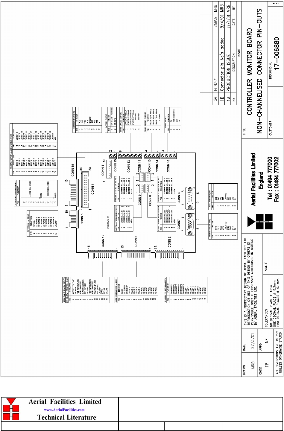
4.9.2 Drg. Nō. 17-006880, Controller/Monitor PCB Pin-Outs
VHF Headstation & In-Line Amplifiers
User Handbook
Handbook Nō.-50-127201FCC Issue No:-A
Date:-14/06/2005 Page:-34 of 45
4.10 24V Single Relay Board (80-008902)
4.10.1 Description
The General Purpose Relay Board allows the inversion of signals and the isolation of
circuits. It is equipped with a single dual pole change-over relay RL1, with completely
isolated wiring, accessed via a 15 way in-line connector.
The relay is provided with polarity protection diodes and diodes for suppressing the
transients caused by "flywheel effect" which can destroy switching transistors or induce
spikes on neighbouring circuits. It’s common use is to amalgamate all the alarm signals
into one, volts-free relay contact pair for the main alarm system.
Note that the board is available for different voltages (12 or 24V) depending on the type
of relay fitted at RL1.
4.11 24V, 400W Power Supply Pack (96-300054)
4.11.1 Description
The power supply unit is a switched-mode type capable of supplying 24V DC at 17.0Amps
continuously. Equipment of this type typically requires approximately 10.0 Amps at 24V
DC, so the PSU will be used conservatively ensuring a long operational lifetime.
No routine maintenance of the PSU is required. If a fault is suspected, then the output voltage
from the power supply may be measured on its output terminals. This is typically set to
24.5V using the multi-turn potentiometer mounted close to the DC output studs on the PSU
PCB.
All the PSU’s used in AFL Cell Enhancers are capable of operation from either 110 or 220V
nominal AC supplies. The line voltage is sensed automatically, so no adjustment or link
setting is needed by the operator.
4.11.2 Technical Specification
AC Input Supply
110 or 220V nominal
Voltages: 90 to 132 or 180 to 264V (absolute limits)
Frequency: 47 to 63Hz
DC Output Supply:
24V DC (nominal)
Voltage: 20 to 28V (absolute limits)
Maximum current: 17A

VHF Headstation & In-Line Amplifiers
User Handbook
Handbook Nō.-50-127201FCC Issue No:-A
Date:-14/06/2005 Page:-35 of 45
4.12 STPS12045TV 60A Dual Diode Assembly
4.12.1 Description
The purpose of these dual diode assemblies is to allow two (or more) DC voltage sources to
be combined, so that the main 24 volt DC rail within the equipment is sourced from either
the mains driven flat-pack, or externally through an XLR connector on the rear panel. The
heavy-duty diodes prevent any reverse current from flowing back to their source or the
alternative supply rail. Combining diodes such as these will also be used if the equipment is
to be powered from external back-up batteries.
4.13 MT2834ZDXK 56kBPS Modem (96-800003)
4.13.1 Description
The modem used is a standard, 56kBPS, O.E.M, ‘Hayes instruction set’ unit. Used in
conjunction with the Controller/Monitor board it is the output termination of all the alarm
system data which is then transmitted into the regular telephone network by dial up from the
BTS. More information on the set-up & use of the modem can be found in the
Controller/Monitor Handbook (17-006801HBKM).

VHF Headstation & In-Line Amplifiers
User Handbook
Handbook Nō.-50-127201FCC Issue No:-A
Date:-14/06/2005 Page:-36 of 45
5. INSTALLATION & COMMISSIONING
5.1 Initial Installation Record
When this equipment is initially commissioned, please use the equipment set-up record sheet
in Appendix A. This will help both the installation personnel and AFL should these figures
be needed for future reference or diagnosis.
5.2 Antenna Installation & Gain Calculations
1 Most Cell Enhancer require two antennas, one a highly directional Yagi or similar
directed towards the donor cell base station, and one a leaky feeder, omni-directional antenna
or Yagi to cover the area in which the mobiles are to be served.
2 The maximum gain at which the Cell Enhancer can be set is limited by the isolation that
can be achieved between these two antennas. Therefore when the antennas have been
installed, inject a signal (at a known power level) into one of them and measure the signal
level received by the other antenna on a spectrum analyser. The isolation can then be
calculated as the difference between these two figures. The gain in each path of the Cell
Enhancer should be set at least 10 dB below this figure, using attenuators as described below
in paragraph 5.
3 Also measure the received signal from the donor cell at the input to the Cell Enhancer
(base port). The gain of the Cell Enhancer downlink path should be set such the donor site
will not overload the Cell Enhancer amplifiers. It is recommended that the input level should
be less than -50dBm at the input of the Cell Enhancer (Base Port). (This figure is assuming
maximum gain, and may be increased by the value of the attenuator fitted in the downlink
path.)
4 Ensure that the mobile facing antenna has at least 70 dB isolation from the nearest mobile.
(This is usually easily achieved when using a leaky feeder.)
5 The Cell Enhancer gain is set by setting the attenuation in each path (uplink and
downlink) between the first two amplifier stages (see markings within the Cell Enhancer or
layout drawings for the exact attenuator locations). Note that the uplink (mobile to base) and
downlink (base to mobile) path gains are set independently. This allows the paths to have
different gains if required to set the correct output power levels.
6 It is recommended that the gains are set such that the Downlink channel output levels
from the Cell Enhancer are typically +30dBm per channel
(Input level + Gain = Output level).
VHF Headstation & In-Line Amplifiers
User Handbook
Handbook Nō.-50-127201FCC Issue No:-A
Date:-14/06/2005 Page:-37 of 45
5.3 Antenna Isolation
Base Site
Mobiles
Ya
g
i or leak
y
feede
r
Ya
g
i
Measure Isolation
Between antennas
B) Install the Cell Enhancer with its gain set 10dB below the isolation
figure obtained above.
Ya
g
i or leak
y
feede
r
Ya
g
i
Base Port Mobile Port
Cell Enhance
r
Base Site
(
donor
)
Mobile
A
)
. First set u
p
the two antennas & measure the isolation between them.

VHF Headstation & In-Line Amplifiers
User Handbook
Handbook Nō.-50-127201FCC Issue No:-A
Date:-14/06/2005 Page:-38 of 45
5.4 General Remarks
The size and weight of the wall-mount case is such that 2/3 persons may be needed to lift the
equipment into position. Test the mechanical installation in the interests of safety, before any
electrical, RF, or optical connections are made.
The equipment must be located on a smooth, flat, perpendicular surface, sheltered if possible,
that is made from a material suitable for bearing the weight of the enclosure, (brick or
concrete is recommended). If the installer is in any doubt about the suitability of a site it is
advised that he/she consult with an appropriately qualified Structural Engineer.
It is also important in determining the location of the case that space is allowed for access to
the front, sides and beneath the equipment to enable maintenance work to be carried out. The
door must be able to fully open but not to obstruct other equipment when doing so.
The location should ideally be served with steel conduits to carry all the cables to and from
the case.
5.5 Electrical Connections
The mains power supply is connected to the IP65 connector located on the bottom/side
surface of the case. It is recommended that the connection is made by a qualified electrician,
who must satisfy himself that the supply will be the correct voltage and of sufficient
capacity.
All electrical and RF connections should be completed and checked prior to power being
applied for the first time.
5.6 RF Connections
Care must be taken to ensure that the correct connections are made with particular attention
made to the base station Tx/Rx ports. In the event that the base transmitter is connected to the
Rx output, damage to the equipment will be done if the base station transmitter is then keyed.
Ensure that connections are kept clean and are fully tightened.

VHF Headstation & In-Line Amplifiers
User Handbook
Handbook Nō.-50-127201FCC Issue No:-A
Date:-14/06/2005 Page:-39 of 45
5.7 RS232 Setup
The RS232 controller/monitor should not need setting up as the specified configuration
with suitable firmware for the application will have been fully tested with the whole of the
system before it leaves the factory. The RS232 PCB’s functions are transparent to the
system if the RS232 board is powered but not utilised.
Further information on the controller board’s setup and remote capabilities is available in
the RS232 Controller/Monitor Handbook, AFL Nō. 17-005801HBKM.

VHF Headstation & In-Line Amplifiers
User Handbook
Handbook Nō.-50-127201FCC Issue No:-A
Date:-14/06/2005 Page:-40 of 45
6. MAINTENANCE
6.1 General Procedures
6.1.1 Quick Fault Checklist
All AFL equipment is individually tested to specification prior to despatch. Failure of this
type of equipment is not common. Experience has shown that a large number of fault
conditions relating to new equipment have simple causes often occurring as a result of
transportation, unpacking and installation. Below are listed some common problems which
have resulted in poor performance or an indicated non-functioning of the equipment.
• Mains power not connected or not switched on.
• External connectors not fitted or incorrectly fitted.
• Internal connectors/ports becoming loose due to transport vibration.
• Wiring becoming detached as a result of heavy handling.
• Input signals not present due to faults in the aerial and feeder system.
• Base transmissions not present due to faults at the base station.
• Modems fitted with incorrect software configuration/and or PIN Nō’s.
• Changes to channel frequencies and inhibiting channels.
• Hand held radio equipment not correctly set to repeater channels.
• Hand held radio equipment not correctly set to base station.
6.1.2 Fault Finding
In the event that the performance of the system is suspect, a methodical and logical approach
to the problem will reveal the cause of the difficulty. The System consists of modules within
a wall mounted, environmentally protected enclosure
Transmissions from the main base stations are passed though the system to the mobile radio
equipment; this could be a handheld radio or a transceiver in a vehicle. This path is referred
to as the downlink. The return signal path from the mobile radio equipment to the base
station is referred to as the uplink.
The first operation is to check the alarms of each of the active units and determine that the
power supplies to the equipment are connected and active. This can be achieved remotely
(via CEMS, the RS232 Coverage Enhancement Management System, if fitted), or locally
with the front door LED’s. The green LED should be illuminated, while the red alarm
indicator should be off. If the alarm LED is on, then the amplifier (or any other alarmed
device connected to the summary output) that is causing the fault will have to be isolated and
individually tested against the original test specification. The individual amplifier modules
have a green LED showing through a hole in their lid/cover, which is illuminated if the unit
is working correctly, and extinguished if not.
If an amplifier is suspect, check the DC power supply to the unit. If no other fault is apparent
use a spectrum analyser to measure the incoming signal level at the input and then after
reconnecting the amplifier input, measure the output level. Consult with the system diagram
to determine the expected gain and compare result.
In the event that there are no alarms on and all units appear to be functioning it will be
necessary to test the system in a systematic manner to confirm correct operation.

VHF Headstation & In-Line Amplifiers
User Handbook
Handbook Nō.-50-127201FCC Issue No:-A
Date:-14/06/2005 Page:-41 of 45
6.1.3 Downlink
Confirm that there is a signal at the expected frequency and strength from the base station. If
this is not present then the fault may lay outside the system. To confirm this, inject a
downlink frequency signal from a known source at the master site BTS input and check for
output at the remote site feeder output.
If a signal is not received at the output it will be necessary to follow the downlink path
through the system to find a point at which the signal is lost. The expected downlink output
for the given input can be found in the end-to-end test specification.
6.1.4 Uplink
Testing the uplink involves a similar procedure to the downlink except that the frequencies
used are those transmitted by the mobile equipment.
6.1.5 Fault repair
Once a faulty component has been identified, a decision must be made on the appropriate
course to carry out a repair. A competent engineer can quickly remedy typical faults such as
faulty connections or cables. The exceptions to this are cable assemblies connecting
bandpass filter assemblies that are manufactured to critical lengths to maintain a 50-ohm
system. Care should be taken when replacing cables or connectors to ensure that items are of
the correct specification. The repair of component modules such as amplifiers and bandpass
filters will not usually be possible in the field, as they frequently require specialist
knowledge and test equipment to ensure correct operation. It is recommended that items of
this type are replaced with a spare unit and the faulty unit returned to AFL for repair.

VHF Headstation & In-Line Amplifiers
User Handbook
Handbook Nō.-50-127201FCC Issue No:-A
Date:-14/06/2005 Page:-42 of 45
6.1.6 Checking service
Following the repair of any part of the system it is recommended that a full end-to-end test is
carried out in accordance with the test specification and that the coverage is checked by
survey.
It is important to bear in mind that the system includes a radiating cable network and base
stations that may be faulty or may have been damaged.
6.1.7 Service Support
Advice and assistance with maintaining and servicing this system are available by contacting
Aerial Facilities Ltd.
6.2 Tools & Test Equipment
The minimum tools and test equipment needed to successfully service this AFL product are
as follows:-
Spectrum analyser: 100kHz to 2GHz (Dynamic range = 90dB).
Signal Generator: 30MHz to 2GHz (-120dBm to 0dBm o/p level).
Attenuator: 20dB, 10W, DC-2GHz, (N male – N female).
Test Antenna: Yagi or dipole for operating frequency.
Digital multi-meter: Universal Volt-Ohm-Amp meter.
Test cable x 2: N male – N male, 2M long RG214.
Test cable x 2: SMA male – N male, 1m long RG223.
Hand tools: Philips #1&2 tip screwdriver.
3mm flat bladed screwdriver.
SMA spanner and torque setter.

VHF Headstation & In-Line Amplifiers
User Handbook
Handbook Nō.-50-127201FCC Issue No:-A
Date:-14/06/2005 Page:-43 of 45
6.3 Care of Modules
6.3.1 General Comments
Many of the active modules contain semiconductor devices utilising MOS technology, which
can be damaged by electrostatic discharge. Correct handling of such modules is mandatory to
ensure their long-term reliability.
To prevent damage to a module, it must be withdrawn/inserted with care. The module may
have connectors on its underside, which might not be visible to the service operative.
6.3.2 Module Removal (LNA’s, general procedure):
The following general instructions should be followed to remove a module:
1 Remove power to the unit
2 Remove all visible connectors (RF, DC & alarm)
3 Release module retaining screws.
4 Slowly but firmly, pull the module straight out of its position. Take care not to twist/turn
the module during withdrawal. (When the module is loose, care may be needed, as there
may be concealed connections underneath).
6.3.3 Module Replacement (general):
1 Carefully align the module into its location then slowly push the module directly straight
into its position, taking care not to twist/turn it during insertion.
2 Reconnect all connectors, RF, alarm, power etc.,(concealed connectors may have to be
connected first).
3 Replace retaining screws (if any).
4 Double-check all connections before applying power.
6.3.4 Power Amplifiers
1) Remove power to the unit. (Switch off @ mains/battery, or remove DC/alarm ‘D’ type
connector)
2) Remove alarm wires from alarm screw terminal block or disconnect multi-way alarm
connector.
3) Carefully disconnect the RF input and output coaxial connectors (usually SMA)
If alarm board removal is not required, go to step 5.
4) There is (usually) a plate attached to the alarm board which fixes it to the amplifier,
remove its retaining screws and the alarm board can be withdrawn from the amplifier in
its entirety. On certain types of amplifier the alarm board is not mounted on a dedicated
mounting plate; in this case it will have to firstly be removed by unscrewing it from the
mounting pillars, in most cases, the pillars will not have not have to be removed before
lifting the amplifier.
VHF Headstation & In-Line Amplifiers
User Handbook
Handbook Nō.-50-127201FCC Issue No:-A
Date:-14/06/2005 Page:-44 of 45
5) If the amplifier to be removed has a heatsink attached, there may be several different ways
it can have been assembled. The most commonly used method, is screws through the fins
of the heatsink to threaded screw holes (or nuts and bolts), into the amplifier within the
main case (side & top mounting). If the heatsink is mounted on the rear of the main case
(this is very unusual), then the fixing method for the heatsink will be from within the case,
otherwise the enclosure would have to be removed from the wall in order to remove the
heatsink).
When the heatsink has been removed, the amplifier may be unscrewed from the main
casing by its four corner fixings and gently withdrawn.
Fitting a new power amplifier module will be the exact reverse of the above.
Note: Do not forget to apply fresh heatsink compound to the heatsink/main case
joint and also between the amplifier and the main case.
6.3.5 Low Power Amplifier Replacement
1 Isolate the mains power supply and disconnect the DC supply connector for the LPA.
2 Disconnect the RF input and output cables from the LPA.
3 Disconnect the alarm connector.
4 Remove the alarm monitoring wires from (D type connector) pins 9 and 10.
5 Remove the LPA module by removing the four retaining screws, replace with a new LPA
module and secure it with the screws.
6 Connect the RF cables to the LPA input and output connectors. Reconnect the wires to
the alarm board connector pins 9 and 10.
7 Reconnect the DC supply connector and turn the mains switch on.
Note: Tighten SMA connectors using only a dedicated SMA torque spanner. If SMA
connectors are over-tightened, irreparable damage will occur. . Do not use adjustable
pliers to loosen/tighten SMA connectors.
Also take care not to drop or knock the module as this can damage (or misalign in the
case of tuned passive modules) sensitive internal components. Always store the modules
in an environmentally friendly location
6.3.6 Module Transportation:
To maintain the operation, performance and reliability of any module it must be stored and
transported correctly. Any module not installed in a whole system must be kept in an anti-
static bag or container. These bags or containers are normally identified by being pink or
black, and are often marked with an ESD label. Any module sent back to AFL for
investigation/repair must be so protected. Please contact AFL’s quality department before
returning a module.
VHF Headstation & In-Line Amplifiers
User Handbook
Handbook Nō.-50-127201FCC Issue No:-A
Date:-14/06/2005 Page:-45 of 45
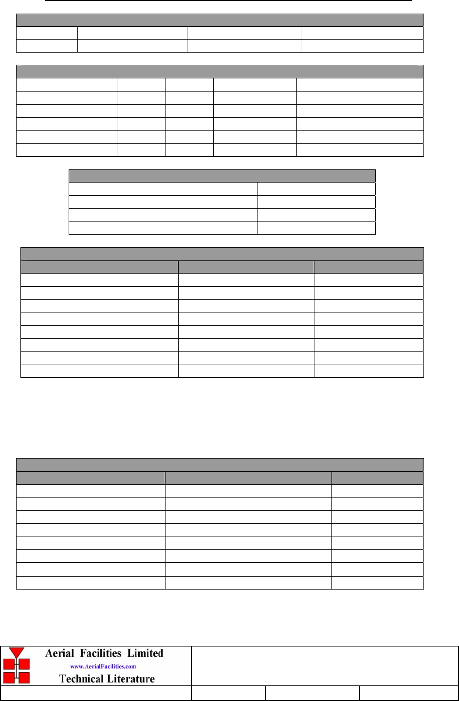
APPENDIX A INITIAL EQUIPMENT SET-UP CALCULATIONS
GENERAL INFORMATION
Site Name: Client Name:
Date: AFL Equip. Model Nō.
ANTENNA SYSTEMS
Model Gain Azimuth Comments
A - Service Antenna
B – Donor Antenna
Type Loss Length Comments
C – Service Feeder
D – Donor Feeder
INITIAL PARAMETERS
E – CE Output Power dBm
F – Antenna Isolation dB
G – Input signal level from donor BTS dBm
Operating Voltage V
DOWNLINK CALCULATIONS
Parameter Comments Value
Input signal level (G) dBm
CE max. o/p power (E) dBm
Gain setting E - G dB
Isolation required (Gain + 10dB) dB
Service antenna gain (A) dB
Service antenna feeder loss (C) dB
Effective radiated power (ERP) E+A-C dBm
Attenuator setting CE gain-gain setting dB
If the input signal level in the uplink path is known and steady, use the following calculation
table to determine the gain setting. If the CE features Automatic Gain Control the attenuator
should be set to zero and if not, then the attenuation setting for both uplink and downlink
should be similar.
UPLINK CALCULATIONS
Parameter Comments Value
Input signal level dBm
CE max. o/p power (E) dBm
Gain setting dB
Required isolation dB
Donor antenna gain (B) dB
Donor antenna feeder loss (D) dB
Effective radiated power (ERP) E+B-D dBm
Attenuator setting (CE gain-gain setting) dB