PBE Europe as Axell Wireless 50-1467SERIES 50-1467 Series VHF Chanellised air interface User Manual 50 146501 50 146601 50 146701HBKM
Axell Wireless 50-1467 Series VHF Chanellised air interface 50 146501 50 146601 50 146701HBKM
UserManual.wiki
>
PBE Europe as Axell Wireless
>
50 1467SERIES User Manual
Manual
Navigation menu
Upload a User Manual
Namespaces
Wiki Guide
HTML
PDF
Info
Views
User Manual
Discussion / Help
Navigation

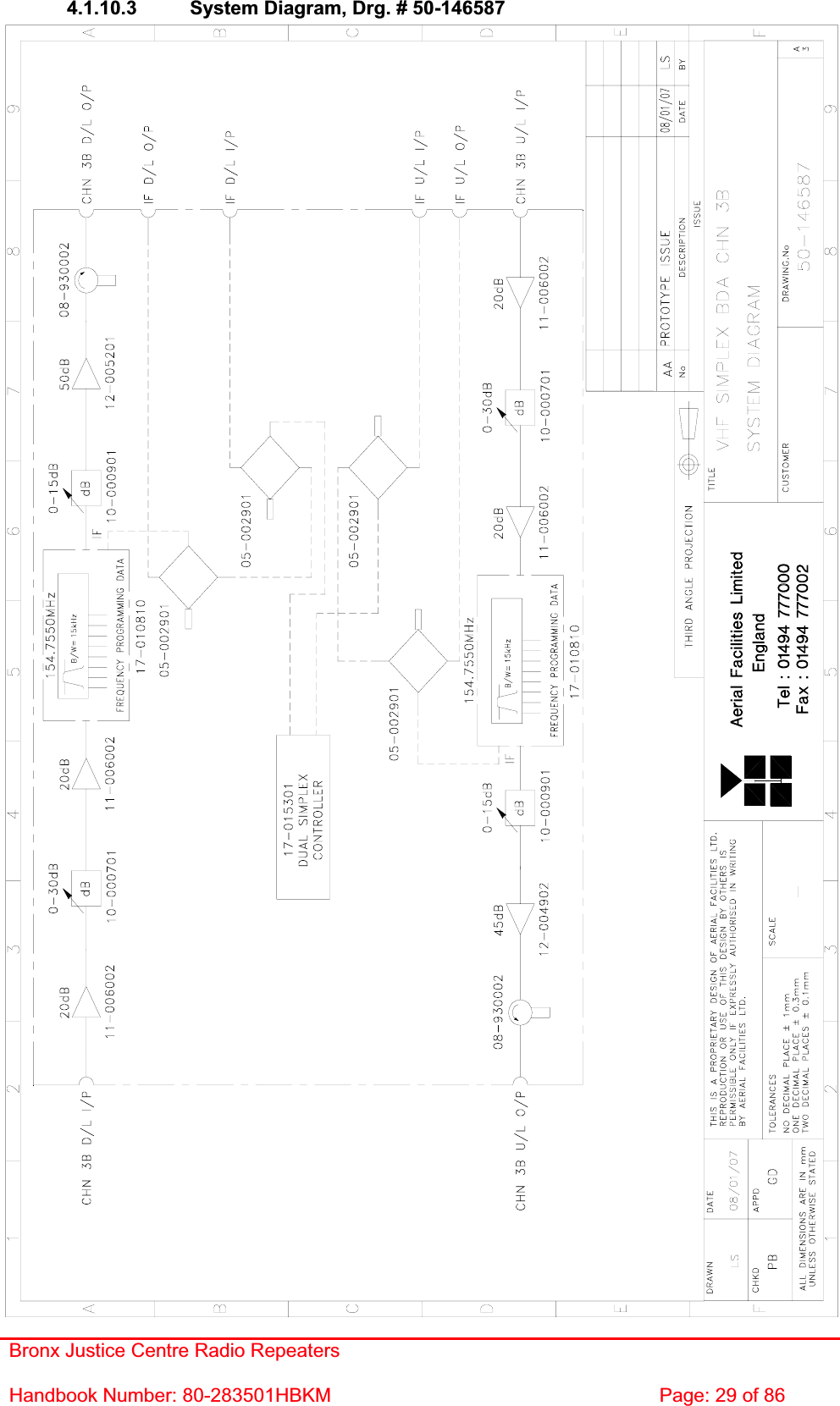
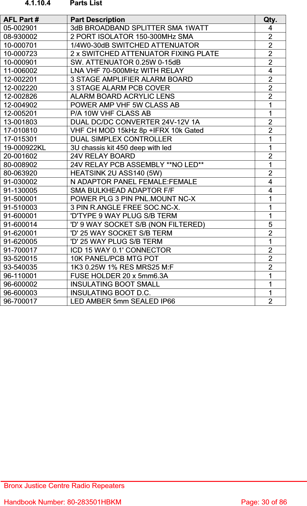
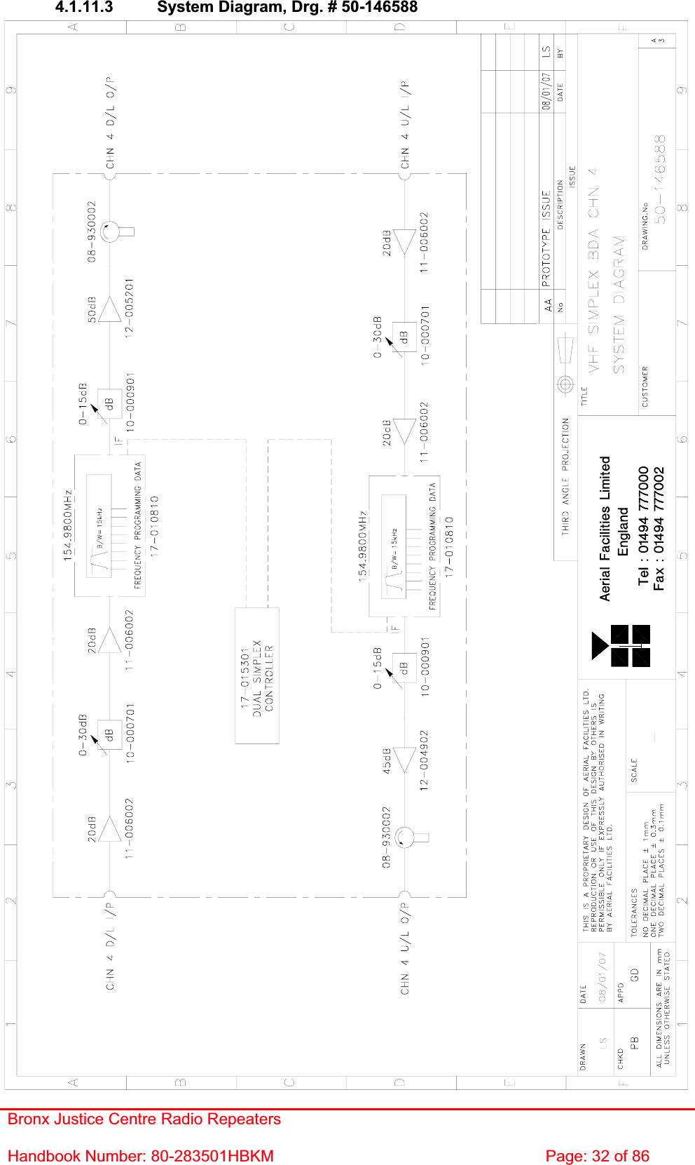
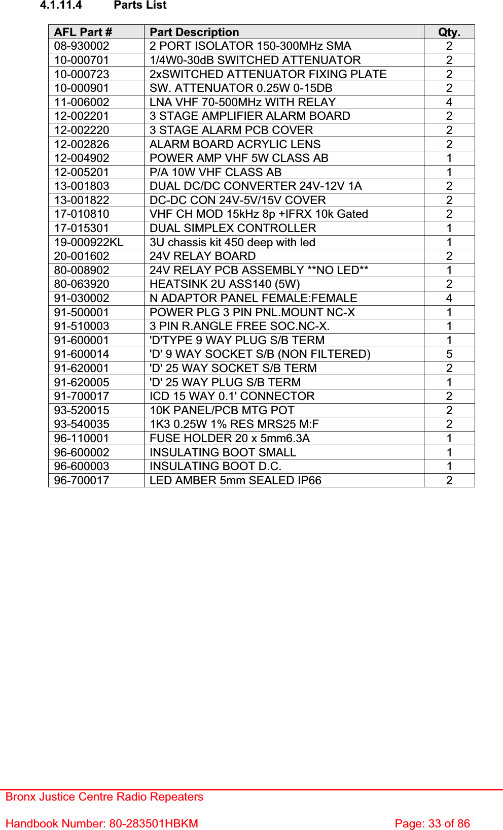
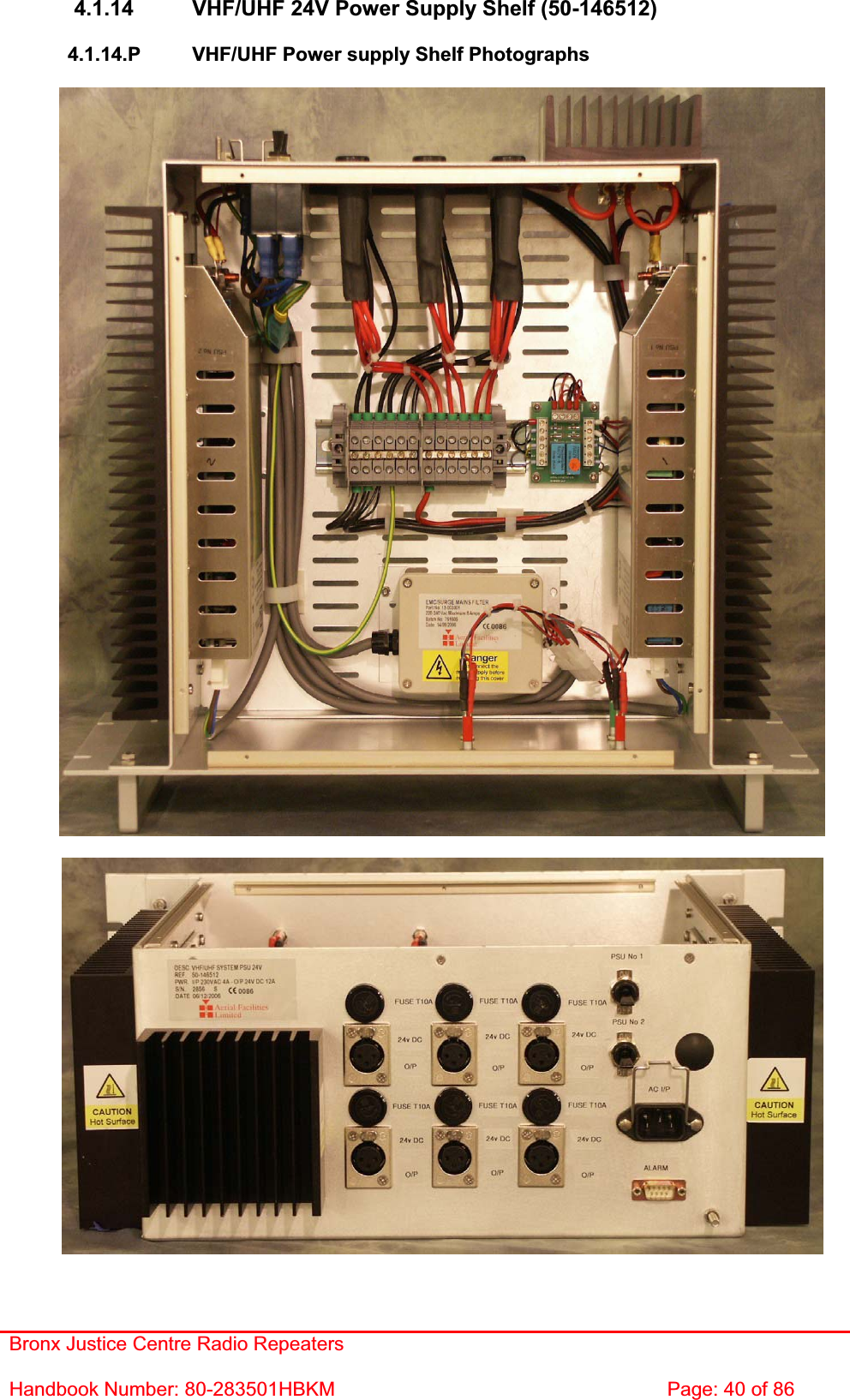
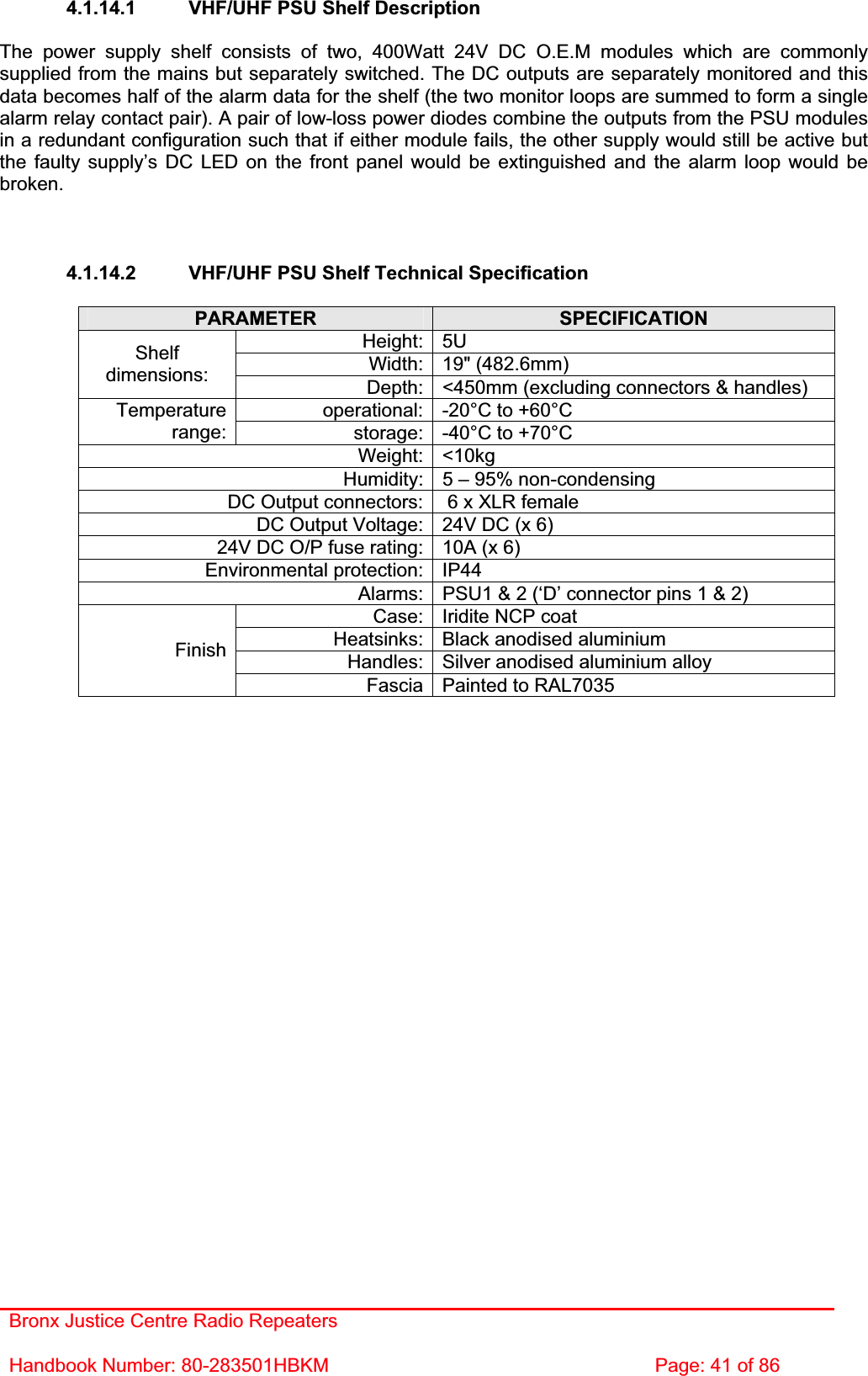
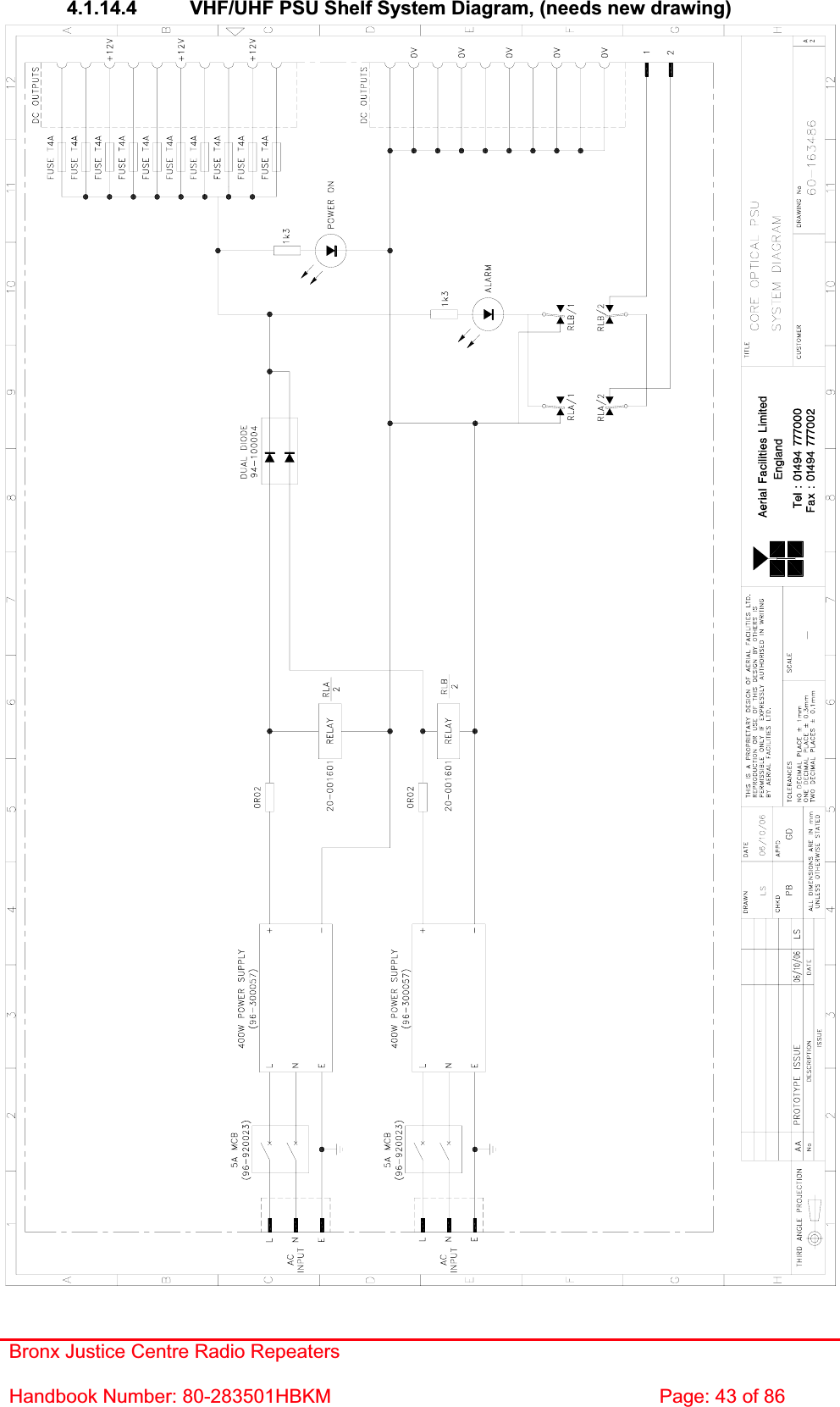
![Bronx Justice Centre Radio Repeaters Handbook Number: 80-283501HBKM Page: 42 of 86 4.1.14.3 VHF/UHF PSU Shelf Parts List AFL Part # Part Description Qty.13-003301 MAINS FILTER 8AMP ASSEMBLY 1 16-000222 DUPLEXER/CELL ENHANCER CASE RAIL 4 20-001601 12V RELAY BOARD 1 80-008920 DUAL PSU HEATSINK 2 80-008921 DUAL PSU CASE 1 80-008922 DUAL PSU LID 1 80-008925 DUAL PSU FRONT PANEL 1 91-500025 3 PIN RIGHT ANGLE FREE PLUG NC-X 6 91-510004 3 PIN PNL.MOUNT SOCKET NC-X 6 91-510035 3 WAY MATE N LOK PLUG HOUSING 2 91-520001 PWR MAINS INL FIXED/SOLD.TERMS 1 91-520005 MAINS LEAD 1 91-520010 MAINS RETAINING CLIP 1 91-520032 MATE N LOK SOCKET CONTACT 20/14 AWG 6 91-600015 'D' 9 WAY PLUG S/B (NON FILTERED) 1 91-800014 3 WAY TERMINAL BLOCK 1 91-800015 TRIPLE DECK TERMINAL BLOCK 8 91-800016 TRIPLE DECK TERMINAL JUMPER 6 91-800017 TRIPLE DECK TERMINAL END 1 91-800028 DIN RAIL END-STOP 2 91-800031 SYMETRIC 35 x 7.5mm DIN RAIL 0 92-900014 DIN RAIL (TOP HAT) EARTH CLAMP M5 1 93-510077 0R02 50W RESISTOR ALUMINIUM CLAD 2 94-100004 STPS12045TV 60A DUAL DIODE 1 95-100007 TX.FERRITE ISOL.HT.SINK B/ANOD 3 96-110034 FUSE HOLDER 16-30A, 32mm BODY ONLY 6 96-110064 FUSE HOLDER 16-30A, 32mm INSERT 6 96-300054 24V 17A PSU 400W (XP BCC) 2 96-600001 INSULATING BOOT LARGE 1 96-700034 LED RED 5mm IP67 INTEGRAL RES. 24V 1 96-700035 LED GREEN 5mm IP67 INTEGRAL RES 24V 2 96-920023 5A CIRCUIT BREAKER (ETA) 2 97-400002 HANDLE TYPE H6803 4U.[ALLOY] 2](https://usermanual.wiki/PBE-Europe-as-Axell-Wireless/50-1467SERIES/User-Guide-755637-Page-42.png)