PBE Europe as Axell Wireless 50-1892SERIES 50-189201 5 Channel VHF Repeater User Manual
Axell Wireless 50-189201 5 Channel VHF Repeater
Manual

5 Ch. VHF Radio Repeater Equipment
Document Number 50-189201HBK – Issue 1 Page 1 of 48
5 Ch. VHF Radio Repeater Equipment
(Bi-directional Amplifier)
For
Day Wireless Systems
AFL Works Order Q116073
AFL Product Part No. 50-189201 (5 Ch. VHF System 80dB)

5 Ch. VHF Radio Repeater Equipment
Document Number 50-189201HBK – Issue 1 Page 2 of 48
Table of Contents
1. INTRODUCTION.......................................................................................................................... 4
1.1. Scope and Purpose of Document ............................................................................................. 4
1.2. Limitation of Liability Notice ...................................................................................................... 4
2. SAFETY CONSIDERATIONS ...................................................................................................... 5
2.1. Earthing of Equipment .............................................................................................................. 5
2.2. Electric Shock Hazard............................................................................................................... 5
2.3. RF Radiation Hazard ................................................................................................................ 5
2.4. Lifting and other Health and Safety Recommendations............................................................ 5
2.5. Chemical Hazard ...................................................................................................................... 6
2.6. Laser Safety.............................................................................................................................. 6
2.7. Emergency Contact Numbers...................................................................................................6
3. EQUIPMENT OVERVIEW............................................................................................................ 7
3.1. Overall System Diagram ........................................................................................................... 8
4. BDA VHF SYSTEM RACK 1 (50-189212) ................................................................................... 9
4.1. BDA VHF System Rack 1 (50-189212) System diagram........................................................ 10
4.2. BDA VHF System Rack 1 (50-189212) Photographs ............................................................. 11
4.3. BDA VHF Downlink Output Combiner (50-189208)................................................................ 13
4.3.1. BDA VHF Downlink Output Combiner (50-189208) Major Components .......................... 13
4.3.2. BDA VHF Downlink Output Combiner (50-189208) System diagram .............................. 14
4.4. BDA VHF Uplink Input Splitter (50-189210)............................................................................ 15
4.4.1. BDA VHF Uplink Input Splitter (50-189210) Major Components...................................... 15
4.4.2. BDA VHF Uplink Input Splitter (50-189210) System diagram .......................................... 16
4.5. BDA VHF Channel Shelves (50-189202 to 50-189206) ......................................................... 17
4.5.1. BDA VHF Channel Shelves Major Components .............................................................. 17
4.5.2. BDA VHF Channel 1 Shelf (50-189202) System diagram................................................ 20
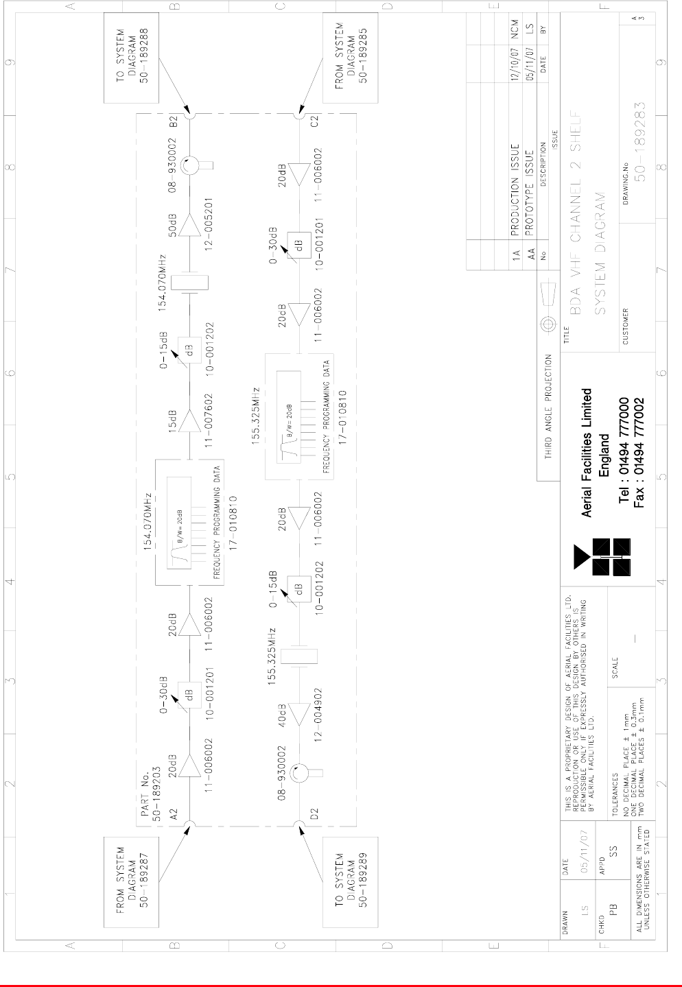
4.5.3. BDA VHF Channel 2 Shelf (50-189203) System diagram................................................ 21
4.5.4. BDA VHF Channel 3 Shelf (50-189204) System diagram................................................ 22
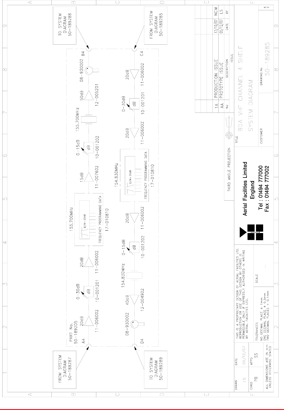
4.5.5. BDA VHF Channel 4 Shelf (50-189205) System diagram................................................ 23
4.5.6. BDA VHF Channel 5 Shelf (50-189206) System diagram................................................ 24
4.6. BDA VHF UPLINK OUTPUT COMBINER (50-189209)......................................................... 25
4.6.1. BDA VHF Uplink Output Combiner (50-189209) Major Components............................... 25
4.6.2. BDA VHF Uplink Output Combiner (50-189209) System Diagram .................................. 26
4.7. BDA VHF DOWNLINK INPUT SPLITTER (50-189207).......................................................... 27
4.7.1. BDA VHF Downlink Input Splitter (50-189207) Major Components ................................. 27
4.7.2. BDA VHF Downlink Input Splitter (50-189207) System Diagram..................................... 28
4.8. 24V PSU Shelf (50-146512) ...................................................................................................29
4.8.1. 24V PSU Shelf (50-146512) Specification ....................................................................... 29
4.8.2. 24V PSU Shelf (50-146512) Major Components ............................................................. 29
4.8.2. 24V PSU Shelf (50-146512) System Diagram ................................................................. 31
5. BDA VHF SYSTEM RACK 2 (50-189213) ................................................................................. 32
5.1. BDA VHF System Rack 2 (50-189213) System Diagram ....................................................... 34
5.2. Hybrid Splitter/Combiner Tray (50-189211) ............................................................................ 35
5.2.1. Hybrid Splitter/Combiner Tray (50-189211) Major Components ...................................... 35
5.2.2. Hybrid Splitter/Combiner Tray (50-189211) System Diagram.......................................... 36
6. BDA VHF SYSTEM RACK 3 (50-189214) ................................................................................. 37
6.1. BDA VHF System Rack 3 (50-189214) System Diagram ....................................................... 39
7. INSTALLATION.......................................................................................................................... 40
7.1 Initial Installation Record......................................................................................................... 40
8. FAULT FINDING & MAINTENANCE.......................................................................................... 40
8.1 General Fault Finding Procedures.......................................................................................... 40
8.2 Downlink ................................................................................................................................. 40
8.3 Uplink...................................................................................................................................... 41
8.4 Fault repair.............................................................................................................................. 41
8.5 Checking service..................................................................................................................... 41
8.6 Service Support ...................................................................................................................... 41
8.7 Tools & Test Equipment.......................................................................................................... 41

5 Ch. VHF Radio Repeater Equipment
Document Number 50-189201HBK – Issue 1 Page 3 of 48
8.8 General Maintenance Procedures ..........................................................................................42
8.9 Module Removal (LNAs, general procedure).......................................................................... 42
8.10 Module Replacement (general) ........................................................................................... 42
8.11 Power Amplifiers.................................................................................................................. 42
8.12 Low Power Amplifier Replacement...................................................................................... 43
8.13 Module Transportation......................................................................................................... 43
APPENDIX A ....................................................................................................................................... 44
A.1. Glossary of Terms used in this document ........................................................................... 44
A.2. Key to Drawing Symbols used in this document..................................................................45
A.3. EC Declaration of Conformity .............................................................................................. 46
A.4. Amendment List Record Sheet............................................................................................ 47

5 Ch. VHF Radio Repeater Equipment
Document Number 50-189201HBK – Issue 1 Page 4 of 48
1. INTRODUCTION
1.1. Scope and Purpose of Document
This handbook is for use solely with the equipment identified by the Aerial Facilities Limited (AFL) Part
Number shown on the front cover. It is not to be used with any other equipment unless specifically
authorised by AFL. This is a controlled release document and, as such, becomes a part of Aerial
Facilities’ Total Quality Management System. Alterations and modification may therefore only be
performed by AFL.
AFL recommends that the installer of this equipment familiarise themselves with the safety and
installation procedures contained within this document before installation commences.
The purpose of this handbook is to provide the user/maintainer with sufficient information to service
and repair the equipment to the level agreed. Maintenance and adjustments to any deeper level must
be performed by AFL, normally at the company’s repair facility in Chesham, England.
This handbook has been prepared in accordance with BS 4884, and AFL’s Quality procedures, which
maintain the company’s registration to BS EN ISO 9001:2000 and to the R&TTE Directive of the
European Parliament. Copies of the relevant certificates and the company Quality Manual can be
supplied on application to the Quality Manager.
This document fulfils the relevant requirements of Article 6 of the R&TTE Directive.
1.2. Limitation of Liability Notice
This manual is written for the use of technically competent operators/service persons. No liability is
accepted by AFL for use or misuse of this manual, the information contained therein, or the
consequences of any actions resulting from the use of the said information, including, but not limited
to, descriptive, procedural, typographical, arithmetical, or listing errors.
Furthermore, AFL does not warrant the absolute accuracy of the information contained within this
manual, or its completeness, fitness for purpose, or scope.
AFL has a policy of continuous product development and enhancement, and as such, reserves the
right to amend, alter, update and generally change the contents, appearance and pertinence of this
document without notice.
All AFL products carry a twelve month warranty from date of shipment. The warranty is expressly on a
return to base repair or exchange basis and the warranty cover does not extend to on-site repair or
complete unit exchange.
5 Ch. VHF Radio Repeater Equipment
Document Number 50-189201HBK – Issue 1 Page 5 of 48
2. SAFETY CONSIDERATIONS
2.1. Earthing of Equipment
Equipment supplied from the mains must be connected to grounded outlets and earthed
in conformity with appropriate local, national and international electricity supply and
safety regulations.
2.2. Electric Shock Hazard
The risk of electrical shocks due to faulty mains driven power supplies whilst
potentially ever present in any electrical equipment, would be minimised by adherence
to good installation practice and thorough testing at the following stages:
a) Original assembly.
b) Commissioning.
c) Regular intervals, thereafter.
All test equipment must be in good working order prior to its use. High current power supplies can be
dangerous because of the possibility of substantial arcing. Always switch off during disconnection and
reconnection.
2.3. RF Radiation Hazard
RF radiation, (especially at UHF frequencies) arising from transmitter outputs
connected to AFL’s equipment, must be considered a safety hazard.
This condition might only occur in the event of cable disconnection, or because a
‘spare’ output has been left un-terminated. Either of these conditions would impair the
system’s efficiency. No investigation should be carried out until all RF power sources have been
removed. This would always be a wise precaution, despite the severe mismatch between the
impedance of an N type connector at 50, and that of free space at 377, which would severely
mitigate against the efficient radiation of RF power. Radio frequency burns could also be a hazard, if
any RF power carrying components were to be carelessly touched!
Antenna positions should be chosen to comply with requirements (both local & statutory) regarding
exposure of personnel to RF radiation. When connected to an antenna, the unit is capable of
producing RF field strengths, which may exceed guideline safe values especially if used with
antennas having appreciable gain. In this regard the use of directional antennas with backscreens
and a strict site rule that personnel must remain behind the screen while the RF power is on, is
strongly recommended.
Where the equipment is used near power lines or in association with temporary masts not having
lightning protection, the use of a safety earth connected to the case-earthing bolt is strongly advised.
2.4. Lifting and other Health and Safety Recommendations
Certain items of AFL equipment are heavy and care should be taken when lifting them
by hand. Ensure that a suitable number of personnel, appropriate lifting apparatus
and appropriate personal protective equipment is used especially when installing Cell
Enhancers above ground e.g. on a mast or pole.
5 Ch. VHF Radio Repeater Equipment
Document Number 50-189201HBK – Issue 1 Page 6 of 48
2.5. Chemical Hazard
Beryllium Oxide, also known as Beryllium Monoxide, or Thermalox™, is sometimes
used in devices within equipment produced by Aerial Facilities Ltd. Beryllium oxide
dust can be toxic if inhaled, leading to chronic respiratory problems. It is harmless if
ingested or by contact.
Products that contain beryllium are load terminations (dummy loads) and some power amplifiers.
These products can be identified by a yellow and black “skull and crossbones” danger symbol (shown
above). They are marked as hazardous in line with international regulations, but pose no threat under
normal circumstances. Only if a component containing beryllium oxide has suffered catastrophic
failure, or exploded, will there be any danger of the formation of dust. Any dust that has been created
will be contained within the equipment module as long as the module remains sealed. For this reason,
any module carrying the yellow and black danger sign should not be opened. If the equipment is
suspected of failure, or is at the end of its life-cycle, it must be returned to Aerial Facilities Ltd for
disposal.
To return such equipment, please contact the Quality Department, who will give you a Returned
Materials Authorisation (RMA) number. Please quote this number on the packing documents, and on
all correspondence relating to the shipment.
PolyTetraFluoroEthylene, (P.T.F.E.) and P.T.F.E. Composite Materials
Many modules/components in AFL equipment contain P.T.F.E. as part of the RF insulation barrier.
This material should never be heated to the point where smoke or fumes are evolved. Any person
feeling drowsy after coming into contact with P.T.F.E. especially dust or fumes should seek medical
attention.
2.6. Laser Safety
General good working practices adapted from
EN60825-2: 2004/ EC 60825-2:2004
Do not stare with unprotected eyes or with any unapproved optical device at the fibre
ends or connector faces or point them at other people, Use only approved filtered or attenuating
viewing aids.
Any single or multiple fibre end or ends found not to be terminated (for example, matched, spliced)
shall be individually or collectively covered when not being worked on. They shall not be readily
visible and sharp ends shall not be exposed.
When using test cords, the optical power source shall be the last connected and the first
disconnected; use only approved methods for cleaning and preparing optical fibres and optical
connectors.
Always keep optical connectors covered to avoid physical damage and do not allow any dirt/foreign
material ingress on the optical connector bulkheads.
The optical fibre jumper cable maximum bend radius is 3cm; any smaller radii may result in optical
cable breakage or excessive transmission losses.
Caution: The FO units are NOT weather proof.
2.7. Emergency Contact Numbers
The AFL Quality Department can be contacted on:
Telephone +44 (0)1494 777000
Fax. +44 (0)1494 777002
e-mail qa@aerialfacilities.com

5 Ch. VHF Radio Repeater Equipment
Document Number 50-189201HBK – Issue 1 Page 7 of 48
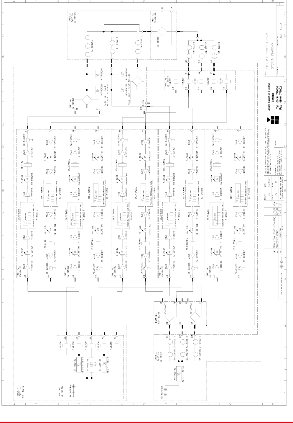
3. EQUIPMENT OVERVIEW
5 channel radio repeater 50-189201 is supplied in three 43U equipment mounting racks.
Rack 1 (50-189212) houses the main amplification modules along with the various splitters and
combiners.
Rack 2 (50-189213) houses the Cavity FIlters for the TX (Downlink) path
Rack 3 (50-189214) houses the Cavity FIlters for the RX (Uplink) path
Downlink.
Channel 1 – 154.190MHz
Channel 2 – 154.070MHz
Channel 3 – 158.910MHz
Channel 4 – 155.700MHz
Channel 5 – 158.850 MHz
The input splitter shelf (50-189207) receives Downlink VHF signals from the off-air RX antenna and
the signal is split and passed through a series of bandpass and crystal filters. The resultant five signal
paths then leave the shelf, each path going to the downlink section of a dedicated amplifier shelf
(BDA VHF Channel Shelves 1 to 5, 50-189202/06); these amplifier shelves also contain channel
selective modules to achieve the narrow bandwidth required.
Upon leaving the Amplifier shelves the five signal paths enter BDA VHF Downlink Output Combiner
(50-189208) where the five separate signal paths are combined into three. The three signal paths are
then fed into the cavity combiner in Rack 2 where they are combined into a single signal path before
being fed into BDA VHF DAS Hybrid Splitter/Combiner (50-189211) where the signal path is split into
two feeds, one for each LCX feed
Uplink
Channel 1 – 156.195MHz
Channel 2 – 155.325MHz
Channel 3 – 154.785MHz
Channel 4 – 154.830MHz
Channel 5 – 156.150 MHz
Uplink signals from the LCX are fed into BDA VHF DAS Hybrid Splitter/Combiner (50-189211) where
they are combined into a single signal path and passed into the first stage of the cavity filter in Rack
3. In the first stage cavity filter the signal path is split into three and each path passes through a cavity
filtering section and the three signal paths then are fed into the BDA VHF Uplink Input Splitter (50-
189210) in Rack 1, here the three paths are split into five and each path pases through a crystal filter
which passes the channel required.
Upon leaving the BDA VHF Uplink Input Splitter, each of the five signal paths is fed into the uplink
section of a dedicated amplifier shelf (BDA VHF Channel Shelves 1 to 5, 50-189202/06); these
amplifier shelves also contain channel selective modules to achieve the narrow bandwidth required.
From the amplifier shelves the five signal paths are fed into the Uplink Output Combiner (50-189209)
where the five signal paths are combined into three path before being fed into the second stage of the
cavity filter in Rack 3. After passing through the cavity filters the separate signal paths are combined
into a single path whis passes through a bandpass filter before being fed to the TX antenna
5 Ch. VHF Radio Repeater Equipment
Document Number 50-189201HBK – Issue 1 Page 8 of 48
3.1. Overall System Diagram
Drawing number 50-189281

5 Ch. VHF Radio Repeater Equipment
Document Number 50-189201HBK – Issue 1 Page 9 of 48
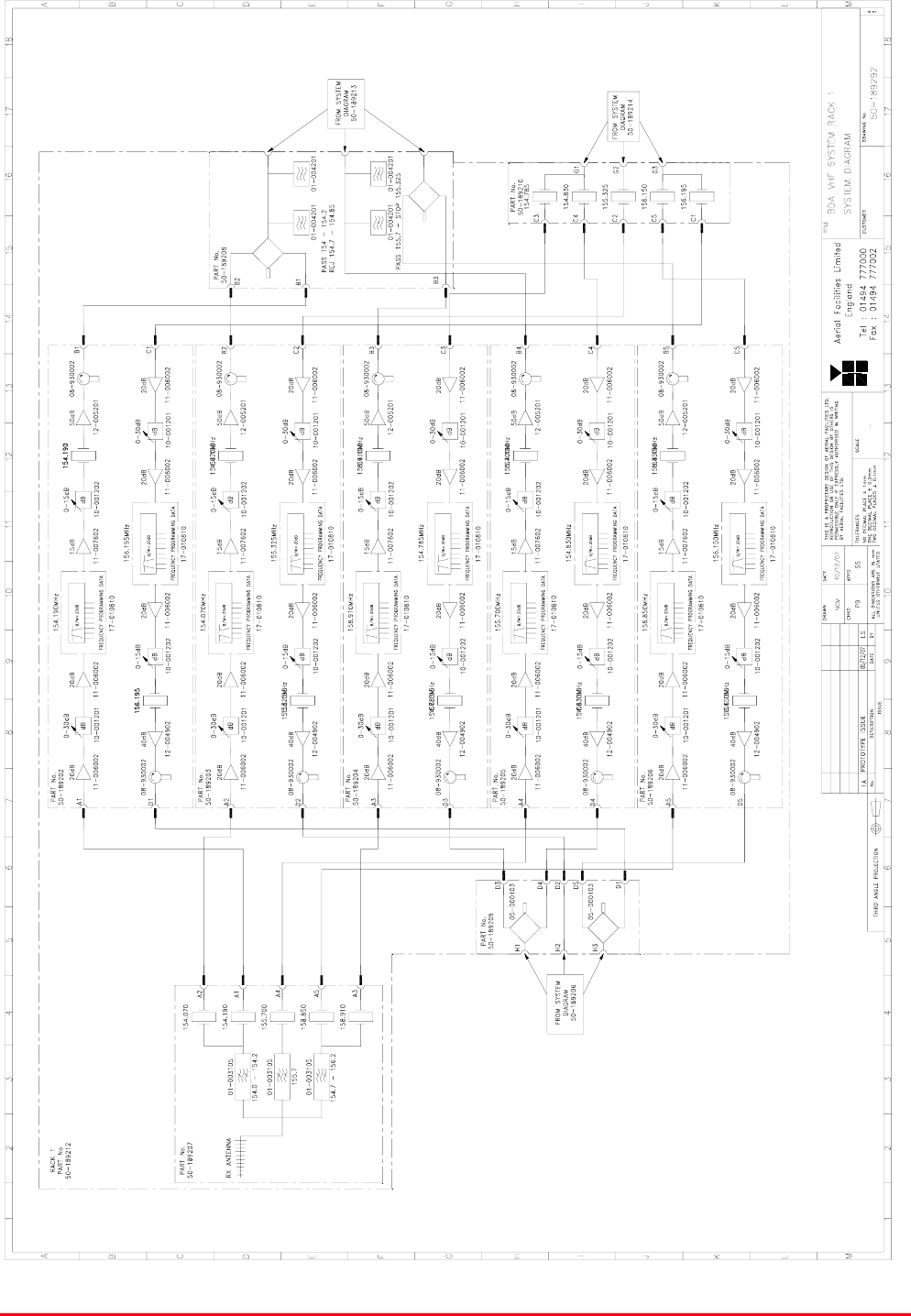
4. BDA VHF SYSTEM RACK 1 (50-189212)
Rack 1 (50-189212) houses the main amplification modules for uplink and downlink along with the
various splitters, combiners and the inputs from the RX antenna and the outputs to the TX antenna
Rack 1 is a 43U equipment mounting rack (600mm x 600mm) and comprised of the following
modules, listed from the top of the rack
Component
Part
Component Part Description Qty Per
Assembly
50-189208 BDA VHF Downlink Output Combiner 1
50-189210 BDA VHF Uplink Input Splitter 1
50-189202 BDA VHF Channel 1 Shelf 1
50-189203 BDA VHF Channel 2 Shelf 1
50-189204 BDA VHF Channel 3 Shelf 1
50-189205 BDA VHF Channel 4 Shelf 1
50-189206 BDA VHF Channel 5 Shelf 1
50-189209 BDA VHF Uplink Output Combiner 1
50-189207 BDA VHF Downlink Input Splitter 1
50-146512 24V PSU Shelf 1
5 Ch. VHF Radio Repeater Equipment
Document Number 50-189201HBK – Issue 1 Page 10 of 48
4.1. BDA VHF System Rack 1 (50-189212) System diagram
Drawing number 50-189292
5 Ch. VHF Radio Repeater Equipment
Document Number 50-189201HBK – Issue 1 Page 11 of 48
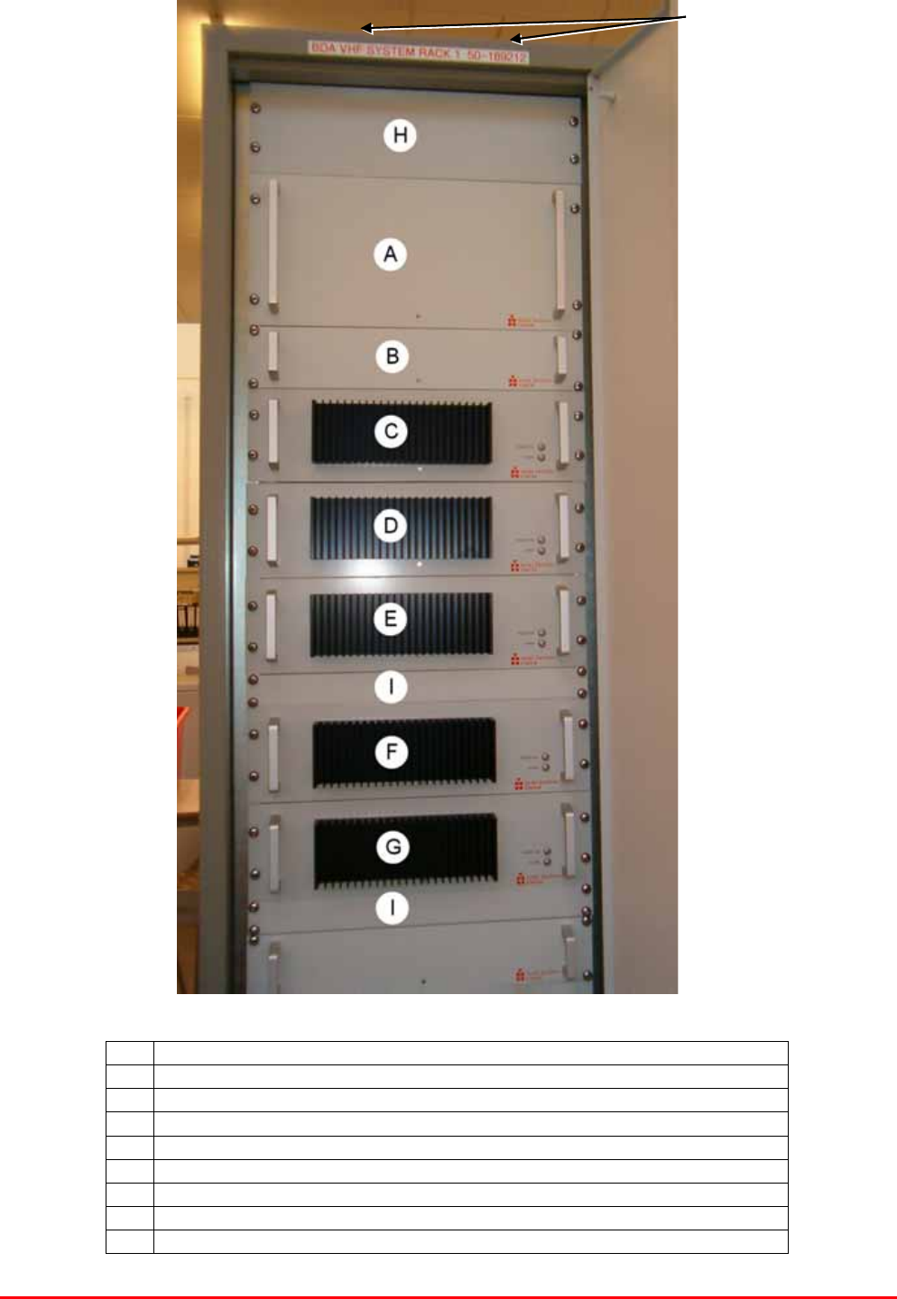
4.2. BDA VHF System Rack 1 (50-189212) Photographs
Top of rack
Rack Interconnections
(see below)
A BDA VHF Downlink Output Combiner 50-189208
B BDA VHF Uplink Input Splitter 50-189210
C BDA VHF Channelised Amplifier Channel 1 Shelf 50-189202
D BDA VHF Channelised Amplifier Channel 2 Shelf 50-189203
E BDA VHF Channelised Amplifier Channel 3 Shelf 50-189204
F BDA VHF Channelised Amplifier Channel 4 Shelf 50-189205
G BDA VHF Channelised Amplifier Channel 5 Shelf 50-189206
H 2U Blanking Panel
I 1U Blanking Panel
5 Ch. VHF Radio Repeater Equipment
Document Number 50-189201HBK – Issue 1 Page 12 of 48
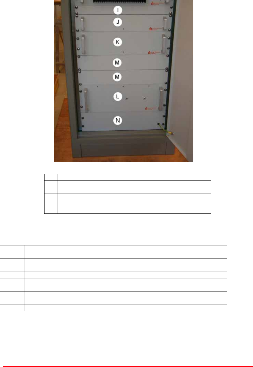
Bottom of rack
I 1U Blanking Panel
J BDA VHF Uplink Output Combiner 50-189209
K BDA VHF Downlink Input Splitter 50-189207
L VHF/UHF System PSU 24v 50-146512
M 2U Blanking Panel
N 3U Blanking Panel
Rack interconnections are on the top of the rack rack
Ant Connection to RX Antenna
E1 D/L Channel 4 to Cavity Combiner Rack 2
E2 Combined D/L Channel 1 & 2 to Cavity Combiner Rack 2
E3 Combined D/L Channel 3 & 5 to Cavity Combiner Rack 2
G1 Combined U/L Channel 3 & 4 from first stage Cavity Combiner Rack 3
G2 U/L Channel 2 from first stage Cavity Combiner Rack 3
G3 Combined U/L Channel 1 & 5 from first stage Cavity Combiner Rack 3
H1 Combined U/L Channel 3 & 4 to second stage Cavity Combiner Rack 3
H2 U/L Channel 2 to second stage Cavity Combiner Rack 3
H3 Combined U/L Channel 1 & 5 to second stage Cavity Combiner Rack 3
5 Ch. VHF Radio Repeater Equipment
Document Number 50-189201HBK – Issue 1 Page 13 of 48
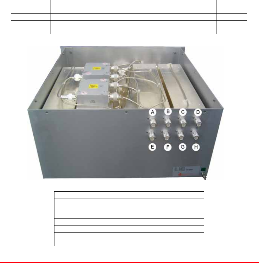
4.3. BDA VHF Downlink Output Combiner (50-189208)
The BDA VHF Downlink Output Combiner takes amplified signals from the Channelised Amplifier
shelves in Rack 1 and combines them before passing the signals to the Cavity Combiner in rack 2
Channels 1 and 2 are combined by hybrid combiner (01-004201) and the resultant signal is passed
through two notch filters (01-004201) before leaving the shelf to go to the cavity combiner in rack 2
Channels 3 and 5 are combined by hybrid combiner (01-004201) and the resultant signal is passed to
the cavity combiner in rack 2
Channel 4 is passed through two notch filters (01-004201) before leaving the shelf to go to the cavity
combiner in rack 2
This is a passive shelf and has no connection to the PSU and no alarms.
4.3.1. BDA VHF Downlink Output Combiner (50-189208) Major
Components
Component
Part
Component Part Description Qty Per
Assembly
01-004201 Notch Filter 4
05-000103 Hybrid combiner 2
97-100010K 5U Rack Mount Chassis
A Port E2 Combined D/L Channel 1 & 2 output
B Port B5 D/L Channel 5 input
C Port B3 D/L Channel 3 input
D Port B1 D/L Channel 1 input
E Port E3 Combined D/L Channel 3 & 5 output
F Port E1 D/L Channel 4 output
G Port B4 D/L Channel 4 input
H Port B2 D/L Channel 2 input
5 Ch. VHF Radio Repeater Equipment
Document Number 50-189201HBK – Issue 1 Page 14 of 48
4.3.2. BDA VHF Downlink Output Combiner (50-189208) System diagram
Drawing number 50-189288
5 Ch. VHF Radio Repeater Equipment
Document Number 50-189201HBK – Issue 1 Page 15 of 48
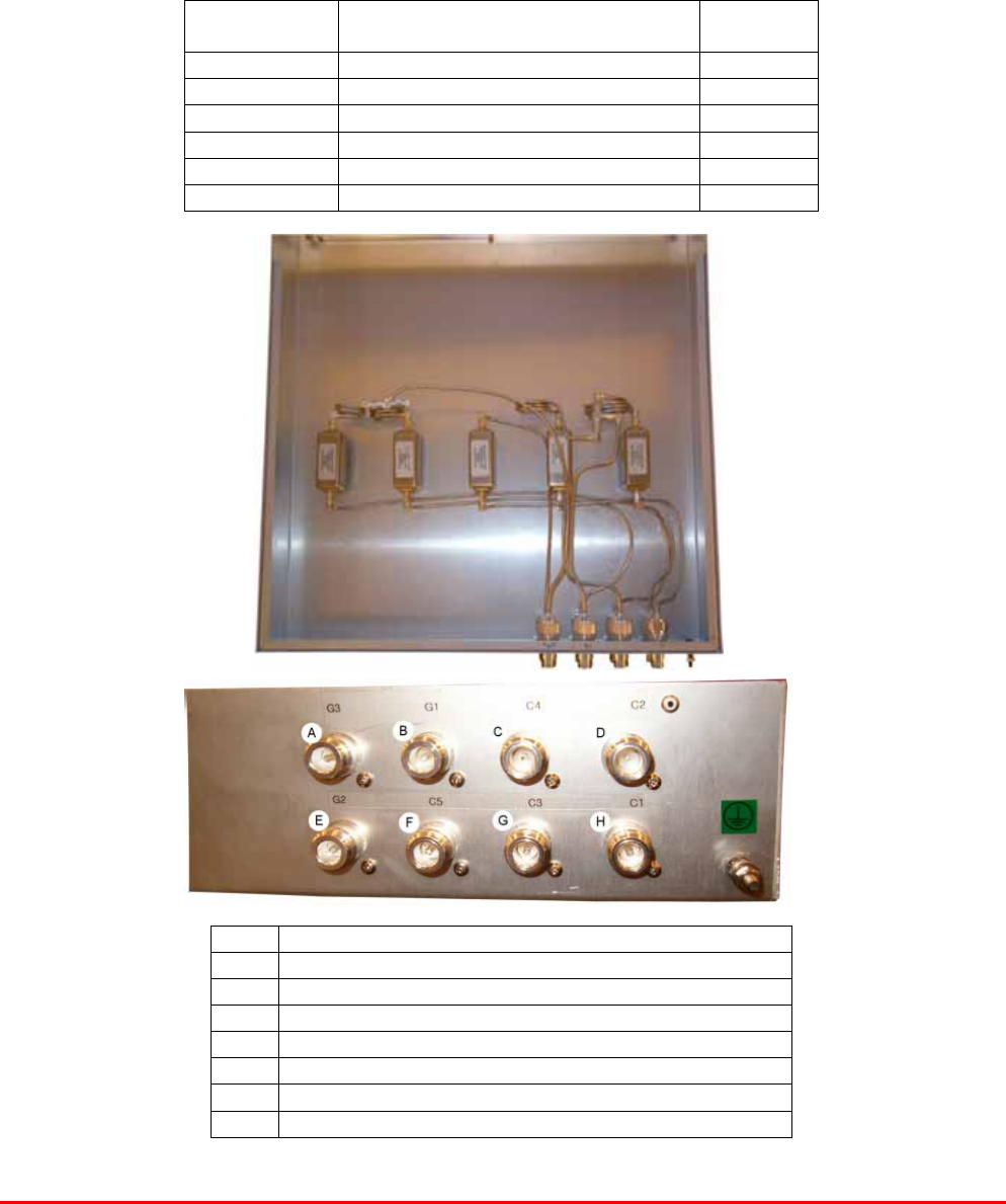
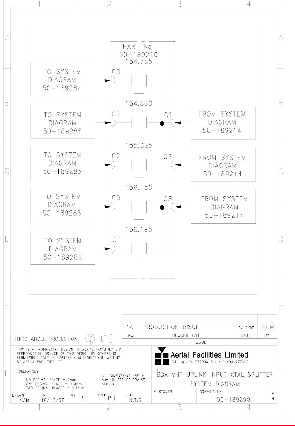
4.4. BDA VHF Uplink Input Splitter (50-189210)
BDA VHF Uplink Input Splitter (50-189210) takes the three signal path inputs from the first stage
uplink cavity filter in rack 2 and splits two of the signals to produce five signal paths which are then
fed to the crystal filters.
The outputs from the five crystal filters then leave the Uplink Input Splitter shelf to go to the uplink
sections of the Channelised Amplifier shelves.
This is a passive shelf and has no connection to the PSU and no alarms,
4.4.1. BDA VHF Uplink Input Splitter (50-189210) Major Components
Component
Part
Component Part Description Qty Per
Assembly
19-000822K 2U Rack Mount Chassis 1
93-980196 Crystal Filter 154.785MHz 1
93-980225 Crystal Filter 154.830MHz 1
93-980227 Crystal Filter 155.325MHz 1
93-980228 Crystal Filter 156.150MHz 1
93-980229 Crystal Filter 156.195MHz 1
Top View – lid removed
Close-up
of connectors
A Port G3 Input from cavity combiner
B Port G1 Input from cavity combiner
C Port C4 U/L Channel 4 output
D Port C2 U/L Channel 2 output
E Port G1 Input from cavity combiner
F Port C5 U/L Channel 5 output
G Port C3 U/L Channel 3 output
H Port C1 U/L Channel 1 output
5 Ch. VHF Radio Repeater Equipment
Document Number 50-189201HBK – Issue 1 Page 16 of 48
4.4.2. BDA VHF Uplink Input Splitter (50-189210) System diagram
Drawing number 50-189290

5 Ch. VHF Radio Repeater Equipment
Document Number 50-189201HBK – Issue 1 Page 17 of 48
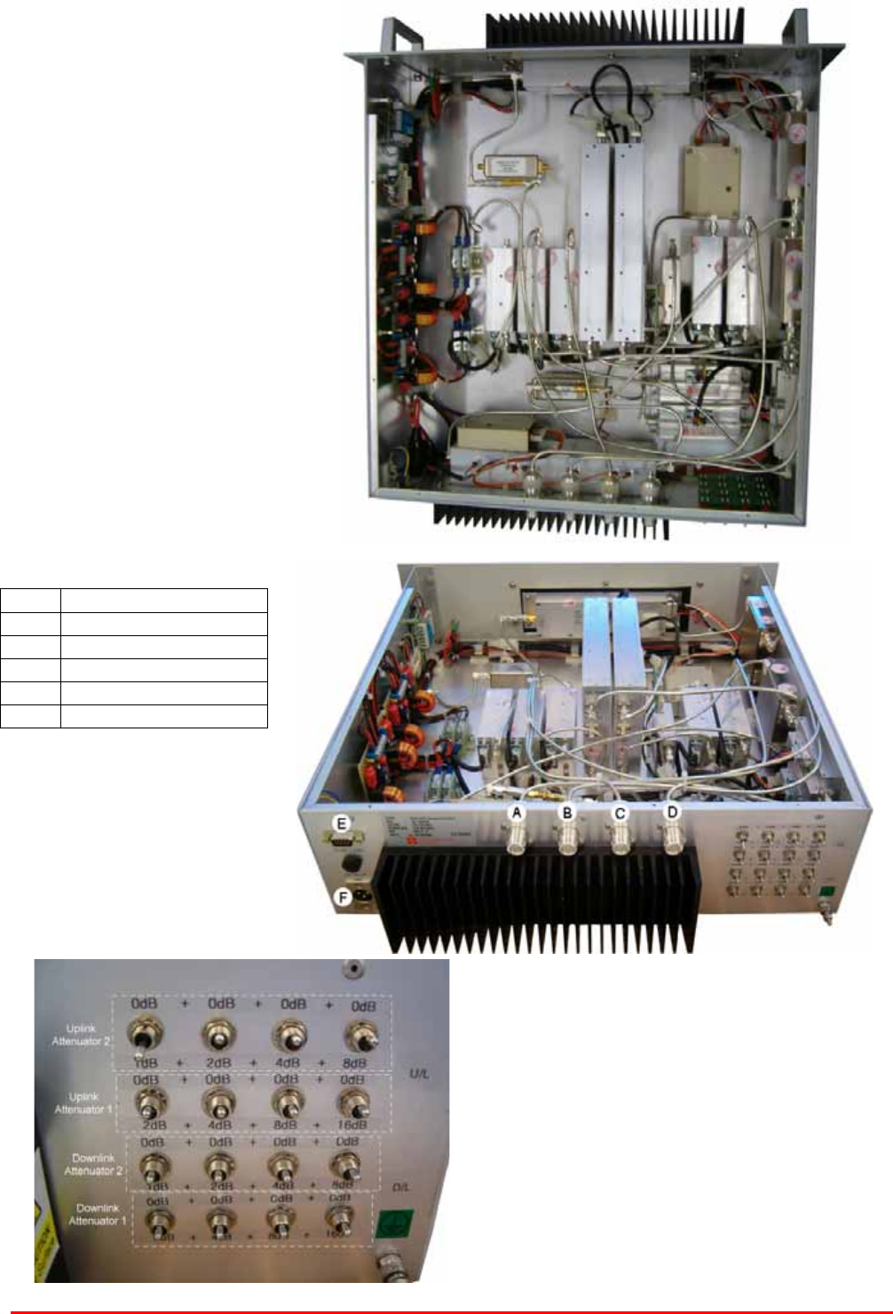
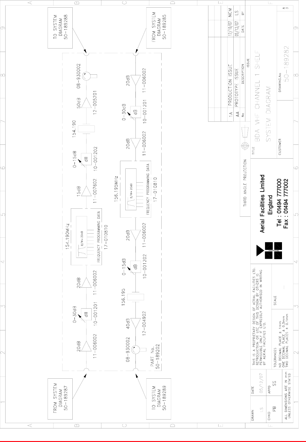
4.5. BDA VHF Channel Shelves (50-189202 to 50-189206)
Rack 1 contains five Channelised Amplifier shelves, one shelf for each channel.
Each shelf is composed of identical sub-modules, the only differences being the frequency that the
modules are configured to pass and the part numbers of the crystal filters employed.
Each shelf is powered by a 24V DC feed from the PSU (50-146512) and has alarm outputs.
Shelf 1, 50-189202, passes channel 1
Shelf 2, 50-189203, passes channel 2
Shelf 3, 50-189204, passes channel 3
Shelf 4, 50-189205, passes channel 4
Shelf 5, 50-189206, passes channel 5
In the downlink direction, signals are received from the Downlink Input Splitter (50-189207) and pass
through a low noise amplifier, one of the two switched attenuators and a second LNA. After the
second LNA the signal passes into the channel selectivity module and then into a third LNA. After
vthe third LNA the passes through the second switched attenuator and then into a crystal filter which
further defines the operating frequency. After the crystal filter the signal passes through a 10W power
amplifier and then a ferrite isolator which provides isolation from reflected uplink signals. After passing
through the ferrite isolator the signal leaves the Channelised Amplifier shelf and enters the Downlink
Output Combiner (50-189208)
In the uplink direction, signals are received from the Uplink Input Splitter (50-189210) and pass
through a low noise amplifier, one of the two switched attenuators and a second LNA. After the
second LNA the signal passes into the channel selectivity module and then into a third LNA. After
vthe third LNA the passes through the second switched attenuator and then into a crystal filter which
further defines the operating frequency. After the crystal filter the signal passes through a 5W power
amplifier and then a ferrite isolator which provides isolation from reflected downlink signals. After
passing through the ferrite isolator the signal leaves the Channelised Amplifier shelf and enters the
Uplink Output Combiner (50-189209)
4.5.1. BDA VHF Channel Shelves Major Components
Parts common to all 5 shelves
Component
Part
Component Part Description Qty Per
Assembly
08-930002 2 Port Isolator 2
10-000701 Switched Attenuator 0-30dB 0.25W 2
10-000901 Switched Attenuator 0-15dB 0.25W 2
11-006002 LNA VHF 70-500MHz with Relay 5
11-007602 LNA 50-200MHz (HIGH IP3) 1
12-002201 3 Stage Amplifier Alarm Board 2
12-004902 Power Amplifier VHF 5W 1
12-005201 Power Amplifier VHF 10W 1
13-001803 Dual D/DC Convertor 24V-12V 1A 2
17-010810 VHF Channel Selectivity Module 2
19-000922KL 3U Rack Mount Chassis 1
20-001601 12V Relay PCB Assembly 1
80-008902 24V Relay PCB Assembly 1
80-008909 12V Relay PCB Assembly with LED 1

5 Ch. VHF Radio Repeater Equipment
Document Number 50-189201HBK – Issue 1 Page 18 of 48
Parts specific to Shelf 1, 50-189202
Component
Part
Component Part Description Qty Per
Assembly
93-980196 Crystal Filter 154.785MHz 1
93-980222 Crystal Filter 154.070MHz 1
Parts specific to Shelf 2, 50-189203
Component
Part
Component Part Description Qty Per
Assembly
93-980223 Crystal Filter 154.190MHz 1
93-980225 Crystal Filter 154.830MHz 1
Parts specific to Shelf 3, 50-189204
Component
Part
Component Part Description Qty Per
Assembly
93-980226 Crystal Filter 155.700MHz 1
93-980227 Crystal Filter 155.325MHz 1
Parts specific to Shelf 4, 50-189205
Component
Part
Component Part Description Qty Per
Assembly
93-980228 Crystal Filter 156.150MHz 1
93-980230 Crystal Filter 158.850MHz 1
Parts specific to Shelf 5, 50-189205
Component
Part
Component Part Description Qty Per
Assembly
93-980229 Crystal Filter 156.195MHz 1
93-980231 Crystal Filter 158.910MHz 1
5 Ch. VHF Radio Repeater Equipment
Document Number 50-189201HBK – Issue 1 Page 19 of 48
Top View – lid removed
A Downlink Input
B Downlink Output
C Uplink Input
D Uplink Output
E Alarm Output
F DC Input (24V)
Close-up of attenuator switches
5 Ch. VHF Radio Repeater Equipment
Document Number 50-189201HBK – Issue 1 Page 20 of 48
4.5.2. BDA VHF Channel 1 Shelf (50-189202) System diagram
Drawing number 50-189282
5 Ch. VHF Radio Repeater Equipment
Document Number 50-189201HBK – Issue 1 Page 21 of 48
4.5.3. BDA VHF Channel 2 Shelf (50-189203) System diagram
Drawing number 50-189283

5 Ch. VHF Radio Repeater Equipment
Document Number 50-189201HBK – Issue 1 Page 22 of 48
4.5.4. BDA VHF Channel 3 Shelf (50-189204) System diagram
Drawing number 50-189284
5 Ch. VHF Radio Repeater Equipment
Document Number 50-189201HBK – Issue 1 Page 23 of 48
4.5.5. BDA VHF Channel 4 Shelf (50-189205) System diagram
Drawing number 50-189285

5 Ch. VHF Radio Repeater Equipment
Document Number 50-189201HBK – Issue 1 Page 24 of 48
4.5.6. BDA VHF Channel 5 Shelf (50-189206) System diagram
Drawing number 50-189286
5 Ch. VHF Radio Repeater Equipment
Document Number 50-189201HBK – Issue 1 Page 25 of 48
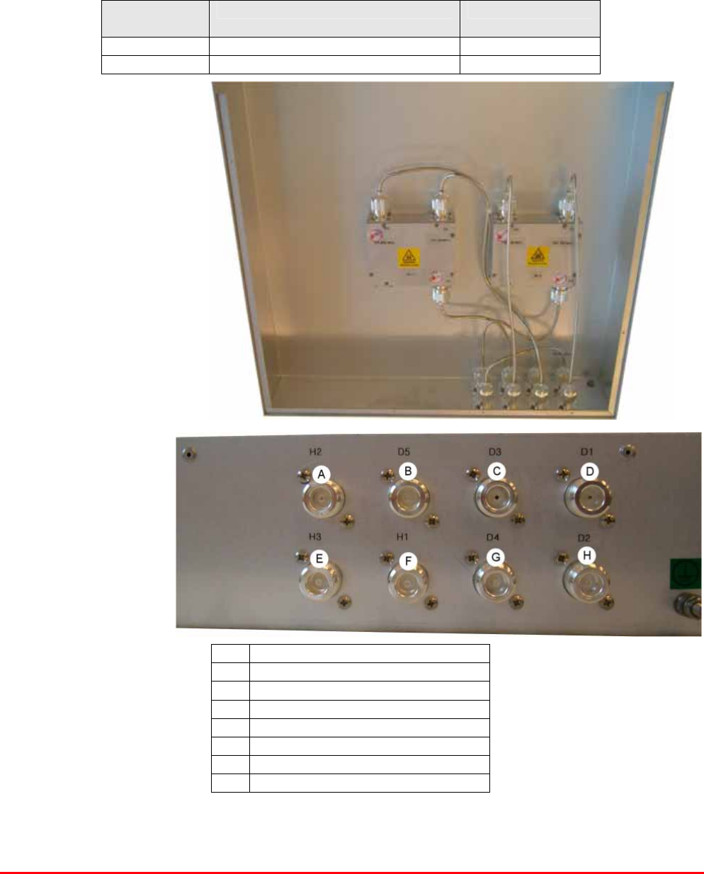
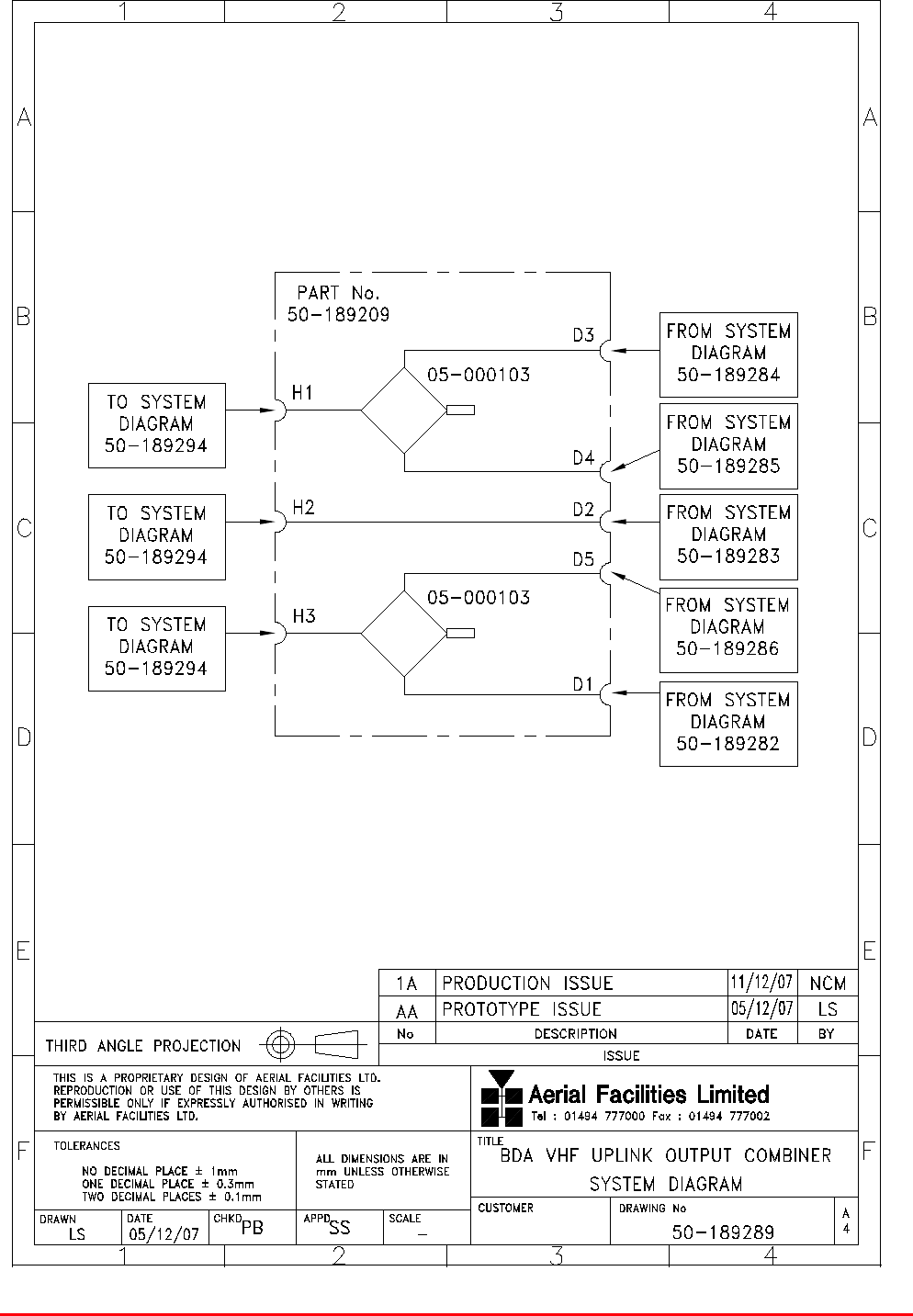
4.6. BDA VHF UPLINK OUTPUT COMBINER (50-189209)
The Uplink Output Combiner (50-189209) takes the five separate uplink outputs from the Channelised
Amplifier shelves and combines them into three signal paths Channels 3 and 4 are combined by a
Hybrid Combiner, Channels 5 and 1 are combined by a second Hybrid Combiner. Channel 2 passes
straight through. The three resultant outputs are then fed to the second stage of the cavity filter in
rack 3
4.6.1. BDA VHF Uplink Output Combiner (50-189209) Major Components
Component
Part
Component Part Description Qty Per Assembly
05-000103 Hybrid Combiner 2
19-000822K 2U Rack Mount chassis 1
Top View – lid removed
Close-up
of connectors
A Port H2 U/L Channel 2 output
B Port D5 U/L Channel 5 input
C Port D3 U/L Channel 3 input
D Port D1 U/L Channel 1 input
E Port H3 U/L Channel 1/5 output
F Port H1 U/L Channel 3/4 output
G Port D4 U/L Channel 4 input
H Port D2 U/L Channel 2 input
5 Ch. VHF Radio Repeater Equipment
Document Number 50-189201HBK – Issue 1 Page 26 of 48
4.6.2. BDA VHF Uplink Output Combiner (50-189209) System Diagram
Drawing number 50-189289
5 Ch. VHF Radio Repeater Equipment
Document Number 50-189201HBK – Issue 1 Page 27 of 48
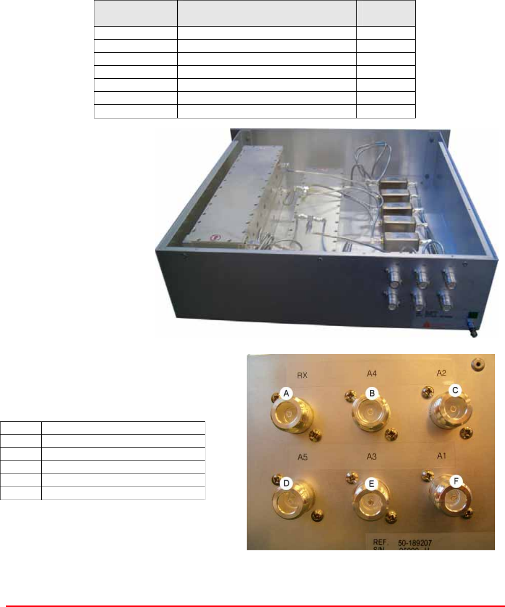
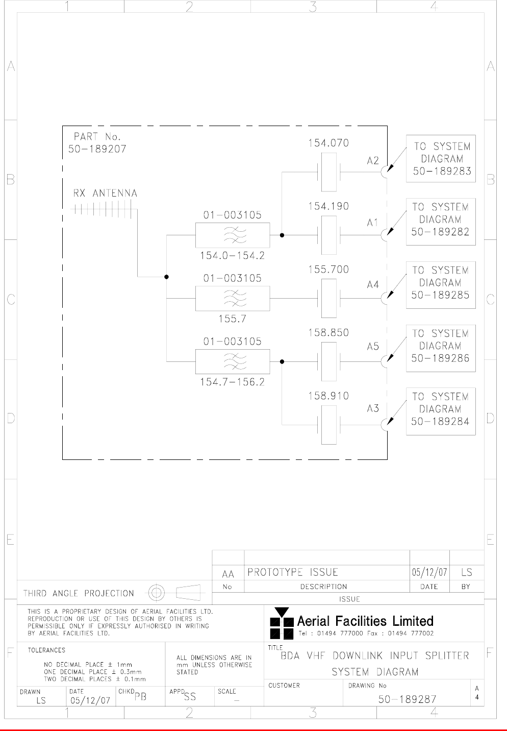
4.7. BDA VHF DOWNLINK INPUT SPLITTER (50-189207)
Downlink Input Splitter (50-189207) shelf receives Downlink VHF signals from the off-air RX antenna,
the signal is split into three paths and each path is then pased through a Bandpass Notch Filter. The
outputs of two of the filters are then further divided to produce the five required channels. Each
channel then passes through a Crystal Filter before leaving the Input Splitter shelf and going to a
dedicated Channelised Amplifier.
4.7.1. BDA VHF Downlink Input Splitter (50-189207) Major Components
Component
Part
Component Part Description Qty Per
Assembly
01-003105 Bandpass Notch Filter 3
19-000922K 3U Rack Mount Chassis 1
93-980222 Crystal Filter 154.070MHz 1
93-980223 Crystal Filter 154.190MHz 1
93-980226 Crystal Filter 155.700MHz 1
93-980230 Crystal Filter 158.850MHz 1
93-980231 Crystal Filter 158.910MHz 1
Top View – lid removed
Close-up of connectors
A Input from RX Antenna
B Port A4 U/L Channel 4 output
C Port A2 U/L Channel 2 output
D Port A5 U/L Channel 5 output
E Port A3 U/L Channel 3 output
F Port A1 U/L Channel 1 output
5 Ch. VHF Radio Repeater Equipment
Document Number 50-189201HBK – Issue 1 Page 28 of 48
4.7.2. BDA VHF Downlink Input Splitter (50-189207) System Diagram
Drawing number 50-189287
5 Ch. VHF Radio Repeater Equipment
Document Number 50-189201HBK – Issue 1 Page 29 of 48
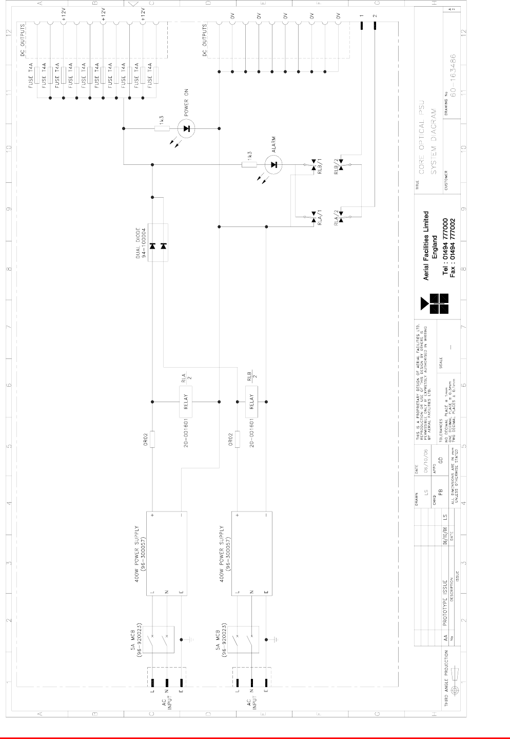
4.8. 24V PSU Shelf (50-146512)
The power supply shelf (50-146512) consists of two, 400Watt 24V DC, O.E.M modules which are
commonly supplied from the mains but separately switched. The DC outputs are separately monitored
and this data becomes half of the alarm data for the shelf (the two monitor loops are summed to form
a single alarm relay contact pair). A pair of low-loss power diodes combine the outputs from the PSU
modules in a redundant configuration such that if either module fails, the other supply would still be
active but the faulty supply DC LED on the front panel would be extinguished and the alarm loop
would be broken.
4.8.1. 24V PSU Shelf (50-146512) Specification
PARAMETER SPECIFICATION
Height: 5U
Width: 19" (482.6mm)
Shelf
dimensions: Depth: <450mm (excluding connectors & handles)
operational: -20°C to +60°C Temperature
range: storage: -40°C to +70°C
Weight: <10kg
Humidity: 95% RHNC
DC Output connectors: 6 x XLR female
DC Output Voltage: 24V DC (x 6)
24V DC O/P fuse rating: 10A (x 6)
Environmental protection: IP44
Alarms: PSU1 & 2 (‘D’ connector pins 1 & 2)
Case: Iridite NCP coat
Heatsinks: Black anodised aluminium
Handles: Silver anodised aluminium alloy
Finish
Fascia Painted to RAL7035
4.8.2. 24V PSU Shelf (50-146512) Major Components
Component Part Component Part Description Qty Per
Assembly
13-003301 Mains Filter Assembly 8 AMP 1
20-001601 12V Relay Board 1
80-008921 PSU 4U Rack mount chassis 1
93-510077 Aluminium Clad Resistor 0R02 50W 2
94-100004 60A DUAL DIODE 1
96-300054 24V 17A PSU 400W 2
96-700034 LED RED 5mm IP67 1
96-700035 LED GREEN 5mm IP67 2
96-920023 5A Circuit Breaker 2
5 Ch. VHF Radio Repeater Equipment
Document Number 50-189201HBK – Issue 1 Page 30 of 48
Top View – lid removed
A Fuses (PSU 1)
B 24V DC Outputs (PSU 1)
C Fuses (PSU 2)
D 24V DC Outputs (PSU 2)
E On/Off switch (PSU 1)
F On/Off switch (PSU 2)
G AC Input
H Alarm Output
I Ground Connection
5 Ch. VHF Radio Repeater Equipment
Document Number 50-189201HBK – Issue 1 Page 31 of 48
4.8.2. 24V PSU Shelf (50-146512) System Diagram
Drawing number 60-163486

5 Ch. VHF Radio Repeater Equipment
Document Number 50-189201HBK – Issue 1 Page 32 of 48
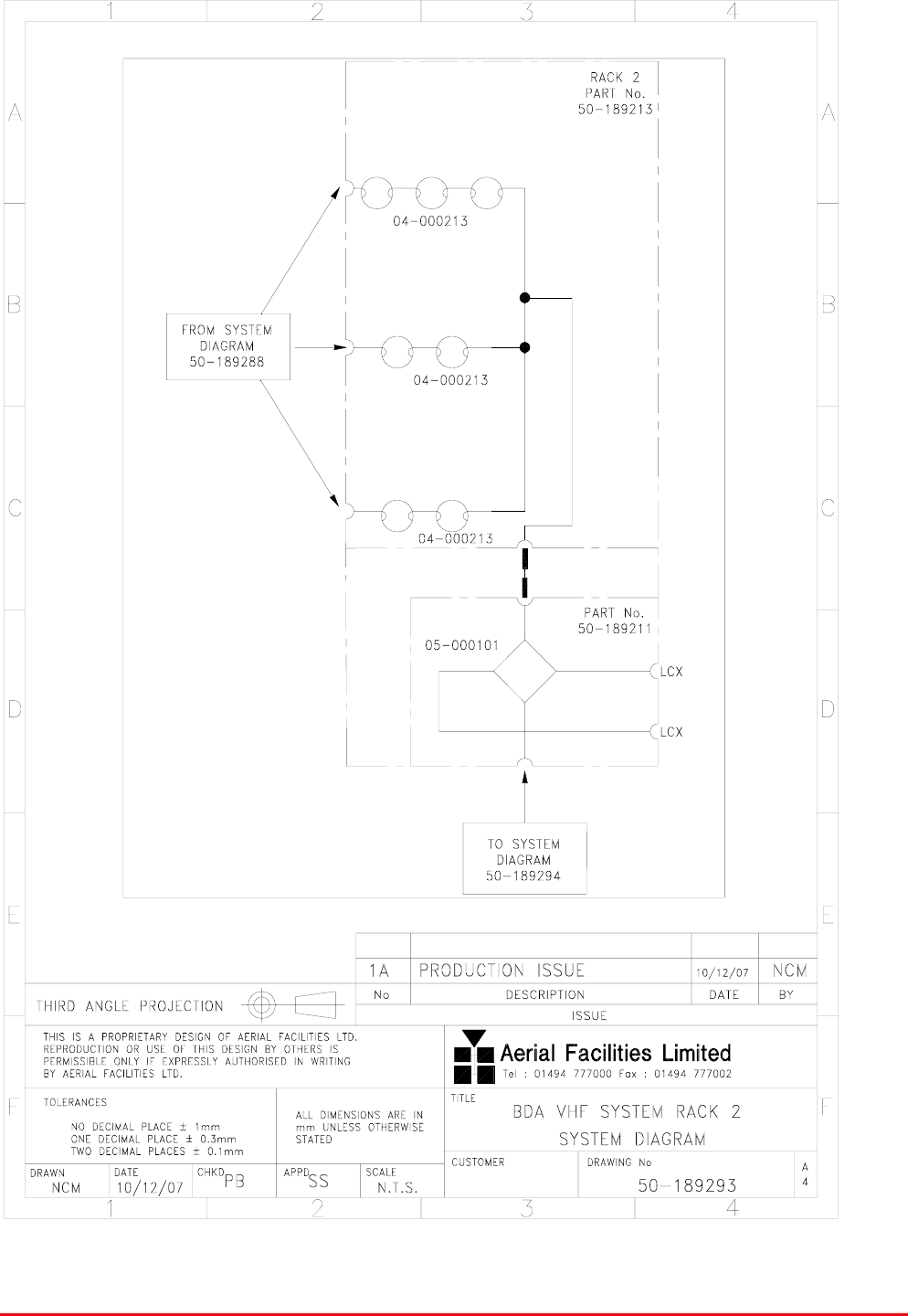
5. BDA VHF SYSTEM RACK 2 (50-189213)
Rack 2, the Downlink cavity combiner takes the three signals from Downlink Output Combiner (50-
189208) and passes each of them through a cavity filter stage, the combined D/L channels 1 & 2 are
passed through a chain of three cavitiy filters, D/L channel 4 and the combined D/L channels 3 & 5
are each passed through a chain of two cavity filters. The three signal paths are then combined by
means of a critical length harness into a single signal path which is fed into the Hybrid
Splitter/Combiner Tray (50-189211) where a Hybrid Splitter splits the signal into two paths, one each
for the two LCX feeds.
Rack 2 is a 43U equipment mounting rack (600mm x 600mm) and comprised of the following
modules, listed from the top of the rack
Component
Part
Component Part Description Qty Per
Assembly
50-189211 Hybrid Splitter/Combiner Tray 1
04-000213 VHF Cavity Resonator 7
5 Ch. VHF Radio Repeater Equipment
Document Number 50-189201HBK – Issue 1 Page 33 of 48
Rack Interconnections (see below)
A Three cavity filter section for combined D/L
channels 1 & 2
B Two cavity filter section for D/L channel 4
C Two cavity filter section for combined D/L
channels 3 & 5
D Hybrid Splitter/Combiner Tray (50-189211)
Rack interconnections are on the top of the rack rack
E1 D/L Channel 4 from Rack 1
E2 Combined D/L Channel 1 & 2 from Rack 1
E3 Combined D/L Channel 3 & 5 from Rack 1
K1 Combined U/L feed to Rack 3
LCX Connection to LCX
LCX Connection to LCX
5 Ch. VHF Radio Repeater Equipment
Document Number 50-189201HBK – Issue 1 Page 34 of 48
5.1. BDA VHF System Rack 2 (50-189213) System Diagram
Drawing number 50-189293
5 Ch. VHF Radio Repeater Equipment
Document Number 50-189201HBK – Issue 1 Page 35 of 48
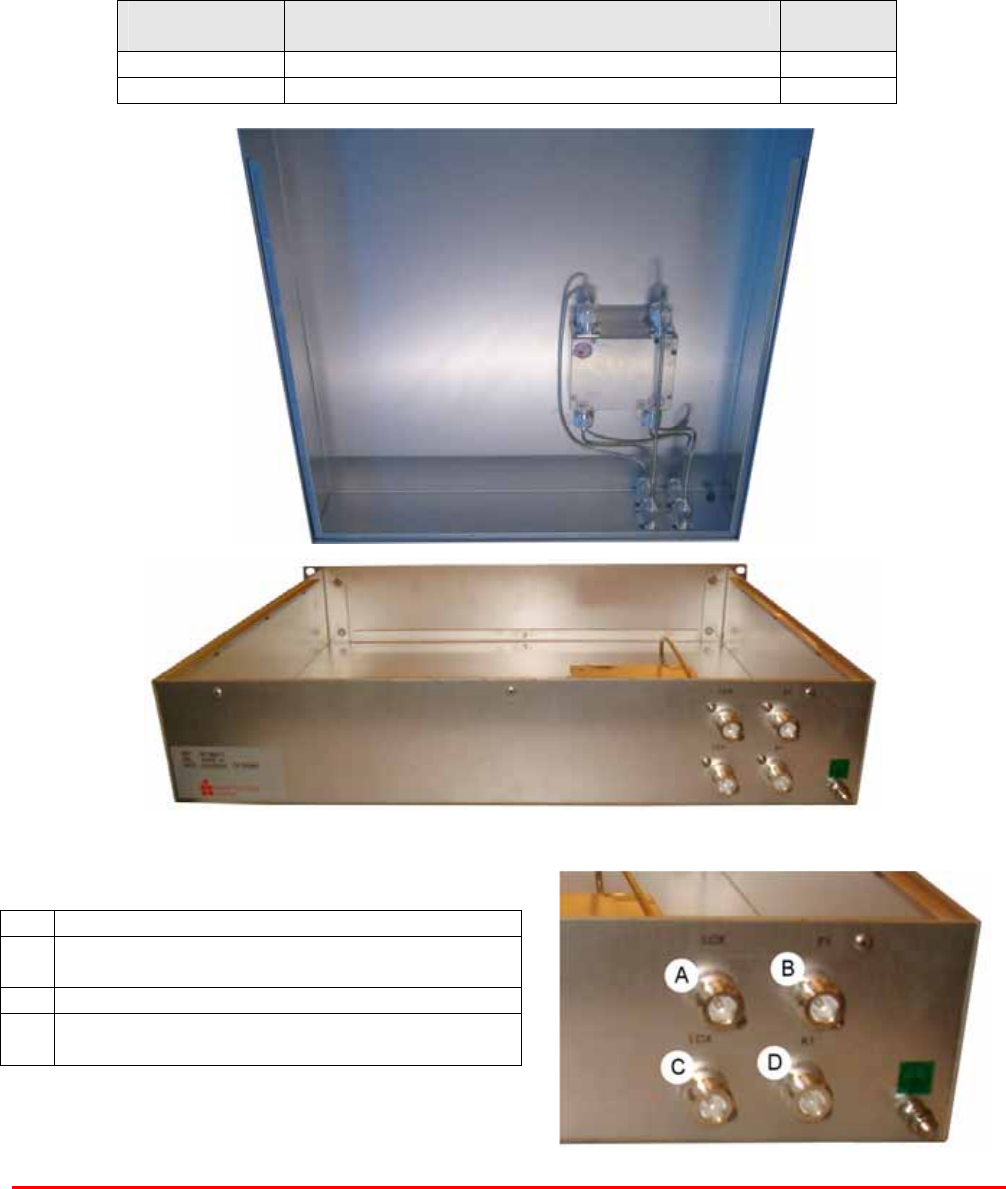
5.2. Hybrid Splitter/Combiner Tray (50-189211)
In the Downlink direction the Hybrid Splitter/Combiner Tray (50-189211) receives the downlink signal
from the Downlink Cavity Combiner and splits it into two separate signal paths to provide the two LCX
feeds
In the Uplink direction the Hybrid Splitter/Combiner Tray (50-189211) takes the two seperate LCX
feeds and combines them before passing the signal on to Uplink Input Splitter (50-189210) In rack 1
5.2.1. Hybrid Splitter/Combiner Tray (50-189211) Major Components
Component
Part
Component Part Description Qty Per
Assembly
05-000101 Hybrid Splitter/Combiner 1
19-000822K 2U Rack Mount Chassis 1
Top view – lid removed
Close-up of connectors
A LCX 1 Connection
B Port F1 Combined D/L Input from
Cavity Combiner Rack 2
C LCX 2 Connection
D Port K1 Combined U/L Output to
First stage Cavity Combiner Rack 3
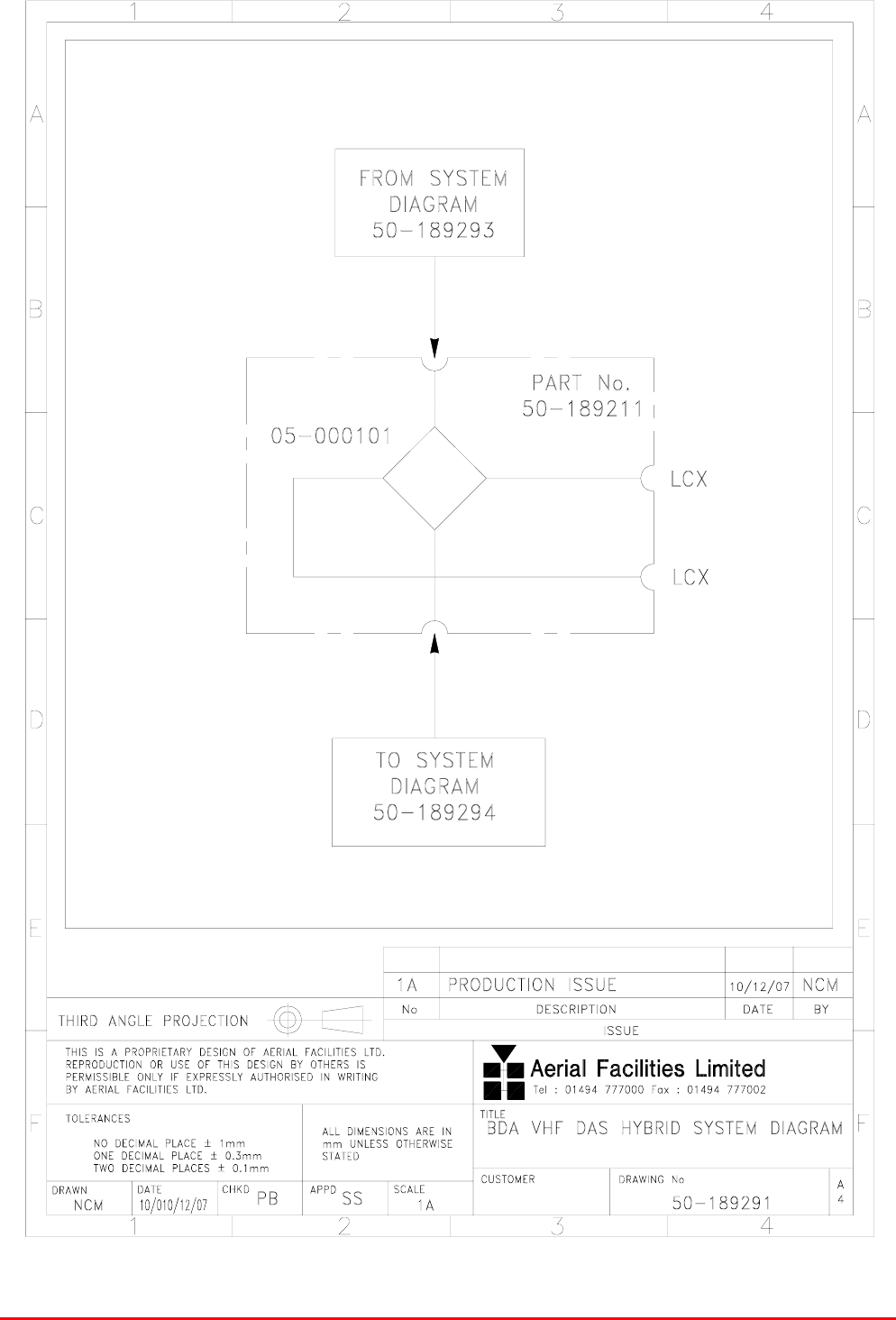
5 Ch. VHF Radio Repeater Equipment
Document Number 50-189201HBK – Issue 1 Page 36 of 48
5.2.2. Hybrid Splitter/Combiner Tray (50-189211) System Diagram

5 Ch. VHF Radio Repeater Equipment
Document Number 50-189201HBK – Issue 1 Page 37 of 48
6. BDA VHF SYSTEM RACK 3 (50-189214)
Rack 3, the Uplink Cavity Combiner comprises two stages.
Stage 1 takes the uplink feed from Hybrid Splitter/Combiner Tray (50-189211) in Rack 2 and by
means of critical length harnesses splits the signal into three paths, each path is then fed through a
chain of two cavity filters before being fed to the Uplink Input Splitter (50-189210) In rack 1
Stage 2 receives the three uplink signals from Uplink Output Combiner (50-189209) and by means of
critical length harnesses, combines the signals into a single path which is then routed through a
Bandpass Notch Filter before being fed to the TX antenna
Rack 3 is a 43U equipment mounting rack (600mm x 600mm) and comprised of the following
modules, listed from the top of the rack
Component
Part
Component Part Description Qty Per
Assembly
01-003105 Bandpass Notch Filter 1
04-000213 VHF Cavity Resonator 12
5 Ch. VHF Radio Repeater Equipment
Document Number 50-189201HBK – Issue 1 Page 38 of 48
Rack Interconnections (see below)
A First stage Cavity Combiner
B Second stage Cavity Combiner
C Bandpass Notch Filter
Rack interconnections are on the top of the rack rack
Ant Connection to TX Antenna
K1 Combined U/L feed from rack 2
G1 Combined U/L Channel 3 & 4 to Rack 1
G2 U/L Channel 2 to Rack 1
G3 Combined U/L Channel 1 & 5 to Rack 1
H1 Combined U/L Channel 3 & 4 from Rack 1
H2 U/L Channel 2 from Rack 1
H3 Combined U/L Channel 1 & 5 from Rack 1
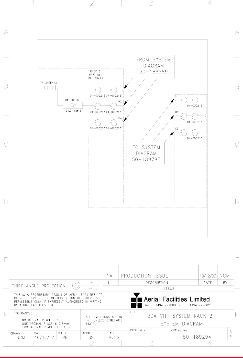
5 Ch. VHF Radio Repeater Equipment
Document Number 50-189201HBK – Issue 1 Page 39 of 48
6.1. BDA VHF System Rack 3 (50-189214) System Diagram

5 Ch. VHF Radio Repeater Equipment
Document Number 50-189201HBK – Issue 1 Page 40 of 48
7. INSTALLATION
7.1 Initial Installation Record
When this equipment is initially commissioned, please use the equipment set-up record sheet in
Appendix B. This will help both the installation personnel and AFL should these figures be needed for
future reference or diagnosis.
8. FAULT FINDING & MAINTENANCE
8.1 General Fault Finding Procedures
In the event that the performance of the system is suspect, a methodical and logical approach to the
problem will reveal the cause of the difficulty.
Transmissions from the main base stations are passed though the system to the mobile radio
equipment; this could be a handheld radio or a transceiver in a vehicle. This path is referred to as the
downlink. The return signal path from the mobile radio equipment to the base station is referred to as
the uplink.
The first operation is to check the alarms of each of the active units and determine that the power
supplies to the equipment are connected and active.
This can be achieved remotely (via CEMS, the RS232 Coverage Enhancement Management System,
if fitted), or locally with the front panel LEDs. The green LED on the front panel should be illuminated,
while the red alarm indicator should be off.
If an alarm is on, then that individual shelf/module must be isolated and individually tested against the
original test specification.
The individual amplifier units have a green LED showing through a hole in their case, which is
illuminated if the unit is working correctly.
If an amplifier is suspect, check the DC power supply to the unit. If no other fault is apparent use a
spectrum analyser to measure the incoming signal level at the input and then after reconnecting the
amplifier input, measure the output level. Consult with the system diagram to determine the expected
gain and compare result.
In the event that there are no alarms on and all units appear to be functioning it will be necessary to
test the system in a systematic manner to confirm correct operation.
8.2 Downlink
Confirm that there is a signal at the expected frequency and strength from the base station. If this is
not present then the fault may lay outside the system. To confirm this, inject a downlink frequency
signal from a known source at the master site BTS input and check for output at the remote site
feeder output.
If a signal is not received at the output it will be necessary to follow the downlink path through the
system to find a point at which the signal is lost. The expected downlink output for the given input can
be found in the end-to-end test specification.

5 Ch. VHF Radio Repeater Equipment
Document Number 50-189201HBK – Issue 1 Page 41 of 48
8.3 Uplink
Testing the uplink involves a similar procedure to the downlink except that the frequencies used are
those transmitted by the mobile equipment.
8.4 Fault repair
Once a faulty component has been identified, a decision must be made on the appropriate course to
carry out a repair. A competent engineer can quickly remedy typical faults such as faulty connections
or cables. The exceptions to this are cable assemblies connecting bandpass filter assemblies that are
manufactured to critical lengths to maintain a 50-ohm system. Care should be taken when replacing
cables or connectors to ensure that items are of the correct specification. The repair of component
modules such as amplifiers and bandpass filters will not usually be possible in the field, as they
frequently require specialist knowledge and test equipment to ensure correct operation. It is
recommended that items of this type are replaced with a spare unit and the faulty unit returned to AFL
for repair.
8.5 Checking service
Following the repair of any part of the system it is recommended that a full end-to-end test is carried
out in accordance with the test specification and that the coverage is checked by survey.
It is important to bear in mind that the system includes a radiating cable network and base stations
that may be faulty or may have been damaged.
8.6 Service Support
Advice and assistance with maintaining and servicing this system are available by contacting Aerial
Facilities Ltd.
8.7 Tools & Test Equipment
The minimum tools and test equipment needed to successfully service this AFL product are as
follows:-
Spectrum analyser: 100kHz to 2GHz (Dynamic range = 90dB).
Signal Generator: 30MHz to 2GHz (-120dBm to 0dBm o/p level).
Attenuator: 20dB, 10W, DC-2GHz, (N male – N female).
Test Antenna: Yagi or dipole for operating frequency.
Digital multi-meter: Universal Volt-Ohm-Amp meter.
Test cable x 2: N male – N male, 2M long RG214.
Test cable x 2: SMA male – N male, 1m long RG223.
Hand tools: Philips #1&2 tip screwdriver.
3mm flat bladed screwdriver.
SMA spanner and torque setter.

5 Ch. VHF Radio Repeater Equipment
Document Number 50-189201HBK – Issue 1 Page 42 of 48
8.8 General Maintenance Procedures
Many of the active modules contain semiconductor devices utilising MOS technology, which can be
damaged by electrostatic discharge. Correct handling of such modules is mandatory to ensure their
long-term reliability.
To prevent damage to a module, it must be withdrawn/inserted with care. The module may have
connectors on its underside, which might not be visible to the service operative.
8.9 Module Removal (LNAs, general procedure)
The following general rules should be followed to remove a module:
1 Remove power to the unit
2 Remove all visible connectors (RF, DC & alarm)
3 Release module retaining screws.
4 Slowly but firmly, pull the module straight out of its position. Take care not to twist/turn the
module during withdrawal. (When the module is loose, care may be needed, as there may be
concealed connections underneath).
8.10 Module Replacement (general)
1 Carefully align the module into its location then slowly push the module directly straight into its
position, taking care not to twist/turn it during insertion.
2 Reconnect all connectors, RF, alarm, power etc., (concealed connectors may have to be
connected first).
3 Replace retaining screws (if any).
4 Double-check all connections before applying power.
8.11 Power Amplifiers
1) Remove power to the unit. (Switch off at the mains/battery, or remove DC in connector)
2) Remove alarm wires from alarm screw terminal block or disconnect multi-way alarm
connector.
3) Carefully disconnect the RF input and output coaxial connectors (usually SMA)
4) If the amplifier to be removed has a heatsink attached, there may be several different ways it
can have been assembled. The most commonly used method, is screws through the front of the
heatsink to threaded screw holes (or nuts and bolts), into the amplifier within the main case. If the
heatsink is mounted on the rear of the main case (e.g., against a wall in the case of wall mounted
enclosures), then the fixing method for the heatsink will be from within the case, (otherwise the
enclosure would have to be removed from the wall in order to remove the heatsink).
When the heatsink has been removed, the amplifier may be unscrewed from the main casing by its
four corner fixings and gently withdrawn.
Fitting a new power amplifier module will be the exact reverse of the above.
Note: Do not forget to apply fresh heatsink compound to the heatsink/main case joint and also
between the amplifier and the main case.

5 Ch. VHF Radio Repeater Equipment
Document Number 50-189201HBK – Issue 1 Page 43 of 48
8.12 Low Power Amplifier Replacement
Disconnect the mains power supply and disconnect the 24V dc supply connector for the LPA.
Disconnect the RF input and output cables from the LPA.
Disconnect the alarm connector.
Remove the alarm monitoring wires from (D type connector) pins 9 and 10.
Remove the LPA module by removing the four retaining screws, replace with a new LPA module and
secure it with the screws.
Connect the RF cables to the LPA input and output connectors. Reconnect the wires to the alarm
board connector pins 9 and 10.
Reconnect the DC supply connector and turn the mains switch on.
Note: Tighten SMA connectors using only a dedicated SMA torque spanner. If SMA connectors are
over-tightened, irreparable damage will occur. . Do not use adjustable pliers to loosen/tighten SMA
connectors.
Also take care not to drop or knock the module as this can damage (or misalign in the case of tuned
passive modules) sensitive internal components. Always store the modules in an environmentally
friendly location
8.13 Module Transportation
To maintain the operation, performance and reliability of any module it must be stored and
transported correctly. Any module not installed in a whole system must be kept in an anti-static bag or
container. These bags or containers are normally identified by being pink or black, and are often
marked with an ESD label. Any module sent back to AFL for investigation/repair must be so
protected. Please contact AFL’s quality department before returning a module.

5 Ch. VHF Radio Repeater Equipment
Document Number 50-189201HBK – Issue 1 Page 44 of 48
APPENDIX A
A.1. Glossary of Terms used in this document
Repeater or
Cell Enhancer
A Radio Frequency (RF) amplifier which can simultaneously
amplify and re-broadcast Mobile Station (MS) and Base
Transceiver Station (BTS) signals.
Band Selective
Repeater
A Cell Enhancer designed for operation on a range of channels
within a specified frequency band.
Channel Selective
Repeater
A Cell Enhancer, designed for operation on specified channel(s)
within a specified frequency band. Channel frequencies may be
factory set or on-site programmable.
AC Alternating Current
AGC Automatic Gain Control
BBU Battery Backup Unit
BTS Base Transceiver Station
CEMS Coverage Enhanced Management System
C/NR Carrier-to-Noise Ratio
DC Direct Current
Downlink (D/L) RF signals TX from the BTS to the Master Site
FO Fibre Optic
GND Ground
ID Identification Number
LED Light Emitting Diode
LNA Low Noise Amplifier
LPA Low Power Amplifier
MOU Master Optical Unit
M.S. Mobile Station
MTBF Mean Time Between Failures
N/A Not Applicable
N/C No Connection
OFR On Frequency Repeater
OIP3 Output Third Order Intercept Point
P1dB 1dB Compression Point
PA Power Amplifier
RF Radio Frequency
RSA Receiver/Splitter Amplifier
RX Receiver
S/N Serial Number
TX Transmitter
Uplink (U/L) RF signals transmitted from the MS to the BTS
VSWR Voltage Standing Wave Ratio
WDM Wave division multiplex
5 Ch. VHF Radio Repeater Equipment
Document Number 50-189201HBK – Issue 1 Page 45 of 48
&$;&$%/(
&$;&$%/(
&$7&$%/(
&$%/(6
),%5(237,&&$%/(/,1.
&$%/(
5$',$7,1*&$%/(
7$33(5&283/(5
67$7,21
%$6(75$16&(,9(5
0,6&
+8%6
),%5(0$,1+8%
(;3$16,21+8%
%,',5(&7,21$/$03/,),(5
(
%76
)0+
(+
',$
',$
G%',5(&7,21$/&283/(5
G%&283/(5
&
&5266%$1'&283/(5
&283/(56
- -803(5
&
& G%',5(&7,21$/&283/(5
G%',5(&7,21$/&283/(5
',5(&7,21$/&283/(5
3$1(/$17(11$
02817('$7+,*+/(9(/
',5(&7,21$/$17(11$
)/$73/$7($17(11$
<$*,$17(11$
$17(11$6
5(027($17(11$81,7
201,$17(11$
63/,77(56
$17(11$
5$8
%$1'3$66),/7(5
&$9,7<5(621$725
127&+),/7(5
,62/$725
+<%5,'&20%,1(5
($57+678'
/((.<)(('(5
2XWSXWVWRUHFHLYHUV
56$
$03/,),(5
0,6&
G% $77(18$7259$5,$%/(
$*&
$*& G%
&21752//(5
021,725,1*
02'(0
021,725,1*&21752//(5
02'(0
&(//(1+$1&(5
)5(48(1&<352*5$00,1*
'$7$
%: WRN+]
&+$11(/02'8/(
),%5(237,&
02'8/$725
),%5(237,&
'(02'8/$725
/2&$/26&,//$725
XSWR
ZD\
2XWSXWV
'800</2$'
/2&$/26&,//$725
63/,77(5
0,6&
),%5(237,&&$%/(/,1.
67$1'$5')25
/(9(/G%P
%(/2:$&&(37$%/(
6,*1$//(9(/G%P
$//$,532576
%&&+%52$'&$67
,'(17,7<&2'(
%6,&%$6,&6,7(
/(9(/G%P
%(/2:$&&(37$%/(
6,*1$//(9(/G%P
$&&(37$%/(6,*1$/
$&&(37$%/(6,*1$/
&21752/&+$11(/
5($',1*326,7,21
6,*1$/.(<
67$1'$5'(;&(37
)25$,532576
6((%(/2:
%/$'($17(11$
$77(18$725),;('
G%
287,1
&283/('
+, &20
/2:
+<%5,'63/,77(5
,1
,1
287
287
,1
287
%<'$7('(6&5,37,211R
7+,5'$1*/(352-(&7,21
$
%
&
'
(
)
$
%
&
'
(
)D[
7HO
$HULDO)DFLOLWLHV/LPLWHG
7+,6,6$35235,(7$5<'(6,*12)$(5,$/)$&,/,7,(6/7'
5(352'8&7,212586(2)7+,6'(6,*1%<27+(56,6
3(50,66,%/(21/<,)(;35(66/<$87+25,6(',1:5,7,1*
%<$(5,$/)$&,/,7,(6/7'
12'(&,0$/3/$&(sPP
21('(&,0$/3/$&(sPP
7:2'(&,0$/3/$&(6sPP
$//',0(16,216$5(,1PP
81/(6627+(5:,6(67$7('
&+.'
'5$:1
$33'
'$7(
72/(5$1&(6 6&$/(
(QJODQG
90-000001
AA
NTS
PL 10/05/00
25,*,1$/
,668(
3/
3/%/$'($17(11$$''('$
$ (&1
5)
5)
3/8*62&.(7
),%5(237,&
&211(&725
)&$3&
62&.(7
3/8*
0,6&
'&
'&
$&72'&368
'&72'&
&219(57(5
)86(
5(/$<
12&/($5&217$&7
1&),//('&217$&7
&20
0% *'
3/
% 7(;7&255(&7,21 3/
,668(
)
&86720(5'5$:,1*1R
7,7/(
$
AFL - STANDARD SYMBOLS
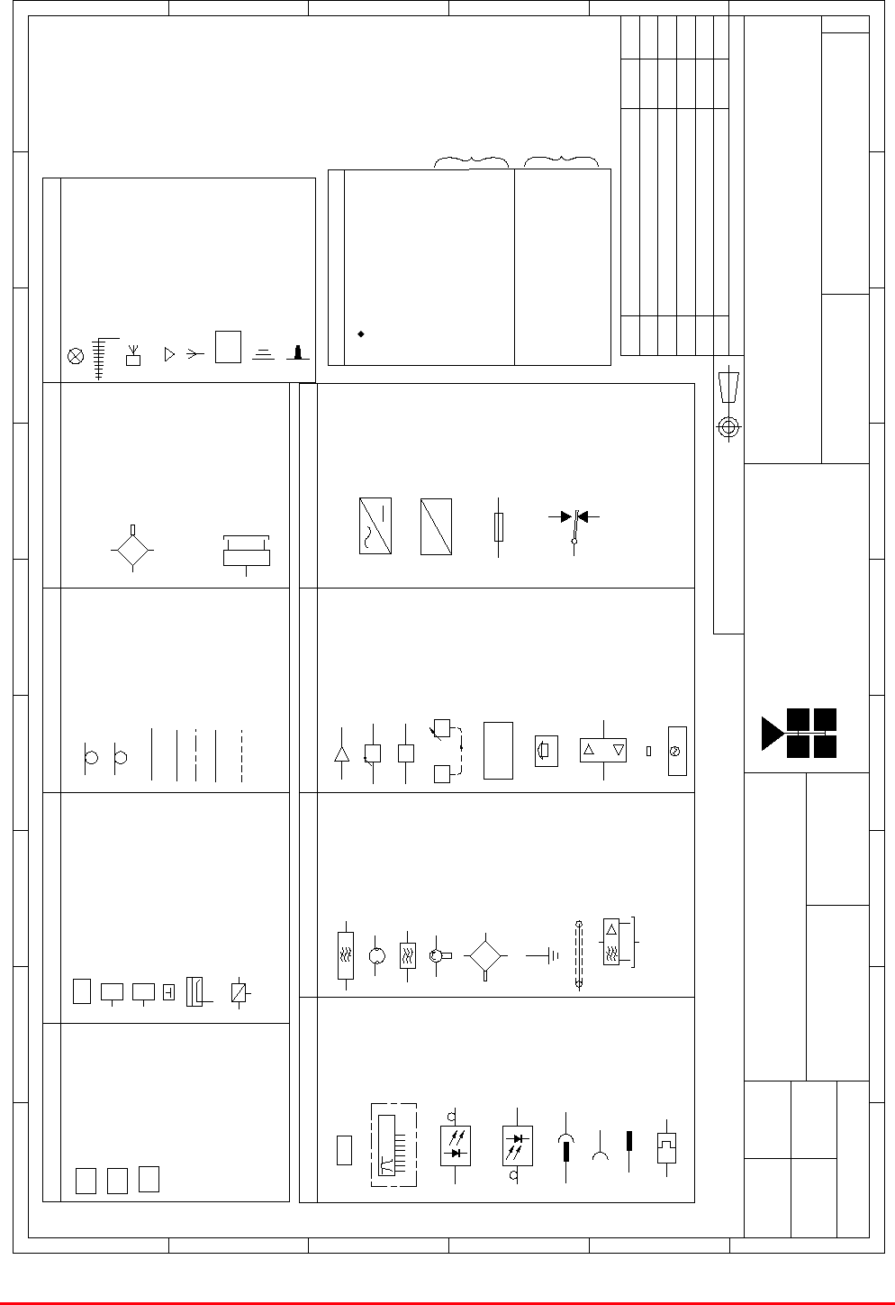
A.2. Key to Drawing Symbols used in this document

5 Ch. VHF Radio Repeater Equipment
Document Number 50-189201HBK – Issue 1 Page 46 of 48
Aerial Facilities Limited
A.3. EC Declaration of Conformity
In accordance with BS EN ISO/IEC 17050-1&-2:2004
Aerial Facilities Limited
Aerial House
Asheridge Road
Chesham
Buckinghamshire HP5 2QD
United Kingdom
DECLARES, UNDER OUR SOLE RESPONSIBILITY THAT THE FOLLOWING PRODUCT:
PRODUCT PART NO[S] 50-189201
PRODUCT DESCRIPTION 5 Channel VHF System 80dB
IN ACCORDANCE WITH THE FOLLOWING DIRECTIVES:
1999/5/EC The Radio & Telecommunications Terminal Equipment Directive Annex V
and its amending directives
HAS BEEN DESIGNED AND MANUFACTURED TO THE FOLLOWING STANDARD[S]
OR OTHER NORMATIVE DOCUMENT[S]:
BS EN 60950 Information technology equipment.
Safety. General requirements
ETS EN 301 489-1 EMC standard for radio equipment and services.
Part 1. Common technical requirements
I hereby declare that the equipment named above has been designed to comply with the relevant sections
of the above referenced specifications. The unit complies with all essential requirements of the Directives.
SIGNED
B S BARTON
TECHNICAL DIRECTOR DATE: 22/11/2007
Registered Office: Aerial House, Asheridge Road, Chesham, Buckinghamshire, HP5 2QD England Registered No. 4042808 (England)
www.aerialfacilities.com

5 Ch. VHF Radio Repeater Equipment
Document Number 50-189201HBK – Issue 1 Page 47 of 48
A.4. Amendment List Record Sheet
Document Ref. 50-189201HBK
Issue
No.
Date Incorporated
by
Page Nos.
Amended
Reason for new issue
A 05/12/2007 AJS Draft
1 21/12/2007 AJS First Issue
5 Ch. VHF Radio Repeater Equipment
Document Number 50-189201HBK – Issue 1 Page 48 of 48
APPENDIX B
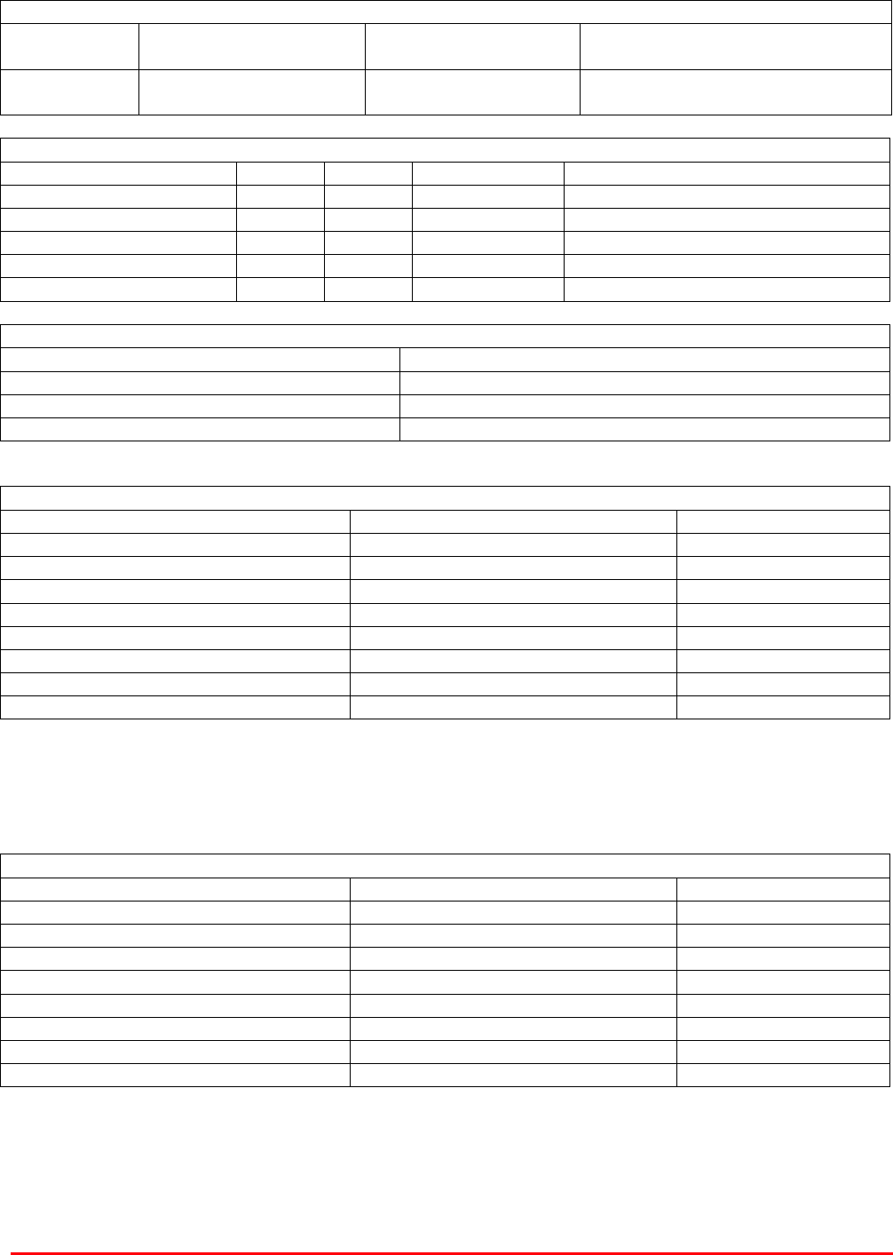
Initial Equipment Set-Up Calculations
General Information
Site Name: Client Name:
Date: AFL Equip. Model No.
Antenna Systems
Model Gain Azimuth Comments
A - Service Antenna
B – Donor Antenna
Type Loss Length Comments
C – Service Feeder
D – Donor Feeder
Initial Parameters
E – CE Output Power dBm
F – Antenna Isolation dB
G – Input signal level from donor BTS dBm
Operating Voltage V
Downlink Calculations
Parameter Comments Value
Input signal level (G) dBm
CE max. o/p power (E) dBm
Gain setting E - G dB
Isolation required (Gain + 10dB) dB
Service antenna gain (A) dB
Service antenna feeder loss (C) dB
Effective radiated power (ERP) E+A-C dBm
Attenuator setting CE gain-gain setting dB
If the input signal level in the uplink path is known and steady, use the following calculation table to
determine the gain setting. If the CE features Automatic Gain Control the attenuator should be set to
zero and if not, then the attenuation setting for both uplink and downlink should be similar.
Uplink Calculations
Parameter Comments Value
Input signal level dBm
CE max. o/p power (E) dBm
Gain setting dB
Required isolation dB
Donor antenna gain (B) dB
Donor antenna feeder loss (D) dB
Effective radiated power (ERP) E+B-D dBm
Attenuator setting (CE gain-gain setting) dB