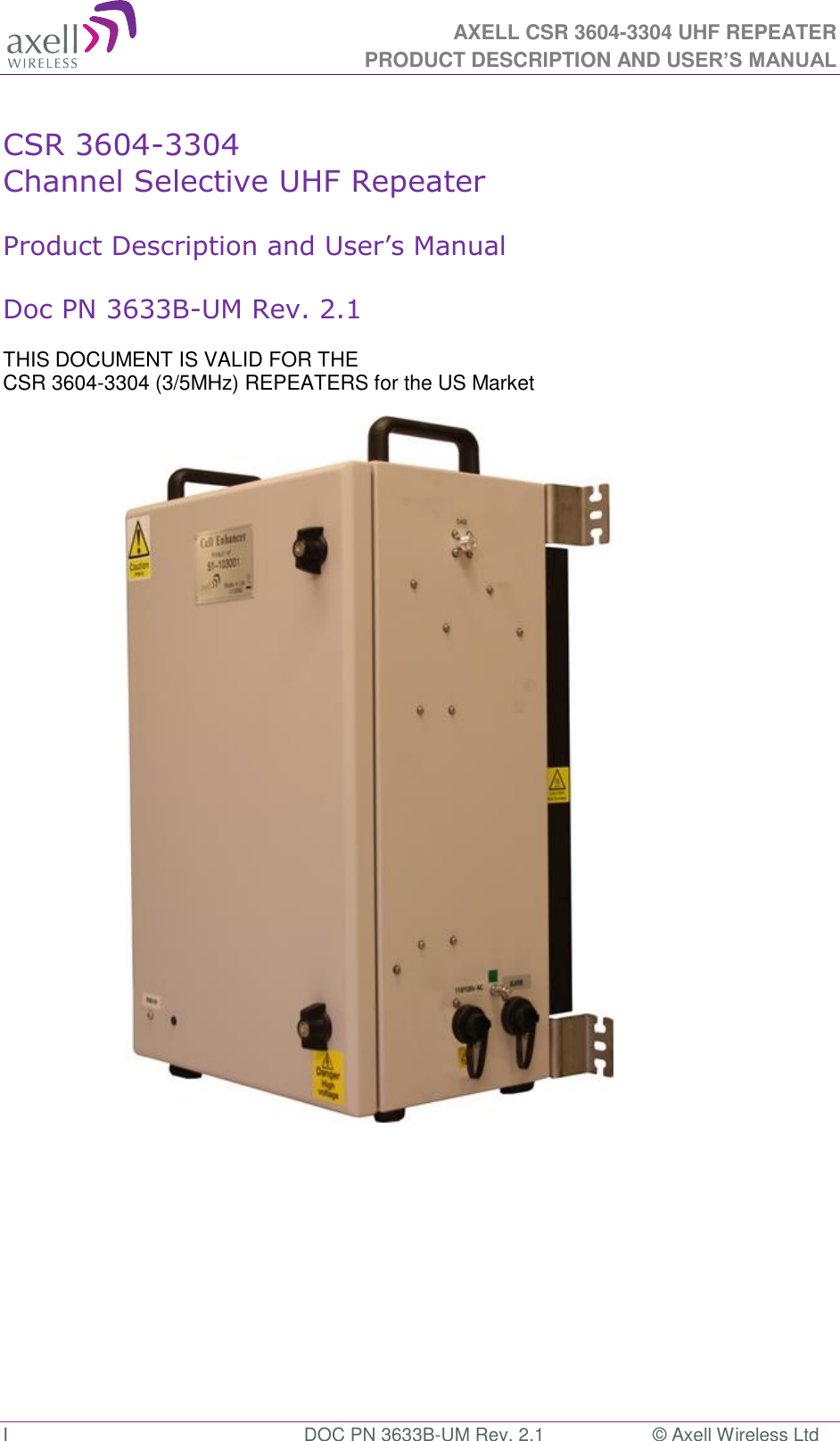
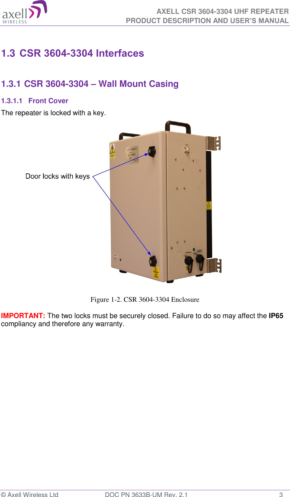
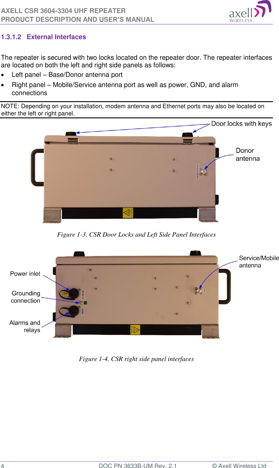
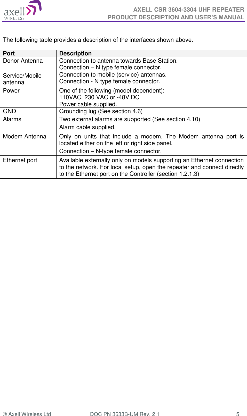
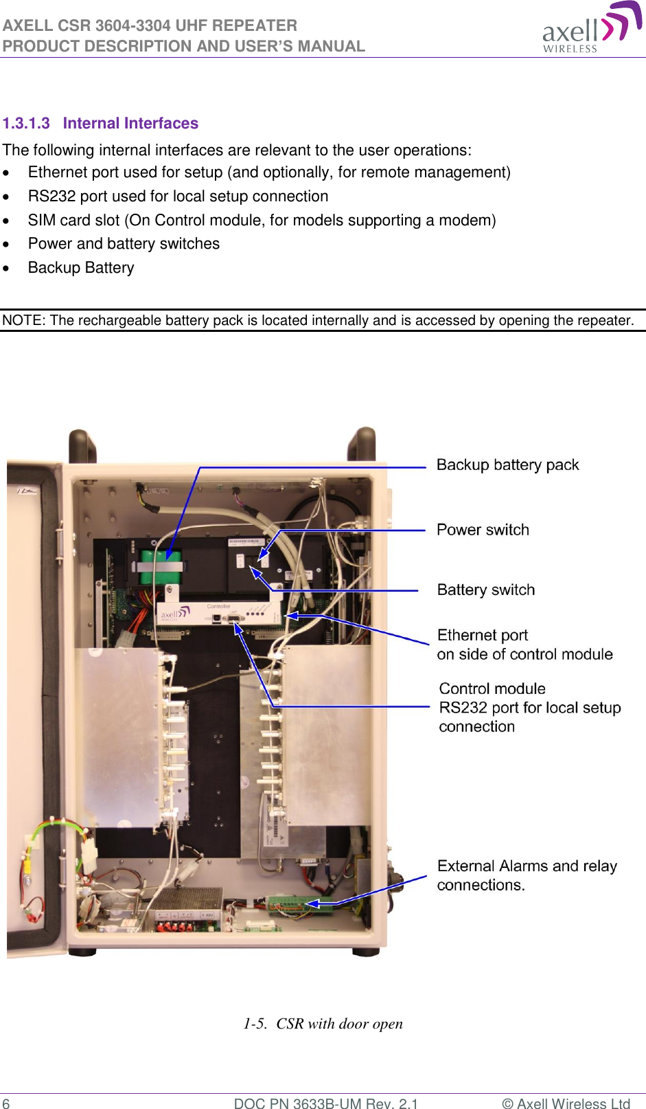
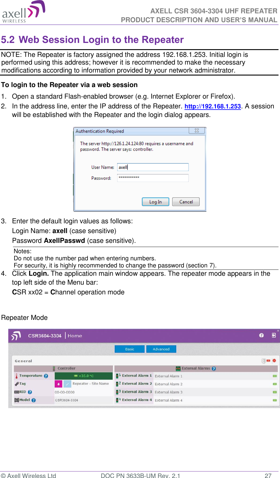
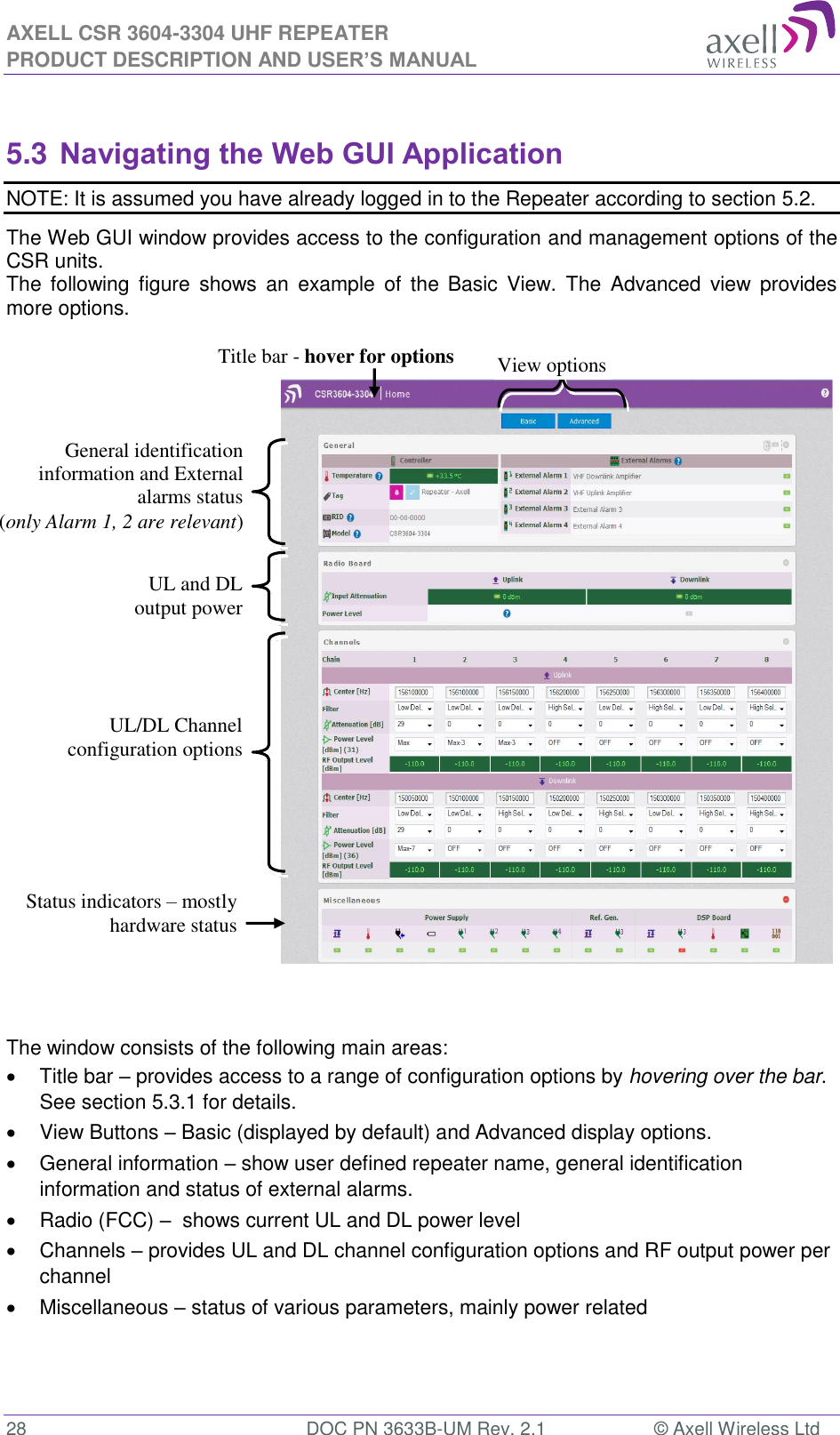
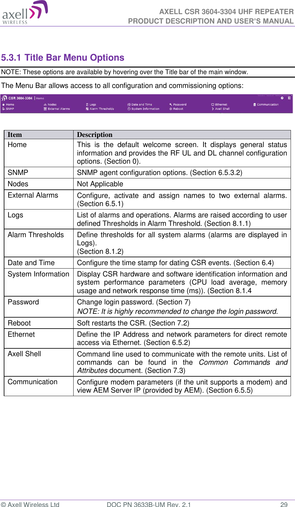
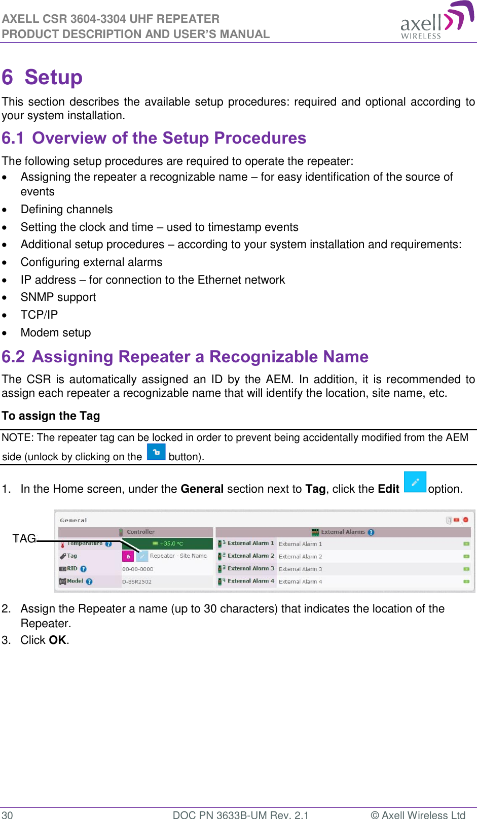
PBE Europe as Axell Wireless 51-101SERIES D-CSR-4004-8-450-470-DP-AC Selective Repeater User Manual CSR 3604 3304

Axell Wireless D-CSR-4004-8-450-470-DP-AC Selective Repeater CSR 3604 3304

Manual

 AXELL CSR 3604-3304 UHF REPEATER PRODUCT DESCRIPTION AND USER’S MANUAL  I  DOC PN 3633B-UM Rev. 2.1  © Axell Wireless Ltd  CSR 3604-3304  Channel Selective UHF Repeater   Product Description and User’s Manual  Doc PN 3633B-UM Rev. 2.1  THIS DOCUMENT IS VALID FOR THE  CSR 3604-3304 (3/5MHz) REPEATERS for the US Market
AXELL CSR 3604-3304 UHF REPEATER PRODUCT DESCRIPTION AND USER’S MANUAL © Axell Wireless Ltd  DOC PN 3633B-UM Rev. 2.1  II Copyright © 2014 Axell Wireless Ltd All rights reserved. No part of this document may be copied, distributed, transmitted, transcribed, stored in a retrieval  system,  or  translated  into  any  human  or  computer  language  without  the  prior written permission of Axell Wireless Ltd. The manufacturer has  made  every effort  to  ensure that  the  instructions contained in  this document  are  adequate  and  free  of  errors  and  omissions.  The  manufacturer  will,  if necessary, explain issues which may not be covered by this document. The manufacturer's liability  for  any  errors  in  the  document  is  limited  to  the  correction  of  errors  and  the aforementioned advisory services. This  document  has  been  prepared  to  be  used  by  professional  and  properly  trained personnel,  and  the  customer  assumes  full  responsibility  when  using  them.  The manufacturer  welcomes  customer  comments  as  part  of  the  process  of  continual development  and  improvement  of  the  documentation  in  the  best  way  possible  from  the user's  viewpoint.  Please  submit  your  comments  to  the  nearest  Axell  Wireless  sales representative. Contact Information Headquarters Axell Wireless Aerial House  Asheridge Road  Chesham  Buckinghamshire HP5 2QD  United Kingdom   Tel: +44 1494 777000  Fax: +44 1494 777002   Commercial inquiries info@axellwireless.com Web site www.axellwireless.com Support issues support@axellwireless.com Technical Support Line, English speaking +44 1494 777 747  Contact information for Axell Wireless offices in other countries can be found on our web site, www.axellwireless.com
 AXELL CSR 3604-3304 UHF REPEATER PRODUCT DESCRIPTION AND USER’S MANUAL  III  DOC PN 3633B-UM Rev. 2.1  © Axell Wireless Ltd About This Manual This Product Manual provides the following information:   Description of the Repeater    Procedures for setup, configuration and checking the proper operation of the Repeater    Maintenance and troubleshooting procedures   Users This Product Manual is intended for experienced technicians and engineers. It is assumed that  the  customers  installing,  operating,  and  maintaining  Axell  Wireless  Repeaters  are familiar with the basic functionality of Repeaters.  Notice Confidential - Authorized Customer Use This  document  may  be  used  in  its  complete form  only  and  is  solely  for  the  use  of  Axell Wireless  employees  and  authorized  Axell  Wireless  channels  or  customers.  The  material herein is proprietary to Axell Wireless. Any unauthorized reproduction, use or disclosure of any part thereof is strictly prohibited. All trademarks and registered trademarks are the property of their respective owners.  Disclaimer of Liability Contents herein are current as of the date of publication. Axell Wireless reserves the right to change the contents without prior notice. The information furnished by Axell Wireless in this document  is  believed  to  be  accurate  and  reliable.  However,  Axell  Wireless  assumes  no responsibility for its use. In no event shall Axell Wireless be liable for any damage resulting from loss of data, loss of use, or loss of profits and Axell Wireless further disclaims any and all  liability  for  indirect,  incidental,  special,  consequential  or  other  similes  damages.  This disclaimer of liability applies to all products, publications and services during and after the warranty period.  Safety to Personnel   Before installing or replacing any of the equipment, the entire manual should be read and understood.   This equipment is to be installed only in a restricted access location.   Throughout this manual, there are "Caution" warnings. "Caution" calls attention to a procedure or practice, which, if ignored, may result in injury or damage to the system, system component or even the user. Do not perform any procedure preceded by a "Caution" until the described conditions are fully understood and met.  CAUTION! This  notice  calls  attention  to  a  procedure  or  practice that, if ignored, may result in personal injury or in damage to the system  or  system  component.  Do  not  perform  any  procedure preceded  by  a  "Caution"  until  described  conditions  are  fully understood and met.
AXELL CSR 3604-3304 UHF REPEATER PRODUCT DESCRIPTION AND USER’S MANUAL © Axell Wireless Ltd  DOC PN 3633B-UM Rev. 2.1  IV Compliance with FCC  Part 90 Signal Boosters             THIS IS A 90.219 CLASS A DEVICE    WARNING: This is NOT a CONSUMER device. This device is designed for installation by FCC LICENCEES and QUALIFIED INSTALLERS. You MUST have an FCC LICENCE or express consent of an FCC Licensee to operate this device.  You MUST register Class B signal boosters (as defined in 47 CFR 90.219) online at www.fcc.gov/signal-boosters/registration.  Unauthorized use may result in significant forfeiture penalties, including penalties in excess of $100,000 for each continuing violation.      The installation procedure must result in the signal booster complying with FCC requirements 90.219(d). In order to meet FCC requirements 90.219 (d), it may be necessary for the installer to reduce the UL and/or DL output power for certain installations.    FCC Part 15 This device complies with part 15 of the FCC Rules. Operation is subject to the following two conditions:  1.  This device may not cause harmful interference, and   2.  This device must accept any interference received, including interference that may cause undesired operation.  If not installed and used in accordance with the instructions, this equipment generates, uses and can radiate radio frequency energy. However, there is no guarantee that interference will not occur in a particular installation. If this equipment does cause harmful interference to RF reception,  which can be  determined by turning the  equipment  off and on, the user is encouraged to try to correct the interference by one or more of the following measures:    Reorient or relocate the Donor antenna.   Increase the separation between the equipment and receiver.   Connect  the  equipment into  an  outlet  on  a  circuit  different  from  that  to  which the receiver is connected.  Unauthorized Changes to Equipment Changes  or  Modifications  not  expressly  approved  by  the  manufacturer  responsible  for compliance could void the user’s authority to operate the equipment  FCC RF Exposure Limits This  unit  complies  with  FCC  RF  exposure  limits  for  an  uncontrolled  environment.  This equipment can only be installed  in in-building applications, driving passive or active DAS systems.  All  antennas  must  be  operated  at  a  minimum  distance  of  47  cm  between  the radiator and any person’s body.
 AXELL CSR 3604-3304 UHF REPEATER PRODUCT DESCRIPTION AND USER’S MANUAL  V  DOC PN 3633B-UM Rev. 2.1  © Axell Wireless Ltd Antenna Installation Installation  of  an  antenna  must  comply  with  the  FCC  RF  exposure  requirements.  The antenna used for this transmitter must be mounted on permanent structures.   The FCC regulation mandate that the ERP of type A signal boosters should not exceed 5 W, this is equivalent to 8.2W EIRP.  Therefore the max antenna gain allowed for this type of signal booster should be limited to the  values  given  by  equation  (1)  for  the  service  antenna  and  equation  (2)  for  the  donor antenna   Equation (1) - Max SERVICE antenna gain Max SERVICE antenna gain (dBi) = 39.1 – (37dBm - # of antennas in dB – cable losses in dB).  For example: No. of Antennas Cable Losses Max Allowed Antenna Gain 4 3 39.1 - (37-6-3) =11.1dBi 1 3 39.1- (37-0-3) = 5.1dbi 10 3 39.1- (37-10-3) = 15.1dbi  Equation (2) - Max DONOR antenna gain Max DONOR antenna gain (dBi) = 39.1 – (27dBm - cable losses in dB).  For example: No. of Antennas Cable Losses Max Allowed Antenna Gain 1 2 39.1 - (27-2) = 14.1dBi  Compliance with FCC deployment rule regarding the radiation of noise  Good engineering practice must  be used in regard to  the signal booster’s noise radiation. Thus, the gain of the signal booster should be set so that the ERP of the output noise from the  signal  booster  should  not  exceed  the  level  of  -43  dBm  in  10  kHz  measurement bandwidth.  In the event that the noise level measured exceeds the aforementioned value, the signal booster gain should be decreased accordingly. In general, the ERP of  noise on  a spectrum more  than  1 MHz outside of the pass band should not exceed -70 dBm in a 10 kHz measurement bandwidth.  The  CSR3x04  series  of  signal  boosters  have  a  noise  level  of  -55  dBm  in  10  kHz measurement at 1 MHz spectrum outside the passband of the signal booster and an in-band noise level at around -50 dBm in a 10 kHz bandwidth. Therefore, the noise at the antenna input port should be calculated based on equation (3).     Equation (3) - Input Noise to service antenna Input Noise to service antenna: -55 dBm + Service Antenna gain – Antenna splitter losses in dB – cable loss in dB
AXELL CSR 3604-3304 UHF REPEATER PRODUCT DESCRIPTION AND USER’S MANUAL © Axell Wireless Ltd  DOC PN 3633B-UM Rev. 2.1  VI  Example: Signal booster connected to 10 service antennas with a 100m long ½ inch cable. Losses of such a cable with the connectors = ~ 11dB Gain = ~ 2 dBi  Assuming 10 service antennas: antenna splitter losses = 11 dB  Based on equation (3) Input antenna noise (to the antenna) = -55+2-11 -11=-75 dBm The inband input noise to the antenna should be -50+2 -11-11= -70dbm  NOTE: In this example there is no need to add an external band pass filter to attenuate the out of band noise.   Conclusion:  Good engineering practice requires that  in general when the out of band noise measured at the service antenna input is more than -70 dBm per 10 kHz measurement bandwidth, an external band pass  filter should be added to attenuate  the out of band noise  level. All Axell Wireless repeaters include high selectivity duplexers and filters to attenuate the out of band noise. Should additional filtering be required, we have a comprehensive range of interference filters which can be supplied upon request.  Compliance with IC Under Industry Canada regulations, this radio transmitter may only operate using an antenna of a type and maximum (or lesser) gain approved for the transmitter by Industry Canada. To reduce potential radio interference to other users, the antenna type and its gain should be so chosen that the equivalent isotropically radiated power (e.i.r.p.) is not more than that necessary for successful communication. Conformément à la réglementation d'Industrie Canada, le présent émetteur radio peut fonctionner avec  une  antenne  d'un  type  et  d'un  gain  maximal  (ou  inférieur)  approuvé  pour l'émetteur  par Industrie Canada. Dans le but de réduire les risques de brouillage radioélectrique à l'intention des autres utilisateurs, il faut choisir le type d'antenne et son gain de sorte que la puissance isotrope rayonnée  équivalente  (p.i.r.e.)  ne  dépasse  pas  l'intensité  nécessaire  à  l'établissement  d'une communication satisfaisante. The Manufacturer's rated output power of this equipment is for single carrier operation. For situations when multiple carrier signals are present, the rating would have to be reduced by 3.5 dB, especially where the output signal is re-radiated and can cause interference to adjacent band users. This power reduction is to be by means of input power or gain reduction and not by an attenuator at the output of the device. This equipment complies with IC RSS-102 radiation exposure limits set forth for an uncontrolled environment. This equipment should be installed and operated with minimum distance of 47cm  between the antenna and your body,   La  puissance  de  sortie  nominale  indiquée  par  le  fabricant  pour  cet  appareil  concerne  son fonctionnement avec porteuse unique. Pour des appareils avec porteuses multiples, on doit réduire la valeur  nominale  de  3.5dB,  surtout  si  le  signal  de  sortie  est  retransmis  et  qu'il  peut  causer  du brouillage aux utilisateurs de bandes  adjacentes. Une telle réduction doit  porter sur la  puissance d'entrée ou sur le gain, et ne doit pas se faire au moyen d'un atténuateur raccordé à la sortie  du dispositif.  Cet appareil est conforme aux limitations de la norme IC RSS-102 concernant l’exposition aux radiations dans un environnement non contrôlé.  Cet appareil doit être installé et utilisé avec une distance minimale de 47cm entre l’antenne et le corps de l’utilisateur.
 AXELL CSR 3604-3304 UHF REPEATER PRODUCT DESCRIPTION AND USER’S MANUAL  VII  DOC PN 3633B-UM Rev. 2.1  © Axell Wireless Ltd General Safety Warnings Concerning Use of This System Always observe standard safety precautions during installation, operation and maintenance of  this  product.  Only  a  qualified  and  authorized  personnel  should  carry  out  adjustment, maintenance or repairs to the components of this equipment. NOTE: Please refer to Axell Wireless for additional information and for requests for notifications to authorities.      Caution labels! Throughout this manual, there are "Caution" warnings. "Caution" calls attention to a procedure or practice, which, if ignored, may result in injury or damage to the system, system component or even the user. Do not perform any procedure preceded by a "Caution" until the described conditions are fully understood and met.    Danger: Electrical Shock This equipment can either be installed indoors or outdoors. When installed outdoors - wet conditions increase the potential for receiving an electric shock when installing or using electrically powered equipment. To prevent electrical shock when installing or modifying the system power wiring, disconnect the wiring at the power source before working with un insulated wires or terminals.   Caution: RF Exposure RF  radiation,  (especially  at  UHF  frequencies)  arising  from  transmitter outputs  connected  to  AWL’s  equipment,  must  be  considered  a  safety hazard. This  condition  might  only  occur  in  the  event  of  cable  disconnection,  or because  a  ‘spare’  output  has  been  left  un-terminated.  Either  of  these conditions  would  impair  the  system’s  efficiency.  No  investigation  should be carried out until all RF power sources have been removed. This would always be a wise precaution, despite the severe mismatch between the impedance  of  an  N  type  connector  at  50Ω,  and  that  of  free  space  at 377Ω,  which  would  severely  compromise  the  efficient  radiation  of  RF power. Radio frequency burns could also be a  hazard, if any RF power carrying components were to be carelessly touched! Where  the  equipment  is  used  near  power  lines  or  in  association  with temporary masts not having lightning protection, the use of a safety earth connected to the case-earthing bolt is strongly advised. For FCC compliance, the Maximum Channel output must be <5W ERP.   Warning: Antenna Installation Antenna  positions  should  be  chosen  to  comply with  requirements  (both local & statutory) regarding exposure of personnel to RF radiation. When connected  to  an  antenna,  the  unit  is  capable  of  producing  RF  field strengths, which may exceed guideline safe values especially if used with antennas  having  appreciable  gain.  In  this  regard  the  use  of  directional antennas  with  backscreens  and  a  strict  site  rule  that  personnel  must remain  behind  the  screen  while  the  RF  power  is  on,  is  strongly recommended. Installation  of  an  antenna  must  comply  with  the  FCC  RF  exposure requirements. The  antenna  used  for  this  transmitter  must  be  mounted  on  outdoor  or indoor  permanent  structures.  The  maximum  antenna  gain  for  indoor operation is 2.2 dBi. In indoor applications the antenna must be installed at a minimum separation distance of 47 cm from all nearby persons.
AXELL CSR 3604-3304 UHF REPEATER PRODUCT DESCRIPTION AND USER’S MANUAL © Axell Wireless Ltd  DOC PN 3633B-UM Rev. 2.1  VIII                 Caution: Safety to personnel. Before installing or replacing any of the equipment, the entire manual should be read and understood. The  user  needs  to  supply  the  appropriate  AC  or  DC  power  to  the repeater. Incorrect power settings can damage the repeater and may cause injury to the user. Please be aware that the  equipment may, during certain conditions become very warm and can cause minor injuries if handled without any protection, such as gloves   Caution: Safety to equipment When  installing,  replacing  or  using  this  product,  observe  all  safety precautions during handling and operation. Failure to comply with the following  general  safety  precautions  and  with  specific  precautions described elsewhere in this manual violates the safety standards of the design, manufacture, and intended use of this product.  Axell  Wireless  assumes  no  liability  for  the  customer's  failure  to comply  with  these  precautions.  This  entire  manual  should  be  read and understood before operating or maintaining the repeater.  Warning: Restricted Access Location Access to the Axell unit installation location is restricted to SERVICE PERSONNEL  and  to  USERS  who  have  been  instructed  on  the restrictions and the required precautions to be taken.   Attention: Electrostatic Sensitivity  Observe electrostatic precautionary procedures. ESD = Electrostatic Discharge Sensitive Device.  Semiconductor  transmitters  and  receivers  provide  highly  reliable performance when operated in conformity with their intended design. However,  a  semiconductor  may  be  damaged  by  an  electrostatic discharge inadvertently imposed by careless handling. Static electricity can be conducted to the semiconductor chip from the centre pin of the RF input connector, and through the AC connector pins.  When  unpacking  and  otherwise  handling  the  repeater,  follow ESD  precautionary  procedures  including  use  of  grounded  wrist straps, grounded workbench surfaces, and grounded floor mats.  Caution: Battery Replacement Risk of explosion if battery is replaced with incorrect type. Dispose of used batteries according to instructions.
 AXELL CSR 3604-3304 UHF REPEATER PRODUCT DESCRIPTION AND USER’S MANUAL  © Axell Wireless Ltd  DOC PN 3633B-UM Rev. 2.1  IX Table of Contents  1 Introduction ................................................................................................................ 1 1.1 Features and Capabilities .................................................................................................... 2 1.2 Rechargeable Battery Pack ................................................................................................. 2 1.3 CSR 3604-3304 Interfaces ................................................................................................... 3 1.3.1 CSR 3604-3304 – Wall Mount Casing ...................................................................... 3 2 Antenna Specifications and Installation Criteria ...................................................... 7 2.1 Base (Donor) Antenna ......................................................................................................... 7 2.1.1 Required Antenna Information .................................................................................. 7 2.1.2 Donor Antenna specification ..................................................................................... 7 2.1.3 Installation Criteria ..................................................................................................... 8 2.2 Service Antenna Requirements .......................................................................................... 8 2.2.1 Required Antenna Information .................................................................................. 8 2.2.2 Indoor Installations .................................................................................................... 8 2.3 RF Cabling Requirements ................................................................................................. 10 3 Pre-Installation Requirements ..................................................................................11 3.1 Safety Guidelines ............................................................................................................... 11 3.2 Required BTS Information ................................................................................................. 11 3.3 Selecting a Location .......................................................................................................... 11 3.3.1 Relative Location of Base Station ........................................................................... 11 3.3.2 Cooling and Airflow ................................................................................................. 11 3.3.3 Wall Compatibility .................................................................................................... 12 3.3.4 Access to the Repeater ........................................................................................... 12 4 Physical Installation ..................................................................................................13 4.1 Overview of the Installation Procedure ........................................................................... 13 4.2 Required Tools and Materials ........................................................................................... 14 4.3 Unpacking ........................................................................................................................... 14 4.4 Bracket Assembly .............................................................................................................. 15 4.5 Wallmount Procedure ........................................................................................................ 15 4.5.1 Requirements .......................................................................................................... 15 4.5.2 Planning the Repeater Location and Drilling ........................................................... 16 4.5.3 Hanging the Repeater on the Wall .......................................................................... 17 4.6 Grounding ........................................................................................................................... 17 4.7 EMV Protection ................................................................................................................... 18 4.8 Insert SIM Card ................................................................................................................... 19 4.9 Antenna (RF) Connections ................................................................................................ 20 4.9.1 Verifying the Link between the BTS and the Repeater ........................................... 20 4.9.2 RF Antenna Connections ........................................................................................ 20 4.10 External Alarm and Relay (Internal Alarm) Connections ............................................... 21 4.11 Power Connections ............................................................................................................ 22 4.11.1 Circuit Breaker Connections .................................................................................... 22 4.11.2 Switching Power ON ............................................................................................... 22 5 Login and GUI Navigation .........................................................................................24 5.1 Opening a Local Web Session to the Repeater .............................................................. 24 5.1.1 Connect the Repeater to the Computer .................................................................. 24 5.1.2 Configure the Computer Network Parameters ........................................................ 25 5.2 Web Session Login to the Repeater ................................................................................. 27 5.3 Navigating the Web GUI Application ................................................................................ 28
AXELL CSR 3604-3304 UHF REPEATER PRODUCT DESCRIPTION AND USER’S MANUAL  X  DOC PN 3633B-UM Rev. 2.1  © Axell Wireless Ltd  5.3.1 Title Bar Menu Options ............................................................................................ 29 6 Setup .......................................................................................................................... 30 6.1 Overview of the Setup Procedures ................................................................................... 30 6.2 Assigning Repeater a Recognizable Name ..................................................................... 30 6.3 CSR Channel Configuration .............................................................................................. 31 6.4 Setting Date and Time........................................................................................................ 33 6.5 Additional Configuration Options .................................................................................... 33 6.5.1 Configuring External Alarms .................................................................................... 33 6.5.2 IP Address ............................................................................................................... 34 6.5.3 SNMP Support ......................................................................................................... 35 6.5.4 TCP/IP and Ethernet ............................................................................................... 36 6.5.5 Modem Setup .......................................................................................................... 37 6.6 Integration into the AEM .................................................................................................... 39 7 Administration and Monitoring ................................................................................ 40 7.1 User Accounts .................................................................................................................... 40 7.1.1 Default User Accounts ............................................................................................. 40 7.1.2 User Access Levels ................................................................................................. 40 7.1.3 Password Change ................................................................................................... 41 7.2 Reboot ................................................................................................................................. 41 7.3 Axell Shell ........................................................................................................................... 42 8 Monitoring and Troubleshooting ............................................................................. 43 8.1 Monitoring ........................................................................................................................... 43 8.1.1 Logs Screen ............................................................................................................ 43 8.1.2 Alarm Classification and Thresholds ....................................................................... 44 8.1.3 Home Screen Monitoring ......................................................................................... 46 8.1.4 Site Information and System Performance ............................................................. 47 8.2 Module LEDs ....................................................................................................................... 48 8.2.1 Control Module LEDs .............................................................................................. 48 8.2.2 Power Supply LEDs................................................................................................. 48 8.3 Troubleshooting Remote Communication ...................................................................... 50 8.3.1 Direct Modem Access.............................................................................................. 50 8.3.2 Trace Modem .......................................................................................................... 51 8.3.3 Manually Answering Incoming Calls ........................................................................ 52 8.3.4 Common Problems .................................................................................................. 53 9 Maintenance .............................................................................................................. 55 9.1 General ................................................................................................................................ 55 9.2 Preventative Maintenance ................................................................................................. 55 9.3 Component Replacement .................................................................................................. 55 9.4 Product Disposal ................................................................................................................ 55 9.5 Replacing Backup Battery ................................................................................................. 55 9.6 Troubleshooting ................................................................................................................. 56 9.7 Component Replacement .................................................................................................. 56 9.8 Product Disposal ................................................................................................................ 56 Appendix A - Specifications ............................................................................................ 57
 AXELL CSR 3604-3304 UHF REPEATER PRODUCT DESCRIPTION AND USER’S MANUAL  © Axell Wireless Ltd  DOC PN 3633B-UM Rev. 2.1  1 1  Introduction  The Axell CSR 3604-3304 (Channel Selective Repeater) is a repeater operating in the UHF bands of 450MHz to 510MHz. Channel selective repeaters are mainly used for in-building coverage, as well as coverage of dead zones, shadows, or other uncovered patches within the current  coverage area. The gap-filler repeaters can  be used as  a complement to the network of base stations. They acquire their signal over-the-air from the Base Station and transmit over the designated coverage area via service antennas.   A range of CSR repeater models are available for various site coverage requirements. This manual describes the installation procedure for the US market.                        Figure 1-1. CSR 3604-3304 Repeater Model
AXELL CSR 3604-3304 UHF REPEATER PRODUCT DESCRIPTION AND USER’S MANUAL  2  DOC PN 3633B-UM Rev. 2.1  © Axell Wireless Ltd  1.1 Features and Capabilities   Standard frequency ranges available UL/DL: 450 - 510MHz  450-470 with 5MHz duplex  470-512 with 3MHz duplex   Supports up to 8 channels   Output Power per carrier DL/UL:           450-470MHz    470-510MHz   2 carriers:        33/33dBm      30/24dBm   4 carriers:         30/30dBm      27/21dBm   8 carriers:          27/27dBm      24/18dBm   Gain (in 1 dB steps): 55 to 85 dB   Large repeater coverage footprint due to high output power and gain   Very low propagation delay leading to higher security, resilience and availability of information   Easy system implementation with build-in commissioning tools   Time-slot based ALC   Supervision available over Radio modems   Remotely upgradeable for future challenges   Ethernet and Wireless modem connection for remote management   Backup battery for ‘last gasp’ modem indication (sending fault error before power failure)   Can connect to either 110VAC or -48V power (model dependent)   1.2 Rechargeable Battery Pack  In the event of a power disruption this battery will supply the modem and the Control Module with power for enough time so the repeater can send out an alarm.
 AXELL CSR 3604-3304 UHF REPEATER PRODUCT DESCRIPTION AND USER’S MANUAL  © Axell Wireless Ltd  DOC PN 3633B-UM Rev. 2.1  3  1.3 CSR 3604-3304 Interfaces  1.3.1 CSR 3604-3304 – Wall Mount Casing 1.3.1.1  Front Cover The repeater is locked with a key.                       Figure 1-2. CSR 3604-3304 Enclosure  IMPORTANT: The two locks must be securely closed. Failure to do so may affect the IP65 compliancy and therefore any warranty.
AXELL CSR 3604-3304 UHF REPEATER PRODUCT DESCRIPTION AND USER’S MANUAL  4  DOC PN 3633B-UM Rev. 2.1  © Axell Wireless Ltd  1.3.1.2  External Interfaces  The repeater is secured with two locks located on the repeater door. The repeater interfaces are located on both the left and right side panels as follows:   Left panel – Base/Donor antenna port   Right panel – Mobile/Service antenna port as well as power, GND, and alarm connections NOTE: Depending on your installation, modem antenna and Ethernet ports may also be located on either the left or right panel.               Figure 1-3. CSR Door Locks and Left Side Panel Interfaces                  Figure 1-4. CSR right side panel interfaces
 AXELL CSR 3604-3304 UHF REPEATER PRODUCT DESCRIPTION AND USER’S MANUAL  © Axell Wireless Ltd  DOC PN 3633B-UM Rev. 2.1  5  The following table provides a description of the interfaces shown above.  Port Description Donor Antenna Connection to antenna towards Base Station. Connection – N type female connector. Service/Mobile antenna Connection to mobile (service) antennas. Connection - N type female connector. Power One of the following (model dependent): 110VAC, 230 VAC or -48V DC  Power cable supplied. GND Grounding lug (See section 4.6) Alarms  Two external alarms are supported (See section 4.10) Alarm cable supplied. Modem Antenna Only  on  units  that  include  a  modem.  The  Modem  antenna  port  is located either on the left or right side panel. Connection – N-type female connector. Ethernet port Available externally only on models supporting an Ethernet connection to the network. For local setup, open the repeater and connect directly to the Ethernet port on the Controller (section 1.2.1.3)
AXELL CSR 3604-3304 UHF REPEATER PRODUCT DESCRIPTION AND USER’S MANUAL  6  DOC PN 3633B-UM Rev. 2.1  © Axell Wireless Ltd   1.3.1.3  Internal Interfaces The following internal interfaces are relevant to the user operations:   Ethernet port used for setup (and optionally, for remote management)   RS232 port used for local setup connection   SIM card slot (On Control module, for models supporting a modem)   Power and battery switches   Backup Battery  NOTE: The rechargeable battery pack is located internally and is accessed by opening the repeater.                                      1-5.  CSR with door open
 AXELL CSR 3604-3304 UHF REPEATER PRODUCT DESCRIPTION AND USER’S MANUAL  © Axell Wireless Ltd  DOC PN 3633B-UM Rev. 2.1  7 2  Antenna Specifications and Installation Criteria WARNING!!!  The  installer  is  held  accountable  for  implementing  the  rules required for deployment. Good engineering practice must be used to avoid interference. Output  power  should  be  reduced  to  solve  any  IMD  interference issues.  This chapter provides information on the specifications of the donor and service antennas suitable  for  operation  with  this  repeater,  and  on  the  installation  requirements  of  the antennas. NOTE: The Donor and Mobile antennas can be positioned and installed (without connection to the Repeater) at any time either before or after mounting and grounding the Repeater. 2.1 Base (Donor) Antenna  The Base (Donor) antenna is usually installed outdoors and is either a directional antenna such as a Yagi or a Panel antenna. 2.1.1 Required Antenna Information You will require the following antenna information:   Antenna type and characteristics   Height   Length and type of coaxial cable required for connecting the Donor antenna to the Repeater and the attenuation. 2.1.2 Donor Antenna specification   Very sharp beam pointed to the BTS.   Minimum cable and jumper loss = 2dB.  Equation (2) - Max DONOR antenna gain Max DONOR antenna gain (dBi) = 39.1 – (27dBm - cable losses in dB).  For example: No. of Antennas Cable Losses Max Allowed Antenna Gain 1 2 39.1 - (27-2) = 14.1dBi   Typical Antenna Types:   4 element yagi 8.8dBi beam width 90o   6 element yagi 10.3dBi beam width 64o
AXELL CSR 3604-3304 UHF REPEATER PRODUCT DESCRIPTION AND USER’S MANUAL  8  DOC PN 3633B-UM Rev. 2.1  © Axell Wireless Ltd  2.1.3 Installation Criteria Installation requirements:   Select a location for the Donor antenna and verify that there is enough signal strength at that location.   Install the Donor Antenna at the designated height.   The antenna should point to the direction of the base station for maximum input power.   Verify that the antenna is in the base stations line of sight (raise the antenna if needed).    Install the donor antenna at a higher level (i.e. floor) than the mobile antenna. 2.2 Service Antenna Requirements     WARNING!!! a.  The installer is held accountable for implementing the rules required for deployment. b.  Good engineering practice must be used to avoid interference. c.  Output power should be reduced to solve any IMD interference issues”    The Service antenna type depends on the design of the indoors DAS.  2.2.1 Required Antenna Information The following antenna requirements, specifications and site considerations should be met:   Type of  installation – indoor DAS/Radiating Cable   Service area type and size    Antenna type and characteristics   Height   Length and type of coaxial cable required for connecting the antenna to the Repeater and the attenuation. 2.2.2 Indoor Installations 2.2.2.1  Recommended Antennas The  following  describes  the  requirements  for  an  omni-directional  mobile  used  for  indoor applications. Specifications:   One or a combination of the following antennas can be used: Ceiling Mount Patch antenna, Wall Mount Patch antenna, Corner Reflector.   Choose an antenna with high side lobe attenuation which enables maximum isolation from the service/ mobile antenna.
 AXELL CSR 3604-3304 UHF REPEATER PRODUCT DESCRIPTION AND USER’S MANUAL  © Axell Wireless Ltd  DOC PN 3633B-UM Rev. 2.1  9 Equation (1) - Max SERVICE antenna gain Max SERVICE antenna gain (dBi) = 39.1 – (37dBm - # of antennas in dB – cable losses in dB).  For example: No. of Antennas Cable Losses Max Allowed Antenna Gain 4 3 39.1 - (37-6-3) = 11.1dBi 1 3 39.1- (37-0-3) = 5.1dBi 10 3 39.1- (37-10-3) = 15.1dBi  Typical Antenna Types:   Indoor Dome 2.1dBi beam width 360o   Indoor Panel 4.2dBi beam width 106o   Radiating Cable Typically < -50dBi   2.2.2.2           Recommended Splitters and Couplers Axell Wireless can supply a comprehensive range of splitters and Couplers to aid the installation of the internal DAS system. Typical specifications as below:  Splitter Part Numbers 90-851202 90-851203 90-851204 Frequency Band 300 - 500MHz Split 2 way 3 way 4 way Max Insertion Loss 0.3dB 0.5dB 0.4dB Split Loss 3dB 4.8dB 6dB  Coupler Part Number 90-852306 90-852310 90-852315 90-852320 Frequency Band  300 - 500MHz Coupling -6dB ±1.0dB -10dB ±1.0dB -15dB ±1.0dB -20dB ±1.0dB Max Mainline Loss 1.7dB 0.8dB 0.4dB 0.22dB  2.2.2.3  Installation Criteria Determine  the  antenna  installation  configuration,  according  to  the  transmission requirements and the installation site conditions. Installation requirements:   An indoor antenna should be installed at a convenient location. It should be free of metallic obstruction.   Install the Service Antenna at the designated height and tune it roughly toward the Service coverage area.
AXELL CSR 3604-3304 UHF REPEATER PRODUCT DESCRIPTION AND USER’S MANUAL  10  DOC PN 3633B-UM Rev. 2.1  © Axell Wireless Ltd   2.3 RF Cabling Requirements   For all coaxial connections to/from the Repeater - high performance, flexible, low loss 50Ω coaxial communications cable.    All cables shall be weather-resistant type.    Cable length - determined by the Repeater installation plan. When calculating the cable length, take into account excess cable slack so as not to limit the insertion paths.   Make sure that cable and connector are compatible. Using cables and connectors from the same manufacturer is helpful.   All connectors must be clean and dry   Waterproof all outdoor connections using silicone, vulcanizable tape or other suitable substance as moisture and dust can impair RF characteristics.    Make sure enough room has been allocated for the bending radius of the cable. RF cables must not be kinked, cut or damaged in any way   Connect the RF cable to the antenna tightly but without damaging threads   Fasten cables tight to cable ladder or aluminum sheet  For short length of feeder cables use ½ “, for longer feeder cables use 7/8”. Chose thicker coax cables for lower attenuation. Minimize the length of the coax cables to reduce the attenuation    Use jumper cable for easy installation. The RF Coaxial cable can be substituted at each end with a jumper cable.
 AXELL CSR 3604-3304 UHF REPEATER PRODUCT DESCRIPTION AND USER’S MANUAL  © Axell Wireless Ltd  DOC PN 3633B-UM Rev. 2.1  11 3  Pre-Installation Requirements 3.1 Safety Guidelines Before installing the Repeater, review the following safety information:    Follow all local safety regulations when installing the Repeater.   Only qualified personnel are authorized to install and maintain the Repeater.   Ground the Repeater with the grounding bolt located on the underside of the Repeater.   Do not use the grounding bolt to connect external devices.   Follow Electro-Static Discharge (ESD) precautions. 3.2 Required BTS Information Required BTS Information   BTS channels   BTS output power per channel   BTS antenna gain   BTS antenna height    Distance from Repeater site to BTS 3.3 Selecting a Location Select a location that will take into account the following criteria:   Relative location of Base Station   Cooling and airflow   Wall compatibility   Access to the repeater for installation or maintenance 3.3.1 Relative Location of Base Station The  repeater  site  shall  be  located  where  the  BTS  signal  strength  is  great  enough  to  be recognized by the system. For example, a CSR 3604-3304 (85dBm max gain) and signal strength of -70dBm at the pickup antenna, a gain in the pickup antenna of 10dBi, a repeater gain  of  85dBm  and  a  server  antenna  gain  of  2dBi  the  resulting  ERP  would  be  27dBm. Losses in cables and other elements would change these figures slightly.    Repeater location near enough to BTS for received signal to be of adequate strength  Ideally  the  repeater’s  donor  antenna  should  have  line  of  sight  (LOS)  contact  with  the BTS  antenna.  If  the  signal  strength  is  high  enough,  LOS  may  in  some  cases  not  be necessary.   Distance from antenna site - It is recommended that the installation location be as close as possible to the antenna site in order to maintain the cable loss to a minimum. 3.3.2 Cooling and Airflow   Install the Repeater in a shielded, ventilated, and easy-to-reach area.   The Repeater is convection cooled so airflow and alternation should be possible.   Verify that ambient temperature of the environment does not exceed 50C (122F) Mount the repeater so that heat can be dispersed from it. The repeater wall mounting kit ensures an optimum airflow between the wall and the repeater itself. Do not block this air
AXELL CSR 3604-3304 UHF REPEATER PRODUCT DESCRIPTION AND USER’S MANUAL  12  DOC PN 3633B-UM Rev. 2.1  © Axell Wireless Ltd  channel as it will cause the MTBF of the repeater to drop dramatically, or even in the worst case cause the repeater to fail completely.  If  possible  use  a  wall  in  the  shadow  to  minimize  the  overall  sun  loading.  If  sufficient shielding cannot be obtained, an additional sun shield should be mounted.   3-1. Example of a sun shield outdoors Operating Temperature The  CSR  repeaters  are  designed  primarily for multi carrier  purposes. If  the  repeater is run at full output power over a long period of time  the  convection  cooling  might  not  be enough.  The  repeater  has  a  power management function  implemented  that  will step down the power and if needed fully shut down the  amplifier  chains  until  temperature has  reached  normal  values.  In  situations where  a  repeater  will  be  run  in  such  a manner  extra  cooling  can  be  provided  for instance  by  putting  the  repeater  in  a temperature  controlled  environment  or  via external fans. 3.3.3 Wall Compatibility   Check the suitability of the wall on which the Repeater is to be mounted.    The  Repeater  wall  mount  brackets  assembly  should  be  fixed  to  a  solid  wall  (these include brickwork, blockwork, and concrete.);    (Due to the weight of the Repeater, it is NOT recommended to fix to a hollow wall). 3.3.4 Access to the Repeater  Plan connection cable clearances - the Optical, RF and power connections located on the  underside of the Repeater  will need  at  least 300mm vertical clearance below the Repeater to enable the connections to be made. The minimum bend radius for Optical and  RF  cables  must  not  be  less  than  the  recommendations  made  by  the  cable manufacturer. Plan the cable runs and ensure adequate space is available.  Allow  for  door  opening  -  ensure  that  there  is  sufficient  space  at  the  front  of  the Repeater  to  allow  the  door  to  be  fully opened  and  for  maintenance  engineers to  get access to the unit with test equipment such as a spectrum analyser.   Allow  space around the repeater - verify  that  there  is  a  minimum  of  a  50  cm  (20”) radius  of  space  around  the  Repeater,  enabling  easy  access  to  the  repeater  for maintenance and on-site inspection.  Allow an additional 50 cm of space in front of the Repeater when the door is fully open.  Monitoring  repeater  -  install  the  Repeater  close  to  the  service  area  to  monitor  the output power.
 AXELL CSR 3604-3304 UHF REPEATER PRODUCT DESCRIPTION AND USER’S MANUAL  © Axell Wireless Ltd  DOC PN 3633B-UM Rev. 2.1  13 4  Physical Installation 4.1 Overview of the Installation Procedure Note the following:   The Donor and Mobile antennas can be positioned and installed (without connection to the Repeater) at any time either before or after mounting and grounding the Repeater.    It is important to perform the installation procedure according to the order described below.. System installation phases: 1.  Determine an appropriate location for the system according to the requirements described in section 3.3. 2.  Unpack the Repeater kit (see 4.3). 3.  Assemble the brackets and mount the CSR Repeater on the (concrete or brick) wall (see 4.4). 4.  For models supporting a modem: Insert the SIM card (requires opening repeater door). Connect the modem antenna (external port) 5.  Ground the Repeater (see 4.6) 6.  If you have not already done so, position and install the Base and Mobile antennas in the relevant locations (see chapter 2). 7.  Before powering up the Repeater: Verify isolation between the donor and mobile antennas. Verify link between BTS and Base Repeater. Connect the Donor and Service antennas to the Repeater. 8.  Power-up the Repeater. WARNING!  Be  sure  to  perform  the  power  supply  connection  last, otherwise damage may be caused to the system! 9.  Optional - Connect the external alarms. This can be done at any time, before or after powering up the Repeater. 10. Initial system setup. See Chapter 6
AXELL CSR 3604-3304 UHF REPEATER PRODUCT DESCRIPTION AND USER’S MANUAL  14  DOC PN 3633B-UM Rev. 2.1  © Axell Wireless Ltd  4.2 Required Tools and Materials A standard professional toolbox is required in order to mount the Repeater. 4.3 Unpacking Upon receiving the CSR Repeater perform the following:  1.  Examine the shipping container for damage before unpacking the unit. 2.  Perform a visual inspection to reveal any physical damage to the equipment.  3.  Verify that all of the equipment (listed below) is included. Otherwise contact Axell Wireless Ltd. The CSR Repeater is shipped with the following equipment:  CSR single-band Repeater            External Alarms Cable (P/N 90-400006)       CD with RMC and documentations  Mounting Brackets x 4  Additional (supplied) installation components: Qty.  Description  8 to 12  M6 screws for securing the brackets 1x  110V/220 AC Cable - for AC power model 48VDC Cable  – for DC power model 2 x Sets of keys
 AXELL CSR 3604-3304 UHF REPEATER PRODUCT DESCRIPTION AND USER’S MANUAL  © Axell Wireless Ltd  DOC PN 3633B-UM Rev. 2.1  15 4.4 Bracket Assembly The Repeater is supplied with four wall mounting brackets; when the Repeater is mounted on these brackets adequate ventilation is provided between the Repeater and the wall to which it is fixed. Fix mounting brackets to Repeater with the supplied screws.            4-1. Bracket Assembly Examples 4.5 Wallmount Procedure 4.5.1 Requirements The Repeater wall mount brackets assembly should be fixed to a solid wall (these include brickwork, blockwork, and concrete.);  Due to the weight of the Repeater, it is NOT recommended to fix to a hollow wall.   Figure 4-2. M6 Rawlbolt – recommended for wallmount. IMPORTANT! Always check that there are no pipes or cables hidden in the wall beneath the area to be drilled. Various pipe and cable detectors are available for this type of inspection.  To provide secure fixing to a solid wall, the most common method is drilling and plugging. The  size  of  fixing  is  dependent  on  the  item  to  be  fixed  and  the  nature  of  the  wall,  The Repeater should be fixed with mild steel, M6 (50mm to 75mm) Rawl bolts or similar.
AXELL CSR 3604-3304 UHF REPEATER PRODUCT DESCRIPTION AND USER’S MANUAL  16  DOC PN 3633B-UM Rev. 2.1  © Axell Wireless Ltd  4.5.2 Planning the Repeater Location and Drilling 1.  Mark out on the chosen wall the fixing centres of the repeater and the location of the brackets. 2.   Mark and drill the wall with the correct size masonry bit as specified by the fixing manufacturer. WARNING: It is good practice to wear goggles to protect your eyes from flying debris when using power tools. 3.   Hold the drill bit against the mark and begin drilling slowly so that the bit does not wander from the position. The wall should be drilled to a depth which is sufficient to accommodate the full length of the fixing. 4.   Insert the fixings so that the top of the sleeve/anchor section is level with the wall surface.  5.   Gently tighten the bolt by hand so that the anchor section of the fixing expands and grips the inside of the hole.                    Figure 4-3. Inserting Fixing and Tightening 6.   As the bolt pulls its way in, the sides of the anchor section are forced outwards, gripping the surrounding surface.  Figure 4-4 Anchor Sides Pushed Outwards 7.   Once all four fixings are in place, carefully withdraw the four bolts.       Figure 4-5.  Withdraw Bolts.
 AXELL CSR 3604-3304 UHF REPEATER PRODUCT DESCRIPTION AND USER’S MANUAL  © Axell Wireless Ltd  DOC PN 3633B-UM Rev. 2.1  17 4.5.3 Hanging the Repeater on the Wall 1.  Align repeater with the four fixings. Exercise great care as the repeater is very heavy (a suitably rated heavy duty scissor lift table/trolley may be suitable for this operation).  2.   Carefully insert the fixing bolts through the mounting lugs of the Repeater and into the sleeve/anchor sections of the fixing in the wall and tighten the bolts.    Figure 4-6.  Mount Repeater. 4.6 Grounding 1.  GND the repeater grounding bolt. 2.  Ensure that good grounding protection measures are taken to create a reliable repeater site.  3.  Make sure to use adequately dimensioned grounding cables. The minimum recommended conductive area for a grounding cable is 16mm2.           Figure 4-7.  Grounding Align Repeater and Secure Bolts
AXELL CSR 3604-3304 UHF REPEATER PRODUCT DESCRIPTION AND USER’S MANUAL  18  DOC PN 3633B-UM Rev. 2.1  © Axell Wireless Ltd   4.7 EMV Protection CAUTION!  If  insufficient  Electromagnetic  Protection  is  provided,  or if EMV measures are not taken, warranties  issued by Axell Wireless are not valid. The  lightning  hazard  to  electric  and  electronic  equipment  consists  in  the  interferences of direct lightning current infections and high surge voltages induced  by the electromagnetic field  of  nearby  lightning  channels  or  down  conductors.  Amplitudes  from  cloud-to-earth lightning  amounts to  several 10kA  and  may  last  longer  than  2(ms). The damage  caused depends on the energy involved and on the sensitivity of the electronics systems.  Ensure  that  lightning  protection  measures  are  taken  to  create  a  reliable  repeater  site. Protect all coaxial cables and power cables from the transients caused by lightning. Fit all cables with suitable lightning protection devices.  For detailed information please refer to IEC 61024-1 and 61312-1 for international standards for  protection  of  information  systems  against  LEMP,  Lightning  Electromagnetic  Pulse, including  radio  transmitters.  They  define  proper  planning,  installation  and  inspection  of effective lightning protection systems.     Figure 4-8. Example of EMV protection for a repeater system   AntennasPrimary Protective DevicesEquipotential Grounding Bars230V AC/48V DCProtective DeviceSecondary Protective DevicesThe top of the mast must be higher than the antennas and be properly groundedThe grounding path must have reliable continuity and be correctly dimensionedVAC/DC
 AXELL CSR 3604-3304 UHF REPEATER PRODUCT DESCRIPTION AND USER’S MANUAL  © Axell Wireless Ltd  DOC PN 3633B-UM Rev. 2.1  19 About installing lightening protection devices:   Several lightning protection devices should be used in series with declining threshold voltages to help attenuate the pulse component which makes it through the first layer of protection.   The primary protective device is part of the site installation and is not supplied by Axell Wireless. Coaxial lightning protection is normally one of these three types: Gas capsule, High-pass and Bandpass.   There also need to be a protective device installed on the power supply cord.  Figure 4-9. Protective device installed in connection with the power supply 4.8 Insert SIM Card For  models  supporting  GPRS/GSM or  PSTN/GSM modems, open the repeater door  and insert the SIM card in the slot as illustrated below. NOTE: You will also need to configure the modem according to section 6.5.5.                   4-10.  Insert SIM card
AXELL CSR 3604-3304 UHF REPEATER PRODUCT DESCRIPTION AND USER’S MANUAL  20  DOC PN 3633B-UM Rev. 2.1  © Axell Wireless Ltd  4.9 Antenna (RF) Connections 4.9.1 Verifying the Link between the BTS and the Repeater This test checks the signal strength from the BTS antenna to the Repeater.  Proceed as follows:  1.  Using a Spectrum analyzer, measure the received signal from BTS at the Donor antenna port near the Repeater.  2.  Adjust the Donor antenna direction to receive the maximum signal strength. 3.  Compare the received signal strength with the calculated signal strength from the design phase.  In case of discrepancy, check for one of the following:    Antenna out of direction    Antenna tuned to side lobe instead of main lobe    Antenna connector or antenna cable faulty    Line-of-sight problem (obstruction), etc.   Register the signal strength of the downlink channel for the system operation phase. 4.9.2 RF Antenna Connections Refer to the following figure for the CSR RF antenna connections.  NOTE: For models supporting a GPRS modem, you may also connect the modem antennas at this stage. If your repeater includes a modem, the modem antenna port may either be on the left or right panel – depending on your enclosure.                   Figure 4-11. Donor Antenna Connection
 AXELL CSR 3604-3304 UHF REPEATER PRODUCT DESCRIPTION AND USER’S MANUAL  © Axell Wireless Ltd  DOC PN 3633B-UM Rev. 2.1  21        Figure 4-12. Mobile Antenna Connection  4.10 External Alarm and Relay (Internal Alarm) Connections The Alarm connector located on the side  panel provides two external alarm  connections.  Use  the  alarm  cable  provided  with  your  unit.  The  alarms  are  activated  and  configured according to section 0(6.5.1) NOTE: The Alarms connections can be protected with a cover which is screwed in place.        Figure 4-13. Alarm and Relay Connections  PINS  DESCRIPTION  Pins 3 and 4 External alarm A Pins 5 and 6 External alarm B External Alarms details   Pins 3 and 4, 5 and 6   Two external alarm sources can be connected to the repeater.   Alarm operating voltage: between 12 and 24VDC.    Alarm operation criteria can be configured. (6.5.1)   Active-low - when there is no voltage the alarm indicator will turn red   Active-high - an applied voltage of between 12 and 24 V will cause the external alarm indicator to turn red.
AXELL CSR 3604-3304 UHF REPEATER PRODUCT DESCRIPTION AND USER’S MANUAL  22  DOC PN 3633B-UM Rev. 2.1  © Axell Wireless Ltd  4.11 Power Connections Caution!  Make  sure  the  antenna  cables or 50  ohm  terminations are  connected  to  the  repeater’s  antenna  connectors  before  the repeater is turned on.  Caution! Be sure a CIRCUIT BREAKER meeting the instructions given  in  this  section  is  connected  near  the  unit  at  an  easily reachable and accessible location from the unit. 4.11.1 Circuit Breaker Connections To  disconnect  the  unit  (either  manually  or  automatically  in  case  of  over-current),  it  is required to install a circuit breaker on the wall near the unit, at an easily accessible distance and location from the unit. Circuit-breaker minimum requirements   20AT, 115VAC   Needs to be SAFETY approved 4.11.2 Switching Power ON Note the following:  The power switch has two positions; “on” and “stand by”. In the stand by position the repeater is still connected to the power supply but not operational.   The backup battery is operational for five years. Refer to section 9.3 for backup battery replacement.   The CSR supports a backup battery for last gasp in case of power failure. To power on the unit, it is required to switch-on both power and backup battery switches. The image below shows the location of the various power elements.     Figure 4-14. Power Elements Inside Repeater   Power ON/Standby switch Backup battery pack  Battery (BATT) ON/OFF switch
 AXELL CSR 3604-3304 UHF REPEATER PRODUCT DESCRIPTION AND USER’S MANUAL  © Axell Wireless Ltd  DOC PN 3633B-UM Rev. 2.1  23 To switch the repeater ON 1.   Open repeater door to access switches. 2.   Set to ON both Power and Battery switches (located inside the repeater).  3.   Connect the supplied power cable between the Repeater Power connector and the circuit breaker.  4.   Turn the repeater on from the circuit breaker. 5.   Verify the LEDs from the following internal modules are indicating correct operation (section 8.1):   Control module.   Power supply modules NOTE: To switch power OFF – set battery switch to OFF and power switch to Standby.
AXELL CSR 3604-3304 UHF REPEATER PRODUCT DESCRIPTION AND USER’S MANUAL  24  DOC PN 3633B-UM Rev. 2.1  © Axell Wireless Ltd  5  Login and GUI Navigation  This  section  describes  how  to  open  a  session  to  the  repeater,  and  provides  a  brief description of the WEB GUI and describes the initial setup procedures. 5.1 Opening a Local Web Session to the Repeater 5.1.1 Connect the Repeater to the Computer Connect computer to the Repeater Ethernet connection  Using the supplied Ethernet cable, connect either to the repeater EXTERNAL ETH port (if an external ETH port is available on one of the side panels), or to the INTERNAL Ethernet port (located internally at the side of the Controller). The following figure shows an internal ETH connection – to the side of the controller.                                    Figure 5-1. Connection to an internal Ethernet port (if external port is not available)
 AXELL CSR 3604-3304 UHF REPEATER PRODUCT DESCRIPTION AND USER’S MANUAL  © Axell Wireless Ltd  DOC PN 3633B-UM Rev. 2.1  25 5.1.2 Configure the Computer Network Parameters Configure the computer network parameters to communicate with the Repeater. Note that the  procedure  may  vary  slightly  depending  on  the  operating  system  installed  on  your computer. The following procedure is for MS Windows 7. To configure the computer’s network parameters: 1.  Click the Start menu and choose Control Panel. 2.  In the Control Panel, click Network and Internet. 3.  Click Network and Sharing Centre and then click Local Area Connection. The Local Area Connections Status dialog appears with the General tab displayed by default.  4.  Click the Properties button. The Networking tab appears.  5.  In the Items list, double-click the “Internet Protocol Version 4 (TCP*IPv4)” item. 6.  The Internet Protocol Version 4 (TCP/IPv4) Properties dialog appears. Note:  The Repeater is supplied with the default IP address 192.168.1.253.
AXELL CSR 3604-3304 UHF REPEATER PRODUCT DESCRIPTION AND USER’S MANUAL  26  DOC PN 3633B-UM Rev. 2.1  © Axell Wireless Ltd  7.  Assign your computer an IP address in the same subnet, in order to communicate with the unit.  In the IP address area: Enter the IP address 192.168.1.x, where ‘x’ can be any number between 2 and 250 inclusive. For example,  (192.168.1.9)  Define the subnet mask as shown (255.255.255.0)           8.  Click OK. The computer communication parameters are now defined and a session to the Repeater can be opened.
 AXELL CSR 3604-3304 UHF REPEATER PRODUCT DESCRIPTION AND USER’S MANUAL  © Axell Wireless Ltd  DOC PN 3633B-UM Rev. 2.1  27 5.2 Web Session Login to the Repeater   NOTE: The Repeater is factory assigned the address 192.168.1.253. Initial login is performed using this address; however it is recommended to make the necessary modifications according to information provided by your network administrator. To login to the Repeater via a web session 1.  Open a standard Flash-enabled browser (e.g. Internet Explorer or Firefox). 2.  In the address line, enter the IP address of the Repeater. http://192.168.1.253. A session will be established with the Repeater and the login dialog appears.   3.  Enter the default login values as follows: Login Name: axell (case sensitive) Password AxellPasswd (case sensitive). Notes: Do not use the number pad when entering numbers.  For security, it is highly recommended to change the password (section 7).  4.  Click Login. The application main window appears. The repeater mode appears in the top left side of the Menu bar: CSR xx02 = Channel operation mode   Repeater Mode
AXELL CSR 3604-3304 UHF REPEATER PRODUCT DESCRIPTION AND USER’S MANUAL  28  DOC PN 3633B-UM Rev. 2.1  © Axell Wireless Ltd   5.3 Navigating the Web GUI Application NOTE: It is assumed you have already logged in to the Repeater according to section 5.2. The Web GUI window provides access to the configuration and management options of the CSR units.  The  following  figure  shows  an  example  of  the  Basic  View.  The  Advanced  view  provides more options.                   The window consists of the following main areas:   Title bar – provides access to a range of configuration options by hovering over the bar.  See section 5.3.1 for details.   View Buttons – Basic (displayed by default) and Advanced display options.    General information – show user defined repeater name, general identification information and status of external alarms.   Radio (FCC) –  shows current UL and DL power level   Channels – provides UL and DL channel configuration options and RF output power per channel   Miscellaneous – status of various parameters, mainly power related    View options Title bar - hover for options UL/DL Channel configuration options General identification information and External alarms status  (only Alarm 1, 2 are relevant) UL and DL output power Status indicators – mostly hardware status
 AXELL CSR 3604-3304 UHF REPEATER PRODUCT DESCRIPTION AND USER’S MANUAL  © Axell Wireless Ltd  DOC PN 3633B-UM Rev. 2.1  29  5.3.1 Title Bar Menu Options NOTE: These options are available by hovering over the Title bar of the main window. The Menu Bar allows access to all configuration and commissioning options:           Item Description Home This  is  the  default  welcome  screen.  It  displays  general  status information and provides the RF UL and DL channel configuration options. (Section 0). SNMP SNMP agent configuration options. (Section 6.5.3.2) Nodes Not Applicable External Alarms Configure,  activate  and  assign  names  to  two  external  alarms. (Section 6.5.1) Logs List of alarms and operations. Alarms are raised according to user defined Thresholds in Alarm Threshold. (Section 8.1.1) Alarm Thresholds Define thresholds for all system alarms (alarms are displayed in Logs). (Section 8.1.2) Date and Time Configure the time stamp for dating CSR events. (Section 6.4) System Information Display CSR hardware and software identification information and system  performance  parameters  (CPU  load  average,  memory usage and network response time (ms)). (Section 8.1.4 Password Change login password. (Section 7) NOTE: It is highly recommended to change the login password. Reboot Soft restarts the CSR. (Section 7.2) Ethernet Define the IP Address and network parameters for direct remote access via Ethernet. (Section 6.5.2) Axell Shell Command line used to communicate with the remote units. List of commands  can  be  found  in  the  Common  Commands  and Attributes document. (Section 7.3) Communication Configure modem parameters (if the unit supports a modem) and view AEM Server IP (provided by AEM). (Section 6.5.5)
AXELL CSR 3604-3304 UHF REPEATER PRODUCT DESCRIPTION AND USER’S MANUAL  30  DOC PN 3633B-UM Rev. 2.1  © Axell Wireless Ltd  6  Setup This section describes the available setup procedures: required and optional according to your system installation. 6.1 Overview of the Setup Procedures The following setup procedures are required to operate the repeater:   Assigning the repeater a recognizable name – for easy identification of the source of events    Defining channels   Setting the clock and time – used to timestamp events    Additional setup procedures – according to your system installation and requirements:   Configuring external alarms   IP address – for connection to the Ethernet network   SNMP support   TCP/IP    Modem setup 6.2 Assigning Repeater a Recognizable Name The CSR is automatically assigned  an ID by the AEM. In addition, it is recommended to assign each repeater a recognizable name that will identify the location, site name, etc.  To assign the Tag  NOTE: The repeater tag can be locked in order to prevent being accidentally modified from the AEM side (unlock by clicking on the   button). 1.  In the Home screen, under the General section next to Tag, click the Edit  option.  2.  Assign the Repeater a name (up to 30 characters) that indicates the location of the Repeater. 3.  Click OK.    TAG
 AXELL CSR 3604-3304 UHF REPEATER PRODUCT DESCRIPTION AND USER’S MANUAL  © Axell Wireless Ltd  DOC PN 3633B-UM Rev. 2.1  31 6.3 CSR Channel Configuration The  initial  setup  procedure  consists  of  defining  the  required  VHF  channels.  Up  to  eight channels  can  be  defined,  where  each  channel  is  defined  according  to  the  following parameters:   UL center frequency and DL center frequency   Type of channel according to usage (High Selectivity or Low Delay)   Attenuation   Power level To configure channel RF parameters 1.  Access the Home screen (displayed by default).  A partial image showing only the channel definitions area is illustrated below.  2.  Define the Downlink and the Uplink parameters for each required channel:   Set the Centre frequency.    Set the type of Filter to Low Delay or High Selectivity according to site requirements.   Set the Power Level according to the following options:   Max – maximum power available according to the number of active channels.    Max-1 to Max-9 – from 1 to 9 dBm less than the maximum power according to the number of active channels.   OFF – no power is transmitted on corresponding UL or DL channel.  NOTE: Be sure to disable inactive channels by setting the Power Level to OFF. Downlink channel definitions Uplink channel definitions
AXELL CSR 3604-3304 UHF REPEATER PRODUCT DESCRIPTION AND USER’S MANUAL  32  DOC PN 3633B-UM Rev. 2.1  © Axell Wireless Ltd   Set the Attenuation as follows: Under the selected Chain (channel), in the Downlink section, set DL Attenuation to the maximum value. The values shown in the figure below are for example only.   Lower the Attenuation level step by step until the desired output power level is reached (zero attenuation = maximum gain). NOTE: Since the base station is more sensitive than a mobile unit there may be less signal gain from the mobile unit in to the base station (UL) than in the opposite direction. The uplink attenuation can be adjusted more accurately later on, once test signal measurements have been completed.    Set to maximum value
 AXELL CSR 3604-3304 UHF REPEATER PRODUCT DESCRIPTION AND USER’S MANUAL  © Axell Wireless Ltd  DOC PN 3633B-UM Rev. 2.1  33  6.4 Setting Date and Time Be  sure  to  set  the  correct  date  and  time  in  order  to  accurately  timestamp  all  events occurring on the CSR. To set the Date & Time 1.  From any screen, hover on the Title area and click on Date and Time. 2.  Do one of the following: Either, enter the correct date and time according to the displayed formats.  Or, click on Local Time to set the time according to the PC running the Web-GUI. 3.  Click Apply.  6.5 Additional Configuration Options Depending on your installation and supported repeater options, you may also want to:   Configure the external alarms – if external alarms are connected   IP address – for repeaters that will be connected to the Ethernet network after the initial setup procedure   SNMP support – requires configuring the agent and trap destination address    TCP/IP support   Modem setup – for units supporting a GPRS/GSM modem NOTE: For units managed via the AEM, no configuration procedures are required on the repeater side; the repeater access information is configured into the AEM. 6.5.1 Configuring External Alarms The unit supports up to two external alarms. Connected external alarms must be configured according  to  the  trigger  (high  or  low)  and  it  is  recommended  to  assign  the  alarms recognizable names (such as Door Open, High Temperature, etc.) To configure the external alarms 1.  Hover on the Title area and click on External Alarms. 2.  Set the alarm Trigger: High – voltage triggers alarm Low – no voltage triggers alarm  3.  Assign a description to each relevant alarm in the Description area. 4.  Click Apply to save the changes.
AXELL CSR 3604-3304 UHF REPEATER PRODUCT DESCRIPTION AND USER’S MANUAL  34  DOC PN 3633B-UM Rev. 2.1  © Axell Wireless Ltd     6.5.2 IP Address This  procedure  describes  how  to  set  up  the  IP  address  either  manually  or  configure  for acquisition via DHCP.  To configure the IP address 1.  Hover on the Title area and click on Ethernet. 2.  For manual IP address configuration: Verify that the option Automatically obtain IP address is disabled. Set the IP, Subnet Mask, Default Gateway and DNS addresses. Click Apply. 3.  For DHCP IP address configuration: Select Automatically Obtain IP Address (DHCP). No other settings are required. Click Apply. The Manual configuration settings are illustrated below.
 AXELL CSR 3604-3304 UHF REPEATER PRODUCT DESCRIPTION AND USER’S MANUAL  © Axell Wireless Ltd  DOC PN 3633B-UM Rev. 2.1  35 6.5.3 SNMP Support The CSR includes SNMP support, including an SNMP Agent and SNMP traps (alarms). All SNMP queries and traps are supported either via the OMU II or a direct connection to the unit. 6.5.3.1  SNMP Traps Parameters The MBF-40 sends SNMP traps to user defined destination addresses. NOTE: One destination address can currently be defined via the Web.  Seven more destination addresses can be defined via the Axell Shell. To configure the SNMP traps destination address 1.  Click on the Configure button (top right corner). 2.  Select Remote Communication. 3.  In the Device:Method field, select ETH:SNMP  4.  Define the SNMP trap destination IP address (additional addresses can be defined via the Axell Shell.). 5.  Enter the (destination address device) Trap Port and its Community parameters. 6.  Click Apply. 6.5.3.2  SNMP Agent - Activating and Configuring The SNMP agent provides inventory management for hosted repeaters (on which the SNMP agent is enabled) and a table of active alarms in the controller or Fiber system for remote querying. The SNMP  Agent is  responsible  for  responding  to  queries  and  carries  out  requests.  The SNMP Agent also provides the proprietary Axell MIB (AXELL-AM-MIB), accessible via any SNMP manager (e.g. HP OpenView).  All SNMP queries to the remote are implemented via an OMU session.  To allow SNMP agent queries   To allow SNMP queries of the OMU II – the SNMP agent must be enabled on the OMU II.  To allow SNMP queries of the remote devices via OMU II – the SNMP agent must be enabled on the OMU II and on the remote device (repeater).
AXELL CSR 3604-3304 UHF REPEATER PRODUCT DESCRIPTION AND USER’S MANUAL  36  DOC PN 3633B-UM Rev. 2.1  © Axell Wireless Ltd    Remote units(repeaters)  configured with an IP address and connected to the communication infrastructure, can be queried directly. To activate the CSR SNMP Agent 1.  In the Hover menu (hover over the header), select SNMP. The following pane appears:  2.  Set the SNMP Agent toggle to ON. 3.  Set the port and the Read-Only community. 4.  Click Apply. 6.5.4 TCP/IP and Ethernet  TCP/IP communication is run over a company’s network. Therefore, each company needs to define the details regarding the configuration, IP addresses, etc. TCP/IP Communication Setup 1.  Hover on the Home page Title bar and choose Communication from the displayed icons.  2.  From Device:Method select ETH:TCP (Ethernet:TCP/IP). 3.  Click Apply.
 AXELL CSR 3604-3304 UHF REPEATER PRODUCT DESCRIPTION AND USER’S MANUAL  © Axell Wireless Ltd  DOC PN 3633B-UM Rev. 2.1  37  6.5.5 Modem Setup NOTE: This section is relevant only if a modem is installed in the CSR repeater. If so, the SIM card should already have been installed according to section 4.8. The CSR can communicate over two types of modem: Packet Switched (GPRS, GSM etc.) or  Circuit  Switched  (PSTN/GSM).  The  available  options  depend  on  the  modem  type installed in your unit.  Modem Setup Overview 1.  The Hover on the Home page Title bar and choose Modem from the displayed icons. The following dialog appears.  2.  Verify that Remote Communication is ON. 3.  Select the Device:Method – communication method. Only the options relevant to your installed modem will be displayed. (STD:DTC = Standard AT:Data Call, ETH:TCP = Ethernet:TCP connection) 4.  Configure your communication method according to the relevant following section. 6.5.5.1  Packet Switched Modem Configuration (GSM/GPRS) NOTE: In case the network connection is not performed properly (using GPRS), it is necessary to telnet, SSH or serial into the controller and enter TRACE MODEM to see why modem is not initialized (wrong / missing PIN, wrong APN etc).   From the Remote communication menu, select ***: GPRS.    In the GRPS area, enter the following:    Access Point Name – customer’s Access Point name.   Click Apply.
AXELL CSR 3604-3304 UHF REPEATER PRODUCT DESCRIPTION AND USER’S MANUAL  38  DOC PN 3633B-UM Rev. 2.1  © Axell Wireless Ltd   6.5.5.2  Circuit Switched Modem (PSTN/GSM) Using a circuit switched modem requires a landline connection be present at the site (for PSTN) or a SIM card supporting this feature (for wireless GSM). Communication Setup 1.  From Device:Method select STD:DTC (Stadnard AT:DataCall). 2.  In the modem initialization string type: AT+CBST=7,0,1. 3.  Click Apply.  Verify Circuit Switched Modem Functionality 1.  Use the ACT RCD command via the Axell Shell or via Terminal to launch a modem restart (if logged in, restart will be performed on the first logout). 2.  Dial the modem number (if PSTN) or the data number (if SIM card). 3.  Verify modem LEDs are lit correctly (see section 8.1). 4.  Use any ACT command using a Terminal to test connectivity and responsiveness. 6.5.5.3  SIM-card Using Single Numbering Scheme If  using  SNS  (Single  Numbering  Scheme),  calls  to  the  modem  within  the  network  are automatically classified as DATA. However, if calling from outside the network, you must first verify how its interfaces handle the VOICE vs. DATA bearing. This cannot be solved at remote level. The external network administrator must provide the above information.
 AXELL CSR 3604-3304 UHF REPEATER PRODUCT DESCRIPTION AND USER’S MANUAL  © Axell Wireless Ltd  DOC PN 3633B-UM Rev. 2.1  39 6.6 Integration into the AEM When  the  repeater  has  been  installed  at  site  and  the  remote  communication  has  been enabled, the repeater can be integrated to the Axell Element Manager. This is done by the operator of the AEM. After entering the telephone number to the repeater, the AEM dials up the repeater, downloads all the repeater parameters and statuses into a database. When all parameters have been  downloaded, the  AEM configures  the  repeater with the  telephone number  where  alarms  and  reports  should  be  sent,  and  optionally  with  a  secondary telephone number where the repeater can dial in case connection to primary number fails. When heartbeat reports and alarms are sent from the repeater to the AEM also the latest information about  the  status  and  RF-configuration  is  included. This  means  that  the  AEM operator always has information about the current status in the AEM database (and do not need to call the repeater to find this out). NOTE:  Once  the  repeater  is  integrated  to  the  AEM,  all  changes  to  the  repeater  should preferably be done from the Axell Element Manager in order to ensure that the database always contains correct information.
AXELL CSR 3604-3304 UHF REPEATER PRODUCT DESCRIPTION AND USER’S MANUAL  40  DOC PN 3633B-UM Rev. 2.1  © Axell Wireless Ltd  7  Administration and Monitoring 7.1 User Accounts The  CSR  comes  pre-configured  with  default  usernames  and  passwords  in  the  various administration levels. The password for the Axell user name can be modified via the Web GUI. Passwords for other user names can be modified via the Command Line Interface (CLI) or Axell Shell. See the  Common  Commands and  Attributes  document for  detailed commands and  syntax  or click on the Help button at the top right of the Web-GUI screen. 7.1.1 Default User Accounts User Name Default Password Details Axell AxellPasswd Default  user  name.  Can  be  modified  via  the  WEB GUI. omcuname iwnkhoob Axell  Element  Manager  (AEM)  user  account.  This account will not generate VLI, LGO or CLR alarms. sysadmin AxellAdmin4050 This  is  the  system  administration  password  which  is used  for  firmware  upgrades  and  user  administration. Escalation to this level is achieved by issuing command SYSADMIN from the user prompt. useradmin UseradminPwd23 This  account  contains  user  administration  privileges. Escalation to this level is achieved by issuing command USERADMIN from the user prompt. NOTE: It is strongly recommended to change the default user names and passwords immediately at commissioning. This is done by using the command ACT PASSWORD. Please refer to the User Administration section in Common Commands and Attributes document for detailed syntax. 7.1.2 User Access Levels In  this  generation  of  the  system,  standard  users  can  be  promoted  to  login  via  the  Web Interface, inheriting the Read-Write or Read-Only access to this interface. There are five different access levels: Access Level Default User Levels Read-Only axell, omcuname, useradmin, sysadmin Read-Write axell, omcuname, useradmin, sysadmin Web Axell User Administrator omcuname, useradmin, sysadmin System Administrator omcuname, sysadmin Note: New users added to the system have read-only access. Users may be promoted to read-write and/or web access using the ACT USERPROMOTE command. See Common Commands and Attributes document for details on promoting users. NOTE: Users omcuname, sysadmin and useradmin cannot be promoted to Web Access due to security reasons.
 AXELL CSR 3604-3304 UHF REPEATER PRODUCT DESCRIPTION AND USER’S MANUAL  © Axell Wireless Ltd  DOC PN 3633B-UM Rev. 2.1  41 7.1.3 Password Change To prevent unauthorized access, it is highly recommended to change the default password of the user.  NOTE: Password should be at least 5 characters long and only contain printable characters. You can only change the password for the User Name with which the session was accessed. To change the Password 1.  Hover on the Home screen Title bar and select Password.  2.  For the current User Name (e.g. axell): Enter the New password. Repeat the entry. 3.  Click Apply.  7.2 Reboot Caution! Use this function in Emergency Cases ONLY!  To reboot the Repeater 1.  Hover on the Home screen Title bar and select Reboot. 2.  Click on the Reboot icon. 3.  Approve the Reboot sequence.
AXELL CSR 3604-3304 UHF REPEATER PRODUCT DESCRIPTION AND USER’S MANUAL  42  DOC PN 3633B-UM Rev. 2.1  © Axell Wireless Ltd  7.3 Axell Shell This option provides Axell Command Line Interface capabilities. The Axell Shell button invokes the CLI pane. It is used to run some of the commands that are currently not provided by the Web GUI (e.g. user privileges and administration) and/or for advanced troubleshooting and configurations procedures.  All  configuration  and  management  procedures  can  be  implemented  using  this  interface. Please refer to the Help section (by clicking the Help on the top right) for detailed syntax and available commands. To access the Axell Shell: Hover on the Home screen Title bar and select Axell Shell.
 AXELL CSR 3604-3304 UHF REPEATER PRODUCT DESCRIPTION AND USER’S MANUAL  © Axell Wireless Ltd  DOC PN 3633B-UM Rev. 2.1  43 8  Monitoring and Troubleshooting 8.1 Monitoring The CSR Repeater provides the following monitoring and fault sourcing tools:   Logs screen – shows alarms and information messages according to user definitions in the Thresholds screen   Alarm Classification and Threshold – screen allowing user configuration of the alarm generation criteria   Main screen – displays a summary of all configured channels, module status and general information   Site information and system performance – site details, system SW and HW versions and system performance indicators. 8.1.1 Logs Screen  The Alarms Log displays the last 100 alarms and/or user actions on the remote system in a chronological order. The alarms  are generated according to user defined thresholds (see the following section). To display the Logs screen Hover  on  the  Title  bar  and  click  Logs.  The  Logs  screen  appears  showing  the  latest generated alarms and information on user actions.  You can perform the following operations:   View more information on the log - Hover on the log   Acknowledge a log - click on a log flag. The log flag will be green and the log details displayed.   Acknowledge all logs – click Ack All operation button.   View all the logs – click on More…  Figure 8-1:  Logs   Operation buttons Acknowledged logs – green flag Unacknowledged log – red flag View more logs
AXELL CSR 3604-3304 UHF REPEATER PRODUCT DESCRIPTION AND USER’S MANUAL  44  DOC PN 3633B-UM Rev. 2.1  © Axell Wireless Ltd  Icon Description  Alarm attended to and cleared.  System alarm – displayed when system functionality may be compromised.  Alarm status: OK  Alarm status: Error  Acknowledge alarm – Green = Acknowledged. Click to change acknowledgement. Use the Ack All button to acknowledge all alarm logs. 8.1.2 Alarm Classification and Thresholds The  user  can  set  the  criteria  according  to  which  the  alarms  are  generated.  The  criteria include Class and Severity selection, whether it will be transmitted to the AEM and more. The alarm generation criteria are grouped according to the type of alarms: External Alarms, User Events, Firmware Events, etc. To access the Alarm Threshold configuration screen 1.  Hover on the Menu Bar and click on Alarm Thresholds. The following screen appears.     Refresh view and Apply changes Criteria
 AXELL CSR 3604-3304 UHF REPEATER PRODUCT DESCRIPTION AND USER’S MANUAL  © Axell Wireless Ltd  DOC PN 3633B-UM Rev. 2.1  45 2.  For each group of alarms, change the required criteria according to the following table and click Apply. Criteria Description Class Type of alarm or event. Severity The severity level allocated to this event.   AEM Transmission Whether this alarm is to be sent to the AEM server    Affect Relay Whether this alarm will activate the relay   Acknowledge Required Whether acknowledgement of the alarm is required. Trigger Range  Defines  the  minimum  and  maximum  range  outside  of which an alarm will be triggered. Interval The number of seconds for consecutive measurements in error state before an alarm is triggered
AXELL CSR 3604-3304 UHF REPEATER PRODUCT DESCRIPTION AND USER’S MANUAL  46  DOC PN 3633B-UM Rev. 2.1  © Axell Wireless Ltd  8.1.3 Home Screen Monitoring In addition to RF settings and readings, the CSR Home screen provides detailed information on the operation status of internal modules. This information can be used to aid in remotely troubleshooting the repeater.  This section describes monitoring the Basic view Home screens. To view more details, click Advanced.                    Figure 8-2: Main Screen – Basic View      Figure 8-3: Module Status Details Temperature  level  Input attenuation and Power level  Module status  External Alarms  status Comm Temp Pwr. input Batt. Status Pwr. modules status Reference Generator UL RF settings per channel  DL RF settings per channel
 AXELL CSR 3604-3304 UHF REPEATER PRODUCT DESCRIPTION AND USER’S MANUAL  © Axell Wireless Ltd  DOC PN 3633B-UM Rev. 2.1  47 8.1.4 Site Information and System Performance To view CSR Site Information Hover over the Title bar click on Site Information. Two areas are displayed:   Performance – repeater status dashboard, displaying status of key parameters    Control Module – provides hardware and software version information.   Site Information – provides CSR identification information.   Figure 8-4. CSR Site Information
AXELL CSR 3604-3304 UHF REPEATER PRODUCT DESCRIPTION AND USER’S MANUAL  48  DOC PN 3633B-UM Rev. 2.1  © Axell Wireless Ltd   8.2 Module LEDs 8.2.1 Control Module LEDs The Control Module has four LEDs which provide information on the repeater and modem status and if someone is logged on to the repeater.    Blue LED - Login  Quick flash Control Module switched on, someone logged in locally and/or remotely  Off (except for a quick flash every 10th second) Control Module switched on, no one logged in   Off  (permanent) Control Module switched OFF Red LED - Status  Quick flash Control Module switched on, one or more errors/alarms detected  Off (except for a quick flash every 10th second) Control Module switched on, status OK  Off  (permanent) Control Module switched offGreen LED – Modem Power  On Modem Power is on  Off Modem Power is off Green LED – Modem Status  On       Depending on type of call: Voice call: Connected to remote party Data call: Connected to remote party or exchange of parameters while setting up or disconnecting a call  Flashing  (irregular) Indicates GPSR data transfer. When a GPRS transfer is in progress the LED goes on within 1 second after data packets were exchanged. Flash duration in approximately 0.5s.  75ms on/75ms off/75ms on/3s off  One or more GPRS contexts activated  75ms on/3s off  Logged to network (monitoring control channels and user interactions). No call in progress  600ms on/600ms off  No SIM card inserted, or no PIN entered, or network search in progress, or ongoing user authentications, or network login in progress  Off Modem is off 8.2.2 Power Supply LEDs This section provides a detailed description of the LEDs and examples of faults. LOGINSTATUSMDM PWRMDM STATUS
 AXELL CSR 3604-3304 UHF REPEATER PRODUCT DESCRIPTION AND USER’S MANUAL  © Axell Wireless Ltd  DOC PN 3633B-UM Rev. 2.1  49  LED 1, Input Power, Green  Slow flash Power supply unit operating on AC or DC OFF Power supply unit not operating LED 2, +6V, Red Slow flash (every 10 seconds) +6V power supply operating Quick flash +6V power supply not operating or operating with malfunction LED 3, +15V, Red  Slow flash (every 10 seconds) +15V power supply operating Quick flash +15V power supply not operating or operating with malfunction LED 4, +28V, Red Slow flash (every 10 seconds) +28V power supply operating Quick flash +28V power supply not operating or operating with malfunction  Examples  LED 1 is flashing slowly, LED 2 – 4 are flashing slowly (once every 10 seconds) => power supply unit is operating without problem  LED 1 is flashing slowly, one or two of  the red LEDs are flashing quickly => Input power is operating but there is a problem with some of the other voltages  LED 1 is flashing slowly, all of  the red LEDs are flashing quickly => Input power is out and unit is operating on backup battery       Input Power +6V +15V +28VInput Power +6V +15V +28VInput Power +6V +15V +28VInput Power +6V +15V +28V
AXELL CSR 3604-3304 UHF REPEATER PRODUCT DESCRIPTION AND USER’S MANUAL  50  DOC PN 3633B-UM Rev. 2.1  © Axell Wireless Ltd  LaptopLaptopRS232 cableControl ModuleGSM ModuleLMT Port8.3 Troubleshooting Remote Communication Please also refer to the document Common Command and Attributes for guidance.  Since many networks have their own “personality”, performing first time configuration of the remote communication sometimes requires tweaking of the modem parameters. This  section  describes  some  trouble  shooting  techniques  if  configuring  the  repeater  for remote access fails.  The  illustration  below  is  a  simplified  schematic  of  the  remote  communication  between  a GSM modem in a repeater and an analogue modem. The analogue modem in the computer communicates  with  the  Interworking  Function  Unit  (IFU),  which  is  the  GSM  network analogue network interface. The call is routed via the switch centre over the air interface to the data call number in the SIM-card of the GSM module. The  Control  Module  is  responsible  for  establishing  connections  with  the  Axell  Element Manager, and to answer incoming calls to the repeater.  As  described  in  previous  sections,  the  Control  Module  only  accepts  one  login  at  a  time, either via Local Maintenance port (LMT) or modem connection. Hence, when verifying the remote  access  of  the  repeater,  it  is  important to  log  out from  the  repeater  locally  before trying to access the repeater remotely.                   8.3.1 Direct Modem Access To  allow  for  advanced  trouble  shooting  of  the  communications,  it  is  possible  to  connect directly to the modem by opening the repeater and connecting to the Control Module from a computer.     Log  in  to  the  repeater,  either  with  RMC,  or  with  a  terminal  emulation  program,  such  as HyperTerminal™.  When the  login is completed,  select Terminal Mode, this will give access to  the repeater command prompt in the same way as with HyperTerminal. When the repeater prompt is accessible, type in the command  ACCESS MODEM <Enter>.
 AXELL CSR 3604-3304 UHF REPEATER PRODUCT DESCRIPTION AND USER’S MANUAL  © Axell Wireless Ltd  DOC PN 3633B-UM Rev. 2.1  51 When typing ACCESS MODEM, the  controller will send  all  the  characters that  are typed directly out to the modem port. All characters replied back from the modem will go directly to the LMT port and back to the computer. To abort an ACCESS MODEM session, press three ‘-‘ in a row (all three within one second) to come back to the repeater command prompt. NOTE: When accessing the modem port the modem  might be configured with “echo off”, meaning  that  the  characters  entered  will  not  be  echoed  back  to  the  screen.  In  order  to enable “echo”, press Enter.  Type  ATE1 <enter> (invisible)  The modem replies with OK indicating that the echo is enabled. All characters entered will now be echoed back to the terminal program. 8.3.2 Trace Modem For troubleshooting purposes it is possible to trace the actual progress of initializing the modem. This trace is useful when having problems with the modem initialization. Go to Terminal Mode and type TRACE MODEM    To end session type CTRL-Z
AXELL CSR 3604-3304 UHF REPEATER PRODUCT DESCRIPTION AND USER’S MANUAL  52  DOC PN 3633B-UM Rev. 2.1  © Axell Wireless Ltd  8.3.3 Manually Answering Incoming Calls It is possible to manually answer incoming calls without involving the repeater software at all, to verify that the remote access and the network itself works as intended. In order to verify the remote communication, make sure to have someone stand by to dial up the repeater with a terminal emulation program, for example HyperTerminal™. Go in to Direct Modem Access as described earlier. When in direct access mode, ask the person standing by to dial up the repeater. As soon as a call is received, the text RING will repeatedly be displayed on the screen.  Type ATA <enter> This will inform the modem to answer (ATtention Answer).  When the connection is established, a connect message will be displayed including the connection speed. Sometimes the information comes together with some miscellaneous information, such as error correction protocols etc.  NOTE:Make sure the remote peer dials the Data Call number If the voice number is dialed instead of the data number, or if the modem contains an illegal modem initialization string, the message  OK or NO CARRIER  will be displayed almost immediately.  Try to change the modem initialization string. The modem initialization string mainly used to configure the remote communication is AT+CBST.  Successful modem initialization strings used by Axell Wireless includes (most common first): AT+CBST=71,0,1;\Q3 AT+CBST=7,0,1;\Q3 AT+CBST=0,0,1;\Q3 AT+CBST=0,0,1;\Q3 AT+CBST=7,0,3;\Q3 Once the modem initialization string is entered, try again to dial up the repeater. For details on the different modem initialization strings, please refer to the modem’s user guide. If the setup is successful, the connect message will be brought up; CONNECT 9600 This means that an online connection is established to the remote peer. From now on, all characters  typed  on  the  keyboard  will  end  up  on  the  remote  peer’s  screen.  Similarly,  all characters typed by the remote peer will be displayed on the screen.  In the example, the incoming call was successfully answered, and the remote user entered the text message.   In order to come back to modem command mode, press +++ (three pluses) rapidly (within one second).  Receiving OK means that the modem is back in command mode. Type ATH <enter>  This terminates the connection to the remote peer. The message NO CARRIER will be displayed.
 AXELL CSR 3604-3304 UHF REPEATER PRODUCT DESCRIPTION AND USER’S MANUAL  © Axell Wireless Ltd  DOC PN 3633B-UM Rev. 2.1  53 8.3.4 Common Problems  8.3.4.1  Problem 1 When enabling the remote access for the repeater, the modem fails to log in to the network. 8.3.4.2  Solution Signal strength from the donor site is too low. The signal strength can be read directly from the  modem.  Go  in  to  Direct  Modem  Access  as  described  earlier.  Use  the  command AT+CSQ (documented below) to read out the signal strength. In order  to have good  signal quality, Axell Wireless recommends that the signal strength should be better than -95 dBm. If signal strength is lower, try to adjust the antennas to get a better signal strength from the donor.  Documentation of +CSQ command from a modem’s manual.   In the example the reply to AT+CSQ is 0,7 meaning 7*2 dB above -113 dBm; the modem detects a signal level of -99 dBm.
AXELL CSR 3604-3304 UHF REPEATER PRODUCT DESCRIPTION AND USER’S MANUAL  54  DOC PN 3633B-UM Rev. 2.1  © Axell Wireless Ltd  8.3.4.3  Problem 2a Repeater is configured properly, and answers the incoming call, but when trying to dial the repeater  using  an  analogue  mode,  no  modem  handshaking  is  heard  from  the  dialing modem.  8.3.4.4  Problem 2b When  dialing  the  repeater,  the  repeater  answers  the  incoming  call,  but no  connection  is established, and after a while the repeater disconnects the call. 8.3.4.5  Solution   The most common cause is that the number called is the voice number of the SIM, not the data number. Therefore, make sure to dial the data number. If data call is used, the problem probably is an illegal modem initialization string. In order to change the modem string, go to the repeater command prompt. Try changing the modem initialization string and log out to let the controller reinitialize the modem. If problem remains, try a few different modem initialization strings. Axell Wireless has been successful with the following modem initialization strings: AT+CBST=71,0,1;\Q3 AT+CBST=7,0,1;\Q3 AT+CBST=0,0,1;\Q3 AT+CBST=0,0,1;\Q3 AT+CBST=7,0,3;\Q3 Please  refer  to  the  modem  manual  for  detailed  description  of  the  modem  initialization strings. 8.3.4.6  Problem 3 It  is  possible  to  call  the  repeater  from  another  GSM  mobile,  but  not  from  an  analogue modem.  8.3.4.7  Solution This problem is most likely related to the modem configuration and/or the configuration of the IFU unit. Try to decrease the communications speed and make sure that the modem error correction is supported by the IFU. Verify the IFU configuration to see if there are any known problems with the modem connections. 8.3.4.8  Problem 4 When  dialing  the  repeater,  or  when  the  repeater  is  dialing  the  Element  Manager,  the connection is terminated before the handshaking is completed. 8.3.4.9  Solution When a repeater is answering an incoming modem call, or calling up the OMC to deliver an alarm or a report, the repeater will wait a configurable number of seconds for the call to be established. If no communication is established within this time, the call will be hung up. If this interval is set too low, the handshaking is terminated too fast. In the RMC, verify the Modem Connect Time to see that it is set to at least 30 seconds.
 AXELL CSR 3604-3304 UHF REPEATER PRODUCT DESCRIPTION AND USER’S MANUAL  © Axell Wireless Ltd  DOC PN 3633B-UM Rev. 2.1  55 9  Maintenance CAUTION!!  Please  be  aware  that  the  equipment  may,  during  certain conditions become very warm and can cause minor injuries if handled without any protection, such as gloves.  CAUTION!! Risk of explosion if battery is replaced by an incorrect type.  Dispose of used batteries according to local laws and instructions. 9.1 General The system normally operates without any operator intervention or maintenance. If in the unlikely event of any unit failure, the faulty repeater should be replaced. A failed unit can be removed and  replaced with a  spare  while the  rest  of  the  system (other repeaters)  is  still operating.  However,  the  power  supply  of  the  failed  repeater  should  be  isolated  from  the power before anything is replaced. In the event of a malfunction in the system, the status of the antenna systems as well as the continuity  of  the  cabling  should  be  checked  before  replacing  any  modules  within  the repeater. 9.2 Preventative Maintenance The repeater does not require  preventative maintenance  apart from changing the battery once every three years. 9.3 Component Replacement Except for the backup battery, none of the modules in the repeater can be replaced without removing the repeater from its mounting and opening the cover of the repeater.  9.4 Product Disposal Disposal of this product must be handled according to all national laws and regulations. For detailed information regarding materials, please refer to Axell Wireless. 9.5 Replacing Backup Battery NOTE: The backup battery should be replaced every five years. Contact your Axell service representative for specifications of the replacement battery. The image below shows the location of the various power elements. These are described in detail in the following sections.     Figure 9-1. Power Elements Inside Repeater  Backup battery pack  Battery (BATT) ON/OFF switch
AXELL CSR 3604-3304 UHF REPEATER PRODUCT DESCRIPTION AND USER’S MANUAL  56  DOC PN 3633B-UM Rev. 2.1  © Axell Wireless Ltd  To replace the backup battery 4.  Set the battery switch to OFF. 5.  The battery is replaced by lifting the battery pack out of the crate and disconnecting the cable.  Figure 9-2. Backup Battery Connections  9.6 Troubleshooting In the event of a failure Axell Wireless’s support service should be contacted for advice on a possible module replacement or other action to be taken.  CAUTION! If a shipment of a repeater back to Axell Wireless is made within the period of guarantee the original packing must be used.  9.7 Component Replacement None of the modules in the repeater can be replaced without removing the repeater from its mounting and opening the cover of the repeater.   9.8 Product Disposal Disposal of this product must be handled according to all national laws and regulations. For detailed information regarding materials, please refer to Axell Wireless.      Connector
 AXELL CSR 3604-3304 UHF REPEATER PRODUCT DESCRIPTION AND USER’S MANUAL  © Axell Wireless Ltd  DOC PN 3633B-UM Rev. 2.1  57 Appendix A - Specifications The following tables provide specifications for all models.  Electrical Specifications Operator Duplex 5MHz 3MHz Frequency range 450-470MHz 470-512MHz Output power/carrier (DL) +36dBm 1 carrier  +33dBm 2 carriers +30dBm 4 carriers +40 dBm 1 carrier  +30 dBm 2 carriers +27 dBm 4 carriers Gain 55 – 85 dB, in 1 dB steps 55 – 85 dB, in 1 dB steps Operator bandwidth 2.5MHz 1.5MHz Duplex distance 5MHz 3MHz Number of Channels Up to 8 Impedance 50  IP3 +68 dBm, typical Noise figure (UL) 4.5 dB at maximum gain Selectivity According to ETSI TS 101-789-1 Group delay < 12 µs max (14 µs at high selectivity) ALC Time slot based Spurious Emissions from RF port < -13dBm Intermodulation Products < -60dBc (according to TS 101-789-1)  Power Requirements  5MHz 3MHz Power Requirements 115VAC 60Hz or –48VDC Power Consumption 180 Watts typical  External Connections Local Maintenance port RS232 RF port N-type Female AC/DC input Circular, 3-pin  RF Mechanical Specification  5MHz 3MHz Dimensions  600 x 400 x 310 mm  (24 x 16 x 12.2 in.) (h x w x d) Enclosure IP65 IP65 Weight 30kg/66lbs 48kg (106 lbs) Cooling Convection Convection  RF Environmental Specification Operating temperature -10 to +50 °C  (-14 to +122 °F) Storage temperature -30 to 70° C  (-58 to 158° F) Humidity Condensed 10% – 90%

Navigation menu