PBE Europe as Axell Wireless 55-1547VHF VHF Repeater System Host Unit User Manual Weehawken VHF
Axell Wireless VHF Repeater System Host Unit Weehawken VHF
UserManual.wiki
>
PBE Europe as Axell Wireless
>
55 1547VHF User Manual
User manual
Navigation menu
Upload a User Manual
Namespaces
Wiki Guide
HTML
PDF
Info
Views
User Manual
Discussion / Help
Navigation
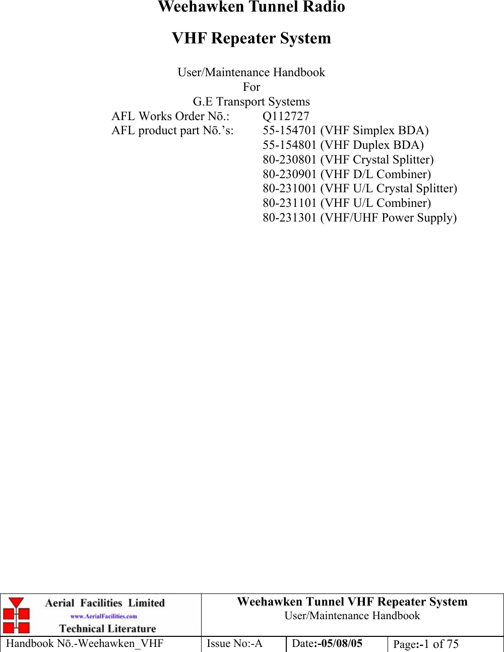
![Weehawken Tunnel VHF Repeater System User/Maintenance Handbook Handbook N.-Weehawken_VHF Issue No:-A Date:-05/08/05 Page:-7 of 75 EC DECLARATION OF CONFORMITY In accordance with BS EN ISO/IEC 17050-1&-2:2004 AERIAL FACILITIES LTD Aerial House Asheridge Road Chesham Bucks HP5 2QD United Kingdom DECLARES, UNDER OUR SOLE RESPONSIBILITY THAT THE FOLLOWING PRODUCT PRODUCT PART NO[S] 55-154701, 55-154801 PRODUCT DESCRIPTION Weehawken VHF amplifier system IN ACCORDANCE WITH THE FOLLOWING DIRECTIVES: 1999/5/EC The Radio & Telecommunications Terminal Equipment Directive Annex V and its amending directives HAS BEEN DESIGNED AND MANUFACTURED TO THE FOLLOWING STANDARD[S] OR OTHER NORMATIVE DOCUMENT[S]: BS EN 60950 Information technology equipment. Safety. General requirements ETS EN 301 489-1 EMC standard for radio equipment and services. Part 1. Common technical requirements I hereby declare that the equipment named above has been designed to comply with the relevant sections of the above referenced specifications. The unit complies with all essential requirements of the Directives. SIGNED B S BARTON TECHNICAL DIRECTOR DATE: 08/11/2005 0086](https://usermanual.wiki/PBE-Europe-as-Axell-Wireless/55-1547VHF/User-Guide-617402-Page-7.png)
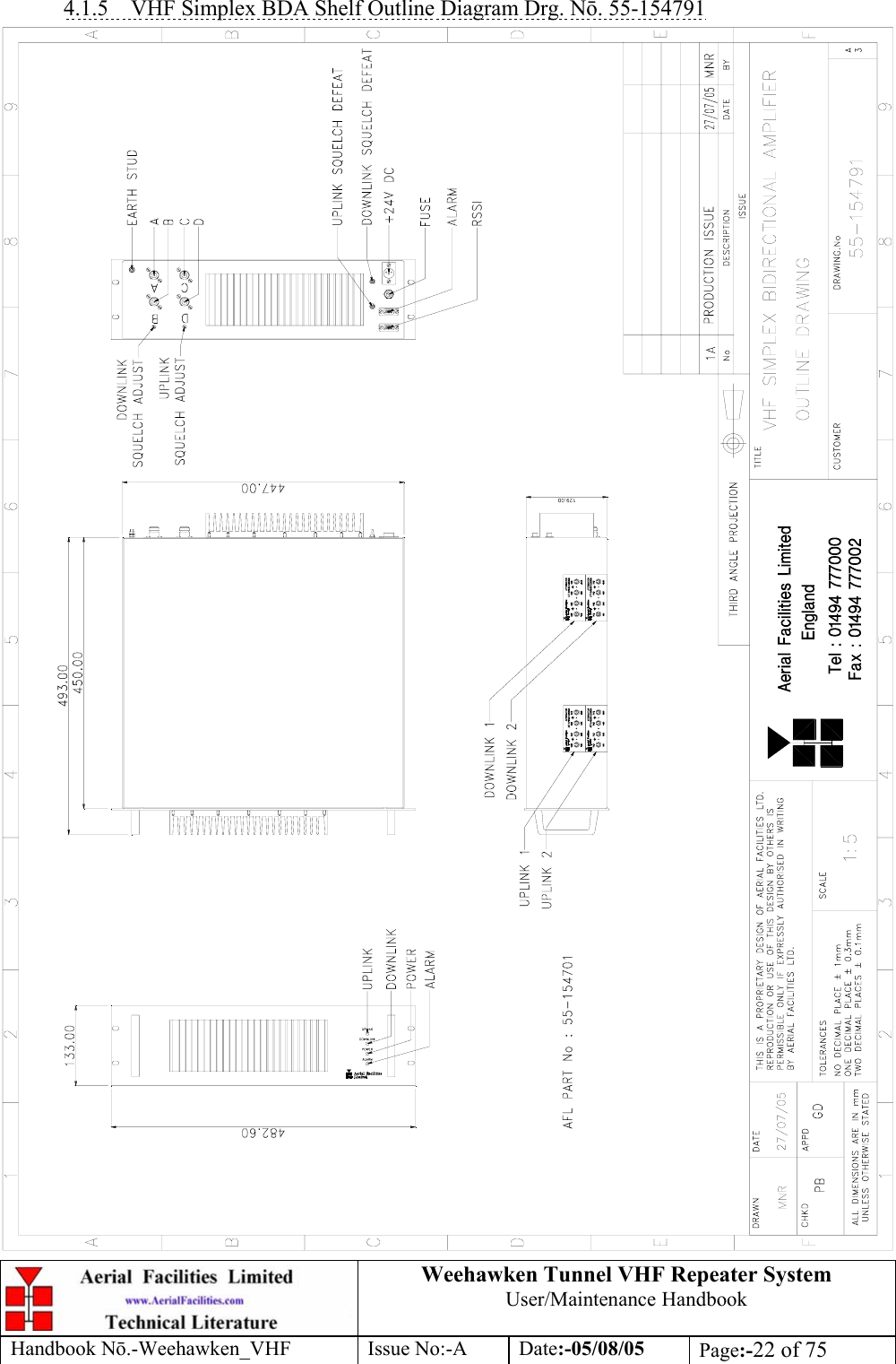
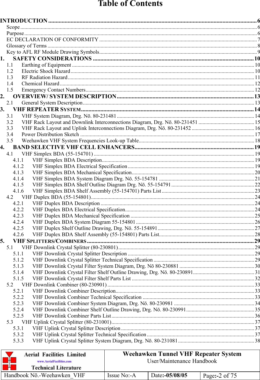
![Weehawken Tunnel VHF Repeater System User/Maintenance Handbook Handbook N.-Weehawken_VHF Issue No:-A Date:-05/08/05 Page:-23 of 75 4.1.6 VHF Simplex BDA Shelf Assembly (55-154701) Parts List AFL Part Nō. Part Description Qty.08-930002 2 PORT ISOLATOR 150-300MHz SMA 2 10-000901 SW. ATTENUATOR 0.25W 0-15dB 4 11-006002 LNA VHF 70-500MHz WITH RELAY 6 12-002213 3 STAGE ALARM/SIMPLEX MUTE PCB SUB-ASS 2 12-002220 3 STAGE ALARM PCB COVER 2 12-002826 ALARM BOARD ACRYLIC LENS 2 12-004902 POWER AMP VHF 5W CLASS AB 2 13-001803 DUAL DC/DC CONVERTER 24V-12V 1A 2 17-009143 VHF 10Kstep CH MOD 15kHz 8p BW+IFRX 2 17-009724 EQUIP. MTG PLATE No.5 2 19-000826 2U,3U,4U 19" UNIT 400 DEEP LID 1 19-000921 3U 19" UNIT 400 DEEP CHASSIS + BKT 1 19-000924 3U 19" UNIT FRONT PANEL FAB 1 20-001602 24V RELAY BOARD 2 80-063920 HEATSINK 2U ASS140 (5W) MILCHBUCK 2 91-030002 N ADAPTOR PANEL FEMALE:FEMALE 4 91-500001 POWER PLG 3 PIN PNL.MOUNT NC-X 1 91-510003 3 PIN R.ANGLE FREE SOC.NC-X. 1 91-600001 'D'TYPE 9 WAY PLUG S/B TERM 1 91-600014 'D' 9 WAY SOCKET S/B (NON FILTERED) 5 91-620001 'D' 25 WAY SOCKET S/B TERM 2 91-700017 ICD 15 WAY 0.1' CONNECTOR 2 93-540035 1K3 0.25W 1% RES MRS25 M:F 2 96-110001 FUSE HOLDER 20 x 5mm6.3A 1 96-600002 INSULATING BOOT SMALL 1 96-600003 INSULATING BOOT D.C. 1 96-700017 LED AMBER 5mm SEALED IP66 2 96-700034 LED RED 5mm IP67 1 96-700035 LED GREEN 5mm IP67 1 97-400005 HANDLE TYPE H6802 3U [ALLOY] 2](https://usermanual.wiki/PBE-Europe-as-Axell-Wireless/55-1547VHF/User-Guide-617402-Page-23.png)
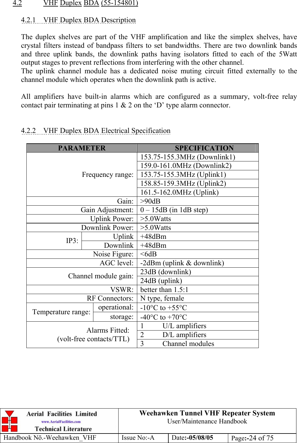
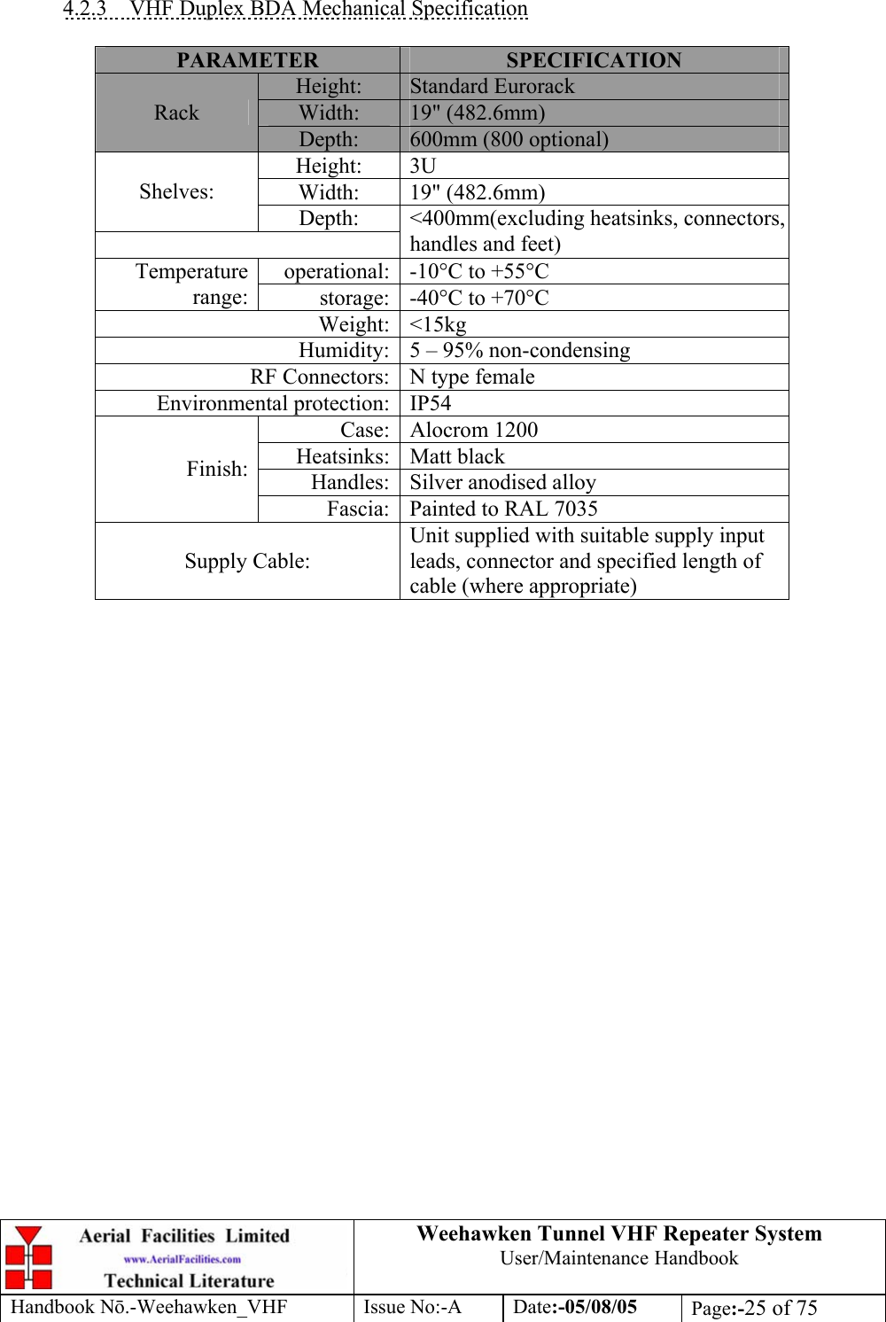
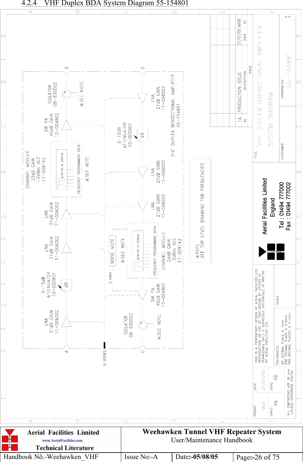
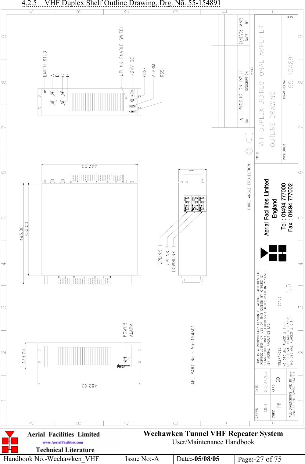
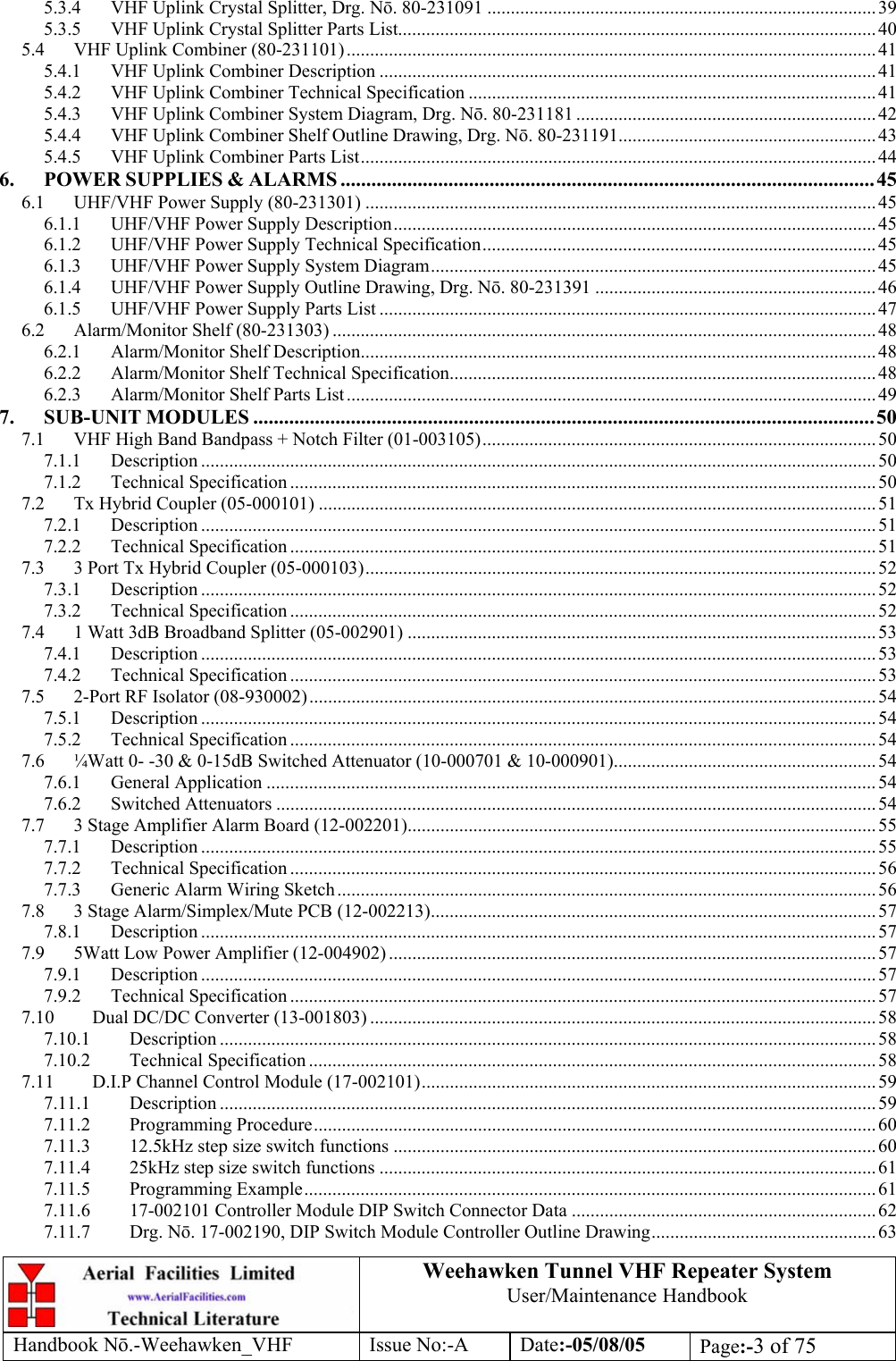
![Weehawken Tunnel VHF Repeater System User/Maintenance Handbook Handbook N.-Weehawken_VHF Issue No:-A Date:-05/08/05 Page:-28 of 75 4.2.6 VHF Duplex BDA Shelf Assembly (55-154801) Parts List AFL Part Nō. Part Description Qty.08-930002 2 PORT ISOLATOR 150-300MHz SMA 2 10-000901 SW. ATTENUATOR 0.25W 0-15dB 4 11-006002 LNA VHF 70-500MHz WITH RELAY 6 12-002201 3 STAGE AMPLIFIER ALARM BOARD 1 12-002213 3 STAGE ALM/SIMPLEXMUTE PCB SUB-ASS 1 12-002220 3 STAGE ALARM PCB COVER 2 12-002826 ALARM BOARD ACRYLIC LENS 2 12-004902 POWER AMP VHF 5W CLASS AB 2 13-001803 DUAL DC/DC CONVERTER 24V-12V 1A 2 17-001105 CE AGC UNIT LOG DET/AMP ASSY (24V) 1 17-001107 OPEN COLLECTOR FOR SIMPLEX CONT. 1 17-009143 VHF 10Kstep CH MOD 15kHz 8p BW+IFRX 2 17-009725 EQUIP. MTG PLATE No.6 2 19-000826 2U,3U,4U 19" UNIT 400 DEEP LID 1 19-000921 3U 19" UNIT 400 DEEP CHASSIS + BKT 1 19-000924 3U 19" UNIT FRONT PANEL FAB 1 20-001601 12V RELAY BOARD 1 80-008902 24V RELAY PCB ASSEMBLY 1 80-063920 HEATSINK 2U ASS140 (5W) MILCHBUCK 2 91-030002 N ADAPTOR PANEL FEMALE:FEMALE 4 91-500001 POWER PLG 3 PIN PNL.MOUNT NC-X 1 91-510003 3 PIN R.ANGLE FREE SOC.NC-X. 1 91-600001 'D'TYPE 9 WAY PLUG S/B TERM 1 91-600007 'D' 9 WAY BLACK SHELL 1 91-600014 'D' 9 WAY SOCKET S/B (NON FILTERED) 7 91-620001 'D' 25 WAY SOCKET S/B TERM 2 91-700017 ICD 15 WAY 0.1' CONNECTOR 3 96-110001 FUSE HOLDER 20 x 5mm6.3A 1 96-600002 INSULATING BOOT SMALL 1 96-600003 INSULATING BOOT D.C. 1 96-700034 LED RED 5mm IP67 1 96-700035 LED GREEN 5mm IP67 1 97-400005 HANDLE TYPE H6802 3U [ALLOY] 2](https://usermanual.wiki/PBE-Europe-as-Axell-Wireless/55-1547VHF/User-Guide-617402-Page-28.png)

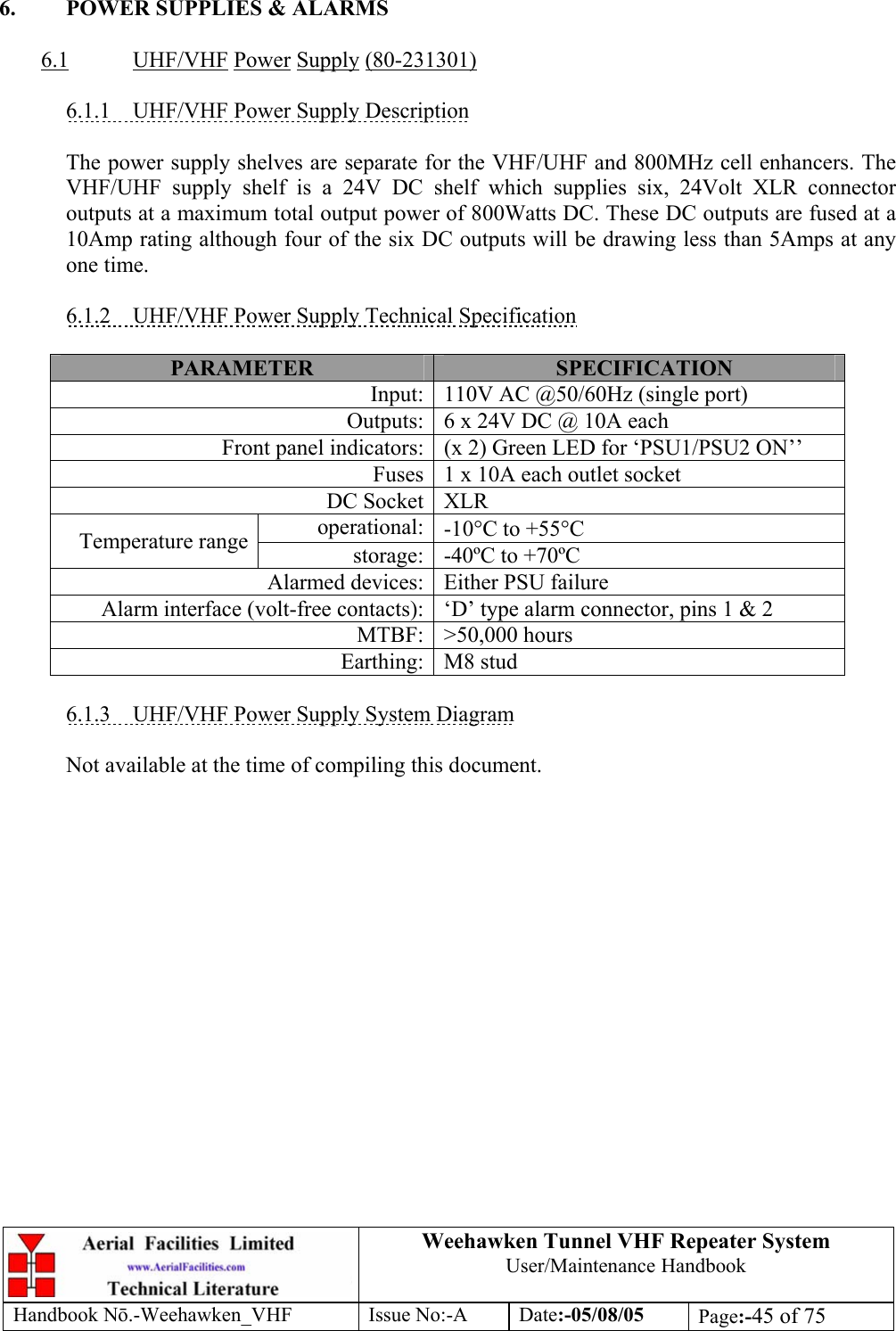
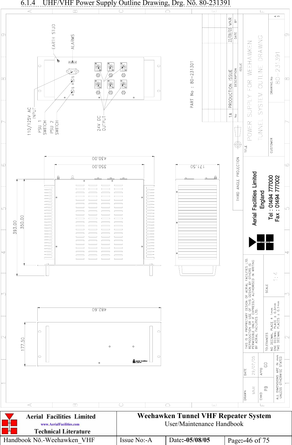
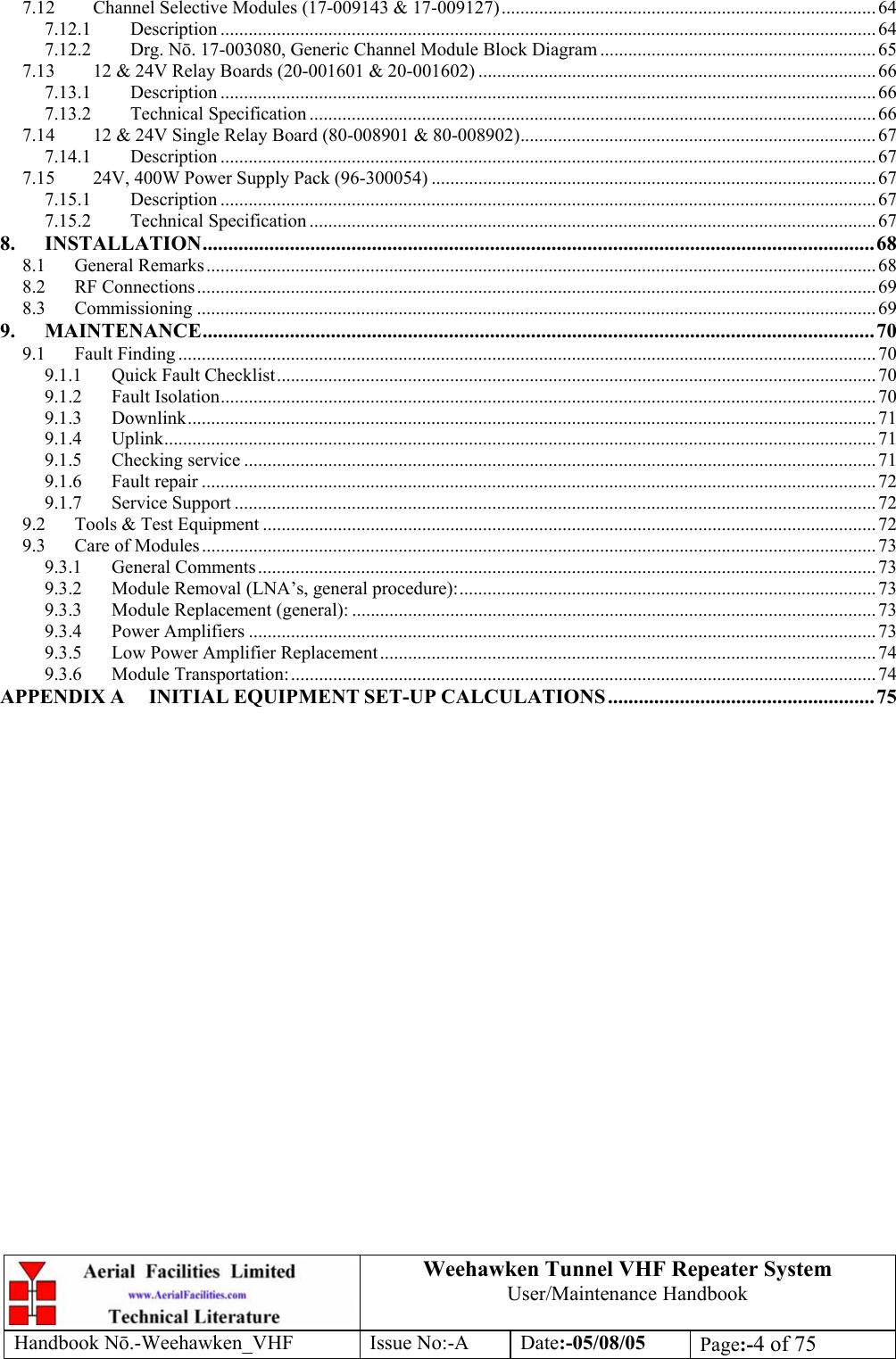
![Weehawken Tunnel VHF Repeater System User/Maintenance Handbook Handbook N.-Weehawken_VHF Issue No:-A Date:-05/08/05 Page:-47 of 75 6.1.5 UHF/VHF Power Supply Parts List AFL Part Nō. Part Description Qty.13-003301 MAINS FILTER 8AMP ASSEMBLY 1 20-001602 24V RELAY BOARD 1 80-008920 DUAL PSU HEATSINK 2 80-008921 DUAL PSU CASE 1 80-008922 DUAL PSU LID 1 80-008925 DUAL PSU FRONT PANEL 1 80-020632 2U CHASSIS LID FIXING RAIL 4 91-500025 3 PIN RIGHT ANGLE FREE PLUG NC-X 6 91-510004 3 PIN PNL.MOUNT SOCKET NC-X 6 91-510035 3 WAY MATE N LOK PLUG HOUSING 2 91-520001 PWR MAINS INL FIXED/SOLD.TERMS 1 91-520005 MAINS LEAD 1 91-520010 MAINS RETAINING CLIP 1 91-520032 MATE N LOK SOCKET CONTACT 20/14 AWG 6 91-600015 'D' 9 WAY PLUG S/B (NON FILTERED) 1 91-800014 3 WAY TERMINAL BLOCK 1 91-800015 TRIPLE DECK TERMINAL BLOCK 8 91-800016 TRIPLE DECK TERMINAL JUMPER 6 91-800017 TRIPLE DECK TERMINAL END 1 91-800028 DIN RAIL END-STOP 2 91-800031 SYMETRIC 35 x 7.5mm DIN RAIL 0 92-900014 DIN RAIL (TOP HAT) EARTH CLAMP M5 1 93-510077 0R02 50W RESISTOR ALUMINIUM CLAD 2 94-100004 STPS12045TV 60A DUAL DIODE 1 95-100007 TX.FERRITE ISOL.HT.SINK B/ANOD 3 96-110034 FUSE HOLDER 16-30A, 32mm BODY ONLY 6 96-110064 FUSE HOLDER 16-30A, 32mm INSERT 6 96-300054 24V 17A PSU 400W (XP BCC) 2 96-600001 INSULATING BOOT LARGE 1 96-700034 LED RED 5mm IP67 1 96-700035 LED GREEN 5mm IP67 2 96-920023 5A CIRCUIT BREAKER (ETA) 2 97-400002 HANDLE TYPE H6803 4U.[ALLOY] 2](https://usermanual.wiki/PBE-Europe-as-Axell-Wireless/55-1547VHF/User-Guide-617402-Page-47.png)