PBE Europe as Axell Wireless 60-1376SERIES Signal Booster type 60-137705 User Manual 60 137705HBKM FCC
Axell Wireless Signal Booster type 60-137705 60 137705HBKM FCC
User manual

Aerial Facilities Limited
Technical Literature
Document layout
Handbook Number: 60-137705HBKM Issue No: A Date: 02/03/2006 Page: 1 of 20
Aerial Facilities Limited
UHF
Bi-Directional Amplifier
AFL product part No: 60-137705
Handbook Title:-BDA
User Handbook
Handbook No. 60-137705HBK Page: 2 of 20
Table of Contents
1. INTRODUCTION ............................................................................................................................... 3
Scope and Purpose of Document ....................................................................................................... 3
Limitation of Liability Notice................................................................................................................. 3
2. SAFETY CONSIDERATIONS ...................................................................................................... 4
2.1 Earthing of Equipment............................................................................................................ 4
2.2 Electric Shock Hazard............................................................................................................ 4
2.3 RF Radiation Hazard.............................................................................................................. 4
2.4 Chemical Hazard.................................................................................................................... 5
2.5 Laser Safety ........................................................................................................................... 5
2.6 Emergency Contact Numbers ................................................................................................ 5
3. EQUIPMENT OVERVIEW............................................................................................................ 6
3.1 Technical Specification (whole system) ................................................................................. 6
3.2 Mechanical Specification........................................................................................................7
3.3 Parts List ................................................................................................................................ 8
3.4 System Drawings ................................................................................................................... 9
3.4.1 BDA Shelf System Diagram ............................................................................................... 9
4. INSTALLATION.......................................................................................................................... 11
4.1 Initial Installation Record ...................................................................................................... 11
5. FAULT FINDING & MAINTENANCE.......................................................................................... 12
5.1 General Fault Finding Procedures ....................................................................................... 12
5.2 Downlink............................................................................................................................... 13
5.3 Uplink ................................................................................................................................... 13
5.4 Fault repair ........................................................................................................................... 13
5.5 Checking service.................................................................................................................. 14
5.6 Service Support.................................................................................................................... 14
5.7 Tools & Test Equipment....................................................................................................... 14
5.8 General Maintenance Procedures........................................................................................ 15
5.9 Module Removal (LNA’s, general procedure): ..................................................................... 15
5.10 Module Replacement (general): ........................................................................................... 15
5.11 Power Amplifiers .................................................................................................................. 15
5.12 Low Power Amplifier Replacement ...................................................................................... 16
5.13 Module Transportation: ........................................................................................................ 16
APPENDIX A ....................................................................................................................................... 17
Amendment List Record Sheet ......................................................................................................... 17
Glossary of Terms............................................................................................................................. 18
Key to Drawing Symbols used in this document ............................................................................... 19
APPENDIX B ....................................................................................................................................... 20
Initial Equipment Set-Up Calculations............................................................................................... 20
General Information........................................................................................................................ 20
Antenna Systems ........................................................................................................................... 20
Initial Parameters ........................................................................................................................... 20
Downlink Calculations .................................................................................................................... 20
Uplink Calculations......................................................................................................................... 20
Handbook Title:-BDA
User Handbook
Handbook No. 60-137705HBK Page: 3 of 20
1. INTRODUCTION
Scope and Purpose of Document
This handbook is for use solely with the equipment identified by the AFL Part Number shown on the
front cover. It is not to be used with any other equipment unless specifically authorised by Aerial
Facilities Limited. This is a controlled release document and, as such, becomes a part of Aerial
Facilities’ Total Quality Management System. Alterations and modification may therefore only be
performed by Aerial Facilities Ltd.
AFL recommends that the installer of this equipment familiarise his/herself with the safety and
installation procedures contained within this document before installation commences.
The purpose of this handbook is to provide the user/maintainer with sufficient information to service
and repair the equipment to the level agreed. Maintenance and adjustments to any deeper level must
be performed by AFL, normally at the company’s repair facility in Chesham, England.
This handbook has been prepared in accordance with BS 4884, and AFL’s Quality procedures, which
maintain the company’s registration to BS EN ISO 9001:2000 and to the R&TTE Directive of the
European Parliament. Copies of the relevant certificates and the company Quality Manual can be
supplied on application to the Quality Manager.
This document fulfils the relevant requirements of Article 6 of the R&TTE Directive.
Limitation of Liability Notice
This manual is written for the use of technically competent operators/service persons. No liability is
accepted by AFL for use or misuse of this manual, the information contained therein, or the
consequences of any actions resulting from the use of the said information, including, but not limited
to, descriptive, procedural, typographical, arithmetical, or listing errors.
Furthermore, AFL does not warrant the absolute accuracy of the information contained within this
manual, or it’s completeness, fitness for purpose, or scope.
AFL has a policy of continuous product development and enhancement, and as such, reserves the
right to amend, alter, update and generally change the contents, appearance and pertinence of this
document without notice.
All AFL products carry a twelve month warranty from date of shipment. The warranty is expressly on a
return to base repair or exchange basis and the warranty cover does not extend to on-site repair or
complete unit exchange.

Handbook Title:-BDA
User Handbook
Handbook No. 60-137705HBK Page: 4 of 20
2. SAFETY CONSIDERATIONS
2.1 Earthing of Equipment
Cell Enhancers supplied from the mains must be connected to grounded outlets and
earthed in conformity with appropriate local, national and international electricity
supply and safety regulations.
2.2 Electric Shock Hazard
Electrical shocks due to faulty mains driven power supplies.
Whilst ever potentially present in any electrical equipment, such a condition would be
minimised by quality installation practice and thorough testing at:
a) Original assembly
b) Commissioning
c) Regular intervals, thereafter.
All test equipment to be in good working order prior to its use. High current power supplies can be
dangerous because of the possibility of substantial arcing. Always switch off during disconnection and
reconnection.
2.3 RF Radiation Hazard
RF radiation, (especially at UHF frequencies) arising from transmitter outputs
connected to AFL’s equipment, must be considered a safety hazard.
This condition might only occur in the event of cable disconnection, or because a
‘spare’ output has been left unterminated. Either of these conditions would impair the
system’s efficiency. No investigation should be carried out until all RF power sources have been
removed. This would always be a wise precaution, despite the severe mismatch between the
impedance of an N type connector at 50, and that of free space at 377, which would severely
mitigate against the efficient radiation of RF power. Radio frequency burns could also be a hazard, if
any RF power carrying components were to be carelessly touched!
Antenna positions should be chosen to comply with requirements (both local & statutory) regarding
exposure of personnel to RF radiation. When connected to an antenna, the unit is capable of
producing RF field strengths, which may exceed guideline safe values especially if used with
antennas having appreciable gain. In this regard the use of directional antennas with backscreens
and a strict site rule that personnel must remain behind the screen while the RF power is on, is
strongly recommended.
Where the equipment is used near power lines, or in association with temporary masts not having
lightning protection, the use of a safety earth connected to the case-earthing bolt is strongly advised.

Handbook Title:-BDA
User Handbook
Handbook No. 60-137705HBK Page: 5 of 20
2.4 Chemical Hazard
Beryllium Oxide, also known as Beryllium Monoxide, or Thermalox™, is sometimes
used in devices within equipment produced by Aerial Facilities Ltd. Beryllium oxide
dust can be toxic if inhaled, leading to chronic respiratory problems. It is harmless if
ingested or by contact.
Products that contain beryllium are load terminations (dummy loads) and some power amplifiers.
These products can be identified by a yellow and black “skull and crossbones” danger symbol (shown
above). They are marked as hazardous in line with international regulations, but pose no threat under
normal circumstances. Only if a component containing beryllium oxide has suffered catastrophic
failure, or exploded, will there be any danger of the formation of dust. Any dust that has been created
will be contained within the equipment module as long as the module remains sealed. For this reason,
any module carrying the yellow and black danger sign should not be opened. If the equipment is
suspected of failure, or is at the end of its life-cycle, it must be returned to Aerial Facilities Ltd for
disposal.
To return such equipment, please contact the Quality Department, who will give you a Returned
Materials Authorisation (RMA) number. Please quote this number on the packing documents, and on
all correspondence relating to the shipment.
PolyTetraFluoroEthylene, (P.T.F.E.) and P.T.F.E. Composite Materials
Many modules/components in AFL equipment contain P.T.F.E. as part of the RF insulation barrier.
This material should never be heated to the point where smoke or fumes are evolved. Any person
feeling drowsy after coming into contact with P.T.F.E. especially dust or fumes should seek medical
attention.
2.5 Laser Safety
General working practices adapted from EN60825-2: 2000
“Do not stare with unprotected eyes or with any unapproved optical device at the fibre
ends or connector faces or point them at other people.”
“Use only approved filtered or attenuating viewing aids.”
“Any single or multiple fibre end or ends found not to be terminated (for example,
matched, spliced) shall be individually or collectively covered when not being worked
on. They shall not be readily visible and sharp ends shall not be exposed.”
“When using test cords, the optical power source shall be the last connected and the first
disconnected.”
“Use only approved methods for cleaning and preparing optical fibres and optical connectors.”
Always keep optical connectors covered to avoid physical damage
Do not allow any dirt/foreign material ingress on the optical connector bulkheads.
The optical fibre jumper cable maximum bend radius is 3cm, any smaller radii may result in optical
cable breakage or excessive transmission losses.
Caution: The FO units are NOT weather proof.
2.6 Emergency Contact Numbers
The AFL Quality Department can be contacted on:
Telephone +44 (0)1494 777000
Fax +44 (0)1494 777002
e-mail qa@aerialfacilities.com

Handbook Title:-BDA
User Handbook
Handbook No. 60-137705HBK Page: 6 of 20
3. EQUIPMENT OVERVIEW
The BDA system comprises two standard 19” rack mounted shelves:-
60-173705 (PSU & RF Amplifiers BDA shelf)
80-245102 (Stand-alone Amplifier shelf)
3.1 Technical Specification (whole system)
PARAMETER SPECIFICATION
Downlink frequency range: 408–411MHz
Uplink frequency range: 417-420MHz
Gain: 60dB
Passband ripple: ±1.5dB
Attenuation: 0-30dB
Downlink OIP3: +65dBm
Uplink OIP3: +40dBm
Base 4 Carriers -10dBm (antenna output)
RF levels (BDA shelf): Mobile: 4 Carriers +37dBm (antenna output)
30A max.@ 24V DC
Power supply consumption: 1.0A max @ 12V DC
Impedance: 50
+37dBm per carrier(D/L)
AGC level: 0dBm (U/L)
Alarms: 4 x LNA, 2 x LPA, & 2 x 100W PA
Summary alarm connector outputs: Pins 1 & 2
operation: -10%C to +60%C
Temperature range: storage: -20%C to +70%C

Handbook Title:-BDA
User Handbook
Handbook No. 60-137705HBK Page: 7 of 20
3.2 Mechanical Specification
PARAMETER SPECIFICATION
Height: 23U Standard Eurorack
Width: 19" (482.6mm)
Racks
Depth: 600mm (800 optional)
8U (BDA shelf)
Height: 4U (amplifier shelf)
Width: 19" (482.6mm)
Shelves:
Depth:
<400mm(excluding heatsinks, connectors,
handles and feet)
operational: -10°C to +55°C Temperature
range: storage: -40°C to +70°C
Weight: <30kg (both shelves)
Humidity: 5 – 95% non-condensing
RF Connectors: N type female & SMA
Environmental Protection: IP44
Supply Cable:
Unit supplied with suitable supply input
leads, connector and specified length of
cable

Handbook Title:-BDA
User Handbook
Handbook No. 60-137705HBK Page: 8 of 20
3.3 Parts List
AFL Part Nō. Part Description Qty.
02-010701 5P C/L(V.B/W)X CPLING SMA 40mm POST 4
10-000701 1/4W0-30dB SWITCHED ATTENUATOR 1
10-000801 1W 0-30dB SWITCHED ATTENUATOR ASS. 1
11-007402K LNA. 380-500MHz 30dB (relay) KIT 1
11-007901K AMPLIFIER TETRA 1W 37dB GAIN KIT 1
12-021801 POWER AMPLIFIER TETRA 1W +12V 1
12-021802 POWER AMPLIFIER TETRA 2W +12V 1
13-003011 DC-DC CONVERTER 24-12V 8A PCB SUB-ASS 1
13-003301 MAINS FILTER 8AMP ASSEMBLY 1
14-000225 CASE RAIL LONG R.S.A./R.F.A. 2
17-001109 CE AGC UNIT LOG DET/AMP ASSY (12v) 1
17-001117 CELL ENHANCER AGC DETECTOR/AMP 12V 1
17-001201 C/E AGC UNIT ATTENUATOR ASSY 2
17-004730 ATTENUATOR MOUNTING 2
17-004733 SIMP.C.E ATTENUATOR COVER(RAL7032) 2
20-001601 12V RELAY BOARD 1
50-012820 CCE RACK MOUNTED 8U CHASSIS 1
50-012822 CCE RACK MOUNTED LID 1
50-012825 CCE RACK MOUNTED HEATSINK BRACKET 4
50-027720 RACK MTD CHAN C.E. MODIFIED HEATSIN 2
80-008901 12V RELAY PCB ASSEMBLY 1
80-090822 C/E 8U FRONT PANEL, AFL (RAL7035) 1
80-310420 BCC 400W POWER SUPPLY HEATSINK 1
90-100011 IEC MAINS LEAD '6 AMP' for USA 1
91-030002 N ADAPTOR PANEL FEMALE:FEMALE 3
91-130001 SMA ADAPT 'T' ALL FEMALE 3 GHz 1
91-130005 SMA BULKHEAD ADAPTOR F/F 2
91-500005 POWER 3 PIN PLG FREE NC-X SER. 3
91-510002 3 PIN STRAIGHT FREE SOC.NC-X. 3
91-510004 3 PIN PNL.MOUNT SOCKET NC-X 3
91-520001 PWR MAINS INL FIXED/SOLD.TERMS 1
91-520010 MAINS RETAINING CLIP 1
91-600001 'D'TYPE 9 WAY PLUG S/B TERM 2
91-600005 'D' 9 WAY SOCKET S/B TERM 2
91-600014 'D' 9 WAY SOCKET S/B (NON FILTERED) 2
91-600015 'D' 9 WAY PLUG S/B (NON FILTERED) 2
91-700017 ICD 15 WAY 0.1' CONNECTOR 1
93-510077 0R02 50W RESISTOR ALUMINIUM CLAD 2
94-100004 STPS12045TV 60A DUAL DIODE 1
96-110001 FUSE HOLDER 20 X 5mm6.3A 1
96-110008 2A FUSE A:SURGE CERAMIC 20x5 1
96-110015 T 15A A/SURGE FUSE 1.25' 2
96-110034 FUSE HOLDER 16-30A, 32mm BODY ONLY 2
96-110064 FUSE HOLDER 16-30A, 32mm INSERT 2
96-300067 24V 23A PSU 600W (XP BCC) 2
96-600001 INSULATING BOOT LARGE 1
96-600002 INSULATING BOOT SMALL 3
96-600003 INSULATING BOOT D.C. 3
96-700034 LED RED 5mm IP67 INTEGRAL RES. 24V 1
96-700035 LED GREEN 5mm IP67 INTEGRAL RES 24V 1
96-920026 CIRCUIT BREAKER 10A 1
97-400005 HANDLE TYPE H6802 3U [ALLOY] 2
Handbook Title:-BDA
User Handbook
Handbook No. 60-137705HBK Page: 9 of 20
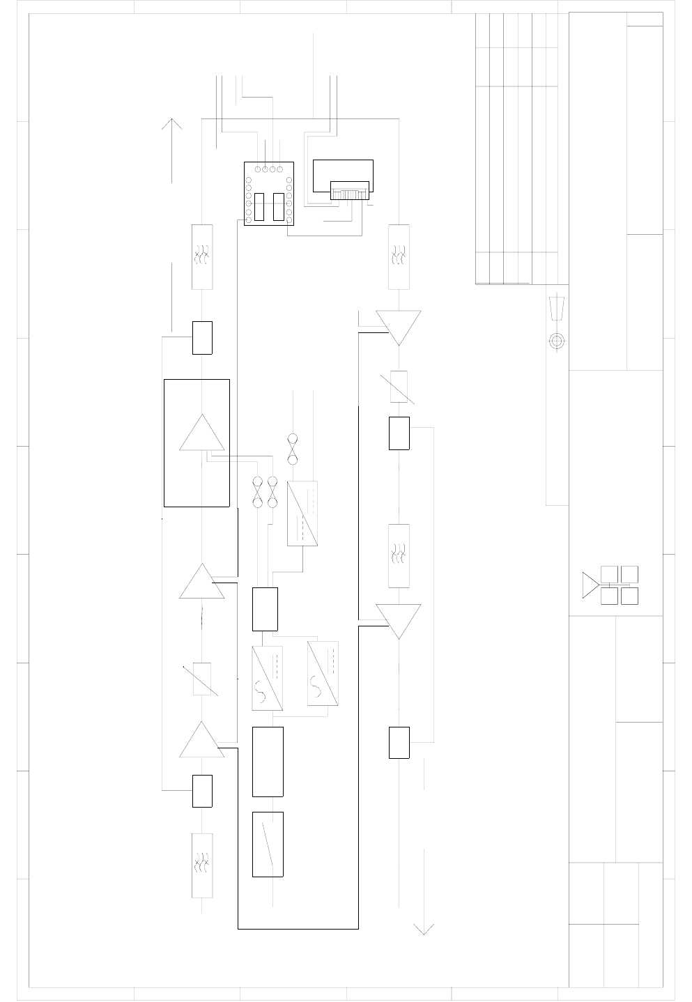
3.4 System Drawings
3.4.2 BDA Shelf System Diagram
Handbook Title:-BDA
User Handbook
Handbook No. 60-137705HBK Page: 10 of 20
UHF FIBRE OPTIC SYSTEM
OVERALL SYSTEM DIAGRAM
60-137783
1A
-
MRB 3/1/06
BYDATEDESCRIPTIONNo
ISSUE
THIRD ANGLE PROJECTION
12
3456789
A
B
C
D
E
F
123456789
A
B
C
D
E
F
Fax : 01494 777002
Tel : 01494 777000
Aerial Facilities Limited
THIS IS A PROPRIETARY DESIGN OF AERIAL FACILITIES LTD.
REP RODUCTION OR USE OF THIS DESIGN BY OTHERS IS
PERMISSIBLE ONLY IF EXPRESSLY AUTHORISED IN WRITING
BY AERIAL FACILITIES LTD.
NO DECIMAL PLACE ± 1mm
ONE DECIMAL PLACE ± 0.3mm
TWO DECIMAL PLACES ± 0.1mm
ALL DIMENSIONS A RE IN mm
UNLESS OTHERWISE STATED
CHKD
DRA WN
APPD
DATE
TOLERANCES SCALE
England
CUS TOM E R DRAWING.No
TITLE
3
A
PRODUCTION ISSUE 3/1/06 MRB
RP GD
15dB 37dB15dB
dB
12-021801 12-021802
37dB 30dB
dB
11-007402
DOWNLINK
UPLINK
17-001109 17-001201
ALC ALC
96-920026 96-300067
24V
MOBILE
10-000801
110V
AC
02-010701 02-010701
80-245102
11-007901
10-000701
AC filter
13-003301
02-010701 02-010701
96-300067
24V
94-100004
96-300067
12V
24V
To LNA/LPA's
17-001201
ALC
17-001117
ALC
To 12V Out
0V
COM N/C N/OCOM N/C N/O
COM N/C N/OCOM N/C N/O
12V
0V
12V
0V
1 2 3 4 5 6 7 8 910 12 14
11 13 15
80-008901
0V
D oor LE D
+12V
12V
12V
0V
0V
1
2
1
2
DB9S
DB9S
1
2
DB9S
RF IN
RF OUT
RF
OUT
RF
IN
RF
OUT
RF
IN
Handbook Title:-BDA
User Handbook
Handbook No. 60-137705HBK Page: 11 of 20
4. INSTALLATION
4.1 Initial Installation Record
When this equipment is initially commissioned, please use the equipment set-up record sheet in
Appendix A. This will help both the installation personnel and AFL should these figures be needed for
future reference or diagnosis.
Handbook Title:-BDA
User Handbook
Handbook No. 60-137705HBK Page: 12 of 20
5. FAULT FINDING & MAINTENANCE
5.1 General Fault Finding Procedures
In the event that the performance of the system is suspect, a methodical and logical approach to the
problem will reveal the cause of the difficulty.
Transmissions from the main base stations are passed though the system to the mobile radio
equipment; this could be a handheld radio or a transceiver in a vehicle. This path is referred to as the
downlink. The return signal path from the mobile radio equipment to the base station is referred to as
the uplink.
The first operation is to check the alarms of each of the active units and determine that the power
supplies to the equipment are connected and active.
This can be achieved remotely (via CEMS, the RS232 Coverage Enhancement Management System,
if fitted), or locally with the front panel LED’s. The green LED on the front panel should be illuminated,
while the red alarm indicator should be off.
If an Alarm is on, then that individual shelf/module must be isolated and individually tested against the
original test specification.
The individual amplifier units within the shelf have a green LED showing through a hole in their piggy-
back alarm board, which is illuminated if the unit is working correctly.
If an amplifier is suspect, check the DC power supply to the unit. If no other fault is apparent use a
spectrum analyser to measure the incoming signal level at the input and then after reconnecting the
amplifier input, measure the output level. Consult with the system diagram to determine the expected
gain and compare result.
In the event that there are no alarms on and all units appear to be functioning it will be necessary to
test the system in a systematic manner to confirm correct operation.
Handbook Title:-BDA
User Handbook
Handbook No. 60-137705HBK Page: 13 of 20
5.2 Downlink
Confirm that there is a signal at the expected frequency and strength from the base station. If this is
not present then the fault may lay outside the system. To confirm this, inject a downlink frequency
signal from a known source at the master site BTS input and check for output at the remote site
feeder output.
If a signal is not received at the output it will be necessary to follow the downlink path through the
system to find a point at which the signal is lost. The expected downlink output for the given input can
be found in the end-to-end test specification.
5.3 Uplink
Testing the uplink involves a similar procedure to the downlink except that the frequencies used are
those transmitted by the mobile equipment.
5.4 Fault repair
Once a faulty component has been identified, a decision must be made on the appropriate course to
carry out a repair. A competent engineer can quickly remedy typical faults such as faulty connections
or cables. The exceptions to this are cable assemblies connecting bandpass filter assemblies that are
manufactured to critical lengths to maintain a 50-ohm system. Care should be taken when replacing
cables or connectors to ensure that items are of the correct specification. The repair of component
modules such as amplifiers and bandpass filters will not usually be possible in the field, as they
frequently require specialist knowledge and test equipment to ensure correct operation. It is
recommended that items of this type are replaced with a spare unit and the faulty unit returned to AFL
for repair.
Handbook Title:-BDA
User Handbook
Handbook No. 60-137705HBK Page: 14 of 20
5.5 Checking service
Following the repair of any part of the system it is recommended that a full end-to-end test is carried
out in accordance with the test specification and that the coverage is checked by survey.
It is important to bear in mind that the system includes a radiating cable network and base stations
that may be faulty or may have been damaged.
5.6 Service Support
Advice and assistance with maintaining and servicing this system are available by contacting Aerial
Facilities Ltd.
5.7 Tools & Test Equipment
The minimum tools and test equipment needed to successfully service this AFL product are as
follows:-
Spectrum analyser: 100kHz to 2GHz (Dynamic range = 90dB).
Signal Generator: 30MHz to 2GHz (-120dBm to 0dBm o/p level).
Attenuator: 20dB, 10W, DC-2GHz, (N male – N female).
Test Antenna: Yagi or dipole for operating frequency.
Digital multi-meter: Universal Volt-Ohm-Amp meter.
Test cable x 2: N male – N male, 2M long RG214.
Test cable x 2: SMA male – N male, 1m long RG223.
Hand tools: Philips #1&2 tip screwdriver.
3mm flat bladed screwdriver.
SMA spanner and torque setter.
Handbook Title:-BDA
User Handbook
Handbook No. 60-137705HBK Page: 15 of 20
5.8 General Maintenance Procedures
Many of the active modules contain semiconductor devices utilising MOS technology, which can be
damaged by electrostatic discharge. Correct handling of such modules is mandatory to ensure their
long-term reliability.
To prevent damage to a module, it must be withdrawn/inserted with care. The module may have
connectors on its underside, which might not be visible to the service operative.
5.9 Module Removal (LNA’s, general procedure):
The following general rules should be followed to remove a module:
1 Remove power to the unit
2 Remove all visible connectors (RF, DC & alarm)
3 Release module retaining screws.
4 Slowly but firmly, pull the module straight out of its position. Take care not to twist/turn the
module during withdrawal. (When the module is loose, care may be needed, as there may be
concealed connections underneath).
5.10 Module Replacement (general):
1 Carefully align the module into its location then slowly push the module directly straight into its
position, taking care not to twist/turn it during insertion.
2 Reconnect all connectors, RF, alarm, power etc.,(concealed connectors may have to be
connected first).
3 Replace retaining screws (if any).
4 Double-check all connections before applying power.
5.11 Power Amplifiers
1) Remove power to the unit. (Switch off @ mains/battery, or remove DC in connector)
2) Remove alarm wires from alarm screw terminal block or disconnect multi-way alarm
connector.
3) Carefully disconnect the RF input and output coaxial connectors (usually SMA)
If alarm board removal is not required, go to step 5.
4) There is (usually) a plate attached to the alarm board which fixes it to the amplifier, remove its
retaining screws and the alarm board can be withdrawn from the amplifier in its entirety. On certain
types of amplifier the alarm board is not mounted on a dedicated mounting plate; in this case it will
have to firstly be removed by unscrewing it from the mounting pillars, in most cases, the pillars will not
have not have to be removed before lifting the amplifier.
5) If the amplifier to be removed has a heatsink attached, there may be several different ways it
can have been assembled. The most commonly used method, is screws through the front of the
heatsink to threaded screw holes (or nuts and bolts), into the amplifier within the main case. If the
heatsink is mounted on the rear of the main case (e.g., against a wall in the case of wall mounted
enclosures), then the fixing method for the heatsink will be from within the case, (otherwise the
enclosure would have to be removed from the wall in order to remove the heatsink).
Handbook Title:-BDA
User Handbook
Handbook No. 60-137705HBK Page: 16 of 20
When the heatsink has been removed, the amplifier may be unscrewed from the main casing by its
four corner fixings and gently withdrawn.
Fitting a new power amplifier module will be the exact reverse of the above.
Note: Do not forget to apply fresh heatsink compound to the heatsink/main case joint and also
between the amplifier and the main case.
5.12 Low Power Amplifier Replacement
Disconnect the mains power supply and disconnect the 24V dc supply connector for the LPA.
Disconnect the RF input and output cables from the LPA.
Disconnect the alarm connector.
Remove the alarm monitoring wires from (D type connector) pins 9 and 10.
Remove the LPA module by removing the four retaining screws, replace with a new LPA module and
secure it with the screws.
Connect the RF cables to the LPA input and output connectors. Reconnect the wires to the alarm
board connector pins 9 and 10.
Reconnect the DC supply connector and turn the mains switch on.
Note: Tighten SMA connectors using only a dedicated SMA torque spanner. If SMA connectors are
over-tightened, irreparable damage will occur. . Do not use adjustable pliers to loosen/tighten SMA
connectors.
Also take care not to drop or knock the module as this can damage (or misalign in the case of tuned
passive modules) sensitive internal components. Always store the modules in an environmentally
friendly location
5.13 Module Transportation:
To maintain the operation, performance and reliability of any module it must be stored and
transported correctly. Any module not installed in a whole system must be kept in an anti-static bag or
container. These bags or containers are normally identified by being pink or black, and are often
marked with an ESD label. Any module sent back to AFL for investigation/repair must be so
protected. Please contact AFL’s quality department before returning a module.
Handbook Title:-BDA
User Handbook
Handbook No. 60-137705HBK Page: 17 of 20
APPENDIX A
Amendment List Record Sheet
Issue No. Date Incorporated
by
Page Nos.
Amended
Reason for
new issue
A 02/03/2006 CMH 1st Draft
Document Ref:-60-137705HBKM

Handbook Title:-BDA
User Handbook
Handbook No. 60-137705HBK Page: 18 of 20
Glossary of Terms
Repeater or
Cell Enhancer
A Radio Frequency (RF) amplifier which can simultaneously
amplify and re-broadcast Mobile Station (MS) and Base
Transceiver Station (BTS) signals.
Band Selective
Repeater
A Cell Enhancer designed for operation on a range of channels
within a specified frequency band.
Channel Selective
Repeater
A Cell Enhancer, designed for operation on specified channel(s)
within a specified frequency band. Channel frequencies may be
factory set or on-site programmable.
AC Alternating Current
AGC Automatic Gain Control
BBU Battery Backup Unit
BTS Base Transceiver Station
CEMS Coverage Enhanced Management System
C/NR Carrier-to-Noise Ratio
DC Direct Current
Downlink (D/L) RF signals Tx from the BTS to the Master Site
FO Fibre Optic
GND Ground
ID Identification Number
LED Light Emitting Diode
LNA Low Noise Amplifier
LPA Low Power Amplifier
MOU Master Optical Unit
M.S. Mobile Station
MTBF Mean Time Between Failures
N/A Not Applicable
N/C No Connection
OFR On Frequency Repeater
OIP3 Output Third Order Intercept Point = RFout +(C/I)/2
PA Power Amplifier
RF Radio Frequency
RSA Receiver/Splitter Amplifier
Rx Receiver
S/N Serial Number
Tx Transmitter
Uplink (U/L) RF signals transmitted from the MS to the BTS
VSWR Voltage Standing Wave Ratio
WDM Wave division multiplex
Handbook Title:-BDA
User Handbook
Handbook No. 60-137705HBK Page: 19 of 20
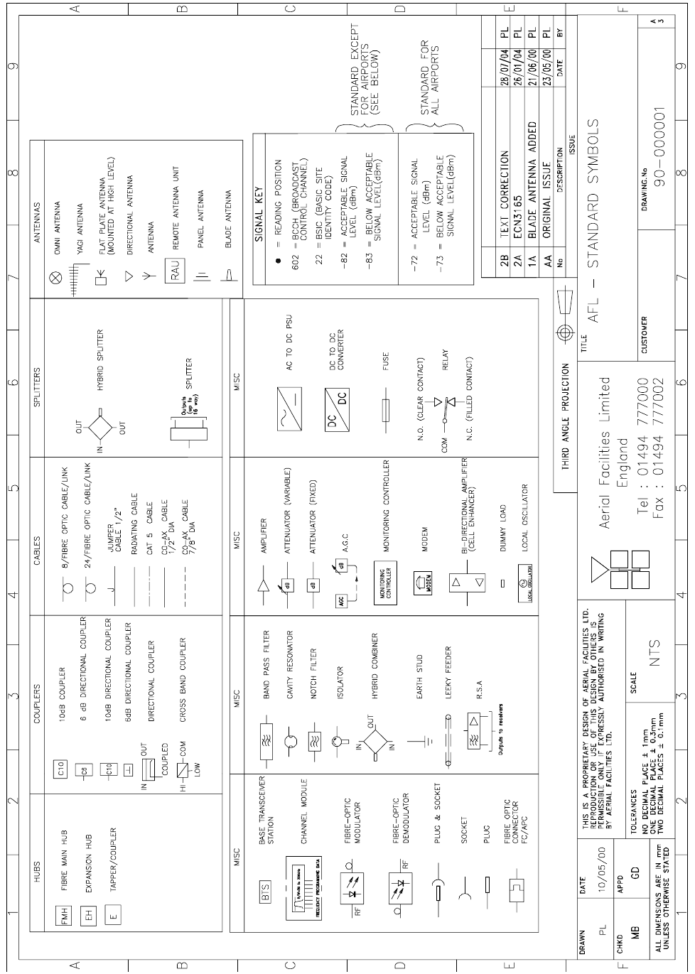
Key to Drawing Symbols used in this document
Handbook Title:-BDA
User Handbook
Handbook No. 60-137705HBK Page: 20 of 20
APPENDIX B
Initial Equipment Set-Up Calculations
General Information
Site Name: Client Name:
Date: AFL Equip. Model No.
Antenna Systems
Model Gain Azimuth Comments
A - Service Antenna
B – Donor Antenna
Type Loss Length Comments
C – Service Feeder
D – Donor Feeder
Initial Parameters
E – CE Output Power dBm
F – Antenna Isolation dB
G – Input signal level from donor BTS dBm
Operating Voltage V
Downlink Calculations
Parameter Comments Value
Input signal level (G) dBm
CE max. o/p power (E) dBm
Gain setting E - G dB
Isolation required (Gain + 10dB) dB
Service antenna gain (A) dB
Service antenna feeder loss (C) dB
Effective radiated power (ERP) E+A-C dBm
Attenuator setting CE gain-gain setting dB
If the input signal level in the uplink path is known and steady, use the following calculation table to
determine the gain setting. If the CE features Automatic Gain Control the attenuator should be set to
zero and if not, then the attenuation setting for both uplink and downlink should be similar.
Uplink Calculations
Parameter Comments Value
Input signal level dBm
CE max. o/p power (E) dBm
Gain setting dB
Required isolation dB
Donor antenna gain (B) dB
Donor antenna feeder loss (D) dB
Effective radiated power (ERP) E+B-D dBm
Attenuator setting (CE gain-gain setting) dB