PBE Europe as Axell Wireless 60-1658SERIES Remote Booster type 60-165801 User Manual RECEIVER MULTICOUPLER
Axell Wireless Remote Booster type 60-165801 RECEIVER MULTICOUPLER
User manual

Meadowlands Fiber Fed BDA Equipment
User Handbook
Handbook Nō.-60-165801HBKM Issue No:-1
Date:-03/01/06 Page:-1 of 25
220MHz Fibre Feed BDA Equipment
User Reference
For
Pinnacle
AFL Works Order Nō.: Q113673
AFL product part Nō.’s: 60-165801 (Fibre Fed 40W BDA)
Meadowlands Fiber Fed BDA Equipment
User Handbook
Handbook Nō.-60-165801HBKM Issue No:-1
Date:-03/01/06 Page:-2 of 25
Table of Contents
INTRODUCTION ............................................................................................................................................4
Scope................................................................................................................................................................................ 4
Purpose............................................................................................................................................................................ 4
Glossary of Terms .......................................................................................................................................................... 5
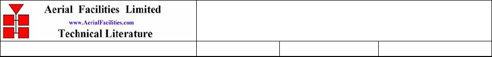
Key to AFL RF Module Drawing Symbols.................................................................................................................. 6
EC DECLARATION OF CONFORMITY.....................................................................................................7
1. SAFETY CONSIDERATIONS ............................................................................................................8
1.1 Earthing of Equipment ..................................................................................................................................... 8
1.2 Electric Shock Hazard ......................................................................................................................................8
1.3 RF Radiation Hazard........................................................................................................................................ 9
1.4 Chemical Hazard............................................................................................................................................. 10
1.5 Laser safety...................................................................................................................................................... 11
1.6 Emergency Contact Numbers ........................................................................................................................ 11
2. OVERVIEW/ SYSTEM DESCRIPTION..........................................................................................12
3. FIBRE-FED BDA (60-165801) .............................................................................................................13
3.1 Component Layout Photograph .................................................................................................................... 13
3.2 FO BDA Electrical Specifications.................................................................................................................. 14
3.3 FO BDA RF Circuit Diagram, Drg. Nō. 60-165881 ..................................................................................... 15
3.4 FO BDA Alarm Circuit Diagram, Drg. Nō. 60-165851................................................................................ 16
3.5 FO BDA Parts List .......................................................................................................................................... 17
5. INSTALLATION.................................................................................................................................18
5.1 General Remarks ............................................................................................................................................ 18
5.2 RF Connections ............................................................................................................................................... 18
5.3 Commissioning ................................................................................................................................................ 19
6. MAINTENANCE.................................................................................................................................20
6.1 Fault Finding ................................................................................................................................................... 20
6.1.1 Quick Fault Checklist....................................................................................................................................20
6.1.2 Fault Isolation...............................................................................................................................................20
6.1.3 Downlink .......................................................................................................................................................21
6.1.4 Uplink............................................................................................................................................................21
6.1.5 Checking service ...........................................................................................................................................21
6.1.6 Fault repair...................................................................................................................................................22
6.1.7 Service Support .............................................................................................................................................22
6.2 Tools & Test Equipment................................................................................................................................. 22
6.3 Care of Modules .............................................................................................................................................. 23
6.3.1 General Comments........................................................................................................................................23
6.3.2 Module Removal (LNA’s, general procedure):.............................................................................................23
6.3.3 Module Replacement (general):....................................................................................................................23
6.3.4 Power Amplifiers...........................................................................................................................................23
6.3.5 Low Power Amplifier Replacement...............................................................................................................24
6.3.6 Module Transportation:................................................................................................................................24
APPENDIX A INITIAL EQUIPMENT SET-UP CALCULATIONS ....................................................25

Meadowlands Fiber Fed BDA Equipment
User Handbook
Handbook Nō.-60-165801HBKM Issue No:-1
Date:-03/01/06 Page:-3 of 25
AMENDMENT LIST RECORD SHEET
Issue
Nō.
Date Incorporated
by
Page No.’s
Amended
Reason for new issue
A 19/12/05 G Dawson Draft
AA 03/01/06 CMH 2nd Draft
1 03/01/2006 CMH 1st Issue
2 04/01/2006 CMH Missing CE
conformity
numbers
2nd Issue
Document Ref:-60-165801HBKM

Meadowlands Fiber Fed BDA Equipment
User Handbook
Handbook Nō.-60-165801HBKM Issue No:-1
Date:-03/01/06 Page:-4 of 25
INTRODUCTION
Scope
This handbook is for use solely with the equipment identified by the AFL Part Number shown
on the front cover. It is not to be used with any other equipment unless specifically authorised
by Aerial Facilities Limited.
Purpose
The purpose of this handbook is to provide the user/maintainer with sufficient information to
service and repair the equipment to the level agreed. Maintenance and adjustments to any
deeper level must be performed by AFL, normally at the company’s repair facility in Chesham,
England.
This handbook has been prepared in accordance with BS 4884, and AFL’s Quality procedures,
which maintain the company’s registration to BS EN ISO 9001:2000 and to the R&TTE
Directive of the European Parliament. Copies of the relevant certificates and the company
Quality Manual can be supplied on application to the Quality Manager.
This document fulfils the relevant requirements of Article 6 of the R&TTE Directive.
Limitation of Information Notice
This manual is written for the use of technically competent operators/service persons. No
liability is accepted by AFL for use or misuse of this manual, the information contained
therein, or the consequences of any actions resulting from the use of the said information,
including, but not limited to, descriptive, procedural, typographical, arithmetical, or listing
errors.
Furthermore, AFL does not warrant the absolute accuracy of the information contained within
this manual, or its completeness, fitness for purpose, or scope.
AFL has a policy of continuous product development and enhancement, and as such, reserves
the right to amend, alter, update and generally change the contents, appearance and pertinence
of this document without notice.
All AFL products carry a twelve month warranty from date of shipment. The warranty is
expressly on a return to base repair or exchange basis and the warranty cover does not extend
to on-site repair or complete unit exchange.

Meadowlands Fiber Fed BDA Equipment
User Handbook
Handbook Nō.-60-165801HBKM Issue No:-1
Date:-03/01/06 Page:-5 of 25
Glossary of Terms
Repeater or
Cell Enhancer A Radio Frequency (RF) amplifier which can simultaneously amplify
and re-broadcast Mobile Station (MS) and Base Transceiver Station
(BTS) signals.
Band Selective Repeater A Cell Enhancer designed for operation on a range of channels within
a specified frequency band.
Channel Selective
Repeater A Cell Enhancer, designed for operation on specified channel(s)
within a specified frequency band. Channel frequencies may be
factory set or on-site programmable.
AC Alternating Current
AGC Automatic Gain Control
BDA Bi-Directional Amplifier
BTS Base Transceiver Station
C/NR Carrier-to-Noise Ratio
DC Direct Current
Downlink (D/L) RF signals Tx from the BTS to the Master Site
FO Fibre Optic
GND Ground
ID Identification Number
LED Light Emitting Diode
LNA Low Noise Amplifier
LPA Low Power Amplifier
MOU Master Optical Unit
M.S. Mobile Station
MTBF Mean Time Between Failures
N/A Not Applicable
N/C No Connection
OIP3 Output Third Order Intercept Point = RFout +(C/I)/2
PA Power Amplifier
RF Radio Frequency
RSA Receiver/Splitter Amplifier
Rx Receiver
S/N Serial Number
Tx Transmitter
Uplink (U/L) RF signals transmitted from the MS to the BTS
VSWR Voltage Standing Wave Ratio
WDM Wave division multiplex
Key
Meadowlands Fiber Fed BDA Equipment
User Handbook
Handbook Nō.-60-165801HBKM Issue No:-1
Date:-03/01/06 Page:-6 of 25
to AFL RF Module Drawing Symbols
EC DECLARATION OF CONFORMITY
In accordance with BS EN ISO/IEC 17050-1&-2:2004
Meadowlands Fiber Fed BDA Equipment
User Handbook
Handbook Nō.-60-165801HBKM Issue No:-1
Date:-03/01/06 Page:-7 of 25
0086
AERIAL FACILITIES LTD
Aerial House
Asheridge Road
Chesham
Bucks HP5 2QD
United Kingdom
DECLARES, UNDER OUR SOLE RESPONSIBILITY THAT THE FOLLOWING PRODUCT
PRODUCT PART NO[S] 60-165801
PRODUCT DESCRIPTION Fibre fed BDA
IN ACCORDANCE WITH THE FOLLOWING DIRECTIVES:
1999/5/EC The Radio & Telecommunications Terminal Equipment Directive Annex V and its amending
directives
HAS BEEN DESIGNED AND MANUFACTURED TO THE FOLLOWING STANDARD[S] OR OTHER
NORMATIVE DOCUMENT[S]:
BS EN 60950 Information technology equipment. Safety. General requirements
ETS EN 301 489-1 EMC standard for radio equipment and services. Part 1. Common technical
requirements
I hereby declare that the equipment named above has been designed to comply with the relevant sections of the above
referenced specifications. The unit complies with all essential requirements of the Directives.
SIGNED
B S BARTON
TECHNICAL DIRECTOR DATE: 20/12/2005
1. SAFETY CONSIDERATIONS
1.1
Meadowlands Fiber Fed BDA Equipment
User Handbook
Handbook Nō.-60-165801HBKM Issue No:-1
Date:-03/01/06 Page:-8 of 25
Earthing of Equipment
Cell Enhancers supplied from the mains must be connected to grounded outlets and earthed in
conformity with appropriate local, national and international electricity supply and safety
regulations.
AFL recommends that all other hardware enclosures and electrically conductive metalwork
within operator reach of the cell enhancer cabinet (enclosing the PSUs) be grounded to the
same earth to prevent hazardous differential voltages between equipment which could result in
electrocution.
This arrangement of grounding and safety earthing has always been implemented by AFL and
meets good RF-engineering grounding practice, thus preventing any risk of electrocution when
touching both the modules and cabinet or due to the leakage from the PSU input filter. The use
of a common ground for the cabinet and AC supply input will have no detrimental affect on the
overall electrical or EMC performance of the equipment.
1.2 Electric Shock Hazard
Electrical shocks due to faulty mains driven power supplies.
Whilst ever potentially present in any electrical equipment, such a condition would be
minimised by quality installation practice and thorough testing at:
a) Original assembly
b) Commissioning
c) Regular intervals, thereafter.
All test equipment to be in good working order prior to its use. High current power supplies can
be dangerous because of the possibility of substantial arcing. Always switch off during
disconnection and reconnection.

1.3
Meadowlands Fiber Fed BDA Equipment
User Handbook
Handbook Nō.-60-165801HBKM Issue No:-1
Date:-03/01/06 Page:-9 of 25
RF Radiation Hazard
RF radiation, (especially at UHF frequencies) arising from transmitter outputs connected to
AFL’s equipment, must be considered a safety hazard.
This condition might only occur in the event of cable disconnection, or because a ‘spare’ output
has been left unterminated. Either of these conditions would impair the system’s efficiency. No
investigation should be carried out until all RF power sources have been removed. This would
always be a wise precaution, despite the severe mismatch between the impedance of an N type
connector at 50Ω, and that of free space at 377Ω, which would severely mitigate against the
efficient radiation of RF power. Radio frequency burns could also be a hazard, if any RF power
carrying components were to be carelessly touched!
Antenna positions should be chosen to comply with requirements (both local & statutory)
regarding exposure of personnel to RF radiation. When connected to an antenna, the unit is
capable of producing RF field strengths, which may exceed guideline safe values especially if
used with antennas having appreciable gain. In this regard the use of directional antennas with
backscreens and a strict site rule that personnel must remain behind the screen while the RF
power is on, is strongly recommended.
Where the equipment is used near power lines or in association with temporary masts not
having lightning protection, the use of a safety earth connected to the case-earthing bolt is
strongly advised.
1.4
Meadowlands Fiber Fed BDA Equipment
User Handbook
Handbook Nō.-60-165801HBKM Issue No:-1
Date:-03/01/06 Page:-10 of 25
Chemical Hazard
Beryllium Oxide, also known as Beryllium Monoxide, or Thermalox™, is sometimes used in
devices within equipment produced by Aerial Facilities Ltd. Beryllium oxide dust can be toxic if
inhaled, leading to chronic respiratory problems. It is harmless if ingested or by contact.
Products that contain beryllium are load terminations (dummy loads) and some power
amplifiers. These products can be identified by a yellow and black “skull and crossbones”
danger symbol (shown above). They are marked as hazardous in line with international
regulations, but pose no threat under normal circumstances. Only if a component containing
beryllium oxide has suffered catastrophic failure, or exploded, will there be any danger of the
formation of dust. Any dust that has been created will be contained within the equipment
module as long as the module remains sealed. For this reason, any module carrying the yellow
and black danger sign should not be opened. If the equipment is suspected of failure, or is at the
end of its life-cycle, it must be returned to Aerial Facilities Ltd for disposal.
To return such equipment, please contact the Quality Department, who will give you a Returned
Materials Authorisation (RMA) number. Please quote this number on the packing documents,
and on all correspondence relating to the shipment.
PolyTetraFluoroEthylene, (P.T.F.E.) and P.T.F.E. Composite Materials
Many modules/components in AFL equipment contain P.T.F.E. as part of the RF insulation
barrier.
This material should never be heated to the point where smoke or fumes are evolved. Any
person feeling drowsy after coming into contact with P.T.F.E. especially dust or fumes should
seek medical attention.
1.5
Meadowlands Fiber Fed BDA Equipment
User Handbook
Handbook Nō.-60-165801HBKM Issue No:-1
Date:-03/01/06 Page:-11 of 25
Laser safety
General working practices adapted from EN60825-2: 2000
“Do not stare with unprotected eyes or with any unapproved optical device at the fibre ends or
connector faces or point them at other people.”
“Use only approved filtered or attenuating viewing aids.”
“Any single or multiple fibre end or ends found not to be terminated (for example, matched,
spliced) shall be individually or collectively covered when not being worked on. They shall not
be readily visible and sharp ends shall not be exposed.”
“When using test cords, the optical power source shall be the last connected and the first
disconnected.”
“Use only approved methods for cleaning and preparing optical fibres and optical connectors.”
Always keep optical connectors covered to avoid physical damage
Do not allow any dirt/foreign material ingress on the optical connector bulkheads.
The optical fibre jumper cable maximum bend radius is 3cm, any smaller radii may result in
optical cable breakage or excessive transmission losses.
Caution: The FO units are NOT weather proof.
1.6 Emergency Contact Numbers
The AFL Quality Department can be contacted on:
Telephone +44 (0)1494 777000
Fax +44 (0)1494 777002
e-mail qa@aerial.co.uk

Meadowlands Fiber Fed BDA Equipment
User Handbook
Handbook Nō.-60-165801HBKM Issue No:-1
Date:-03/01/06 Page:-12 of 25
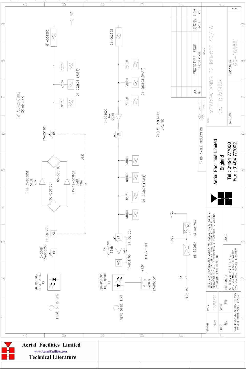
2. OVERVIEW/ SYSTEM DESCRIPTION
The system consists of a fibre optic transmitter and receiver that are co located with the
existing BTS in order to convert the RF signals to optical, which can then be fed to the
optical BDA remotes.
The optical fibre remote BDA’s comprise of a high selectivity filter and duplexing system
built into an environmentally protected enclosure to enable the high power downlink and
low power uplink signals to co-exist on a common antenna port. The D/L signals from the
fibre are fed via an adjustable attenuator and a pair of High Power 20Watt amplifiers
coupled to provide 40Watts downlink power output. In the U/L direction, the low level
signals are passed via the receive duplexer and low noise LNA, before gain adjustment to set
the uplink sensitivity. The signals then pass through a further bank of filters to reduce any
residual Tx carrier power before further amplification to drive the uplink fibre transmitter.
The final uplink amplifier has an ALC loop to ensure that the fibre module cannot be
damaged by large local signals coupled into the antenna system.
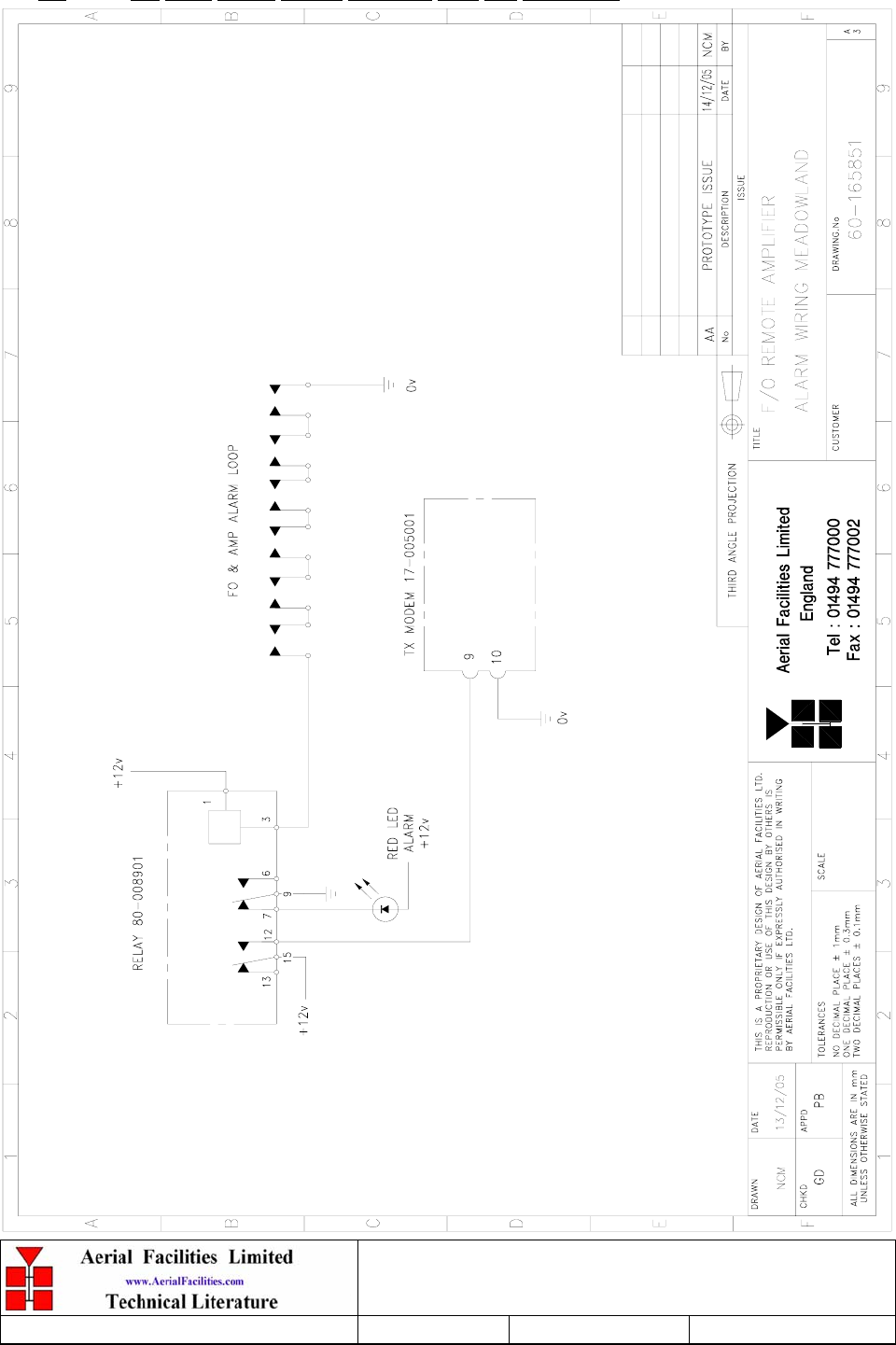
All active components in the remote BDA’s have alarm monitoring with local indicators, an
external panel indicator is fitted to the enclosure. The alarm loop is fed to a 21.4MHz pilot
signal generator which is fed over the fibre back to the FO Mastersite.
3. FIBRE-FED BDA (60-165801)
3.1
Meadowlands Fiber Fed BDA Equipment
User Handbook
Handbook Nō.-60-165801HBKM Issue No:-1
Date:-03/01/06 Page:-13 of 25
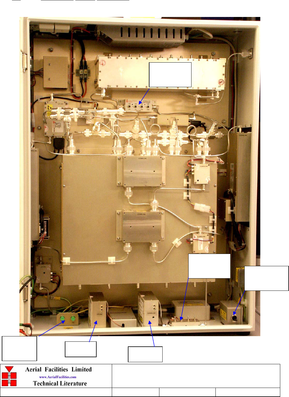
Component Layout Photograph
Uplink
Attenuator
Downlink
Attenuator AC Circuit
Breaker
Fibre
Interface FO Tx FO Rx
Meadowlands Fiber Fed BDA Equipment
User Handbook
Handbook Nō.-60-165801HBKM Issue No:-1
Date:-03/01/06 Page:-14 of 25
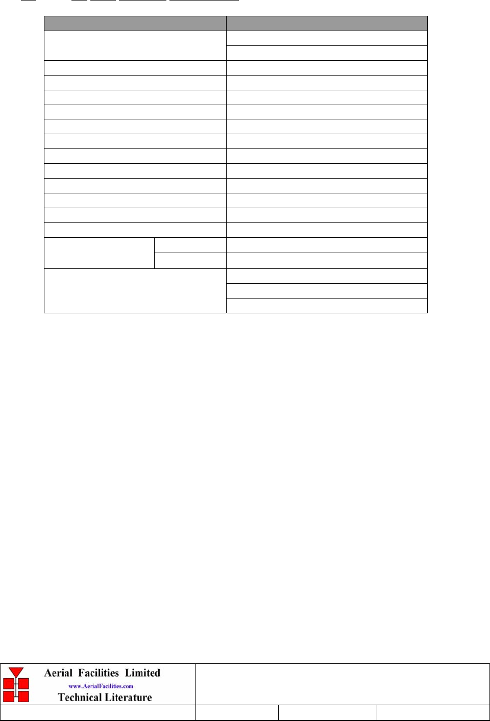
3.2 FO BDA Electrical Specifications
PARAMETER SPECIFICATION
217.5-218.0MHz (Tx)
Frequency range: 219.5-220.0MHz (Rx)
Bandwidth: 0.5MHz
Gain: 0dB
Uplink Gain Adjustment: 0 - 30dB (in 2dB steps)
Downlink gain adjustment: 0-15dB (in 1dB steps)
Uplink Power: 1W
Downlink Power: 40W (20W x2)
IP3: Uplink 47dBm
IP3: Downlink 54dBm
Noise Figure: <6dB
VSWR: better than 1.3:1
RF Connectors: N type, female
F/O Connectors: FC/APC
operational: -10°C to +55°C
Temperature range:
storage: -40°C to +70°C
1 PSU
2 FO Modules
Alarms Fitted:
(volt-free contacts/TTL) 3 Amplifiers
3.3
Meadowlands Fiber Fed BDA Equipment
User Handbook
Handbook Nō.-60-165801HBKM Issue No:-1
Date:-03/01/06 Page:-15 of 25
FO BDA RF Circuit Diagram, Drg. Nō. 60-165881
3.4
Meadowlands Fiber Fed BDA Equipment
User Handbook
Handbook Nō.-60-165801HBKM Issue No:-1
Date:-03/01/06 Page:-16 of 25
FO BDA Alarm Circuit Diagram, Drg. Nō. 60-165851
Meadowlands Fiber Fed BDA Equipment
User Handbook
Handbook Nō.-60-165801HBKM Issue No:-1
Date:-03/01/06 Page:-17 of 25
3.5 FO BDA Parts List
AFL Part Nō. Part Description Qty.
01-002503 FILTER VHF H/B 6SMAS100W 2
01-003603 5 SEC.NOT.FIL.210-225MHz GA 2
05-000103 TX HYBRID COUPLER 3 PORT NO HTSINK 2
10-000703 1/4W0-30dB SWITCHED ATTENUATOR 2
11-006002 LNA VHF 70-500MHz WITH RELAY 1
12-002201 3 STAGE AMPLIFIER ALARM BOARD 2
12-002220 3 STAGE ALARM PCB COVER 2
12-002826 ALARM BOARD ACRYLIC LENS 2
12-003601 POWER AMP.150MHz 20W ASSEMBLY 2
12-023201 AMP. 60-250MHz 1W 35dB GAIN +12V 1
13-001803 DUAL DCDC CONVTR 24V-12V 1A 1
13-001822 DC-DC CON 24V-5V/15V COVER 1
17-001105 CE AGC UNIT LOG DET/AMP ASSY (24v) 1
17-001117 CELL ENHANCER AGC DETECTOR/AMP 12V 1
17-001201 C/E AGC UNIT ATTENUATOR ASSY 2
17-001528 GASKET 20W HEATSINK/BLANKING PLATE 3
17-005001 FIBRE OPTIC ALARM TX PCB (21.4MHz) 1
17-005020 F/O ALARM Tx/Rx PCB COVER WITH SLOT 1
17-009021K ENCLOSURE 820x620x250 (3 x HTS) KIT 1
20-004001 FIBRE OPTIC RF TRANSMITTER (1310nm) 1
20-004103 FIBRE OPTIC RF Rx HIGH GAIN 0-1GHz 1
80-008902 24V RELAY PCB ASSEMBLY 1
80-031820 20W PA HEATSINK (NEEDS 17-001528) 2
80-310420 BCC 400W POWER SUPPLY HEATSINK 1
90-100010 MAINS LEAD '6 AMP' for USA 1
91-030002 N ADAPTOR PANEL FEMALE:FEMALE 1
91-130001 SMA ADAPT 'T' ALL FEMALE 3 GHZ 11
91-500011 PWR 3POLE PNL PLUG SEALED IP68 1
91-500015 PWR CON CAP SEALED with INT. THREAD 1
91-510035 3 WAY MATE N LOK PLUG HOUSING 1
91-520032 MATE N LOK SOCKET CONTACT 20/14 AWG 3
91-600014 'D' 9 WAY SOCKET S/B (NON FILTERED) 4
91-700017 ICD 15 WAY 0.1' CONNECTOR 4
92-120009 M20 IP68 CABLE GLAND 1
92-400017 GASKET FOR N TYPE CONNECTOR 1
96-300054 24V 17A PSU 400W (XP BCC) 1
96-500005 DC INPUT FILTERS 2
96-700034 LED RED 5mm IP67 INTEGRAL RES. 24V 1
96-700035 LED GREEN 5mm IP67 INTEGRAL RES 24V 1
96-900018 AC TRIP SWITCH (5 AMP M.C.B.) 1
97-300010 C/E SUPPLY INPUT COVER 1
97-900004 RUBBER FOOT FOR CELL ENHANCERS 4
98-000001 FC/APC D-HOLE ADAPTOR ADA0004 2
98-500004 FC/APC-FC/APC FIBREOPTIC CABLE 0.5M 2

Meadowlands Fiber Fed BDA Equipment
User Handbook
Handbook Nō.-60-165801HBKM Issue No:-1
Date:-03/01/06 Page:-18 of 25
4. INSTALLATION
When this equipment is initially commissioned, please use the equipment set-up record sheet in
Appendix A. This will help both the installation personnel and AFL should these figures be
needed for future reference or diagnosis.
4.1 General Remarks
The size and weight of the equipment racks mean that they represent a significant topple hazard
unless they are bolted to the floor though the mounting holes in the base of the unit. In the
interests of safety this should be done before any electrical, RF, or optical connections are
made.
The equipment must be located on a flat, level surface that is made from a material suitable for
bearing the weight of the rack assembly. If the installer is in any doubt about the suitability of a
site it is recommended that he consult with an appropriately qualified Structural Engineer.
It is important in determining the location of the rack within the room that space is allowed for
access to the front and rear of the equipment. To enable maintenance to be carried out, the
doors must be able to fully open.
The location must be served with a duct to allow the entry of cables into the rack.
The mains power supply is connected to the terminal strip located on the bulkhead at the rear of
the equipment at floor level. It is recommended that the connection is made by a qualified
electrician, who must satisfy himself that the supply will be the correct voltage and of sufficient
capacity.
All electrical and RF connection should be completed and checked prior to power being
applied for the first time.
4.2 RF Connections
All RF connections are made to the cable termination, located on the bulkhead at the rear of the
equipment at floor level. Care must be taken to ensure that the correct connections are made
with particular attention made to the base station TX/RX ports. In the event that the base
transmitter is connected to the RX output of the rack, damage to the equipment will be done if
the base station transmitter is then keyed.
Ensure that connections are kept clean and are fully tightened.

Meadowlands Fiber Fed BDA Equipment
User Handbook
Handbook Nō.-60-165801HBKM Issue No:-1
Date:-03/01/06 Page:-19 of 25
4.3 Commissioning
Once all connections are made the equipment is ready for commissioning.
To commission the system the test equipment detailed in Section 6.2 will be required.
Using the system diagrams and the end-to-end test specification, the equipment should be
tested to ensure correct operation. Typical RF levels that are not listed in the end-to-end
specification, such as input levels to the fibre transmitters are detailed in the maintenance
section of this manual.
On initial power up the system alarm indicators on the front panels of the equipment should be
checked. A red LED illuminated indicates a fault in that particular tray that must be
investigated before proceeding with the commissioning. A green LED on each shelf
illuminates, to indicate that the power supply is connected to the shelf
In the event that any part of the system does not function correctly as expected, check all
connections to ensure that they are to the correct port, that the interconnecting cables are not
faulty and that they are tightened. The majority of commissioning difficulties arise from
problems with the interconnecting cables and connectors.

Meadowlands Fiber Fed BDA Equipment
User Handbook
Handbook Nō.-60-165801HBKM Issue No:-1
Date:-03/01/06 Page:-20 of 25
5. MAINTENANCE
5.1 Fault Finding
5.1.1 Quick Fault Checklist
All AFLequipment is individually tested to specification prior to despatch. Failure of this type
of equipment is not common. Experience has shown that a large number of fault conditions
relating to tunnel installations result from simple causes often occurring as result of
transportation, unpacking and installation. Below are listed some common problems which have
resulted in poor performance or an indicated non-functioning of the equipment.
• Mains power not connected or not switched on.
• External connectors not fitted or incorrectly fitted.
• Internal connectors becoming loose due to transport vibration.
• Wiring becoming detached as a result of heavy handling.
• Input signals not present due to faults in the aerial and feeder system.
• Base transmissions not present due to fault at the base station.
• Modems fitted with incorrect software configuration.
• Changes to channel frequencies and inhibiting channels.
• Hand held radio equipment not set to repeater channels.
• Hand held radio equipment not set to correct base station.
5.1.2 Fault Isolation
In the event that the performance of the system is suspect, a methodical and logical approach to
the problem will reveal the cause of the difficulty. The System consists of modules fitted in a
wall-mounted, environmentally protected enclosure.
Transmissions from the main base stations are passed though the system to the mobile radio
equipment; this could be a handheld radio or a transceiver in a vehicle. This path is referred to
as the downlink. The return signal path from the mobile radio equipment to the base station is
referred to as the uplink.
The first operation is to check the alarms of each of the active units and determine that the
power supplies to the equipment are connected and active.
This can be achieved locally with the front panel LED’s. The green LED on the front panel
should be illuminated, while the red alarm indicator should be off. If an Alarm is on, then that
individual module must be isolated and individually tested against the original test
specification.
The individual amplifier units within the shelf have a green LED showing through a hole in
their piggy-back alarm board, which is illuminated if the unit is working correctly. If an
amplifier is suspect, check the DC power supply to the unit. If no other fault is apparent use a
spectrum analyser to measure the incoming signal level at the input and then after reconnecting
the amplifier input, measure the output level. Consult with the system diagram to determine the
expected gain and compare result.
In the event that there are no alarms on and all units appear to be functioning it will be
necessary to test the system in a systematic manner to confirm correct operation.

Meadowlands Fiber Fed BDA Equipment
User Handbook
Handbook Nō.-60-165801HBKM Issue No:-1
Date:-03/01/06 Page:-21 of 25
5.1.3 Downlink
Confirm that there is a signal at the expected frequency and strength from the base station. If
this is not present then the fault may lay outside the system. To confirm this, inject a downlink
frequency signal from a known source at the master site BTS input and check for output at the
remote site feeder output.
If a signal is not received at the output it will be necessary to follow the downlink path through
the system to find a point at which the signal is lost. The expected downlink output for the
given input can be found in the end-to-end test specification.
5.1.4 Uplink
Testing the uplink involves a similar procedure to the downlink except that the frequencies
used are those transmitted by the mobile equipment.
5.1.5 Checking service
Following the repair of any part of the system it is recommended that a full end-to-end test is
carried out in accordance with the test specification and that the coverage is checked by survey.
It is important to bear in mind that the system includes a radiating cable network and base
stations that may be faulty or may have been damaged.
Meadowlands Fiber Fed BDA Equipment
User Handbook
Handbook Nō.-60-165801HBKM Issue No:-1
Date:-03/01/06 Page:-22 of 25
5.1.6 Fault repair
Once a faulty component has been identified, a decision must be made on the appropriate
course to carry out a repair. A competent engineer can quickly remedy typical faults such as
faulty connections or cables. The exceptions to this are cable assemblies connecting bandpass
filter assemblies that are manufactured to critical lengths to maintain a 50-ohm system. Care
should be taken when replacing cables or connectors to ensure that items are of the correct
specification. The repair of component modules such as amplifiers and bandpass filters will not
usually be possible in the field, as they frequently require specialist knowledge and test
equipment to ensure correct operation. It is recommended that items of this type are replaced
with a spare unit and the faulty unit returned to AFL for repair.
5.1.7 Service Support
Advice and assistance with maintaining and servicing this system are available by contacting
Aerial Facilities Ltd.
NOTE
Individual modules are not intended to be repaired on site and attempts at repair will
invalidate active warranties. Company policy is that individual modules should be
repaired by replacement. Aerial Facilities Ltd maintains a high level of stock of most
modules which can usually be despatched at short notice to support this policy.
5.2 Tools & Test Equipment
The minimum tools and test equipment needed to successfully service this AFL product are as
follows:-
Spectrum analyser: 100kHz to 2GHz (Dynamic range = 90dB).
Signal Generator: 30MHz to 2GHz (-120dBm to 0dBm o/p level).
Attenuator: 20dB, 10W, DC-2GHz, (N male – N female).
Test Antenna: Yagi or dipole for operating frequency.
Optical Power Meter: 1310 – 1550nM (-40 - +10dB)
Digital multi-meter: Universal Volt-Ohm-Amp meter.
Test cable x 2: N male – N male, 2M long RG214.
Test cable x 2: SMA male – N male, 1m long RG223.
Hand tools: Philips #1&2 tip screwdriver.
3mm flat bladed screwdriver.
SMA spanner and torque setter.

Meadowlands Fiber Fed BDA Equipment
User Handbook
Handbook Nō.-60-165801HBKM Issue No:-1
Date:-03/01/06 Page:-23 of 25
5.3 Care of Modules
5.3.1 General Comments
Many of the active modules contain semiconductor devices utilising MOS technology, which
can be damaged by electrostatic discharge. Correct handling of such modules is mandatory to
ensure their long-term reliability.
To prevent damage to a module, it must be withdrawn/inserted with care. The module may have
connectors on its underside, which might not be visible to the service operative.
5.3.2 Module Removal (LNA’s, general procedure):
The following general instructions should be followed to remove a module:
1 Remove power to the unit
2 Remove all visible connectors (RF, DC & alarm)
3 Release module retaining screws.
4 Slowly but firmly, pull the module straight out of its position. Take care not to twist/turn the
module during withdrawal. (When the module is loose, care may be needed, as there may be
concealed connections underneath).
5.3.3 Module Replacement (general):
1 Carefully align the module into its location then slowly push the module directly straight
into its position, taking care not to twist/turn it during insertion.
2 Reconnect all connectors, RF, alarm, power etc.,(concealed connectors may have to be
connected first).
3 Replace retaining screws (if any).
4 Double-check all connections before applying power.
5.3.4 Power Amplifiers
1) Remove power to the unit. (Switch off @ mains/battery, or remove DC in connector)
2) Remove alarm wires from alarm screw terminal block or disconnect multi-way alarm
connector.
3) Carefully disconnect the RF input and output coaxial connectors (usually SMA)
If alarm board removal is not required, go to step 5.
4) There is (usually) a plate attached to the alarm board which fixes it to the amplifier, remove
its retaining screws and the alarm board can be withdrawn from the amplifier in its entirety.
On certain types of amplifier the alarm board is not mounted on a dedicated mounting plate;
in this case it will have to firstly be removed by unscrewing it from the mounting pillars, in
most cases, the pillars will not have not have to be removed before lifting the amplifier.
Meadowlands Fiber Fed BDA Equipment
User Handbook
Handbook Nō.-60-165801HBKM Issue No:-1
Date:-03/01/06 Page:-24 of 25
5) If the amplifier to be removed has a heatsink attached, there may be several different ways it
can have been assembled. The most commonly used method, is screws through the front of
the heatsink to threaded screw holes (or nuts and bolts), into the amplifier within the main
case. If the heatsink is mounted on the rear of the main case (e.g., against a wall in the case
of wall mounted enclosures), then the fixing method for the heatsink will be from within the
case, (otherwise the enclosure would have to be removed from the wall in order to remove
the heatsink).
When the heatsink has been removed, the amplifier may be unscrewed from the main casing
by its four corner fixings and gently withdrawn.
Fitting a new power amplifier module will be the exact reverse of the above.
Note: Do not forget to apply fresh heatsink compound to the heatsink/main case joint
and also between the amplifier and the main case.
5.3.5 Low Power Amplifier Replacement
1 Disconnect the mains power supply and disconnect the 24V dc supply connector for the
LPA.
2 Disconnect the RF input and output cables from the LPA.
3 Disconnect the alarm connector.
4 Remove the alarm monitoring wires from (D type connector) pins 9 and 10.
5 Remove the LPA module by removing the four retaining screws, replace with a new LPA
module and secure it with the screws.
6 Connect the RF cables to the LPA input and output connectors. Reconnect the wires to the
alarm board connector pins 9 and 10.
7 Reconnect the DC supply connector and turn the mains switch on.
Note: Tighten SMA connectors using only a dedicated SMA torque spanner. If SMA
connectors are over-tightened, irreparable damage will occur. . Do not use adjustable pliers
to loosen/tighten SMA connectors.
Also take care not to drop or knock the module as this can damage (or misalign in the case
of tuned passive modules) sensitive internal components. Always store the modules in an
environmentally friendly location
5.3.6 Module Transportation:
To maintain the operation, performance and reliability of any module it must be stored and
transported correctly. Any module not installed in a whole system must be kept in an anti-static
bag or container. These bags or containers are normally identified by being pink or black, and
are often marked with an ESD label. Any module sent back to AFL for investigation/repair must
be so protected. Please contact AFL’s quality department before returning a module.
Meadowlands Fiber Fed BDA Equipment
User Handbook
Handbook Nō.-60-165801HBKM Issue No:-1
Date:-03/01/06 Page:-25 of 25
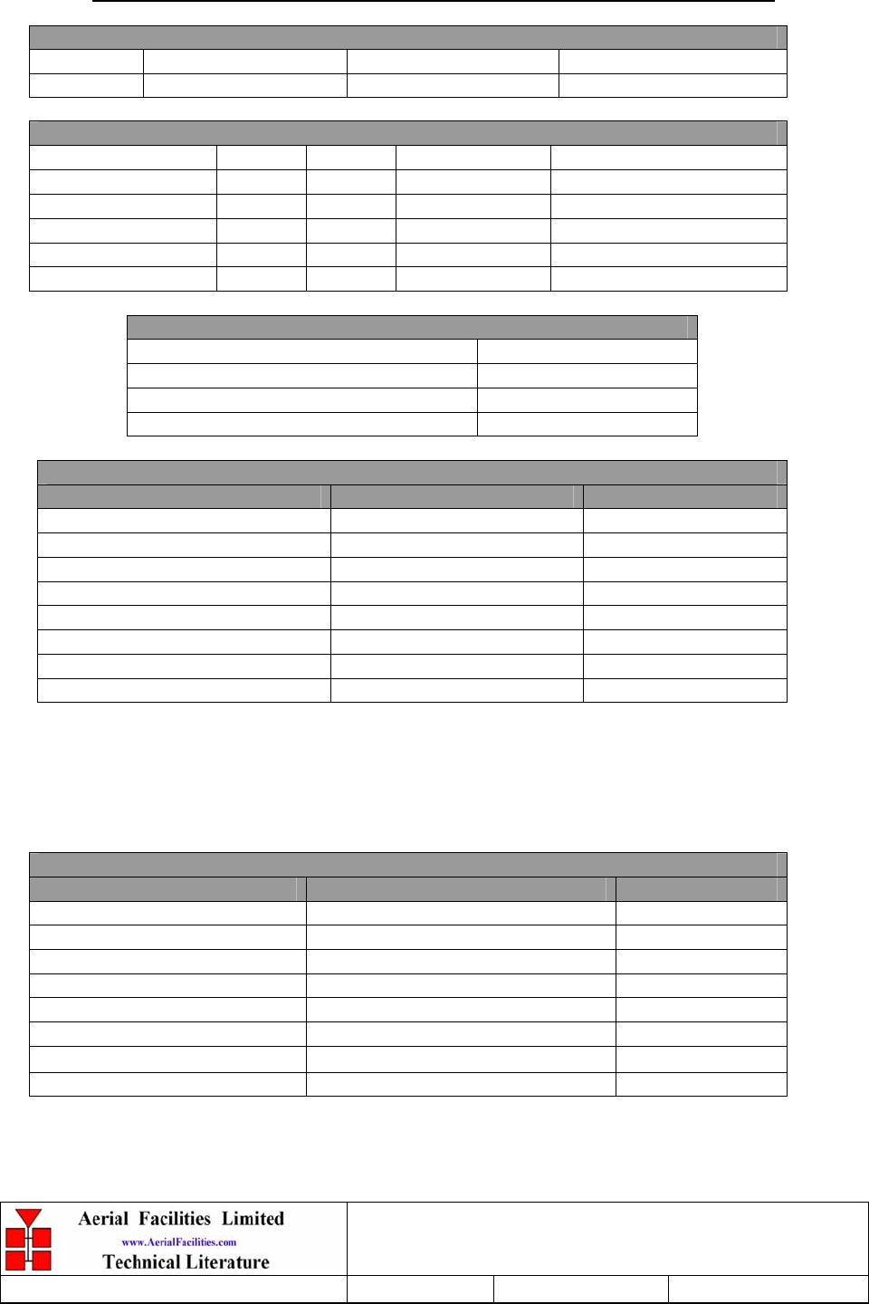
APPENDIX A INITIAL EQUIPMENT SET-UP CALCULATIONS
GENERAL INFORMATION
Site Name: Client Name:
Date: AFL Equip. Model Nō.
ANTENNA SYSTEMS
Model Gain Azimuth Comments
A - Service Antenna
B – Donor Antenna
Type Loss Length Comments
C – Service Feeder
D – Donor Feeder
INITIAL PARAMETERS
E – CE Output Power dBm
F – Antenna Isolation dB
G – Input signal level from donor BTS dBm
Operating Voltage V
DOWNLINK CALCULATIONS
Parameter Comments Value
Input signal level (G) dBm
CE max. o/p power (E) dBm
Gain setting E - G dB
Isolation required (Gain + 10dB) dB
Service antenna gain (A) dB
Service antenna feeder loss (C) dB
Effective radiated power (ERP) E+A-C dBm
Attenuator setting CE gain-gain setting dB
If the input signal level in the uplink path is known and steady, use the following calculation
table to determine the gain setting. If the CE features Automatic Gain Control the attenuator
should be set to zero and if not, then the attenuation setting for both uplink and downlink
should be similar.
UPLINK CALCULATIONS
Parameter Comments Value
Input signal level dBm
CE max. o/p power (E) dBm
Gain setting dB
Required isolation dB
Donor antenna gain (B) dB
Donor antenna feeder loss (D) dB
Effective radiated power (ERP) E+B-D dBm
Attenuator setting (CE gain-gain setting) dB