PBE Europe as Axell Wireless 60-1661SERIES UHF Channelised AIR Interface type 60-166101 User Manual 60 166101HBKM
Axell Wireless UHF Channelised AIR Interface type 60-166101 60 166101HBKM
UserManual.wiki
>
PBE Europe as Axell Wireless
>
60 1661SERIES User Manual
User guide
Navigation menu
Upload a User Manual
Namespaces
Wiki Guide
HTML
PDF
Info
Views
User Manual
Discussion / Help
Navigation
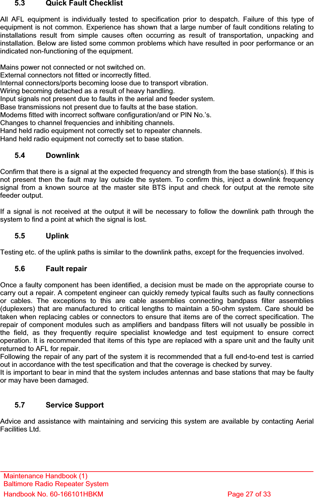
![Maintenance Handbook (1) Baltimore Radio Repeater System Handbook No. 60-166101HBKM Page 26 of 33 5. FAULT FINDING / MAINTENANCE 5.1 Tools & Test Equipment The minimum tools and test equipment needed to successfully service this AFL product are as follows:- Spectrum analyser: 100kHz to 2GHz (Dynamic range = 90dB). Signal Generator: 30MHz to 2GHz (-120dBm to 0dBm o/p level). Attenuator: 20dB, 10W, DC-2GHz, (N male – N female). Test Antenna: Yagi or dipole for operating frequency. Digital multi-meter: Universal Volt-Ohm-Amp meter. Test cable x 2: N male – N male, 2M long RG214. Test cable x 2: SMA male – N male, 1m long RG223. Hand tools: Philips #1&2 tip screwdriver. 3mm flat bladed screwdriver. SMA spanner and torque setter. 5.2 Basic Fault Finding In the event that the performance of the system is suspect, a methodical and logical approach to the problem will reveal the cause of the difficulty. The system consists of separate modules in a wall-mounted enclosure. Transmissions from the main base stations are passed though the system to the mobile radio equipment; this could be a handheld radio or a transceiver in a vehicle. This path is referred to as the downlink. The return signal path from mobile radio equipment to the base station is referred to as the uplink.The first fault finding operation is to check the alarms of each of the active units and determine that the power supplies to the equipment are connected and active. This can be achieved remotely (via CEMS, the RS232 Coverage Enhancement Management System, if fitted), or locally with the front panel LEDs. The green LED on the door should be illuminated, while the red alarm indicator should be off. If an alarm is on, then that individual module must be isolated and individually tested against the original test specification. The individual amplifier units have a green LED showing through a hole in their cover/lid, which is illuminated if the unit is working correctly. (Without active power supplies there can be no alarm LED indicators, however without DC power, the fail-safe summary alarm system [normally closed relay contacts] will be an open circuit, thereby activating any externally connected system.) If an amplifier is suspect, check the DC power supply to the unit. If no other fault is apparent use a spectrum analyser to measure the incoming signal level at the input and then after reconnecting the amplifier input, measure the output level. Consult with the system diagram to determine the expected gain and compare result. In the event that there are no alarms on and all units appear to be functioning it will be necessary to test the system in a systematic manner to confirm correct operation.](https://usermanual.wiki/PBE-Europe-as-Axell-Wireless/60-1661SERIES/User-Guide-714737-Page-26.png)
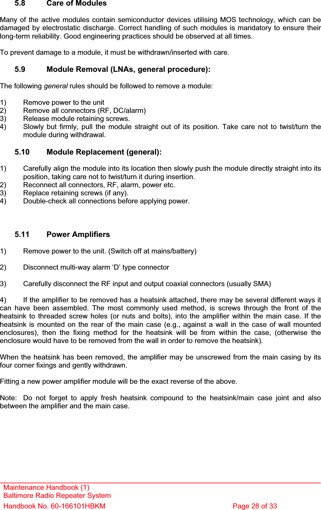
![6.3 EC Declaration of Conformity In accordance with BS EN ISO/IEC 17050-1&-2:2004 Aerial Facilities Limited Aerial House Asheridge Road CheshamBuckinghamshire HP5 2QD United Kingdom DECLARES, UNDER OUR SOLE RESPONSIBILITY THAT THE FOLLOWING PRODUCT: PRODUCT PART NO[S] 60-166101PRODUCT DESCRIPTION Baltimore Transit radio repeaters IN ACCORDANCE WITH THE FOLLOWING DIRECTIVES: 1999/5/EC The Radio & Telecommunications Terminal Equipment Directive Annex V and its amending directivesHAS BEEN DESIGNED AND MANUFACTURED TO THE FOLLOWING STANDARD[S] OR OTHERNORMATIVE DOCUMENT[S]: BS EN 60950 Information technology equipment. Safety. General requirementsETS EN 301 489-1 EMC standard for radio equipment and services.Part 1. Common technical requirements I hereby declare that the equipment named above has been designed to comply with the relevant sections of the above referenced specifications. The unit complies with all essential requirements of the Directives. SIGNEDB S BARTON TECHNICAL DIRECTOR DATE: 16/02/2006Registered Office: Aerial House, Asheridge Road, Chesham, Buckinghamshire, HP5 2QD England Registered No. 4042808 (England) www.aerialfacilities.comMaintenance Handbook (1) Baltimore Radio Repeater System Handbook No. 60-166101HBKM Page 32 of 33](https://usermanual.wiki/PBE-Europe-as-Axell-Wireless/60-1661SERIES/User-Guide-714737-Page-32.png)