PBE Europe as Axell Wireless 60-1742SERIES 60-1742 Series Repeater User Manual 60 174202HBK
Axell Wireless 60-1742 Series Repeater 60 174202HBK
Manual

Axell Wireless Limited
Technical Literature
MWAA Primary F/O Head End Documentation
B010 IF BDA 60-174202
Document Number 60-174202HBK Issue No. 1 Date 23/07/2009 Page 1 of 24
MWAA Primary F/O Head End Documentation
B010 IF BDA 60-174202
User Handbook
for
Communications Technology Services
AWL Works Order Q117141
Axell Wireless UK
Aerial House
Asheridge Road
Chesham, Buckinghamshire
HP5 2QD, United Kingdom
Tel: + 44 (0) 1494 777000
Fax: + 44 (0) 1494 777002
info@axellwireless.com
www.axellwireless.com
Axell Wireless Sweden
Box 7139
174 07 Sundbyberg
Sweden
Tel: + 46 (0) 8 475 4700
Fax: + 46 (0) 8 475 4799

Axell Wireless Limited
Technical Literature
MWAA Primary F/O Head End Documentation
B010 IF BDA 60-174202
Document Number 60-174202HBK Issue No. 1 Date 23/07/2009 Page 2 of 24
Table of Contents
1. Introduction .................................................................................................................................. 3
1.1. Scope and Purpose of Document ..........................................................................................3
1.2. Limitation of Liability Notice.................................................................................................... 3
2. Safety Considerations .................................................................................................................. 4
2.1. Earthing of Equipment............................................................................................................ 4
2.2. Electric Shock Hazard............................................................................................................ 4
2.3. RF Radiation Hazard.............................................................................................................. 4
2.4. Lifting and other Health and Safety Recommendations ......................................................... 4
2.5. Chemical Hazard.................................................................................................................... 5
2.6. Laser Safety ........................................................................................................................... 5
2.7. Emergency Contact Numbers ................................................................................................ 5
3. MWAA Primary Headend B010 IF BDA 60-174202..................................................................... 6
3.1. 60-174202 List of Major Sub-Components............................................................................. 6
3.2. 60-174202 System Diagram................................................................................................... 7
3.3. 60-174202 Auxiliary Alarm Wiring Diagram ........................................................................... 8
3.4. 60-174202 Front Panel........................................................................................................... 9
3.5. 60-174202 Rear Panel ......................................................................................................... 10
4. Installation – General Notes.......................................................................................................11
4.1 General Remarks .................................................................................................................11
4.2 Electrical Connections..........................................................................................................11
4.3 RF Connections....................................................................................................................11
4.3.1. Termination of Unused Ports................................................................................................ 12
4.4 Optical Connections .............................................................................................................12
4.5 Commissioning..................................................................................................................... 12
4.6 Antenna Installation & Gain Calculations ............................................................................. 12
4.7 Antenna Isolation..................................................................................................................13
5. Maintenance............................................................................................................................... 14
5.1. Fault Finding......................................................................................................................... 14
5.1.1. Quick Fault Checklist........................................................................................................ 14
5.1.2 Fault Isolation ................................................................................................................... 14
5.1.3 Downlink........................................................................................................................... 15
5.1.4 Uplink ............................................................................................................................... 15
5.1.5 Checking service .............................................................................................................. 15
5.1.6 Fault repair ....................................................................................................................... 15
5.1.7 Service Support................................................................................................................15
5.2 Tools & Test Equipment ....................................................................................................... 16
5.3 Care of Modules................................................................................................................... 16
5.3.1 General Comments .......................................................................................................... 16
5.3.2 LNA Replacement (general procedure)............................................................................ 16
5.3.3 Module Replacement (general procedure)....................................................................... 16
5.3.4 Power Amplifier Replacement (general procedure) ......................................................... 17
5.3.5 Low Power Amplifier Replacement (general procedure).................................................. 17
5.3.6 Module Transportation: .................................................................................................... 18
Appendix A........................................................................................................................................... 19
A.1. Glossary of Terms used in this document ............................................................................ 19
A.2. Key to Drawing Symbols used in this document ..................................................................20
A.3. EC Declaration of Conformity............................................................................................... 21
A.4. Waste Electrical and Electronic Equipment (WEEE) Notice ................................................ 22
A.5. Document Amendment Record ............................................................................................ 23
Appendix B........................................................................................................................................... 24
B.1 Initial Equipment Set-Up Calculations.................................................................................. 24

Axell Wireless Limited
Technical Literature
MWAA Primary F/O Head End Documentation
B010 IF BDA 60-174202
Document Number 60-174202HBK Issue No. 1 Date 23/07/2009 Page 3 of 24
1. Introduction
1.1. Scope and Purpose of Document
This handbook is for use solely with the equipment identified by the Axell Wireless Limited (AWL) Part
Number shown on the front cover. It is not to be used with any other equipment unless specifically
authorised by AWL. This is a controlled release document and, as such, becomes a part of the Axell
Wireless Total Quality Management System. Alterations and modification may therefore only be
performed by Axell Wireless.
AWL recommends that the installer of this equipment familiarise themselves with the safety and
installation procedures contained within this document before installation commences.
The purpose of this handbook is to provide the user/maintainer with sufficient information to service
and repair the equipment to the level agreed. Maintenance and adjustments to any deeper level must
be performed by AWL, normally at the company’s repair facility in Chesham, England.
This handbook has been prepared in accordance with BS 4884, and AWL’s Quality procedures, which
maintain the company’s registration to BS EN ISO 9001:2000 and to the R&TTE Directive of the
European Parliament. Copies of the relevant certificates and the company Quality Manual can be
supplied on application to the Operations Support Director (see section 2.7.).
This document fulfils the relevant requirements of Article 6 of the R&TTE Directive.
1.2. Limitation of Liability Notice
This manual is written for the use of technically competent operators/service persons. No liability is
accepted by AWL for use or misuse of this manual, the information contained therein, or the
consequences of any actions resulting from the use of the said information, including, but not limited
to, descriptive, procedural, typographical, arithmetical, or listing errors.
Furthermore, AWL does not warrant the absolute accuracy of the information contained within this
manual, or its completeness, fitness for purpose, or scope.
AWL has a policy of continuous product development and enhancement, and as such, reserves the
right to amend, alter, update and generally change the contents, appearance and pertinence of this
document without notice.
All AWL products carry a twelve month warranty from date of shipment. The warranty is expressly on
a return to base repair or exchange basis and the warranty cover does not extend to on-site repair or
complete unit exchange.
Axell Wireless Limited
Technical Literature
MWAA Primary F/O Head End Documentation
B010 IF BDA 60-174202
Document Number 60-174202HBK Issue No. 1 Date 23/07/2009 Page 4 of 24
2. Safety Considerations
2.1. Earthing of Equipment
Equipment supplied from the mains must be connected to grounded outlets and earthed
in conformity with appropriate local, national and international electricity supply and
safety regulations.
2.2. Electric Shock Hazard
The risk of electrical shocks due to faulty mains driven power supplies whilst
potentially ever present in any electrical equipment, would be minimised by adherence
to good installation practice and thorough testing at the following stages:
All test equipment must be in good working order prior to its use. High current power supplies can be
dangerous because of the possibility of substantial arcing. Always switch off during disconnection and
reconnection.
2.3. RF Radiation Hazard
RF radiation, (especially at UHF frequencies) arising from transmitter outputs
connected to AWL’s equipment, must be considered a safety hazard.
This condition might only occur in the event of cable disconnection, or because a
‘spare’ output has been left un-terminated. Either of these conditions would impair the
system’s efficiency. No investigation should be carried out until all RF power sources have been
removed. This would always be a wise precaution, despite the severe mismatch between the
impedance of an N type connector at 50Ω, and that of free space at 377Ω, which would severely
compromise the efficient radiation of RF power. Radio frequency burns could also be a hazard, if any
RF power carrying components were to be carelessly touched!
Antenna positions should be chosen to comply with requirements (both local & statutory) regarding
exposure of personnel to RF radiation. When connected to an antenna, the unit is capable of
producing RF field strengths, which may exceed guideline safe values especially if used with
antennas having appreciable gain. In this regard the use of directional antennas with backscreens
and a strict site rule that personnel must remain behind the screen while the RF power is on, is
strongly recommended.
Where the equipment is used near power lines or in association with temporary masts not having
lightning protection, the use of a safety earth connected to the case-earthing bolt is strongly advised.
2.4. Lifting and other Health and Safety Recommendations
Certain items of AWL equipment are heavy and care should be taken when lifting them
by hand. Ensure that a suitable number of personnel, appropriate lifting apparatus
and appropriate personal protective equipment is used especially when installing
Equipment above ground e.g. on a mast or pole and manual handling precautions
relevant to items of the weight of the equipment being worked on must be observed at
all times when handling, installing or dismounting this equipment.
a) Original assembly.
b) Commissioning.
c) Regular intervals, thereafter.
Axell Wireless Limited
Technical Literature
MWAA Primary F/O Head End Documentation
B010 IF BDA 60-174202
Document Number 60-174202HBK Issue No. 1 Date 23/07/2009 Page 5 of 24
2.5. Chemical Hazard
Beryllium Oxide, also known as Beryllium Monoxide, or Thermalox™, is sometimes
used in devices within equipment produced by Axell Wireless Ltd. Beryllium oxide dust
can be toxic if inhaled, leading to chronic respiratory problems. It is harmless if
ingested or by contact.
Products that contain beryllium are load terminations (dummy loads) and some power amplifiers.
These products can be identified by a yellow and black “skull and crossbones” danger symbol (shown
above). They are marked as hazardous in line with international regulations, but pose no threat under
normal circumstances. Only if a component containing beryllium oxide has suffered catastrophic
failure, or exploded, will there be any danger of the formation of dust. Any dust that has been created
will be contained within the equipment module as long as the module remains sealed. For this reason,
any module carrying the yellow and black danger sign should not be opened. If the equipment is
suspected of failure, or is at the end of its life-cycle, it must be returned to Axell Wireless Ltd. for
disposal.
To return such equipment, please contact the Operations Support Department, who will give you a
Returned Materials Authorisation (RMA) number. Please quote this number on the packing
documents, and on all correspondence relating to the shipment.
PolyTetraFluoroEthylene, (P.T.F.E.) and P.T.F.E. Composite Materials
Many modules/components in AWL equipment contain P.T.F.E. as part of the RF insulation barrier.
This material should never be heated to the point where smoke or fumes are evolved. Any person
feeling drowsy after coming into contact with P.T.F.E. especially dust or fumes should seek medical
attention.
2.6. Laser Safety
General good working practices adapted from
EN60825-2: 2004/ EC 60825-2:2004
Do not stare with unprotected eyes or with any unapproved optical device at the fibre
ends or connector faces or point them at other people, Use only approved filtered or attenuating
viewing aids.
Any single or multiple fibre end or ends found not to be terminated (for example, matched, spliced)
shall be individually or collectively covered when not being worked on. They shall not be readily
visible and sharp ends shall not be exposed.
When using test cords, the optical power source shall be the last connected and the first
disconnected; use only approved methods for cleaning and preparing optical fibres and optical
connectors.
Always keep optical connectors covered to avoid physical damage and do not allow any dirt/foreign
material ingress on the optical connector bulkheads.
The optical fibre jumper cable minimum bend radius is 3cm; bending to a smaller radius may result in
optical cable breakage and excessive transmission losses.
Caution: The FO units are NOT weather proof.
2.7. Emergency Contact Numbers
The AWL Operations Support Department can be contacted on:
Telephone +44 (0)1494 777000
Fax. +44 (0)1494 777002
e-mail qa@axellwireless.com
Axell Wireless Limited
Technical Literature
MWAA Primary F/O Head End Documentation
B010 IF BDA 60-174202
Document Number 60-174202HBK Issue No. 1 Date 23/07/2009 Page 6 of 24
3. MWAA Primary Headend B010 IF BDA 60-174202
There are two 60-174202 IF BDAs in Primary F/O Head End Cab. 1 - 60-174201, both BDAs are
housed in rack 2.
MWAA Primary Headend B010 IF BDA (1) (Loudoun County 1) 60-174202
MWAA Primary Headend B010 IF BDA (2) (Loudoun County 2) 60-174202
Each 60-174202 IF BDA is an 8U, 19” rack mount tray and houses RF filtering and amplification
modules.
RF signals are received from off-air antennas in the Downlink direction, filtered and amplified and sent
via 60-174204 MWAA Primary B010 Splitter/Alarm Interface Shelf to the Fibre Optic Interface in
MWAA Primary F/O Head End BDA CAB 2.
RF signals are received in the Uplink direction from the Fibre Optic Interface in MWAA Primary F/O
Head End BDA CAB 2, via 60-174204 MWAA Primary B010 Splitter/Alarm Interface Shelf, filtered and
amplified and then passed to an antenna.
60-174202 IF BDA (1) (Loudoun County 1) receives its downlink signal from and sends its Uplink
signal to the “Ramp Tower” antenna.
60-174202 IF BDA (2) (Loudoun County 2) receives its downlink signal from and sends its Uplink
signal to the “Bull Run Tower” antenna.
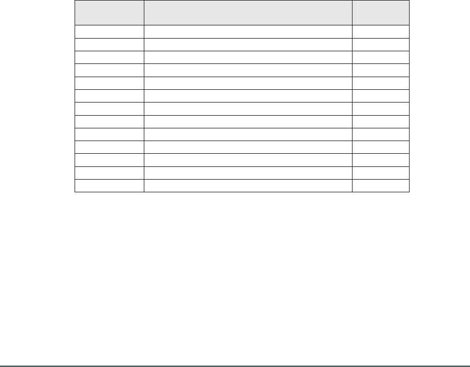
3.1. 60-174202 List of Major Sub-Components
Component
Part
Component Part Description Qty Per
Assembly
02-005801 Bandpass Filter 1
02-005805 Bandpass Filter 1
10-000701 Variable Switched Attenuator 0 to 30dB 2
11-005902 Low Noise Amplifier 2
11-006702 Low Noise Amplifier 2
12-018601 5W Power Amplifier 2
16-096601 Duplexer Module 1
17-001117 AGC Detector Module 2
17-001201 AGC Attenuator Module 2
17-003043 Channel Selectivity Module 2
17-011501 Channel Control Module 2
20-001601 12V Dual Relay Board 1
80-008901 12V Relay Assembly 1
Axell Wireless Limited
Technical Literature
MWAA Primary F/O Head End Documentation
B010 IF BDA 60-174202
Document Number 60-174202HBK Issue No. 1 Date 23/07/2009 Page 7 of 24
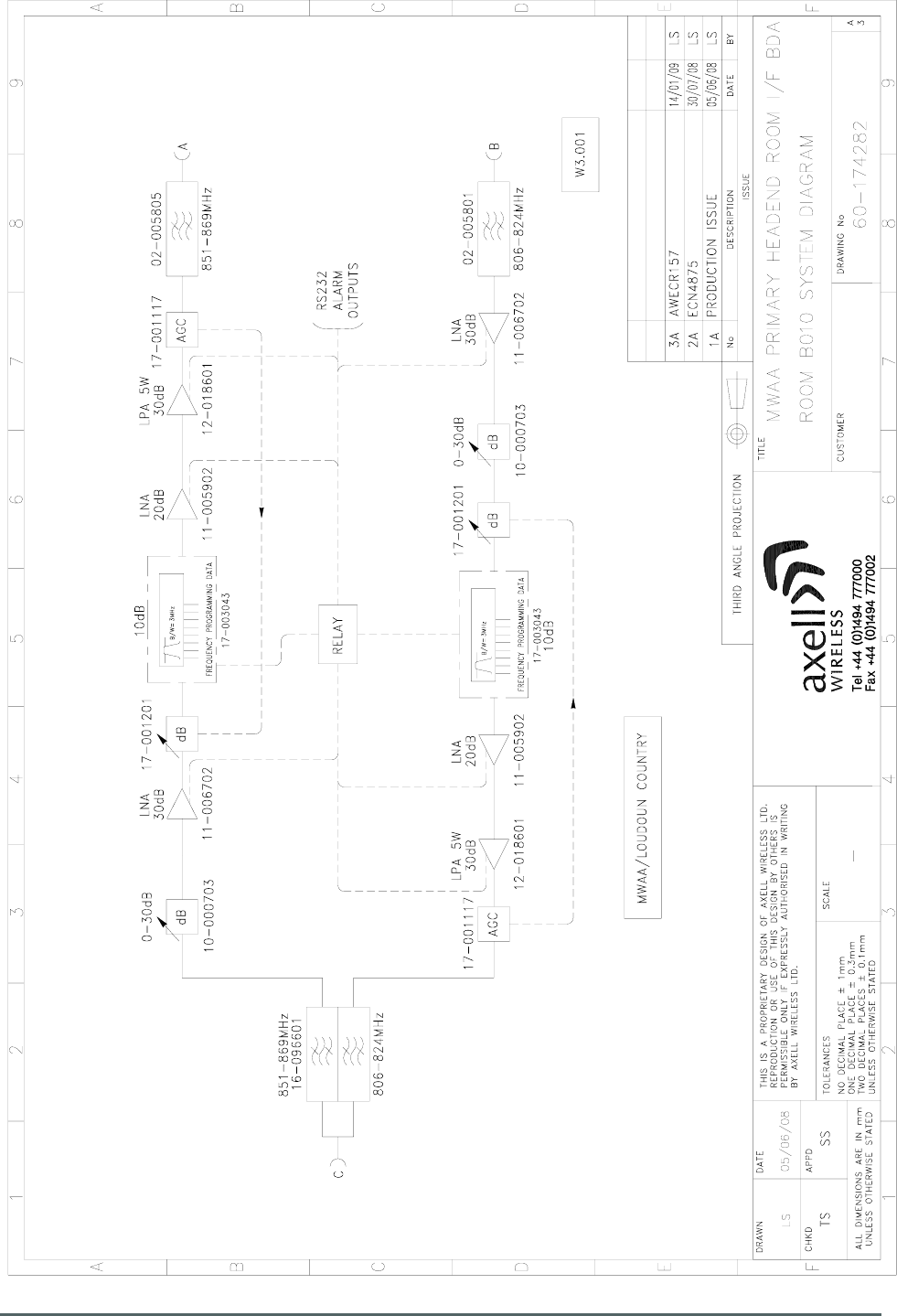
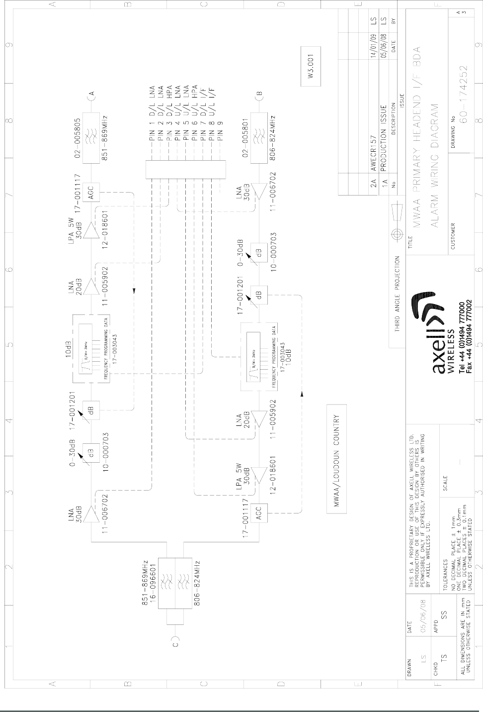
3.2. 60-174202 System Diagram
Drawing Number 60-174282
Axell Wireless Limited
Technical Literature
MWAA Primary F/O Head End Documentation
B010 IF BDA 60-174202
Document Number 60-174202HBK Issue No. 1 Date 23/07/2009 Page 8 of 24
3.3. 60-174202 Auxiliary Alarm Wiring Diagram
Drawing Number 60-174252
Axell Wireless Limited
Technical Literature
MWAA Primary F/O Head End Documentation
B010 IF BDA 60-174202
Document Number 60-174202HBK Issue No. 1 Date 23/07/2009 Page 9 of 24
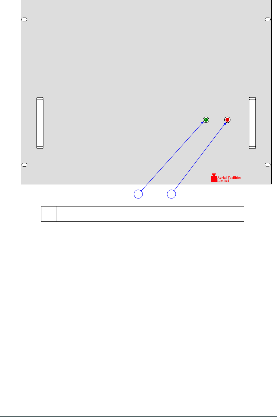
POWER ALARM
A B
3.4. 60-174202 Front Panel
A Green LED “POWER ON” Illuminated during normal operation.
B Red LED “ALARM” Illuminated during alarm state.
Axell Wireless Limited
Technical Literature
MWAA Primary F/O Head End Documentation
B010 IF BDA 60-174202
Document Number 60-174202HBK Issue No. 1 Date 23/07/2009 Page 10 of 24
0dB 0dB 0dB 0dB
2dB 4dB 8dB 16dB
0dB 0dB 0dB 0dB
2dB 4dB 8dB 16dB
UPLINK
ATTENUATOR
DOWNLINK
ATTENUATOR
CB A
12V DC I/P
+ -
FUSE
T6.3A
RS232 ALARM
OUTPUTS
ALARM
PINS 1 - 2
UPLINK
DOWNLINK
SINGLE CHANNEL
CONTROL MODULE
SINGLE CHANNEL
CONTROL MODULE
60-174202
D E ABC
FG L
H
I
J
K
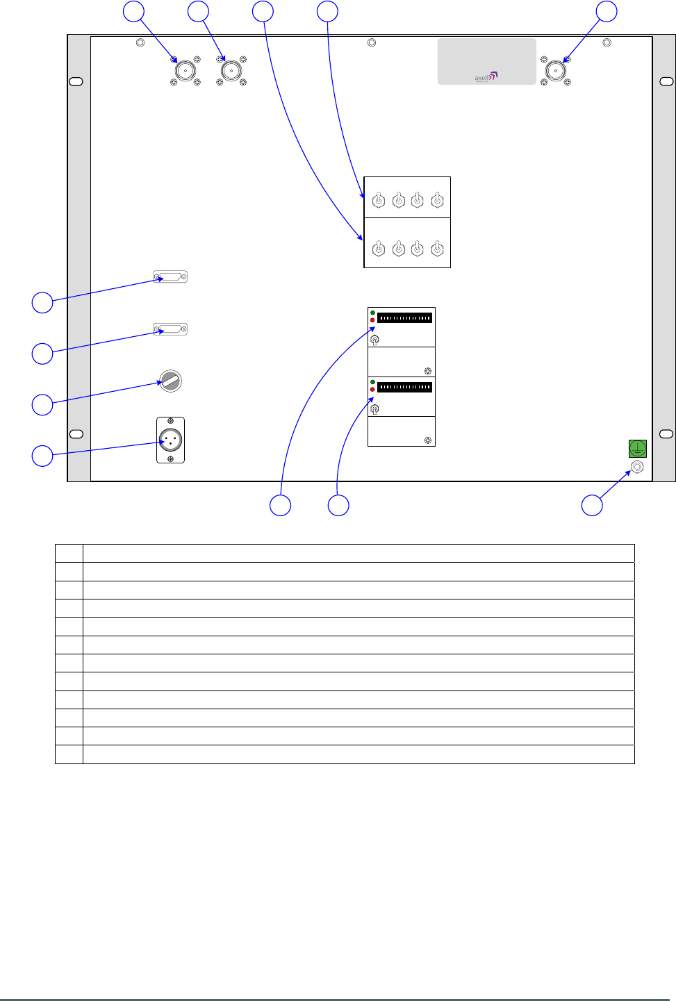
3.5. 60-174202 Rear Panel
A Downlink RF Output to 60-174204 Splitter/Combiner Alarm Interface Shelf
B Uplink RF Input from 60-174204 Splitter/Combiner Alarm Interface Shelf
C Combined input from and output to antenna (see ** below)
D Downlink Variable Switched Attenuator 10-000701
E Uplink Variable Switched Attenuator 10-000701
F Channel control switches for Downlink
G Channel control switches for Uplink
H 12V DC Input from Dual PSU Shelf 13-005301
I 6.3A Fuse for DC input
J Alarm Output to 60-174204 Splitter/Combiner Alarm Interface Shelf
K Auxiliary alarm output
L Earth Connection
Antenna connections **
60-174202 IF BDA (1) (Loudoun County 1) receives its downlink signal from and sends its Uplink
signal to the “Ramp Tower” antenna.
60-174202 IF BDA (2) (Loudoun County 2) receives its downlink signal from and sends its Uplink
signal to the “Bull Run Tower” antenna.

Axell Wireless Limited
Technical Literature
MWAA Primary F/O Head End Documentation
B010 IF BDA 60-174202
Document Number 60-174202HBK Issue No. 1 Date 23/07/2009 Page 11 of 24
4. Installation – General Notes
4.1 General Remarks
When this equipment is initially commissioned, please use the equipment set-up record sheet in
Appendix B. This will help both the installation personnel and Axell Wireless should these figures be
needed for future reference or diagnosis.
Wall Mount equipment
The procedure for installing and commissioning an Axell Wall Mount equipment is generally as
follows:
1) Secure the Repeater in the chosen wall position.
2) Fix the antenna and connect its cables to the Amplifier antenna ports.
3) Connect a suitable mains or battery power supply to the Amplifier
4) Calculate the attenuation settings required for the uplink and the downlink paths, and set the
attenuators as described elsewhere in this document.
5) Switch the equipment mains on with the small switch located inside the Amplifier on the lower
right hand side of the case.
6) If Base Station RF is available, make test calls via the Amplifier to ensure correct operation, if
possible monitoring the signal levels during these calls to ensure that the uplink and downlink
RF levels are as anticipated.
Rack Mount Equipment
The equipment racks must be located on a flat, level surface that is made from a material suitable for
bearing the weight of the rack assembly. If the installer is in any doubt about the suitability of a site it
is recommended that he consult with an appropriately qualified Structural Engineer.
It is important in determining the location of the rack within the room that space is allowed for access
to the front and rear of the equipment. To enable maintenance to be carried out, the doors must be
able to fully open.
The location must be served with a duct to allow the entry of cables into the rack.
4.2 Electrical Connections
It is recommended that the electrical mains connection is made by a qualified electrician, who must be
satisfied that the supply will be the correct voltage and of sufficient capacity.
All electrical and RF connections should be completed and checked prior to power being applied for
the first time.
Ensure that connections are kept clean and are fully tightened.
4.3 RF Connections
Care must be taken to ensure that the correct connections are made with particular attention made to
the base station TX/RX ports. In the event that the base transmitter is connected to the RX output of
the equipment, damage to the equipment will be done if the base station transmitter is then keyed.

Axell Wireless Limited
Technical Literature
MWAA Primary F/O Head End Documentation
B010 IF BDA 60-174202
Document Number 60-174202HBK Issue No. 1 Date 23/07/2009 Page 12 of 24
4.3.1. Termination of Unused Ports
In the event that any RF ports are unused (available for future expansion) these ports must be kept
terminated with the load terminations supplied by Axell for that purpose
Ensure that connections are kept clean and are fully tightened.
4.4 Optical Connections
The optical input and output ports will be shown in the system drawings. The ports are supplied with a
green plastic cover, which must be removed prior to the connection of the fibre cable. Ensure that
transmitter and receiver fibre cable are identified to prevent misconnection. At the master site, the
fibre transmitters are in the downlink path with the receivers in the uplink. At the remote sites the fibre
transmitters are in the uplink with the receivers in the downlink.
Always ensure that connections are kept clean and are fully tightened.
4.5 Commissioning
Once all connections are made the equipment is ready for commissioning.
To commission the system the test equipment detailed in Section 5.2. will be required.
Using the system diagrams and the end-to-end test specification (supplied with the equipment), the
equipment should be tested to ensure correct operation. Typical RF levels that are not listed in the
end-to-end specification, such as input levels to the fibre transmitters are detailed in the maintenance
section of this manual.
On initial power up the system alarm indicators on the front door of the equipment should be checked.
A green LED on each unit with a power supply to it illuminates to indicate that the power supply is
connected to the unit A red LED illuminated indicates a fault in that particular unit that must be
investigated before proceeding with the commissioning.
In the event that any part of the system does not function correctly as expected, check all connections
to ensure that they are to the correct port, that the interconnecting cables are not faulty and that they
are tightened. The majority of commissioning difficulties arise from problems with the interconnecting
cables and connectors.
4.6 Antenna Installation & Gain Calculations
1) The equipment requires two antennas, one a highly directional Yagi or similar directed towards
the donor cell base station, and one a leaky feeder, omni-directional antenna or Yagi to cover
the area in which the mobiles are to be served.
2) The maximum gain at which the equipment can be set is limited by the isolation that can be
achieved between these two antennas. Therefore when the antennas have been installed,
inject a signal (at a known power level) into one of them and measure the signal level received
by the other antenna on a spectrum analyser. The isolation can then be calculated as the
difference between these two figures. The gain in each path of the equipment should be set at
least 10 dB below this figure, using attenuators as described below in paragraph 5.
3) Also measure the received signal from the donor cell at the input to the equipment (base port).
The gain of the equipment downlink path should be set such the donor site will not overload
the equipment amplifiers. It is recommended that the input level should be less than -50dBm
at the input of the equipment (Base Port). (This figure is assuming maximum gain, and may be
increased by the value of the attenuator fitted in the downlink path.)
Axell Wireless Limited
Technical Literature
MWAA Primary F/O Head End Documentation
B010 IF BDA 60-174202
Document Number 60-174202HBK Issue No. 1 Date 23/07/2009 Page 13 of 24
4) Ensure that the mobile facing antenna has at least 70dB isolation from the nearest mobile.
(This is usually easily achieved when using a leaky feeder.)
5) The equipment gain is set by setting the variable switched attenuators in each path (uplink and
downlink) refer to the photographs and layout drawings for the exact attenuator locations).
Note that the uplink (mobile to base) and downlink (base to mobile) path gains are set
independently. This allows the paths to have different gains if required to set the correct output
power levels.
6) It is recommended that the gains are set such that the Downlink channel output levels from the
equipment are typically +30dBm per channel
(Input level + Gain = Output level).
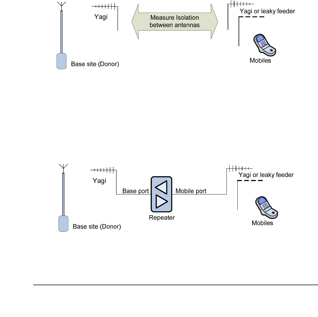
4.7 Antenna Isolation
A). First set up the antennas and measure the isolation between them
B). Install the equipment with gain set 10dB below the isolation figure obtained above

Axell Wireless Limited
Technical Literature
MWAA Primary F/O Head End Documentation
B010 IF BDA 60-174202
Document Number 60-174202HBK Issue No. 1 Date 23/07/2009 Page 14 of 24
5. Maintenance
5.1. Fault Finding
5.1.1. Quick Fault Checklist
All Axell equipment is individually tested to specification prior to despatch. Failure of this type of
equipment is not common. Experience has shown that a large number of fault conditions relating to
tunnel installations result from simple causes often occurring as result of transportation, unpacking
and installation. Below are listed some common problems which have resulted in poor performance or
an indicated non-functioning of the equipment.
• Mains power not connected or not switched on.
• External connectors not fitted or incorrectly fitted.
• Internal connectors becoming loose due to transport vibration.
• Wiring becoming detached as a result of heavy handling.
• Input signals not present due to faults in the antenna and feeder system.
• Base transmissions not present due to fault at the base station.
• Modems fitted with incorrect software configuration.
• Changes to channel frequencies and inhibiting channels.
• Hand held radio equipment not set to repeater channels.
• Hand held radio equipment not set to correct base station.
5.1.2 Fault Isolation
In the event that the performance of the system is suspect, a methodical and logical approach to the
problem will reveal the cause of the difficulty.
Transmissions from the main base stations are passed though the system to the mobile radio
equipment; this could be a handheld radio or a transceiver in a vehicle. This path is referred to as the
downlink. The return signal path from the mobile radio equipment to the base station is referred to as
the uplink.
The first operation is to check the alarms of each of the active units and determine that the power
supplies to the equipment are connected and active.
This can be achieved remotely (via CEMS, the RS232 Coverage Enhancement Management System,
if fitted), or locally with the front door LEDs. The green LED on the front doors or front panels should
be illuminated, while the red alarm indicators should be off. If an Alarm is on, then that unit must be
tested against the original test specification.
If an amplifier is suspect, check the power supply to the unit. If no other fault is apparent use a
spectrum analyser to measure the incoming signal level at the input and then after reconnecting the
amplifier input, measure the output level. Consult with the system diagram to determine the expected
gain and compare result.
In the event that there are no alarms on and all units appear to be functioning it will be necessary to
test the system in a systematic manner to confirm correct operation.

Axell Wireless Limited
Technical Literature
MWAA Primary F/O Head End Documentation
B010 IF BDA 60-174202
Document Number 60-174202HBK Issue No. 1 Date 23/07/2009 Page 15 of 24
5.1.3 Downlink
Confirm that there is a signal at the expected frequency and strength from the base station. If this is
not present then the fault may lay outside the system. To confirm this, inject a downlink frequency
signal from a known source at the master site BTS input and check for output at the remote site
feeder output.
If a signal is not received at the output it will be necessary to follow the downlink path through the
system to find a point at which the signal is lost. The expected downlink output for the given input can
be found in the end-to-end test specification.
5.1.4 Uplink
Testing the uplink involves a similar procedure to the downlink except that the frequencies used are
those transmitted by the mobile equipment.
5.1.5 Checking service
Following the repair of any part of the system it is recommended that a full end-to-end test is carried
out in accordance with the test specification and that the coverage is checked by survey.
It is important to bear in mind that the system includes a radiating cable network and base stations
that may be faulty or may have been damaged.
5.1.6 Fault repair
Once a faulty component has been identified, a decision must be made on the appropriate course to
carry out a repair. A competent engineer can quickly remedy typical faults such as faulty connections
or cables. The exceptions to this are cable assemblies connecting bandpass filter assemblies that are
manufactured to critical lengths to maintain a 50-ohm system.
Care should be taken when replacing cables or connectors to ensure that items are of the correct
specification. The repair of component modules such as amplifiers and bandpass filters will not
usually be possible in the field, as they frequently require specialist knowledge and test equipment to
ensure correct operation. It is recommended that items of this type are replaced with a spare unit and
the faulty unit returned to Axell Wireless for repair.
5.1.7 Service Support
Advice and assistance with maintaining and servicing this system are available by contacting
Axell Wireless Ltd., see section 2.7.
NOTE
Individual modules are not intended to be repaired on site and attempts at repair will
invalidate active warranties. Company policy is that individual modules should be repaired
by replacement. Axell Wireless Ltd. maintains a level of stock of most modules which can
usually be despatched at short notice to support this policy.

Axell Wireless Limited
Technical Literature
MWAA Primary F/O Head End Documentation
B010 IF BDA 60-174202
Document Number 60-174202HBK Issue No. 1 Date 23/07/2009 Page 16 of 24
5.2 Tools & Test Equipment
The minimum tools and test equipment needed to successfully service this Axell Wireless product
are as follows:-
Spectrum analyser 100kHz to 2GHz (Dynamic range = 90dB).
Signal Generator 30MHz to 2GHz (-120dBm to 0dBm o/p level).
Attenuator 20dB, 10W, DC-2GHz, (N male – N female).
Test Antenna Yagi or dipole for operating frequency.
Optical Power Meter 1300 – 1560nM (-40 - +10dB)
Digital multi-meter Universal Volt-Ohm-Amp meter.
Test cable x 2 N male – N male, 2M long RG214.
Test cable x 2 SMA male – N male, 1m long RG223.
Hand tools Philips #1&2 tip screwdriver.
3mm flat bladed screwdriver.
SMA spanner and torque setter.
5.3 Care of Modules
5.3.1 General Comments
Many of the active modules contain semiconductor devices utilising MOS technology, which can be
damaged by electrostatic discharge. Correct handling of such modules is mandatory to ensure their
long-term reliability.
To prevent damage to a module, it must be withdrawn and inserted with care. The module may have
connectors on its underside, which might not be visible to the service operative.
5.3.2 LNA Replacement (general procedure)
The following general instructions should be followed to remove a module:
1) Remove power to the unit
2) Remove all visible connectors (RF, DC & alarm)
3) Release module retaining screws.
4) Slowly but firmly, pull the module straight out of its position. Take care not to twist/turn the
module during withdrawal. (When the module is loose, care may be needed, as there may be
concealed connections underneath).
5.3.3 Module Replacement (general procedure)
1) Carefully align the module into its location then slowly push the module directly straight into its
position, taking care not to twist/turn it during insertion.
2) Reconnect all connectors, RF, alarm, power etc., (concealed connectors may have to be
connected first).
3) Replace retaining screws (if any).
4) Double-check all connections before applying power.

Axell Wireless Limited
Technical Literature
MWAA Primary F/O Head End Documentation
B010 IF BDA 60-174202
Document Number 60-174202HBK Issue No. 1 Date 23/07/2009 Page 17 of 24
5.3.4 Power Amplifier Replacement (general procedure)
1) Remove power to the unit. (Switch off at mains/battery, or remove DC in connector)
2) Remove alarm wires from alarm screw terminal block or disconnect multi-way alarm
connector.
3) Carefully disconnect the RF input and output coaxial connectors (usually SMA)
If alarm board removal is not required, go to step 5.
4) There is (usually) a plate attached to the alarm board which fixes it to the amplifier, remove its
retaining screws and the alarm board can be withdrawn from the amplifier in its entirety. On
certain types of amplifier the alarm board is not mounted on a dedicated mounting plate; in this
case it will have to firstly be removed by unscrewing it from the mounting pillars, in most
cases, the pillars will not have to be removed before lifting the amplifier.
5) If the amplifier to be removed has a heatsink attached, there may be several different ways it
can have been assembled. The most commonly used method, is screws through the front of
the heatsink to threaded screw holes (or nuts and bolts), into the amplifier within the main
case. If the heatsink is mounted on the rear of the main case (e.g., against a wall in the case
of wall mounted enclosures), then the fixing method for the heatsink will be from within the
case, (otherwise the enclosure would have to be removed from the wall in order to remove the
heatsink).
When the heatsink has been removed, the amplifier may be unscrewed from the main casing by its
four corner fixings and gently withdrawn.
Fitting a new power amplifier module will be the exact reverse of the above.
Note: Do not forget to apply fresh heatsink compound to the heatsink/main case joint and also
between the amplifier and the main case.
5.3.5 Low Power Amplifier Replacement (general procedure)
1) Disconnect the mains power supply and disconnect the 24V dc supply connector for the LPA.
2) Disconnect the RF input and output cables from the LPA.
3) Disconnect the alarm connector.
4) Remove the alarm monitoring wires from (D type connector) pins 9 and 10.
Remove the LPA module by removing the four retaining screws, replace with a new LPA
module and secure it with the screws.
5) Connect the RF cables to the LPA input and output connectors. Reconnect the wires to the
alarm board connector pins 9 and 10.
6) Reconnect the DC supply connector and turn the mains switch on.
Note: Tighten SMA connectors using only a dedicated SMA torque spanner. If SMA connectors are
over-tightened, irreparable damage will occur. Do not use adjustable pliers to loosen/tighten SMA
connectors.
Also take care not to drop or knock the module as this can damage (or misalign in the case of tuned
passive modules) sensitive internal components. Always store the modules in an environmentally
friendly location

Axell Wireless Limited
Technical Literature
MWAA Primary F/O Head End Documentation
B010 IF BDA 60-174202
Document Number 60-174202HBK Issue No. 1 Date 23/07/2009 Page 18 of 24
5.3.6 Module Transportation:
To maintain the operation, performance and reliability of any module it must be stored and
transported correctly. Any module not installed in a whole system must be kept in an anti-static bag or
container. These bags or containers are normally identified by being pink or black, and are often
marked with an ESD label. Any module sent back to Axell Wireless for investigation/repair must be so
protected. Please contact the Axell Wireless Operations Support Department before returning a
module, see section 2.7.

Axell Wireless Limited
Technical Literature
MWAA Primary F/O Head End Documentation
B010 IF BDA 60-174202
Document Number 60-174202HBK Issue No. 1 Date 23/07/2009 Page 19 of 24
Appendix A
A.1. Glossary of Terms used in this document
Repeater or
Cell Enhancer
A Radio Frequency (RF) amplifier which can simultaneously
amplify and re-broadcast Mobile Station (MS) and Base
Transceiver Station (BTS) signals.
Band Selective
Repeater
A Repeater designed for operation on a range of channels within a
specified frequency band.
Channel Selective
Repeater
A Repeater, designed for operation on specified channel(s) within a
specified frequency band. Channel frequencies may be factory set
or on-site programmable.
AC Alternating Current
AGC Automatic Gain Control
BBU Battery Backup Unit
BDA Bi-directional Amplifier
BTS Base Transceiver Station (Base Station)
B/W Bandwidth
CEMS Coverage Enhancement Management System
C/NR Carrier-to-Noise Ratio
DAS Distributed Antenna System
DC Direct Current
Downlink (D/L) RF signals TX from the BTS to the Mobiles
F/O Fibre Optic
GND Ground
ID Identification (Number)
I/P Input
LCX Leaky Coaxial Cable (Leaky Feeder).
LED Light Emitting Diode
LNA Low Noise Amplifier
LPA Low Power Amplifier
Mobile(s) Hand-portable or other “Mobile” RF Transceiver equipment.
MOU Master Optical Unit
MTBF Mean Time Between Failures
N/A Not Applicable
N/C (of Relays) Normally Closed
N/O (of Relays) Normally Open
OFR On Frequency Repeater
OIP3 Output Third Order Intercept Point
O/P Output
P1dB 1dB Compression Point
PA Power Amplifier
RF Radio Frequency
RHNC Relative Humidity, Non Condensing
RSA Receiver/Splitter Amplifier
RX Receiver (Received)
S/N Serial Number
TX Transmitter (Transmitted)
Uplink (U/L) RF signals transmitted from the Mobiles to the BTS
VSWR Voltage Standing Wave Ratio
WDM Wave division multiplex
Date Format Date Format used in this document is dd/mm/yyyy
Axell Wireless Limited
Technical Literature
MWAA Primary F/O Head End Documentation
B010 IF BDA 60-174202
Document Number 60-174202HBK Issue No. 1 Date 23/07/2009 Page 20 of 24
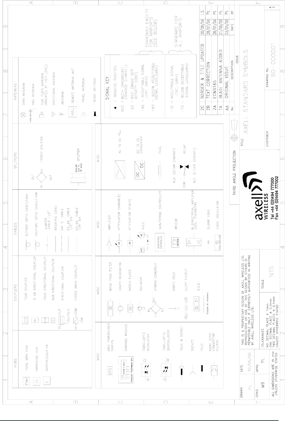
A.2. Key to Drawing Symbols used in this document
Axell Wireless Limited
Technical Literature
MWAA Primary F/O Head End Documentation
B010 IF BDA 60-174202
Document Number 60-174202HBK Issue No. 1 Date 23/07/2009 Page 21 of 24
A.3. EC Declaration of Conformity
In accordance with BS EN ISO/IEC 17050-1&-2:2004
Axell Wireless Limited
Aerial House
Asheridge Road
Chesham
Buckinghamshire HP5 2QD
United Kingdom
Declares, under our sole responsibility that the following product:
MWAA Primary Headend B010 IF BDA 60-174202
IN ACCORDANCE WITH THE FOLLOWING DIRECTIVES:
1999/5/EC The Radio & Telecommunications Terminal Equipment Directive Annex V
and its amending directives
HAS BEEN DESIGNED AND MANUFACTURED TO THE FOLLOWING STANDARD[S] OR
OTHER NORMATIVE DOCUMENT[S]:
BS EN 60950 Information technology equipment.
Safety. General requirements
ETS EN 301 489-1 EMC standard for radio equipment and services.
Part 1. Common technical requirements
I hereby declare that the equipment named above has been designed to comply with the relevant
sections of the above referenced specifications. The unit complies with all essential requirements
of the Directives.
SIGNED
B. S. Barton
Operations Director DATE: 04/12/2008
Registered Office: Aerial House, Asheridge Road, Chesham, Buckinghamshire, HP5 2QD England Registered No. 4042808 (England)
www.axellwireless.com

Axell Wireless Limited
Technical Literature
MWAA Primary F/O Head End Documentation
B010 IF BDA 60-174202
Document Number 60-174202HBK Issue No. 1 Date 23/07/2009 Page 22 of 24
A.4. Waste Electrical and Electronic Equipment (WEEE) Notice
The Waste Electrical and Electronic Equipment (WEEE) Directive became law in
most EU countries during 2005. The directive applies to the disposal of waste
electrical and electronic equipment within the member states of the European
Union.
As part of the legislation, electrical and electronic equipment will feature the
crossed out wheeled bin symbol (see image at left) on the product or in the
documentation to show that these products must be disposed of in accordance
with the WEEE Directive.
In the European Union, this label indicates that this product should not be disposed of with domestic
or "ordinary" waste. It should be deposited at an appropriate facility to enable recovery and recycling.

Axell Wireless Limited
Technical Literature
MWAA Primary F/O Head End Documentation
B010 IF BDA 60-174202
Document Number 60-174202HBK Issue No. 1 Date 23/07/2009 Page 23 of 24
A.5. Document Amendment Record
Issue
No.
Date Incorporated
by
Section
Amended
Reason for new issue
A 23/07/2009 AJS Draft
1 23/07/2009 AJS Issue
Axell Wireless Limited
Technical Literature
MWAA Primary F/O Head End Documentation
B010 IF BDA 60-174202
Document Number 60-174202HBK Issue No. 1 Date 23/07/2009 Page 24 of 24
Appendix B
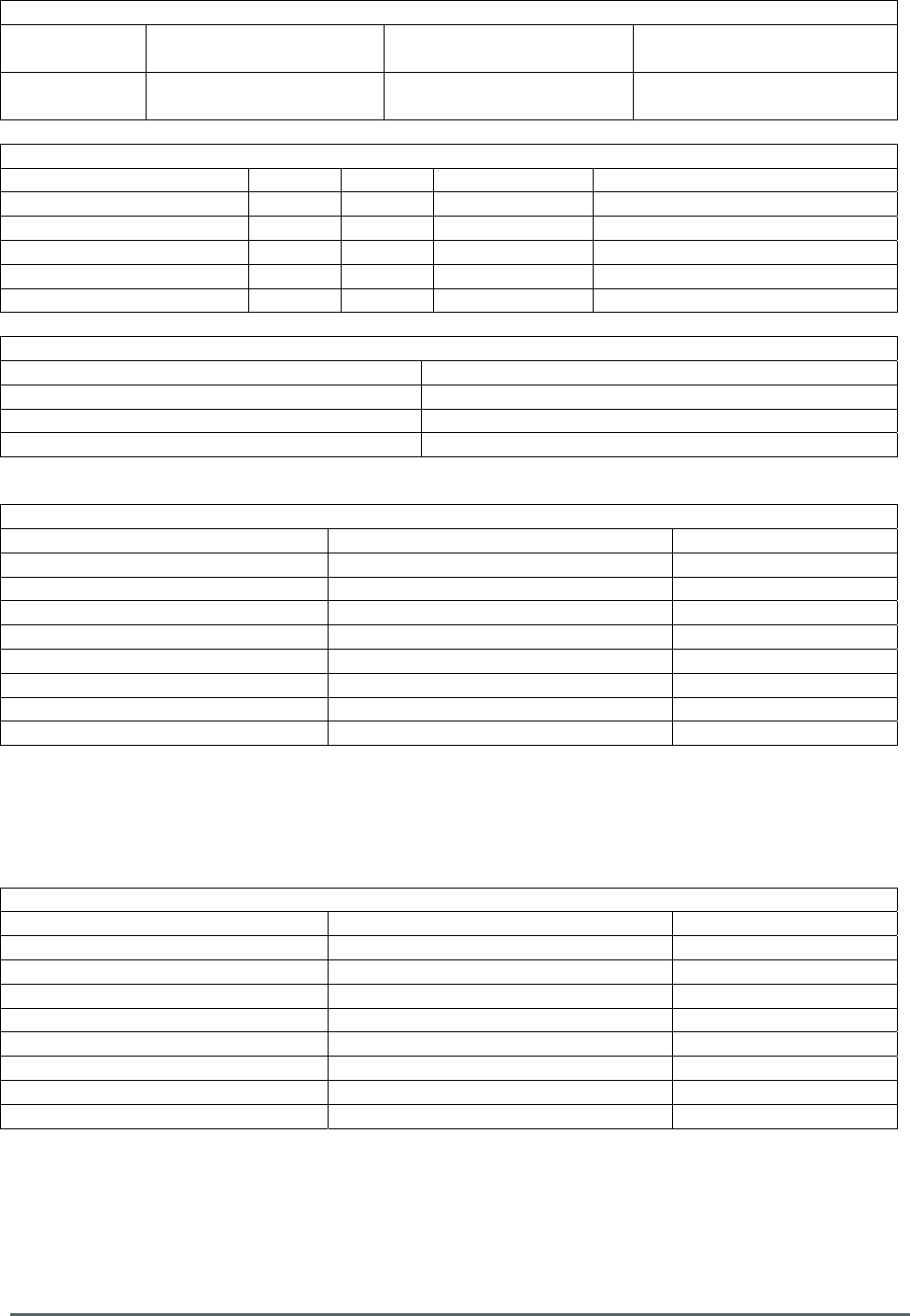
B.1 Initial Equipment Set-Up Calculations
General Information
Site Name:
Client Name:
Date:
AWL Equip. Model No.
Antenna Systems
Model Gain Azimuth Comments
A - Service Antenna
B – Donor Antenna
Type Loss Length Comments
C – Service Feeder
D – Donor Feeder
Initial Parameters
E – CE Output Power dBm
F – Antenna Isolation dB
G – Input signal level from donor BTS dBm
Operating Voltage V
Downlink Calculations
Parameter Comments Value
Input signal level (G) dBm
CE max. o/p power (E) dBm
Gain setting E - G dB
Isolation required (Gain + 10dB) dB
Service antenna gain (A) dB
Service antenna feeder loss (C) dB
Effective radiated power (ERP) E+A-C dBm
Attenuator setting CE gain-gain setting dB
If the input signal level in the uplink path is known and steady, use the following calculation table to
determine the gain setting. If the CE features Automatic Gain Control the attenuator should be set to
zero and if not, then the attenuation setting for both uplink and downlink should be similar.
Uplink Calculations
Parameter Comments Value
Input signal level dBm
CE max. o/p power (E) dBm
Gain setting dB
Required isolation dB
Donor antenna gain (B) dB
Donor antenna feeder loss (D) dB
Effective radiated power (ERP) E+B-D dBm
Attenuator setting (CE gain-gain setting) dB