PBE Europe as Axell Wireless 60-2128SERIES Q116270 Cell Enhancer User Manual Handbook
Axell Wireless Q116270 Cell Enhancer Handbook
Manual

Fibre Optic Master and Remote Site
User Handbook
Document Number: 60-212701HBK - Issue No. 1 Page 2 of 50
Fibre Optic Master and Remote Site
User Handbook
For
R.F. Design & Integration, Inc.
AFL Works Order Q116270
AFL Product Part No. 60-212701 - 500 MHz F/O Master Site
60-212801 - 500 MHz F/O Remote Site

Fibre Optic Master and Remote Site
User Handbook
Document Number: 60-212701HBK - Issue No. 1 Page 3 of 50
Table of Contents
1. INTRODUCTION ............................................................................................................ 5
1.1. Scope and Purpose of Document ............................................................................. 5
1.2. Limitation of Liability Notice....................................................................................... 5
2. SAFETY CONSIDERATIONS......................................................................................... 6
2.1. Earthing of Equipment .............................................................................................. 6
2.2. Electric Shock Hazard...............................................................................................6
2.3. RF Radiation Hazard ................................................................................................ 6
2.4. Lifting and other Health and Safety Recommendations ............................................ 6
2.5. Chemical Hazard ...................................................................................................... 7
2.6. Laser safety .............................................................................................................. 7
2.7. Emergency Contact Numbers...................................................................................7
3. MASTER SITE 60-212701............................................................................................. 8
3.1. 60-212701 Parts List (Major Components) ............................................................... 8
3.2. 60-212701 Diagrams ................................................................................................ 9
3.3. 60-212701 System Diagram ................................................................................... 10
3.4. 60-212701 Major Sub Components ........................................................................ 11
3.4.1. UHF 3dB Splitter/Combiner (05-002603) ............................................................. 11
3.4.2. Switched Attenuator 0-30dB 0.25W (10-000701)................................................. 11
3.4.3. Switched Attenuator 0-30dB 1W (10-000801)...................................................... 12
3.4.4. Fibre Optic Transmitter (2.7GHz) (20-005401) .................................................... 12
3.4.5. Fibre Optic Receiver (2.7GHz) (20-005501) ........................................................ 13
3.4.6. 12V Relay Assembly (80-008901) ....................................................................... 14
3.4.7. PSU 50W (12V 5A) (96-300048).......................................................................... 15
4. REMOTE SITE 60-212801 ........................................................................................... 16
4.1. 100W Linearised Amplifier (80-245101).................................................................. 16
4.1.1. 80-245101 Specification....................................................................................... 16
4.1.2. 80-245101 Parts List (Major Components) .......................................................... 16
4.1.3. 80-245101 Photographs ...................................................................................... 17
4.1.4. 80-245101 Outline Drawing ................................................................................. 18
4.1.5. 80-245101 System Diagram ................................................................................ 19
4.1.6. 80-245101 Major Sub Components ..................................................................... 20
4.1.6.1. 25W Linearised Amplifier Module (12-026902) ......................................................... 20
4.1.6.2. UHF 3dB Splitter/Combiner (05-002603)................................................................... 21
4.1.6.3. 24V Relay PCB Assembly (80-008902)..................................................................... 21
4.2. Remote Uplink/Downlink Shelf (60-212802) ........................................................... 22
4.2.1. 60-212802 Parts List (Major Components) .......................................................... 22
4.2.2. 60-212802 Photographs ...................................................................................... 23
4.2.3. Remote Site 60-212801 System Diagram............................................................25
4.2.4. 60-212802 Major Sub Components ..................................................................... 26
4.2.4.1. Bandpass Filter (02-010901) ..................................................................................... 26
4.2.4.2. Bandpass Filter (02-011204) ..................................................................................... 26
4.2.4.3. Switched Attenuator 0-30dB 0.25W (10-000701) ...................................................... 27
4.2.4.4. Switched Attenuator 0-30dB 1W (10-000801) ........................................................... 27
4.2.4.5. Low Noise Amplifier (11-007402) .............................................................................. 28
4.2.4.6. Low Power Amplifier (1W) (11-007901)..................................................................... 29
4.2.4.7. Low Power Amplifier (1W) (12-021801)..................................................................... 30
4.2.4.8. Low Power Amplifier (2W) (12-021802)..................................................................... 31
4.2.4.9. DC-DC Convter 24V -12V (13-003011) .................................................................... 32
4.2.4.10. Mains Filter (8 Amp) (13-003301) ............................................................................ 32
4.2.4.11. Downlink AGC Components .................................................................................... 33
4.2.4.12. Uplink AGC Components ......................................................................................... 34

Fibre Optic Master and Remote Site
User Handbook
Document Number: 60-212701HBK - Issue No. 1 Page 4 of 50
4.2.4.13. 12V Relay Board (20-001601) ................................................................................. 35
4.2.4.14. 24V Relay Board (20-001602) ................................................................................. 35
4.2.4.15. Fibre Optic Transmitter (2.7GHz) (20-005401) ........................................................ 36
4.2.4.16. Fibre Optic Receiver (2.7GHz) (20-005501) ............................................................ 37
4.2.4.17. 12V Relay Assembly (80-008901) ........................................................................... 38
4.2.4.18. 60A Dual Diode (94-100004) ................................................................................... 38
4.2.4.19. PSU 600W (24V 23A) (96-300067).......................................................................... 38
5. INSTALLATION ............................................................................................................ 39
5.1 General Remarks....................................................................................................... 39
5.2 Electrical Connections ............................................................................................... 39
5.3 RF Connections ......................................................................................................... 39
5.4 Optical Connections................................................................................................... 39
5.5 Commissioning .......................................................................................................... 40
5.6 Antenna Installation & Gain Calculations ................................................................... 40
5.7 Antenna Isolation ....................................................................................................... 41
6. MAINTENANCE............................................................................................................42
6.1. Fault Finding ........................................................................................................... 42
6.1.1. Quick Fault Checklist ........................................................................................... 42
6.1.2 Fault Isolation....................................................................................................... 42
6.1.3 Downlink .............................................................................................................. 43
6.1.4 Uplink................................................................................................................... 43
6.1.5 Fibre Optics.......................................................................................................... 43
6.1.7 Checking service.................................................................................................. 43
6.1.8 Fault repair........................................................................................................... 43
6.1.9 Service Support ................................................................................................... 44
6.2 Tools & Test Equipment............................................................................................. 44
6.3 Care of Modules......................................................................................................... 45
6.3.1 General Comments.............................................................................................. 45
6.3.2 Module Removal (LNA’s, general procedure): ..................................................... 45
6.3.3 Module Replacement (general):........................................................................... 45
6.3.4 Power Amplifiers .................................................................................................. 45
6.3.5 Low Power Amplifier Replacement ...................................................................... 46
6.3.6 Module Transportation: ........................................................................................ 46
APPENDIX A ......................................................................................................................... 47
A.1. Glossary of Terms used in this document............................................................... 47
A.2. Key to Drawing Symbols used in this document ..................................................... 48
A.3. EC Declaration of Conformity.................................................................................. 49
A.4. Amendment List Record Sheet ............................................................................... 50

Fibre Optic Master and Remote Site
User Handbook
Document Number: 60-212701HBK - Issue No. 1 Page 5 of 50
1. INTRODUCTION
1.1. Scope and Purpose of Document
This handbook is for use solely with the equipment identified by the Aerial Facilities Limited (AFL) Part
Number shown on the front cover. It is not to be used with any other equipment unless specifically
authorised by AFL. This is a controlled release document and, as such, becomes a part of Aerial
Facilities’ Total Quality Management System. Alterations and modification may therefore only be
performed by AFL.
AFL recommends that the installer of this equipment familiarise themselves with the safety and
installation procedures contained within this document before installation commences.
The purpose of this handbook is to provide the user/maintainer with sufficient information to service
and repair the equipment to the level agreed. Maintenance and adjustments to any deeper level must
be performed by AFL, normally at the company’s repair facility in Chesham, England.
This handbook has been prepared in accordance with BS 4884, and AFL’s Quality procedures, which
maintain the company’s registration to BS EN ISO 9001:2000 and to the R&TTE Directive of the
European Parliament. Copies of the relevant certificates and the company Quality Manual can be
supplied on application to the Quality Manager.
This document fulfils the relevant requirements of Article 6 of the R&TTE Directive.
1.2. Limitation of Liability Notice
This manual is written for the use of technically competent operators/service persons. No liability is
accepted by AFL for use or misuse of this manual, the information contained therein, or the
consequences of any actions resulting from the use of the said information, including, but not limited
to, descriptive, procedural, typographical, arithmetical, or listing errors.
Furthermore, AFL does not warrant the absolute accuracy of the information contained within this
manual, or its completeness, fitness for purpose, or scope.
AFL has a policy of continuous product development and enhancement, and as such, reserves the
right to amend, alter, update and generally change the contents, appearance and pertinence of this
document without notice.
All AFL products carry a twelve month warranty from date of shipment. The warranty is expressly on a
return to base repair or exchange basis and the warranty cover does not extend to on-site repair or
complete unit exchange.
Fibre Optic Master and Remote Site
User Handbook
Document Number: 60-212701HBK - Issue No. 1 Page 6 of 50
2. SAFETY CONSIDERATIONS
2.1. Earthing of Equipment
Equipment supplied from the mains must be connected to grounded outlets and earthed
in conformity with appropriate local, national and international electricity supply and
safety regulations.
2.2. Electric Shock Hazard
The risk of electrical shocks due to faulty mains driven power supplies whilst
potentially ever present in any electrical equipment, would be minimised by adherence
to good installation practice and thorough testing at the following stages:
a) Original assembly.
b) Commissioning.
c) Regular intervals, thereafter.
All test equipment must be in good working order prior to its use. High current power supplies can be
dangerous because of the possibility of substantial arcing. Always switch off during disconnection and
reconnection.
2.3. RF Radiation Hazard
RF radiation, (especially at UHF frequencies) arising from transmitter outputs
connected to AFL’s equipment, must be considered a safety hazard.
This condition might only occur in the event of cable disconnection, or because a
‘spare’ output has been left un-terminated. Either of these conditions would impair the
system’s efficiency. No investigation should be carried out until all RF power sources have been
removed. This would always be a wise precaution, despite the severe mismatch between the
impedance of an N type connector at 50, and that of free space at 377, which would severely
mitigate against the efficient radiation of RF power. Radio frequency burns could also be a hazard, if
any RF power carrying components were to be carelessly touched!
Antenna positions should be chosen to comply with requirements (both local & statutory) regarding
exposure of personnel to RF radiation. When connected to an antenna, the unit is capable of
producing RF field strengths, which may exceed guideline safe values especially if used with
antennas having appreciable gain. In this regard the use of directional antennas with backscreens
and a strict site rule that personnel must remain behind the screen while the RF power is on, is
strongly recommended.
Where the equipment is used near power lines or in association with temporary masts not having
lightning protection, the use of a safety earth connected to the case-earthing bolt is strongly advised.
2.4. Lifting and other Health and Safety Recommendations
Certain items of AFL equipment are heavy and care should be taken when lifting them
by hand. Ensure that a suitable number of personnel, appropriate lifting apparatus
and appropriate personal protective equipment is used especially when installing Cell
Enhancers above ground e.g. on a mast or pole.

Fibre Optic Master and Remote Site
User Handbook
Document Number: 60-212701HBK - Issue No. 1 Page 7 of 50
2.5. Chemical Hazard
Beryllium Oxide, also known as Beryllium Monoxide, or Thermalox™, is sometimes
used in devices within equipment produced by Aerial Facilities Ltd. Beryllium oxide
dust can be toxic if inhaled, leading to chronic respiratory problems. It is harmless if
ingested or by contact.
Products that contain beryllium are load terminations (dummy loads) and some power amplifiers.
These products can be identified by a yellow and black “skull and crossbones” danger symbol (shown
above). They are marked as hazardous in line with international regulations, but pose no threat under
normal circumstances. Only if a component containing beryllium oxide has suffered catastrophic
failure, or exploded, will there be any danger of the formation of dust. Any dust that has been created
will be contained within the equipment module as long as the module remains sealed. For this reason,
any module carrying the yellow and black danger sign should not be opened. If the equipment is
suspected of failure, or is at the end of its life-cycle, it must be returned to Aerial Facilities Ltd for
disposal.
To return such equipment, please contact the Quality Department, who will give you a Returned
Materials Authorisation (RMA) number. Please quote this number on the packing documents, and on
all correspondence relating to the shipment.
PolyTetraFluoroEthylene, (P.T.F.E.) and P.T.F.E. Composite Materials
Many modules/components in AFL equipment contain P.T.F.E. as part of the RF insulation barrier.
This material should never be heated to the point where smoke or fumes are evolved. Any person
feeling drowsy after coming into contact with P.T.F.E. especially dust or fumes should seek medical
attention.
2.6. Laser safety
General good working practices adapted from
EN60825-2: 2004/ EC 60825-2:2004
Do not stare with unprotected eyes or with any unapproved optical device at the fibre
ends or connector faces or point them at other people, Use only approved filtered or attenuating
viewing aids.
Any single or multiple fibre end or ends found not to be terminated (for example, matched, spliced)
shall be individually or collectively covered when not being worked on. They shall not be readily
visible and sharp ends shall not be exposed.
When using test cords, the optical power source shall be the last connected and the first
disconnected; use only approved methods for cleaning and preparing optical fibres and optical
connectors.
Always keep optical connectors covered to avoid physical damage and do not allow any dirt/foreign
material ingress on the optical connector bulkheads.
The optical fibre jumper cable maximum bend radius is 3cm; any smaller radii may result in optical
cable breakage or excessive transmission losses.
Caution: The FO units are NOT weather proof.
2.7. Emergency Contact Numbers
The AFL Quality Department can be contacted on:
Telephone +44 (0)1494 777000
Fax. +44 (0)1494 777002
e-mail qa@aerialfacilities.com

Fibre Optic Master and Remote Site
User Handbook
Document Number: 60-212701HBK - Issue No. 1 Page 8 of 50
3. MASTER SITE 60-212701
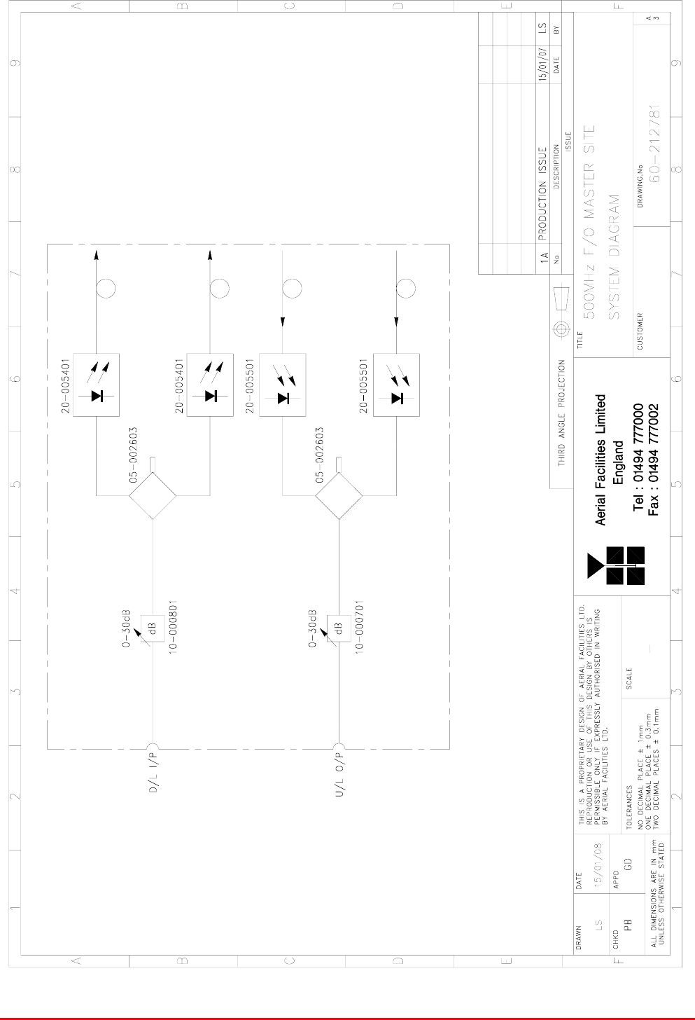
The Master Site Shelf is a 3U Rack mount shelf and provides two separate RF paths, uplink and
downlink with provision to vary the gain of either path using a switched variable attenuator, one in
each path. The active Fibre Optic modules in the unit are powered from an internal 12V PSU which
runs from a mains feed of 110V AC
The downlink signal is received from the antenna and enters the master site via the port labelled “TX”,
the signal passes through a switched variable attenuator (10-000801) providing up to 30dB of
attenuation 2dB steps. After leaving the attenuator the signal is split into two equal paths by a 3dB
splitter/combiner (05-002603) and each path is passed into a Fibre Optic Transmitter (20-005401)
where the signal is modulated onto a laser as an optical signal for transmission to the remote site via
fibre optic cable. The fibre optic signal leaves the master site via the ports labelled “F/O DL” (Fibre
Optic Downlink). Only one “F/O DL” port is used, the second one being available for future expansion.
Uplink signals are received at the master site as optical signals sent from the remote site, the fibre
optic cable carrying the optical signals enter the master site via the ports labelled “F/O UL” (Only one
“F/O UL” port is used, the second one being available for future expansion). Upon entering the master
site the optical signal is passed to a fibre optic receiver (20-005501) where the signal is demodulated
into an RF signal. After leaving the fibre optic receivers the two RF signal paths are combined by a
3dB splitter/combiner (05-002603) to produce a single path which then passes through a switched
variable attenuator (10-000701) providing up to 30dB of attenuation 2dB steps. After leaving the
attenuator the RF signal leaves the master site via the port labelled “RX”
3.1. 60-212701 Parts List (Major Components)
Component
Part
Component Part Description Qty Per
Assembly
05-002603 UHF 3dB Splitter/Combiner 2
10-000701 Switched Attenuator 0-30dB 0.25W 1
10-000801 Switched Attenuator 0-30dB 1W 1
20-005401 Fibre Optic Transmitter (2.7GHz) 1
20-005501 Fibre Optic Receiver (2.7GHz) 1
80-008901 12V Relay Assembly 1
96-300048 PSU 50W (12V 5A) 1
96-920022 Circuit Breaker (3A) 1
The individual fibre optic TX and RX units are fitted with a pair of status indicators on their front
panels. One is a green LED, which indicates that the unit is connected to a 12 Volt DC power supply.
This indicator is common to both transmit and receive units. The second LED on the TX module
indicates that the laser is operating (transmitting). On the RX unit the second LED indicates that a
laser-light signal is being received.
When all the fibre connections are completed and power to each site is connected each fibre unit
must show two illuminated indicators.
Fibre Optic Master and Remote Site
User Handbook
Document Number: 60-212701HBK - Issue No. 1 Page 9 of 50
3.2. 60-212701 Diagrams
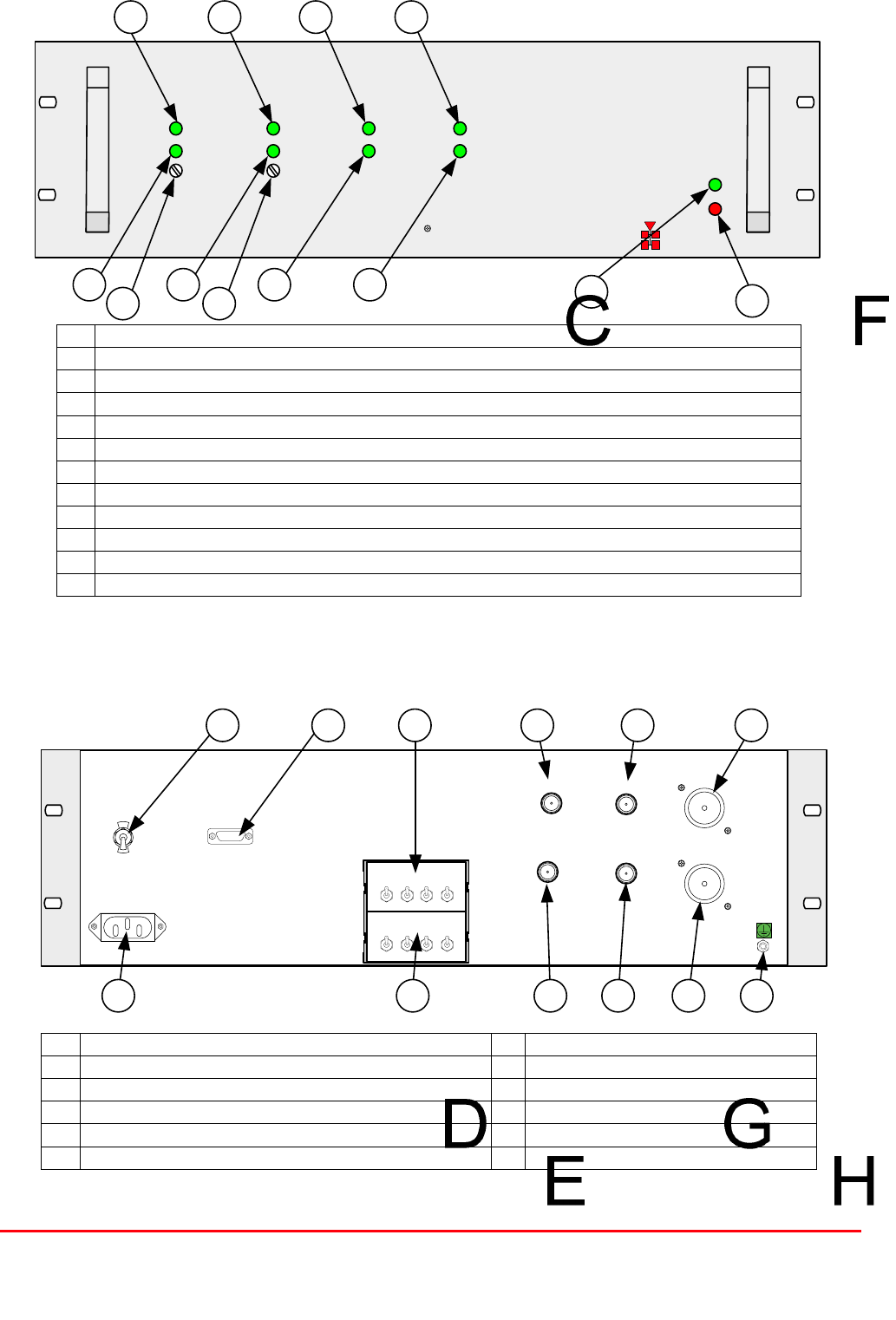
Master Site 60-212701 Front Panel (Not to scale)
A Green LED “Power On”
B Red LED “Alarm”
C Green LED Fibre Optic Receiver 1 “Power On”
D Green LED Fibre Optic Receiver 1 “Laser On”, LED not illuminated = Alarm
E Fibre Optic Receiver 1 Gain Adjust
F Green LED Fibre Optic Receiver 2 “Power On”
G Green LED Fibre Optic Receiver 2 “Laser On”, LED not illuminated = Alarm
H Fibre Optic Receiver 2 Gain Adjust
I Green LED Fibre Optic Transmitter 1 “Power On”
J Green LED Fibre Optic Transmitter 1 “Laser On”, LED not illuminated = Alarm
K Green LED Fibre Optic Transmitter 2 “Power On”
L Green LED Fibre Optic Transmitter 2 “Laser On”, LED not illuminated = Alarm
Master Site 60-212701 Rear Panel (Not to scale)
A RX Port – Uplink RF out to antenna G Earth connection
B Fibre Optic input 2 (uplink from remote site) H Uplink Switched Attenuator
C Fibre Optic input 1 (uplink from remote site) I Downlink Switched Attenuator
D TX Port – Downlink RF in from antenna J Alarm Output
E Fibre Optic output 2 (downlink to remote site) K AC Trip Switch
F Fibre Optic output 1 (downlink to remote site) L AC input (110V)
Fibre Optic Master and Remote Site
User Handbook
Document Number: 60-212701HBK - Issue No. 1 Page 10 of 50
3.3. 60-212701 System Diagram

Fibre Optic Master and Remote Site
User Handbook
Document Number: 60-212701HBK - Issue No. 1 Page 11 of 50
3.4. 60-212701 Major Sub Components
3.4.1. UHF 3dB Splitter/Combiner (05-002603)
The 3dB Splitter/Combiner (05-002603) is a device for accurately matching two RF signals to a single
port or splitting an RF signal to two ports whilst maintaining an accurate 50 load to all inputs/outputs
and ensuring that the VSWR and insertion losses are kept to a minimum.
05-002603 Specification
PARAMETER SPECIFICATION
Frequency range 380 - 520 MHz
Bandwidth 140 MHz
As Combiner 2 inputs 1 output
Ports As Splitter 1 input 2 outputs
Insertion loss 3.5 dB (typical)
Isolation >18 dB
Return Loss (VSWR) – Input Better than 1.3:1
Return Loss (VSWR) – Output Better than 1.3:1
Impedance 50 9
Power Rating – Combiner 0.5 Watt
Power Rating – Splitter 20 Watts
Connectors SMA female
Size 54 x 44 x 21 mm
Weight 200 gm (approximately)
3.4.2. Switched Attenuator 0-30dB 0.25W (10-000701)
10-000701 provides attenuation from 0 - 30dB in 2 dB steps, the attenuation is simply set using the
four miniature toggle switches on the top of each unit. Each switch is clearly marked with the
attenuation it provides, and the total attenuation in line is the sum of the values switched in. They are
designed to maintain an accurate 50 impedance over their operating frequency at both input and
output.
10-000701 Specification
PARAMETER SPECIFICATION
Attenuation Values 0-30dB
Attenuation Steps 2, 4, 8 and 16dB
Power Handling 0.25 Watt
Attenuation Accuracy ± 1.0 dB
Frequency Rang DC to 1GHz
Impedance 50ȍ
Connectors SMA
VSWR 1.3:1
Weigh 0.2kg
operation -20°C to +60°C Temperature
range storage -40°C to +70°C

Fibre Optic Master and Remote Site
User Handbook
Document Number: 60-212701HBK - Issue No. 1 Page 12 of 50
3.4.3. Switched Attenuator 0-30dB 1W (10-000801)
10-000801 provides attenuation from 0 - 30dB in 2 dB steps, the attenuation is simply set using the
four miniature toggle switches on the top of each unit. Each switch is clearly marked with the
attenuation it provides, and the total attenuation in line is the sum of the values switched in. They are
designed to maintain an accurate 50ȍ impedance over their operating frequency at both input and
output.
10-000801 Specification
PARAMETER SPECIFICATION
Attenuation Values 0-30dB
Attenuation Steps 2, 4, 8 and 16dB
Power Handling 1 Watt
Attenuation Accuracy ± 1.0 dB
Frequency Rang DC to 1GHz
Impedance 50ȍ
Connectors SMA
VSWR 1.3:1
Weigh 0.2kg
operation -20°C to +60°C Temperature
range storage -40°C to +70°C
3.4.4. Fibre Optic Transmitter (2.7GHz) (20-005401)
The transmitter modulates the RF signal on to a laser, which is then transmitted over a fibre optic
cable to a receiver. The laser current is monitored and compensated for constant optical out put
power against temperature variation and aging. Laser over-current alarm function is provided as LED
output as well as open collect and voltage-free relay contacts on 9 way D-type connector.
20-005401 specification
PARAMETER SPECIFICATION
Frequency Range (RF path) 70 - 3000 MHz
Frequency Range (Data path) 20 – 35 MHz
Available Link Gain (RF Path) 18 dB
Link Gain ( DATA Path) 0 dB
Gain Flatness (entire frequency range) ±1.5 dB p-p
'Gain vs. Temperature -20 to 70 ºC 3.5 dB
Gain adjustment range ( RF Path ) 30 dB
In/Out Return Loss (RF path) 10 dB Min
Output IP3 @ max gain * 37 dBm
In/Output IP3 @ 0dB Gain * 33 dBm
RF impedance 50 Ohm
Noise Figure @ 0dB gain (400MHz) 36 dB
Optical Transmit Power 2.7±0.3 dBm
Optical return loss >50 dB
Received Power Alarm Threshold -10 dBm(optic)
Optical wavelength 1310 nm
DC Supply Voltage 10-12 Vdc
DC Supply Current 120 mA
Operating Temperature -20 to 70 ºC
Storage Temperature -30 to 85 ºC
RF Connector type SMA
Fibre optic connector type FC/APC
Fibre Optic Master and Remote Site
User Handbook
Document Number: 60-212701HBK - Issue No. 1 Page 13 of 50
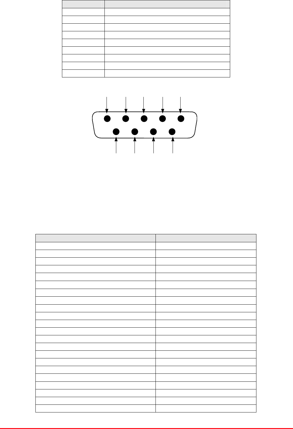
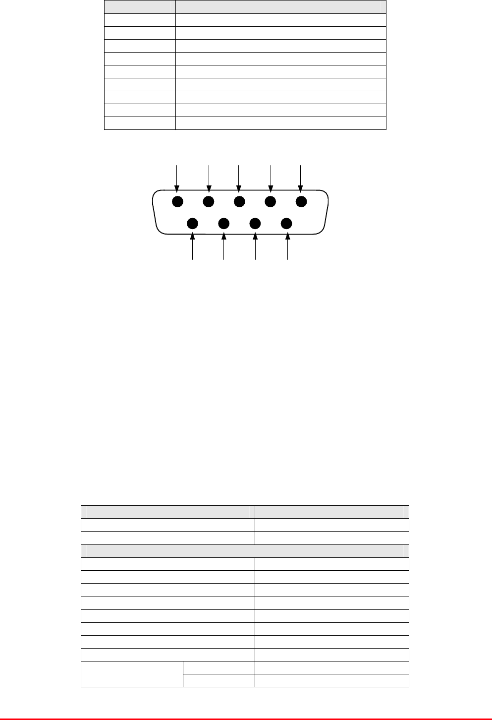
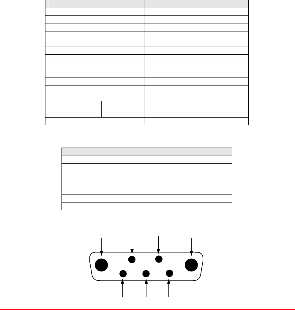
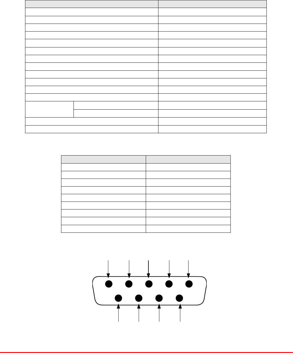
Fibre Optic Transmitter (20-005401) ‘D’ Type Female Connector Pinouts
Pin No. Signal Description
1 +10-12V DC Power
2 0V DC, Power Ground
3 0V DC, Power Ground
4 No Connection
5 No Connection
6 TTL Alarm, (0V=good, open coll.= fail)
7 Relay Alarm Contact (N.C)
8 Relay Alarm Contact (Common)
9 Relay Alarm Contact (N.O)
3.4.5. Fibre Optic Receiver (2.7GHz) (20-005501)
The receiver demodulates RF signals from the laser with a typical gain of 18dB and with 30dB
adjustability in the RF domain. The received optical power is monitored for alarm function in case of
fibre damage.
20-005501 Specification
PARAMETER SPECIFICATION
Frequency Range (RF path) 70 - 3000 MHz
Frequency Range (Data path) 20 – 35 MHz
Available Link Gain (RF Path) 18 dB
Link Gain ( DATA Path) 0 dB
Gain Flatness (entire frequency range) ±1.5 dB p-p
'Gain vs. Temperature -20 to 70 ºC 3.5 dB
Gain adjustment range ( RF Path ) 30 dB
In/Out Return Loss (RF path) 10 dB Min
Output IP3 @ max Gain 37 dBm
In/Output IP3 @ 0dB Gain 33 dBm
RF impedance 50 Ohm
Noise Figure @ 0dB gain (400MHz) 36 dB
Optical Transmit Power 2.7±0.3 dBm
Optical return loss >50 dB
Received Power Alarm Threshold -10 dBm(optic)
Optical wavelength 1310 nm
DC Supply Voltage 10-12 Vdc
DC Supply Current 350 mA
Operating Temperature -20 to 70 ºC
Storage Temperature -30 to 85 ºC
RF Connector type SMA
Fibre optic connector type FC/APC
Fibre Optic Master and Remote Site
User Handbook
Document Number: 60-212701HBK - Issue No. 1 Page 14 of 50
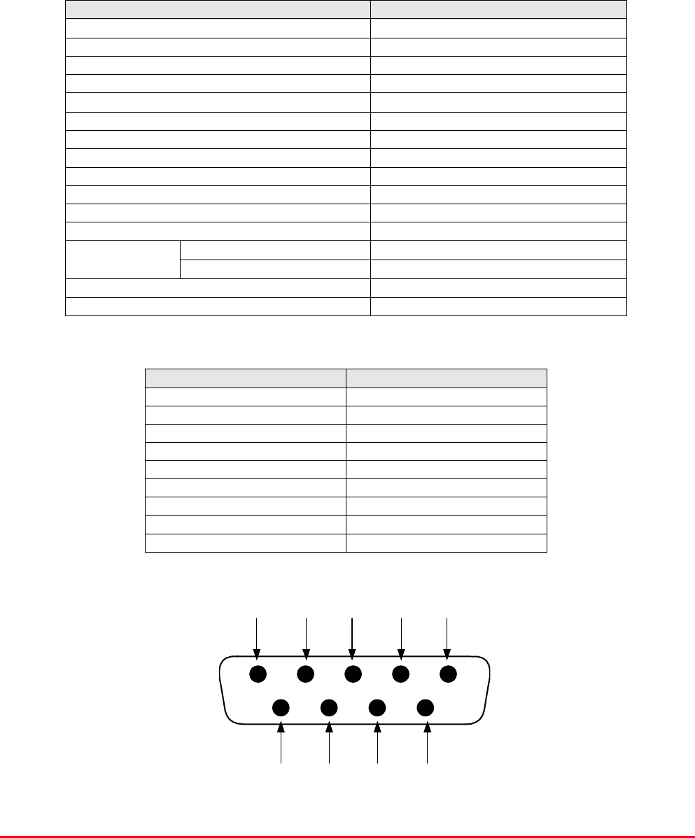
Fibre Optic Receiver (20-005501) ‘D’ Type Female Connector Pinouts
Pin No. Signal Description
1 +10-12V DC Power
2 0V DC, Power Ground
3 0V DC, Power Ground
4 No Connection
5 No Connection
6 TTL Alarm, (0V=good, open coll.= fail)
7 Relay Alarm Contact (N.C)
8 Relay Alarm Contact (Common)
9 Relay Alarm Contact (N.O)
3.4.6. 12V Relay Assembly (80-008901)
The General Purpose Relay Board allows the inversion of signals and the isolation of circuits. It is
equipped with a single dual pole change-over relay RL1, with completely isolated wiring, accessed
via a 15 way in-line connector.
The relay is provided with polarity protection diodes and diodes for suppressing the transients caused
by "flywheel effect" which can destroy switching transistors or induce spikes on neighbouring circuits.
Its common use is to amalgamate all the alarm signals into one, volts-free relay contact pair for the
main alarm system.
80-008901 Specification
PARAMETER SPECIFICATION
Operating voltage 8 to 30V (floating earth)
Alarm threshold Vcc - 1.20 volt +15%
Alarm output relay contacts
Max. switch current 1.0Amp
Max. switch volts 120Vdc/60VA
Max. switch power 24W/60VA
Min. switch load 10.0µA/10.0mV
Relay isolation 1.5kV
Mechanical life >2x10⁷ operations
Relay approval BT type 56
Connector details Screw terminals
operational -10°C to +60°C Temperature
range storage -20°C to +70°C

Fibre Optic Master and Remote Site
User Handbook
Document Number: 60-212701HBK - Issue No. 1 Page 15 of 50
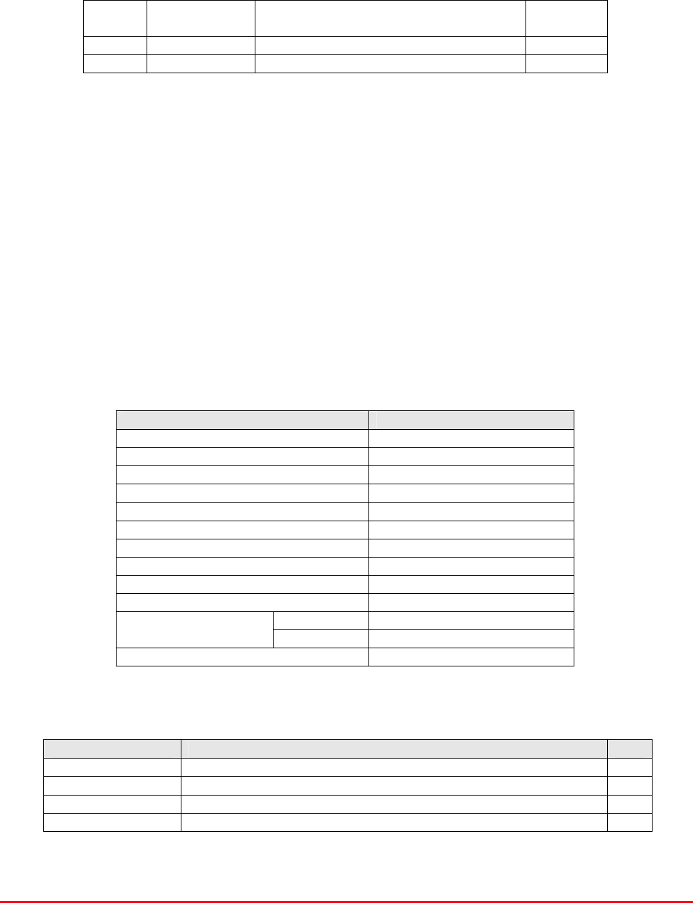
3.4.7. PSU 50W (12V 5A) (96-300048)
The power supply unit is a switched-mode type capable of supplying 12V DC at 5Amps continuously.
No routine maintenance of the PSU is required. If a fault is suspected, then the output voltage from
the power supply may be measured on its output terminals. This is typically set to 12.2V. The
adjustment potentiometer will be found close to the DC output terminals.
All the PSUs used in AFL Cell Enhancers are capable of operation from either 110 or 220V nominal
AC supplies. The line voltage is sensed automatically, so no adjustment or link setting is needed by
the operator.
96-300048 Specification
AC Input Supply
110 or 220V nominal
Voltage: 90 to 132 or 180 to 264V
(absolute limits)
Frequency: 47 to 63Hz
DC Output Supply
12V DC (nominal)
Voltage: 10.5-13.8V (absolute limits)
Current: 5.0A
Fibre Optic Master and Remote Site
User Handbook
Document Number: 60-212701HBK - Issue No. 1 Page 16 of 50
4. REMOTE SITE 60-212801
The Remote Site 60-212801 is composed of two rack mount chassis, one containing the filtering, and
amplification modules along with the fibre optic transmitter and receiver (60-212802), the second tray
is a 100 W amplifier (80-245101), part of the Downlink signal path.
60-212801 sub components
section Component
Part
Component Part Description Qty Per
Assembly
4.1. 80-245101 100W Linearised Amplifier 1
4.2. 60-212802 Remote Uplink/Downlink Tray 1
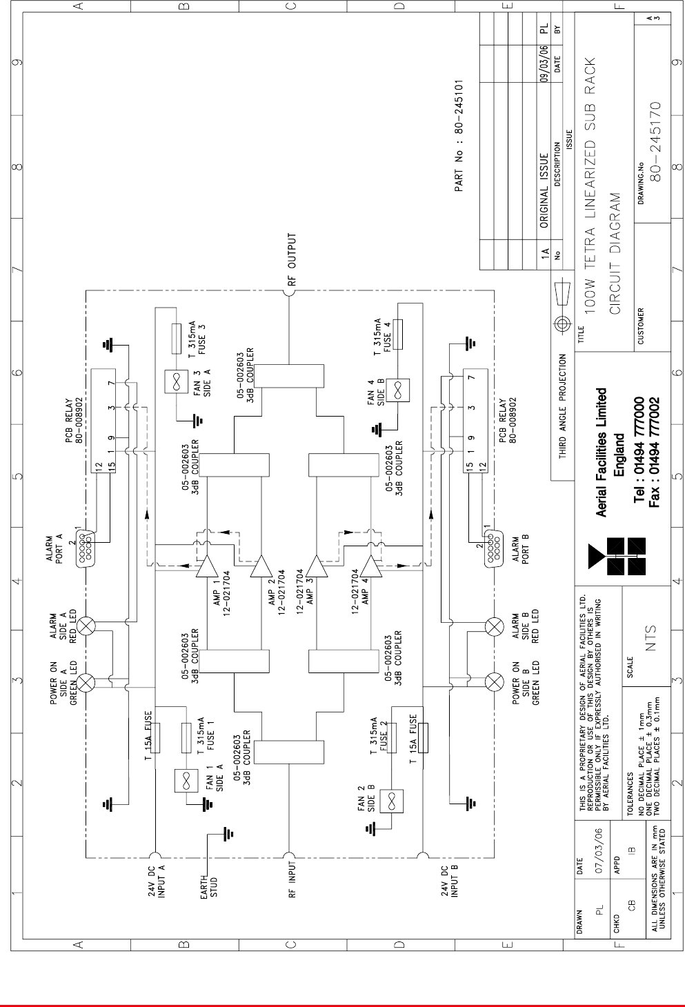
4.1. 100W Linearised Amplifier (80-245101)
100W Linearised Amplifier (80-245101) shelf is a Class A 100W TETRA Linearised Class A amplifier
where 4 linearised power amplifiers are combined together in a ‘phased-parallel’ arrangement. Its
housing is a 4U 19” Rack-mount shelf with SMA connectors for the RF input/output, 2 D-Type
connectors for the alarm function and 2 DC connectors with fuses for the 24 DC supplies. Cooling is
effected by fans mounted on the front panel.
It has a built in Current Fault Alarm Function with the four amplifiers in two summary alarm paths. The
summary alarm on ‘D’ connector ‘A’ will show an alarm for the two amplifiers mounted on the top of
the shelf (amplifier pair “A”). The summary alarm on ‘D’ connector ‘B’ will show an alarm for the two
amplifiers mounted at the bottom of the shelf (amplifier pair “B”)
4.1.1. 80-245101 Specification
PARAMETER SPECIFICATION
Frequency range: 440-500MHz
Small signal gain: 37dB
Gain flatness: ±0.5dB
I/O Return loss: >18dB
1dB compression point: +50dBm
OIP3: +69dBm
Supply voltage: 24V DC (x2)
Supply current: 18-19Amps
Impedance: 50ȍ
Environmental protection rating: IP44
operational: -10°C to +60°C
Temperature range storage: -40°C to +70°C
Weight: <5kg
4.1.2. 80-245101 Parts List (Major Components)
AFL Part No. Part Description Qty.
05-002603 UHF 3dB Splitter/Combiner 6
12-026902 25W Linearised Amplifier Module 4
80-008902 24V Relay PCB Assembly 2
96-400002 Cooling Fan 4
Fibre Optic Master and Remote Site
User Handbook
Document Number: 60-212701HBK - Issue No. 1 Page 17 of 50
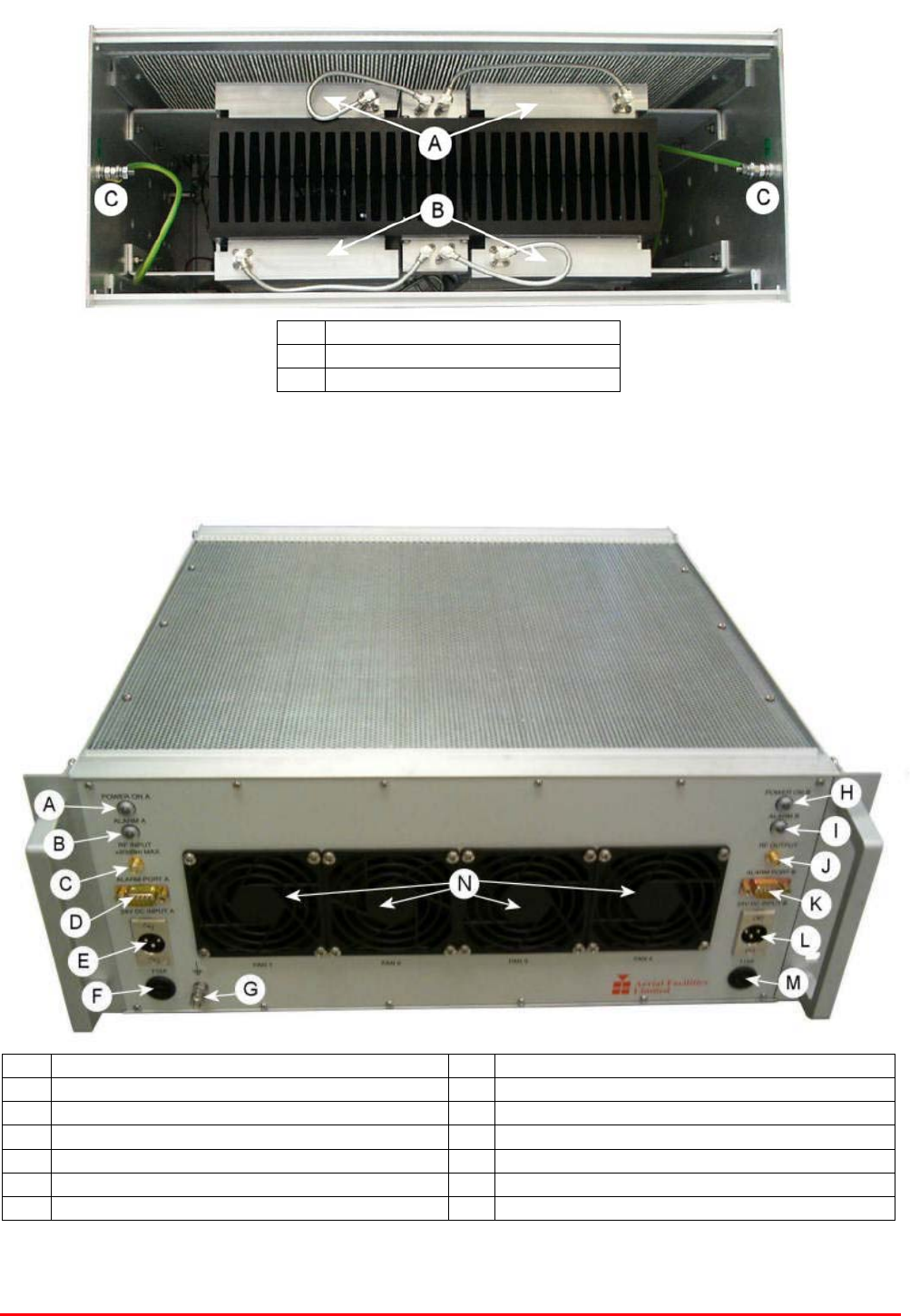
4.1.3. 80-245101 Photographs
100W Linearised Amplifier (80-245101) rear view
A Amplifier pair “A”
B Amplifier pair “B”
C Earthing connections
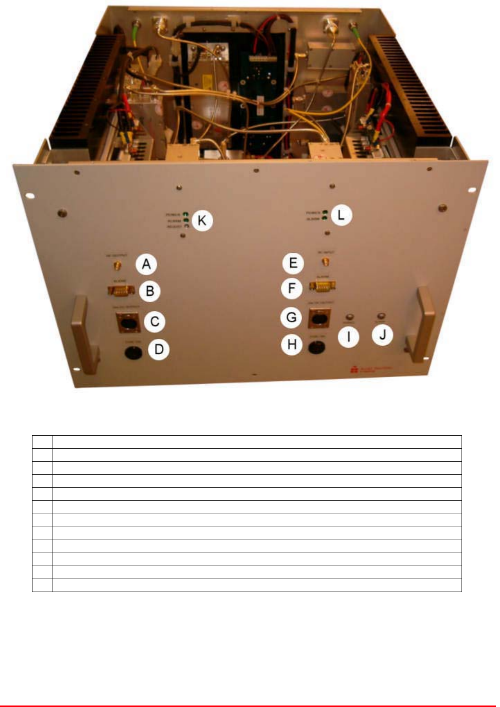
100W Linearised Amplifier (80-245101) front view
A Green LED “Power On” Amplifier pair “A” H Green LED “Power On” Amplifier pair “B”
B Red LED “Alarm” Amplifier pair “A” I Red LED “Alarm” Amplifier pair “B”
C RF input from 60-212802 J RF output to 60-212802
D Alarm output Amplifier pair “A” K Alarm output Amplifier pair “B”
E DC input Amplifier pair “A” L DC input Amplifier pair “B”
F Fuse holder Amplifier pair “A” M Fuse holder Amplifier pair “B”
G Earth connection for 80-245101 N Cooling fans
Fibre Optic Master and Remote Site
User Handbook
Document Number: 60-212701HBK - Issue No. 1 Page 18 of 50
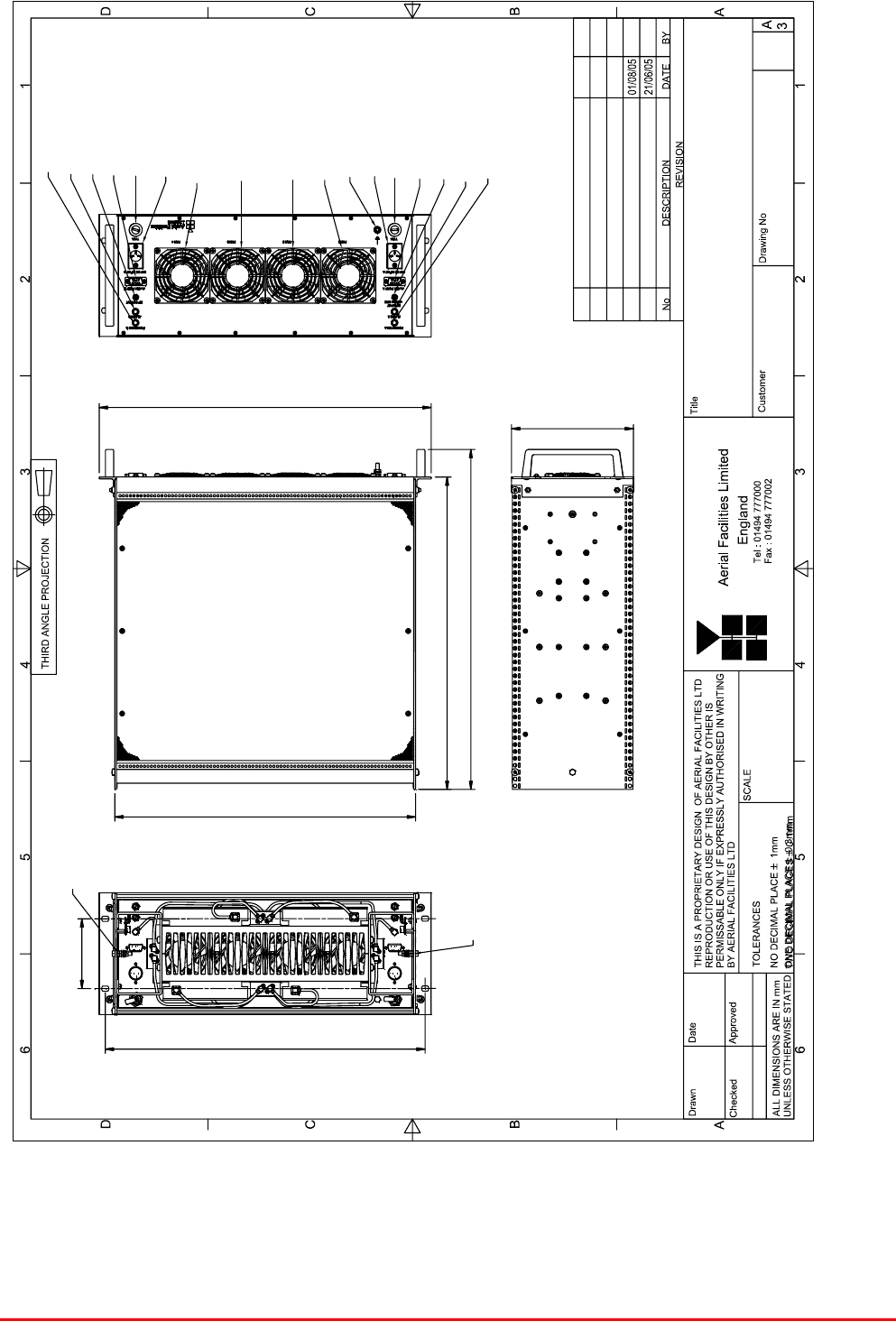
100W TETRA CLASS A LINEARIZED AMPLIFIER RACK
21/06/05
80-245190
CB
14/09/2005
IB
14/09/2005
1A
1:4
OUTLINE DRAWING
PL
101.50
464.50
494.00
454.00
436.80
482.00
177.00
POWER ON B
ALARM B
RF OUTPUT
ALARM PORT B
15A FUSE
24V DC INPUT B
24V DC INPUT A
15A FUSE
ALARM PORT
A
RF INPUT
ALARM
A
POWER ON A
FAN 1
FAN 2
FAN 3
FAN 4
EARTH STUD
EARTH STUD
PART No 80-245101 AA ORIGINAL ISSUE PL
MATERIAL : ALUMINIUM ALLOY
CONNECTORS : SMA SOCKET
3 PIN PLUG (NC-X)
9 WAY 'D' TYPE PLUG
1A ECN3733 PL
EARTH STUD
4.1.4. 80-245101 Outline Drawing
Fibre Optic Master and Remote Site
User Handbook
Document Number: 60-212701HBK - Issue No. 1 Page 19 of 50
4.1.5. 80-245101 System Diagram
Fibre Optic Master and Remote Site
User Handbook
Document Number: 60-212701HBK - Issue No. 1 Page 20 of 50
4.1.6. 80-245101 Major Sub Components
4.1.6.1. 25W Linearised Amplifier Module (12-026902)
Linearised Power Amplifier (12-026902) is a multi-stage, solid state power amplifier. Class A circuitry
is employed throughout the device to ensure excellent linearity over a wide dynamic frequency range.
All the semi-conductor devices are very conservatively rated to ensure low device junction
temperatures and a long, trouble free working lifetime.
The power amplifier should require no maintenance over its operating life. Under no circumstances
should the cover be removed or the side adjustments disturbed unless it is certain that the amplifier
has failed; since it is critically aligned during manufacture and any re-alignment will require extensive
test equipment. The module housing is an aluminium case (Iridite NCP finish) with SMA connectors
for the RF input/output and a D-Type connector for the power supply and the Current Fault Alarm
Function.
12-026902 Specification
PARAMETER SPECIFICATION
Frequency range: 440-500MHz (tuned to spec.)
Bandwidth: <60MHz (typical)
Maximum RF output: >25Watt
Small signal gain: 37.5dB (typical)
1dB compression point: +44dBm
3rd order intercept point: +61dBm
Noise figure: N/A
Return input loss: >15dB
Return output loss: >15dB
VSWR: better than 1.5:1
Connectors: SMA female
Supply: 4.6Amps @ 24V DC
operation: -10qC to +60qC
Temperature
range: storage: -20qC to +70qC
Weight: 1.5 kg
PA 7-Way Connector Pin-outs
Connector Pin Signal
A1 (large pin) +24V DC
A2 (large pin) GND
1 Alarm relay common
2 TTL alarm/0V good
3 Alarm relay contact (bad)
4 Alarm relay contact (good)
5 O/C good/0V bad (TTL)

Fibre Optic Master and Remote Site
User Handbook
Document Number: 60-212701HBK - Issue No. 1 Page 21 of 50
4.1.6.2. UHF 3dB Splitter/Combiner (05-002603)
The 3dB Splitter/Combiner (05-002603) is a device for accurately matching two RF signals to a single
port or splitting an RF signal to two ports whilst maintaining an accurate 50 load to all inputs/outputs
and ensuring that the VSWR and insertion losses are kept to a minimum.
05-002603 Specification
PARAMETER SPECIFICATION
Frequency range 380 - 520 MHz
Bandwidth 140 MHz
As Combiner 2 inputs 1 output
Ports As Splitter 1 input 2 outputs
Insertion loss 3.5 dB (typical)
Isolation >18 dB
Return Loss (VSWR) – Input Better than 1.3:1
Return Loss (VSWR) – Output Better than 1.3:1
Impedance 50 9
Power Rating – Combiner 0.5 Watt
Power Rating – Splitter 20 Watts
Connectors SMA female
Size 54 x 44 x 21 mm
Weight 200 gm (approximately)
4.1.6.3. 24V Relay PCB Assembly (80-008902)
The General Purpose Relay Board allows the inversion of signals and the isolation of circuits. It is
equipped with a single, dual pole, change-over relay RL1 with completely isolated wiring, accessed
via screw terminals.
The relay is provided with a polarity protection diode and diodes for suppressing the transients
caused by "flywheel effect" which can destroy switching transistors or induce spikes on neighbouring
circuits. Its common use is to amalgamate all the alarm signals into one, volts-free relay contact pair
for the main alarm system.
80-008902 Technical Specification
Parameter Specification
Max. switch current 1.0Amp
Max. switch volts 120Vdc/60VA
Max. switch power 24W/60VA
Min. switch load 10.0µA/10.0mV
Relay isolation 1.5kV
Mechanical life >2x10⁷ operations
Relay approval BT type 56
Connector details 15-way 0.1" pitch
operational -10°C to +55°C Temperature
range storage -40°C to +70°C

Fibre Optic Master and Remote Site
User Handbook
Document Number: 60-212701HBK - Issue No. 1 Page 22 of 50
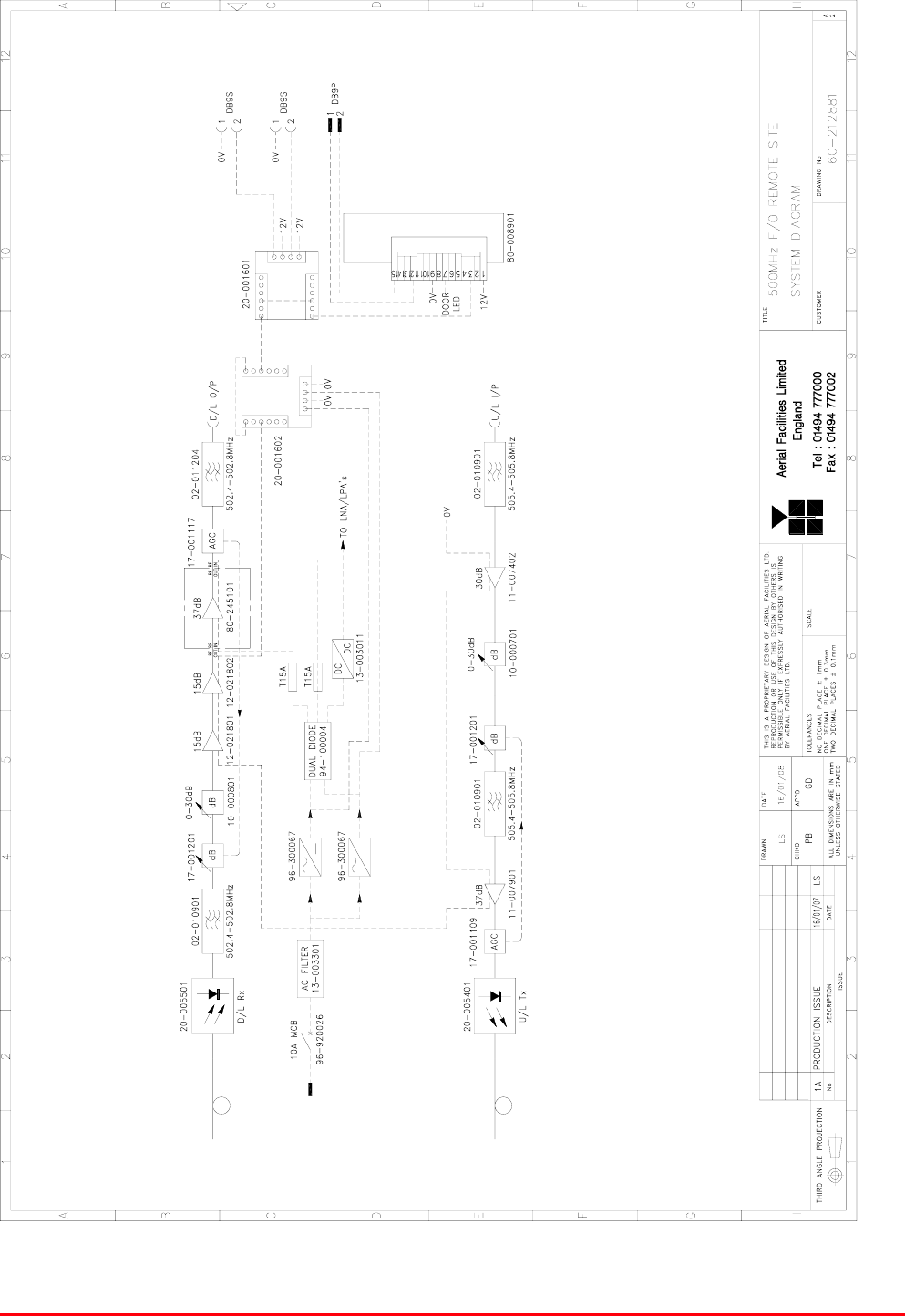
4.2. Remote Uplink/Downlink Shelf (60-212802)
The Remote Uplink/Downlink Shelf is an 8U Rack mount shelf and provides two separate RF paths,
uplink and downlink with provision to vary the gain of either path using a switched variable (0 to 30dB)
attenuator, one in each path. Each path is also fitted with an Automatic Gain Control (AGC) circuit
which consists of two units, a detector/amplifier and an attenuator. Normally the attenuators in the
AGC circuit are at minimum attenuation. The detector/amplifier unit monitors the RF level being
delivered by the power amplifier, and when a certain threshold is reached it begins to increase the
value of the attenuator to limit the RF output to the (factory set) threshold; therefore overloading of the
amplifiers is avoided.
The downlink signal is received from the master site as an optical signal which is demodulated into an
RF signal. The RF signal is then passed through a bandpass filter (tuned to pass the downlink
bandwidth 502.4MHz to 502.8MHz) to reject out-of-band noise and then passes through the downlink
AGC attenuator and into the Downlink Switched Attenuator. From the Switched Attenuator the
Downlink signal passes through two low power amplifiers (1W, 15dB gain and 2W, 15dB gain) and
then exits 60-212802 to go to the 100W Linearised Amplifier (80-245101). After leaving 60-212802
the downlink signal re-enters 60-212802, passing through the downlink AGC detector and a second
bandpass filter before exiting the shelf via the D/L Output port
The uplink RF path enters 60-212802 at the U/L Input port and the signal passes through a bandpass
filter (tuned to pass the uplink bandwidth 505.4MHz to 505.8MHz) to reject out-of-band noise. After
the bandpass filter the signal passes through a 30dB Low Noise Amplifier and then into the uplink
Switched Attenuator followed by the uplink AGC attenuator. After the AGC attenuator the signal
passes through a second bandpass filter and then through a low power amplifier (1W, 37dB gain)
followed by the uplink AGC detector. From the AGC detector the uplink signal passes into a fibre optic
transmitter where the RF signal is modulated into an optical signal for transmission via fibre optic
cable to the master site.
All the amplifier modules in this shelf are alarmed and the summary terminates at the rear panel
mounted 9-way ‘D’ alarm connector.
4.2.1. 60-212802 Parts List (Major Components)
Component
Part
Component Part Description Qty Per
Assembly
02-010901 Bandpass Filter 3
02-011204 Bandpass Filter 1
10-000701 Switched Attenuator 0-30dB 0.25W 1
10-000801 Switched Attenuator 0-30dB 1W 1
11-007402 Low Noise Amplifier 1
11-007901 Low Power Amplifier (1W) 1
12-021801 Low Power Amplifier (1W) 1
12-021802 Low Power Amplifier (2W) 1
13-003011 DC-DC Converter 24V -12V 1
13-003301 Mains Filter (8 Amp) 1
17-001109 AGC Logarithmic Detector /Amplifier 1
17-001117 AGC Detector /Amplifier 1
17-001201 AGC Attenuator 2
20-001601 12V Relay Board 1
20-001602 24V Relay Board 1
20-005401 Fibre Optic Transmitter (2.7GHz) 1
20-005501 Fibre Optic Receiver (2.7GHz) 1
80-008901 12V Relay Assembly 1
93-510077 0R02 50W Resistor Aluminium Clad 2
94-100004 60A Dual Diode 1
96-300067 PSU 600W (24V 23A) 2
96-920026 Circuit Breaker 10A 1
Fibre Optic Master and Remote Site
User Handbook
Document Number: 60-212701HBK - Issue No. 1 Page 23 of 50
4.2.2. 60-212802 Photographs
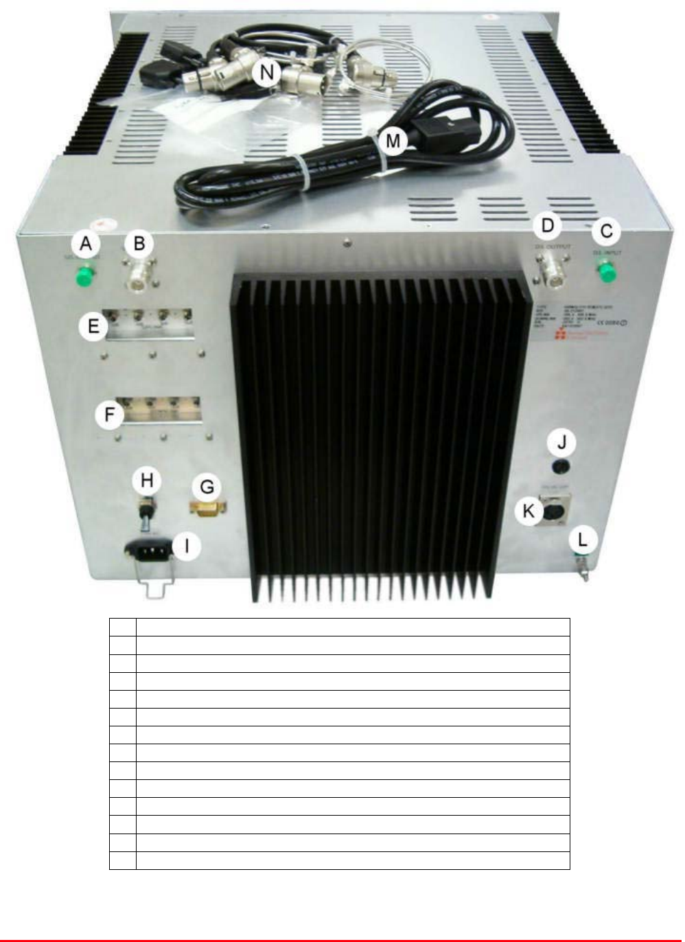
Remote Uplink/Downlink Tray (60-212802) front view
A RF output to 100W Linearised Amplifier 80-245101
B Alarm input from amplifier pair “A” in 80-245101
C DC output to amplifier pair “A” in 80-245101
D Fuse on DC output to amplifier pair “A” in 80-245101
E RF input from 100W Linearised Amplifier 80-245101
F Alarm input from amplifier pair “B” in 80-245101
G DC output to amplifier pair “B” in 80-245101
H Fuse on DC output to amplifier pair “B” in 80-245101
I Green LED “Power On”
J Red LED “Alarm”
K Power On LED, Alarm LED and Gain Adjust for Fibre Optic Receiver 20-005501
L Power On LED and Alarm LED for Fibre Optic Transmitter 20-005401
Fibre Optic Master and Remote Site
User Handbook
Document Number: 60-212701HBK - Issue No. 1 Page 24 of 50
Remote Uplink/Downlink Tray (60-212802) rear view
A Uplink Fibre Optic output to Master site
B Uplink RF input from mobile antenna
C Downlink Fibre Optic input from Master site
D Downlink RF output to mobile antenna
E Uplink switched attenuator 10-000701
F Downlink switched attenuator 10-000801
G Alarm Output
H AC Trip switch
I AC Input (110V )
J DC Fuse
K 12V DC Auxiliary Output
L Earth connection
M AC power cord
N DC, RF and Alarm interconnections for Amplifier 80-245101
Fibre Optic Master and Remote Site
User Handbook
Document Number: 60-212701HBK - Issue No. 1 Page 25 of 50
4.2.3. Remote Site 60-212801 System Diagram

Fibre Optic Master and Remote Site
User Handbook
Document Number: 60-212701HBK - Issue No. 1 Page 26 of 50
4.2.4. 60-212802 Major Sub Components
4.2.4.1. Bandpass Filter (02-010901)
Bandpass Filter (02-010901) is a multi-section design with a bandwidth dependent upon the
passband frequencies, (both tuned to customer requirements). The response shape is basically
Chebyshev with a passband design ripple of 0.1dB. The filters are of helical & combline design
respectively, and are carefully aligned during manufacture in order to optimise the insertion loss,
VSWR and intermodulation characteristics of the unit. The body and tuned elements are silver-plated
to reduce surface ohmic losses and maintain a good VSWR figure and 50ȍ load at the input and
output ports.
Being passive devices, the bandpass filters should have an extremely long operational life and require
no maintenance.
02-010901 specification
SPECIFICATION PARAMETER
Uplink 505.4 to 505.8MHz ** Passband Frequency
Downlink 502.4 to 502.8MHz **
Uplink 400kHz ** Bandwidth
Downlink 400kHz **
Insertion Loss 1.2 dB (typical)
Power Rating 50W
Impedance 50ȍ
VSWR Better than 1.2:1
Connectors SMA
Weight 3Kg (approximately)
**as tuned for use in 60-212802 uplink and downlink paths
4.2.4.2. Bandpass Filter (02-011204)
Bandpass Filter 02-011204 is a multi-section designs with a bandwidth dependent upon the passband
frequencies, (both tuned to customer requirements). The response shape is basically Chebyshev with
a passband design ripple of 0.1dB. The filters are of combline design, and are carefully aligned during
manufacture in order to optimise the insertion loss, VSWR and intermodulation characteristics of the
unit. The cases and tuned elements are silver-plated to reduce surface ohmic losses and maintain a
good VSWR figure and 50ȍ load at the input and output ports.
Being passive devices, the bandpass filters should have an extremely long operational life and require
no maintenance. Should a filter be suspect, it is usually most time efficient to replace the module
rather than attempt repair or re-tuning. No adjustments should be attempted without full network
sweep analysis facilities to monitor both insertion loss and VSWR simultaneously.
02-011204 Specification
Passband Frequency 502.4 to 502.8MHz **
Bandwidth 400kHz **
Insertion Loss <1.0dB
Power Rating 100W
Impedance 50ȍ
VSWR 1.2:1 (typical)
Connectors SMA
Weight 3Kg (approximately)
**as tuned for use in 60-212802 uplink path
Fibre Optic Master and Remote Site
User Handbook
Document Number: 60-212701HBK - Issue No. 1 Page 27 of 50
4.2.4.3. Switched Attenuator 0-30dB 0.25W (10-000701)
10-000701 provides attenuation from 0 - 30dB in 2 dB steps The attenuation is simply set using the
four miniature toggle switches on the top of each unit. Each switch is clearly marked with the
attenuation it provides, and the total attenuation in line is the sum of the values switched in. They are
designed to maintain an accurate 50ȍ impedance over their operating frequency at both input and
output.
10-000701 Specification
PARAMETER SPECIFICATION
Attenuation Values 0-30dB
Attenuation Steps 2, 4, 8 and 16dB
Power Handling 0.25 Watt
Attenuation Accuracy ± 1.0 dB
Frequency Rang DC to 1GHz
Impedance 50ȍ
Connectors SMA
VSWR 1.3:1
Weigh 0.2kg
operation -20°C to +60°C Temperature
range storage -40°C to +70°C
4.2.4.4. Switched Attenuator 0-30dB 1W (10-000801)
10-000801 provides attenuation from 0 - 30dB in 2 dB steps The attenuation is simply set using the
four miniature toggle switches on the top of each unit. Each switch is clearly marked with the
attenuation it provides, and the total attenuation in line is the sum of the values switched in. They are
designed to maintain an accurate 50ȍ impedance over their operating frequency at both input and
output.
10-000801 Specification
PARAMETER SPECIFICATION
Attenuation Values 0-30dB
Attenuation Steps 2, 4, 8 and 16dB
Power Handling 1 Watt
Attenuation Accuracy ± 1.0 dB
Frequency Rang DC to 1GHz
Impedance 50ȍ
Connectors SMA
VSWR 1.3:1
Weigh 0.2kg
operation -20°C to +60°C Temperature
range storage -40°C to +70°C
Fibre Optic Master and Remote Site
User Handbook
Document Number: 60-212701HBK - Issue No. 1 Page 28 of 50
4.2.4.5. Low Noise Amplifier (11-007402)
The 30dB gain low noise amplifier used is a double stage solid-state low-noise amplifier. Class A
circuitry is used in the unit to ensure excellent linearity over a very wide dynamic range. The two
active devices are very moderately rated to provide a long trouble-free working life. There are no
adjustments on this amplifier, and in the unlikely event of failure then the entire amplifier should be
replaced. The amplifier features a dedicated, in-built alarm monitoring system which gives a TTL
‘open collector’ type switched signal on alarm, this is then integrated using a built-in relay to give a
volt-free contact for summation into the main alarm system.
11-007402 Specification
PARAMETER SPECIFICATION
Frequency range 380-500MHz
Bandwidth <140MHz
Gain 30-32dB
1dB Compression point +22dBm (typical)
3rd order intercept +34-35dBm (typical)
Input/Output return loss >20dB
Noise figure <1.3dB
Connectors SMA female
Supply 300-330mA @ 24V DC
operational -20°C to +60°C Temperature
range storage -40°C to +70°C
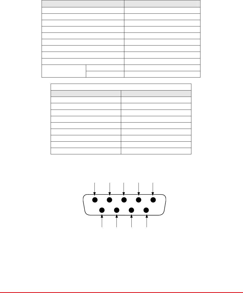
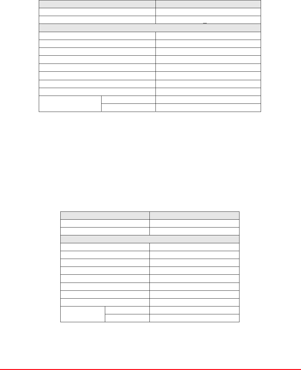
LNA ‘D’ Connector Pin-out details
Connector pin Signal
1 +ve input (10-24V)
2 GND
3 Alarm relay O/P bad
4 Alarm relay common
5 Alarm relay good
6 No connection
7 TTL voltage set
8 TTL alarm/0V (good)
9 O/C good/0V bad
9-Way Pin-Out Graphical Representation
Fibre Optic Master and Remote Site
User Handbook
Document Number: 60-212701HBK - Issue No. 1 Page 29 of 50
4.2.4.6. Low Power Amplifier (1W) (11-007901)
This amplifier is dedicated to be a 1.0 W driver from 380 MHz to 470 MHz. It is a 2 stage amplifier
where each stage is in balanced configuration. It demonstrates very high linearity and good
input/output VSWR. There is a Current Fault Alarm Function, which indicates failure of each one of
the RF transistors by various alarm output options. The amplifier is housed in an aluminium case
(Iridite NCP finish) with SMA connectors for the RF input/output and a 9way D-type connector for DC
and alarm outputs.
11-007901 Specifications
PARAMETER SPECIFICATION
Frequency range: 380-470MHz
Small signal gain: 37.5dB
Gain flatness: ±0.5dB
Gain vs. temperature: 1.5dB
operational: -20qC to +60qC
Temperature range: storage: -40qC to +70qC
Input/output return loss: 18dB
Maximum output power: 30.4dBm (@ 1dB comp. point)
OIP3: 43dBm
Supply voltage: 10-15V DC
Current consumption: 780mA (typical)
Noise Figure: <1.75dB
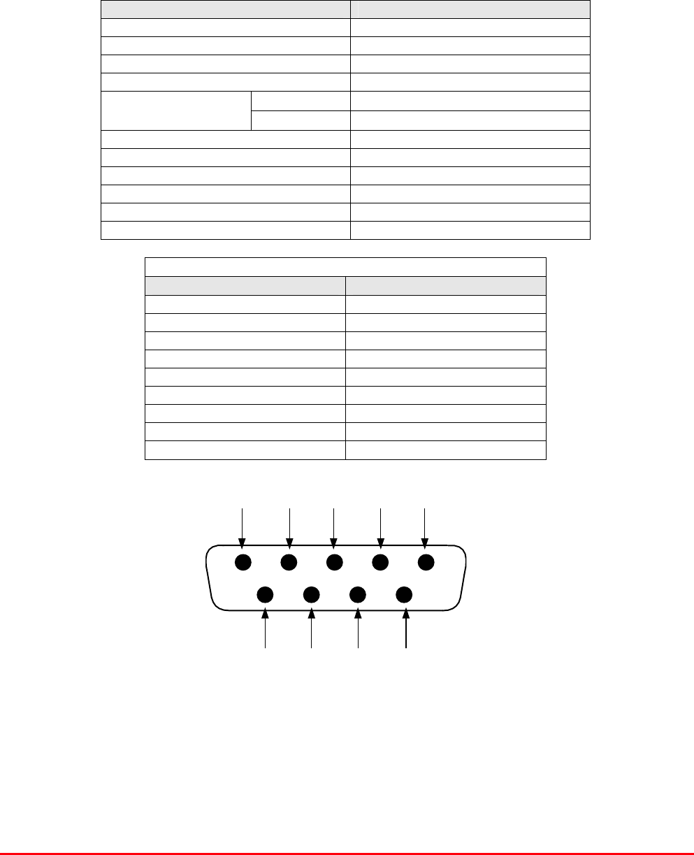
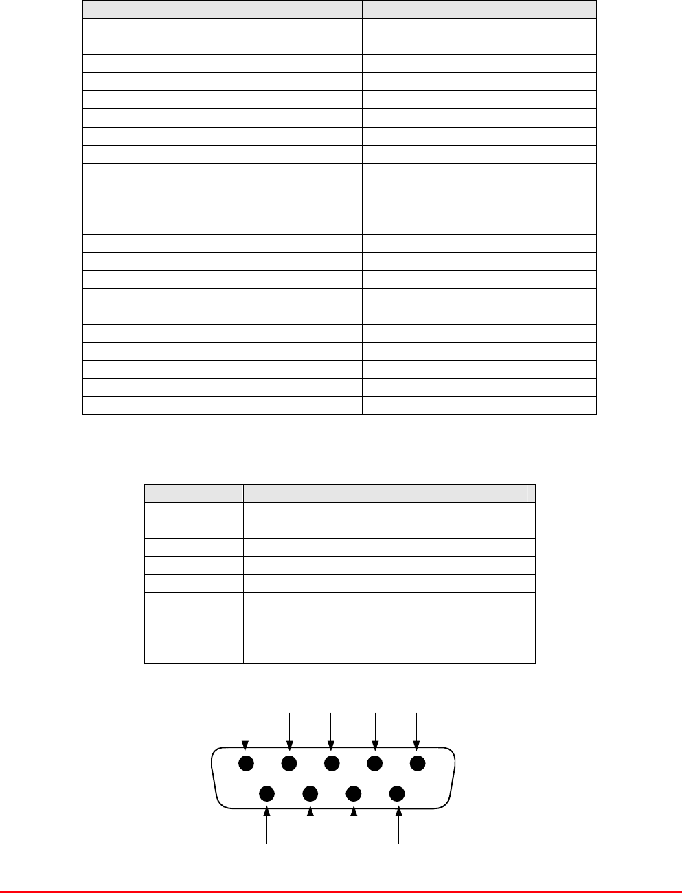
LNA ‘D’ Connector Pin-out details
Connector pin Signal
1 +ve input (10-24V)
2 GND
3 Alarm relay O/P bad
4 Alarm relay common
5 Alarm relay good
6 No connection
7 TTL voltage set
8 TTL alarm/0V (good)
9 O/C good/0V bad
Fibre Optic Master and Remote Site
User Handbook
Document Number: 60-212701HBK - Issue No. 1 Page 30 of 50
7 8 96
1 2 3 4 5
9-Way Pin-Out Graphical Representation
4.2.4.7. Low Power Amplifier (1W) (12-021801)
The low power amplifier used is a 1 stage balanced configuration, solid-state amplifier. Class A
circuitry is used in the unit to ensure excellent linearity over a very wide dynamic range. The three
active devices are very moderately rated to provide a long trouble-free working life.
Its housing is an aluminium case (Iridite NCP finish) with SMA connectors for the RF input/output and
a D-Type connector for the power supply and the Current Fault Alarm Function.
There are no adjustments on this amplifier, and in the unlikely event of failure then the entire amplifier
should be replaced.
12-021801 Specification
PARAMETER SPECIFICATION
Temperature -20 to +70 qC
Frequency Range 380 - 500 MHz
Small Signal Gain 15.5 +/- 0.5 dB
Gain Flatness 0.7 dB p-p Max
'Gain vs. Temperature 0.7 dB Max
In RL 20 dB Min
Out RL 20 dB Min
Output Power @ 1dB Compression Point 30.5 dBm Min
Output 3rd Order IP 41.5 dBm Min
Noise Figure 6 dB Max
DC Supply Voltage 10-15 Vdc
DC Supply Current 540 mA Max
operational: -10qC to +60qC
Temperature
range: storage: -20qC to +70qC
Weight: <0.5 kg
Size: 110.5 x 66mm x 24.6mm
Low Power Amplifier (12-021801) 9-Way Connector Pin-outs
Connector pin Signal
1 +ve input (10-24V)
2 GND
3 Alarm relay O/P bad
4 Alarm relay common
5 Alarm relay good
6 No connection
7 TTL voltage set
8 TTL alarm/0V (good)
9 O/C good/0V bad
Fibre Optic Master and Remote Site
User Handbook
Document Number: 60-212701HBK - Issue No. 1 Page 31 of 50
7 8 96
1 2 3 4 5
9-Way Pin-Out Graphical Representation
4.2.4.8. Low Power Amplifier (2W) (12-021802)
The low power amplifier used is a 1 stage balanced configuration, solid-state amplifier. Class A
circuitry is used in the unit to ensure excellent linearity over a very wide dynamic range. The three
active devices are very moderately rated to provide a long trouble-free working life.
Its housing is an aluminium case (Iridite NCP finish) with SMA connectors for the RF input/output and
a D-Type connector for the power supply and the Current Fault Alarm Function.
There are no adjustments on this amplifier, and in the unlikely event of failure then the entire amplifier
should be replaced.
12-021802 Specification
PARAMETER SPECIFICATION
Temperature -20 to +70 qC
Frequency Range 380 - 500 MHz
Small Signal Gain 15.5 +/- 0.5 dB
Gain Flatness 0.7 dB p-p Max
'Gain vs. Temperature 0.7 dB Max
In RL 20 dB Min
Out RL 20 dB Min
Output Power @ 1dB Compression Point 33 dBm Min
Output 3rd Order IP 46 dBm Min
Noise Figure 6 dB Max
DC Supply Voltage 10-15 Vdc
DC Supply Current 850 mA Max
operational -20qC to +70qC
Temperature
range storage -40qC to +100qC
Weight <0.5 kg
Size 110.5 x 66mm x 24.6mm
Low Power Amplifier (12-021802) 9-Way Connector Pin-outs
Connector pin Signal
1 +ve input (10-24V)
2 GND
3 Alarm relay O/P bad
4 Alarm relay common
5 Alarm relay good
6 No connection
7 TTL voltage set
8 TTL alarm/0V (good)
9 O/C good/0V bad

Fibre Optic Master and Remote Site
User Handbook
Document Number: 60-212701HBK - Issue No. 1 Page 32 of 50
4.2.4.9. DC-DC Converter 24V -12V (13-003011)
The DC/DC converter fitted is an AFL assembled, high power PCB unit with an 8 amp at 12V output
capability. The circuit is basically an O.E.M semiconductor regulator (one side of which has a heatsink
mounting plate, usually bolted to the casing of a Cell Enhancer) and smoothing components built onto
a printed circuit board with screw block terminations.
In event of failure this unit should not be repaired, only replaced.
13-003011 Specification
PARAMETER SPECIFICATION
Input Voltage range: 18-28V DC
Output voltage: 12V±0.5V
Max. current load: 8.0Amps
operation: -10°C to +60°C Temperature
range: storage: -20°C to +70°C
Size(PCB): 190 x 63mm
Weight (Loaded PCB): 291gms
4.2.4.10. Mains Filter (8 Amp) (13-003301)
The 8A Mains Filter Assembly (13-003301) has been designed to remove mains-borne interference
caused by external electrical radiation.
Many filters exist which partially satisfy the criteria needed for cell enhancer power supplies (the main
criteria being high continuous current) but a more cost efficient solution was realized using AFL’s own
manufacturing capability.
13-003301 Specification
PARAMETER SPECIFICATION
Maximum surge current: 6.5kA (8/20)
Maximum leakage current: <0.3mA (@ working voltage
Maximum continuous current: 8A
Maximum continuous voltage: 253V
Working voltage: 230V (nominal)
Impulse energy absorption: 420J
Ambient temperature limits: -25%C to +85%C
Humidity: 5-95% RHNC
Case material: ABS plastic (IP50 rated)
Maximum attenuation: 70dB (common mode 50-60Hz)

Fibre Optic Master and Remote Site
User Handbook
Document Number: 60-212701HBK - Issue No. 1 Page 33 of 50
4.2.4.11. Downlink AGC Components
AGC Detector /Amplifier (17-001117)
AGC Attenuator (17-001201)
The Remote Site Uplink/Downlink Tray (60-212802) Downlink path is fitted with an Automatic Gain
Control (AGC) system. The AGC system consists of two units, a detector/amplifier (part No. 17-
001117) and an attenuator (part No. 17-001201). The detector/amplifier unit is inserted in the RF path
on the output of the power amplifier, and the attenuator is situated in the RF before 1st stage of
amplification.
Normally the attenuator is at minimum attenuation. The detector/amplifier unit monitors the RF level
being delivered by the power amplifier, and when a certain threshold is reached it begins to increase
the value of the attenuator to limit the RF output to the (factory set) threshold. Therefore overloading
of the power amplifier is avoided.
The factory set threshold is 1dB below the amplifier 1dB compression point. Adjustment of this AGC
threshold level is possible to reduce the maximum power; a 10dB range is mostly achieved. It is not
recommended under any circumstances to adjust the AGC threshold to a level greater than the 1dB
compression point as system degradation and signal distortion will occur.
The detector comprises of a 50ȍ transmission line with a resistive tap which samples a small portion
of the mainline power. The sampled signal is amplified and fed to a conventional half wave diode
rectifier, the output of which is a DC voltage proportional to the RF input signal.
This DC voltage is passed via an inverting DC amplifier with integrating characteristics, to the output,
which drives the attenuation control line of the corresponding AGC attenuator. This unit is fitted at
some earlier point in the RF circuit.
For small signals, below AGC onset, the output control line will be close to 12V and the AGC
attenuator will have minimum attenuation. As the signal level increases the control line voltage will
fall, increasing the attenuator value and keeping the system output level at a constant value.
The AGC onset level is adjusted by the choice of sampler resistor R1 and by the setting of
potentiometer VR1.
The attenuator comprises a 50ȍ P.I.N diode, voltage-variable attenuator with a range of 3 to 30dB.
The attenuation is controlled by a DC voltage which is derived from the associated AGC detector unit.
Technical Specifications
PARAMETER SPECIFICATION
Frequency range up to 1000MHz
Attenuation range 3 to 30dB
Attenuation steps continuously variable
VSWR better than 1.2:1
RF Connectors SMA female
Attenuator 1W Power
Handling Detector/amp >30W (or as required)
operation -10°C to +60°C Temperature
range storage -20°C to +70°C
attenuator pcb 50 x 42 x 21mm
Size detector/amp pcb 54 x 42 x 21mm
attenuator 90gm
Weight detector/amp 100gm

Fibre Optic Master and Remote Site
User Handbook
Document Number: 60-212701HBK - Issue No. 1 Page 34 of 50
4.2.4.12. Uplink AGC Components
AGC Logarithmic Detector /Amplifier (17-001109)
AGC Attenuator (17-001201)
The Remote Site Uplink/Downlink Tray (60-212802) Uplink path is fitted with a wide dynamic range
Automatic Gain Control (AGC) system. This is fitted in the Uplink path to avoid overloading the
amplifiers (with the associated performance degradation) should a mobile be operated very close to
the unit.
The AFL wide dynamic range Automatic Gain Control system consists of two units, a logarithmic
detector/amplifier (17-001109) and an attenuator (17-001201). The logarithmic detector/amplifier unit
is inserted in the RF path on the output of the power amplifier, and the attenuator is situated in the RF
path between the 1st and 2nd stages of amplification.
Normally the attenuator is at minimum attenuation. The detector/amplifier unit monitors the RF level
being delivered by the power amplifier, and when a certain threshold is reached it begins to increase
the value of the attenuator to limit the RF output to the (factory set) threshold. Therefore overloading
of the power amplifier is avoided.
The factory set threshold is 1dB below the Enhancer 1dB compression point. Some adjustment of this
AGC threshold level is possible; a 10dB range is mostly achieved. It is not recommended under any
circumstances to adjust the AGC threshold to a level greater than the 1dB compression point as
system degradation will occur.
The detector comprises of a 50ȍ transmission line with a resistive tap which samples a small portion
of the mainline power. The sampled signal is amplified and fed to a conventional half wave diode
rectifier, the output of which is a DC voltage proportional to the RF input signal. This DC voltage is
passed via an inverting DC amplifier with integrating characteristics, to the output, which drives the
attenuation control line of the corresponding AGC attenuator. This unit is fitted at some earlier point in
the RF circuit.
For small signals, below AGC onset, the output control line will be close to 12V and the AGC
attenuator will have minimum attenuation. As the signal level increases the control line voltage will
fall, increasing the attenuator value and keeping the system output level at a constant value.
The AGC onset level is adjusted by the choice of sampler resistor R1 and by the setting of
potentiometer VR1, (factory set at the time of system test) do not adjust unless able to monitor
subsequent RF levels. The attenuator comprises a 50ȍ P.I.N diode, voltage-variable attenuator with a
range of 3 to 30dB. The attenuation is controlled by a DC voltage which is derived from the
associated AGC detector unit.
Wide Dynamic Range AGC Specification
PARAMETER SPECIFICATION
Frequency Range up to 1000MHz
Attenuation Range 3 to 30dB
Attenuation Steps continuously variable
VSWR better than 1.2:1
RF Connectors SMA female
attenuator 1W Power
Handling detector/amp >30W (or as required)
operation -10°C to +60°C Temperature
Range storage -20°C to +70°C
attenuator pcb 50 x 42 x 21mm
Size detector/amp pcb 54 x 42 x 21mm
attenuator 90gm
Weight detector/amp 100gm
Fibre Optic Master and Remote Site
User Handbook
Document Number: 60-212701HBK - Issue No. 1 Page 35 of 50
4.2.4.13. 12V Relay Board (20-001601)
The General Purpose Relay Board allows the inversion of signals and the isolation of circuits. It is
equipped with two dual pole change-over relays with completely isolated wiring, accessed via screw
terminals. Both relays are provided with polarity protection diodes and diodes for suppressing the
transients caused by "flywheel effect" which can destroy switching transistors or induce spikes on
neighbouring circuits. Its common use is to amalgamate all the alarm signals into one, volts-free relay
contact pair for the main alarm system.
20-001601 Specification
PARAMETER SPECIFICATION
Operating voltage 8 to 30V (floating earth)
Alarm threshold Vcc - 1.20 volt +15%
Alarm output relay contacts:
Max. switch current 1.0Amp
Max. switch volts 120Vdc/60VA
Max. switch power 24W/60VA
Min. switch load 10.0µA/10.0mV
Relay isolation 1.5kV
Mechanical life >2x10⁷ operations
Relay approval BT type 56
Connector details Screw terminals
operational -10°C to +60°C Temperature
range storage -20°C to +70°C
4.2.4.14. 24V Relay Board (20-001602)
The General Purpose 24V Relay Board (20-001602) allows the inversion of signals and the isolation
of circuits. It is equipped with two dual pole change-over relays RL1 and RL2, with completely isolated
wiring, accessed via screw terminals. Both relays are provided with polarity protection diodes and
diodes for suppressing the transients caused by "flywheel effect" which can destroy switching
transistors or induce spikes on neighbouring circuits. Its common use is to amalgamate all the alarm
signals into one, volts-free relay contact pair for the main alarm system.
20-001602 Specification
PARAMETER SPECIFICATION
Operating voltage 8 to 30V (floating earth)
Alarm Threshold Vcc - 1.20 volt +15%
Alarm output relay contacts:
Max. switch current 1.0Amp
Max. switch volts 120Vdc/60VA
Max. switch power 24W/60VA
Min. switch load 10.0µA/10.0mV
Relay isolation 1.5kV
Mechanical life >2x10⁷ operations
Relay approval BT type 56
Connector details Screw terminals
operational -10°C to +60°C Temperature
range storage -20°C to +70°C

Fibre Optic Master and Remote Site
User Handbook
Document Number: 60-212701HBK - Issue No. 1 Page 36 of 50
4.2.4.15. Fibre Optic Transmitter (2.7GHz) (20-005401)
The transmitter modulates the RF signal on to a laser, which is then transmitted over a fibre optic
cable to a receiver. The laser current is monitored and compensated for constant optical out put
power against temperature variation and aging. Laser over-current alarm function is provided as LED
output as well as open collect and voltage-free relay contacts on 9 way D-type connector.
20-005401 specification
PARAMETER SPECIFICATION
Frequency Range (RF path) 70 - 3000 MHz
Frequency Range (Data path) 20 – 35 MHz
Available Link Gain (RF Path) 18 dB
Link Gain ( DATA Path) 0 dB
Gain Flatness (entire frequency range) ±1.5 dB p-p
'Gain vs. Temperature -20 to 70 ºC 3.5 dB
Gain adjustment range ( RF Path ) 30 dB
In/Out Return Loss (RF path) 10 dB Min
Output IP3 @ max gain * 37 dBm
In/Output IP3 @ 0dB Gain * 33 dBm
RF impedance 50 Ohm
Noise Figure @ 0dB gain (400MHz) 36 dB
Optical Transmit Power 2.7±0.3 dBm
Optical return loss >50 dB
Received Power Alarm Threshold -10 dBm(optic)
Optical wavelength 1310 nm
DC Supply Voltage 10-12 Vdc
DC Supply Current 120 mA
Operating Temperature -20 to 70 ºC
Storage Temperature -30 to 85 ºC
RF Connector type SMA
Fibre optic connector type FC/APC
Fibre Optic Transmitter (20-005401) ‘D’ Type Female Connector Pinouts
Pin No. Signal Description
1 +10-12V DC Power
2 0V DC, Power Ground
3 0V DC, Power Ground
4 No Connection
5 No Connection
6 TTL Alarm, (0V=good, open coll.= fail)
7 Relay Alarm Contact (N.C)
8 Relay Alarm Contact (Common)
9 Relay Alarm Contact (N.O)
Fibre Optic Master and Remote Site
User Handbook
Document Number: 60-212701HBK - Issue No. 1 Page 37 of 50
4.2.4.16. Fibre Optic Receiver (2.7GHz) (20-005501)
The receiver demodulates RF signals from the laser with a typical gain of 18dB and with 30dB
adjustability in the RF domain. The received optical power is monitored for alarm function in case of
fibre damage.
20-005501 Specification
PARAMETER SPECIFICATION
Frequency Range (RF path) 70 - 3000 MHz
Frequency Range (Data path) 20 – 35 MHz
Available Link Gain (RF Path) 18 dB
Link Gain ( DATA Path) 0 dB
Gain Flatness (entire frequency range) ±1.5 dB p-p
'Gain vs. Temperature -20 to 70 ºC 3.5 dB
Gain adjustment range ( RF Path ) 30 dB
In/Out Return Loss (RF path) 10 dB Min
Output IP3 @ max Gain 37 dBm
In/Output IP3 @ 0dB Gain 33 dBm
RF impedance 50 Ohm
Noise Figure @ 0dB gain (400MHz) 36 dB
Optical Transmit Power 2.7±0.3 dBm
Optical return loss >50 dB
Received Power Alarm Threshold -10 dBm(optic)
Optical wavelength 1310 nm
DC Supply Voltage 10-12 Vdc
DC Supply Current 350 mA
Operating Temperature -20 to 70 ºC
Storage Temperature -30 to 85 ºC
RF Connector type SMA
Fibre optic connector type FC/APC
Fibre Optic Receiver (20-005501) ‘D’ Type Female Connector Pinouts
Pin No. Signal Description
1 +10-12V DC Power
2 0V DC, Power Ground
3 0V DC, Power Ground
4 No Connection
5 No Connection
6 TTL Alarm, (0V=good, open coll.= fail)
7 Relay Alarm Contact (N.C)
8 Relay Alarm Contact (Common)
9 Relay Alarm Contact (N.O)
Fibre Optic Master and Remote Site
User Handbook
Document Number: 60-212701HBK - Issue No. 1 Page 38 of 50
4.2.4.17. 12V Relay Assembly (80-008901)
The General Purpose Relay Board allows the inversion of signals and the isolation of circuits. It is
equipped with a single dual pole change-over relay RL1, with completely isolated wiring, accessed
via a 15 way in-line connector. The relay is provided with polarity protection diodes and diodes for
suppressing the transients caused by "flywheel effect" which can destroy switching transistors or
induce spikes on neighbouring circuits. Its common use is to amalgamate all the alarm signals into
one, volts-free relay contact pair for the main alarm system.
80-008901 Specification
PARAMETER SPECIFICATION
Operating voltage 8 to 30V (floating earth)
Alarm threshold Vcc - 1.20 volt +15%
Alarm output relay contacts
Max. switch current 1.0Amp
Max. switch volts 120Vdc/60VA
Max. switch power 24W/60VA
Min. switch load 10.0µA/10.0mV
Relay isolation 1.5kV
Mechanical life >2x10⁷ operations
Relay approval BT type 56
Connector details Screw terminals
operational -10°C to +60°C Temperature
range storage -20°C to +70°C
4.2.4.18. 60A Dual Diode (94-100004)
The purpose of these dual diode assemblies is to allow two DC voltage sources to be combined, so
that the main DC rail within the equipment can be sourced from either a mains driven PSU, or
externally through an XLR connector or from dual mains driven PSUs . They are very heavy-duty
diodes and they prevent any reverse current from flowing back to their source or the alternative
supply rail. Combining diodes such as these will also be used if the equipment is to be powered from
external back-up batteries.
4.2.4.19. PSU 600W (24V 23A) (96-300067)
The power supply unit is a switched-mode type capable of supplying 24V DC at 23.0Amps
continuously. Equipment of this type typically requires approximately 10.0 Amps at 24V DC, so the
PSU will be used conservatively ensuring a long operational lifetime.
No routine maintenance of the PSU is required. If a fault is suspected, then the output voltage from
the power supply may be measured on its output terminals. This is typically set to 24.5V using the
multi-turn potentiometer mounted close to the DC output studs on the PSU PCB. All the PSUs used in
AFL Cell Enhancers are capable of operation from either 110 or 220V nominal AC supplies. The line
voltage is sensed automatically, so no adjustment or link setting is needed by the operator.
96-300067 Specification
AC Input Supply
110 or 220V nominal
Voltages: 90 to 132 or 180 to 264V (absolute limits)
Frequency: 47 to 63Hz
DC Output Supply:
24V DC (nominal)
Voltage: 20 to 28V (absolute limits)
Maximum current: 23A

Fibre Optic Master and Remote Site
User Handbook
Document Number: 60-212701HBK - Issue No. 1 Page 39 of 50
5. INSTALLATION
5.1 General Remarks
When this equipment is initially commissioned, please use the equipment set-up record sheet in
Appendix B. This will help both the installation personnel and AFL should these figures be needed for
future reference or diagnosis.
The equipment racks must be located on a flat, level surface that is made from a material suitable for
bearing the weight of the rack assembly. If the installer is in any doubt about the suitability of a site it
is recommended that he consult with an appropriately qualified Structural Engineer.
It is important in determining the location of the rack within the room that space is allowed for access
to the front and rear of the equipment. To enable maintenance to be carried out, the doors must be
able to fully open.
The location must be served with a duct to allow the entry of cables into the rack.
5.2 Electrical Connections
It is recommended that the electrical mains connection is made by a qualified electrician, who must be
satisfied that the supply will be the correct voltage and of sufficient capacity.
All electrical and RF connections should be completed and checked prior to power being applied for
the first time.
Ensure that connections are kept clean and are fully tightened.
5.3 RF Connections
Care must be taken to ensure that the correct connections are made with particular attention made to
the base station TX/RX ports. In the event that the base transmitter is connected to the RX output of
the equipment, damage to the equipment will be done if the base station transmitter is then keyed.
Ensure that connections are kept clean and are fully tightened.
5.4 Optical Connections
The optical input and output ports will be located on the appropriate shelf as shown in the system
drawings. The ports are supplied with a green plastic cover, which must be removed prior to the
connection of the fibre cable. Ensure that transmitter and receiver fibre cable are identified to prevent
misconnection. At the master site, the fibre transmitters are in the downlink path with the receivers in
the uplink. At the remote sites the fibre transmitters are in the uplink with the receivers in the
downlink.
In the master site 60-212701 both of the RF paths have provision for a second path, the downlink RF
path being split into two and fed to two fibre optic transmitters providing two optical outputs and the
uplink path having two optical inputs each to its own fibre optic receiver, the resulting RF outputs
being combined to produce a single RF output path. The two downlink optical paths are identical so
either may be used, the same applies to the uplink, however the optical ports not in use must be
capped with their green plastic covers.
Always ensure that connections are kept clean and are fully tightened.

Fibre Optic Master and Remote Site
User Handbook
Document Number: 60-212701HBK - Issue No. 1 Page 40 of 50
5.5 Commissioning
Once all connections are made the equipment is ready for commissioning.
To commission the system the test equipment detailed in Section 6.2. will be required.
Using the system diagrams and the end-to-end test specification (supplied with the equipment), the
equipment should be tested to ensure correct operation. Typical RF levels that are not listed in the
end-to-end specification, such as input levels to the fibre transmitters are detailed in the maintenance
section of this manual.
On initial power up the system alarm indicators on the front panels of the equipment should be
checked. A red LED illuminated indicates a fault in that particular tray that must be investigated before
proceeding with the commissioning. A green LED on each shelf illuminates, to indicate that the power
supply is connected to the shelf
In the event that any part of the system does not function correctly as expected, check all connections
to ensure that they are to the correct port, that the interconnecting cables are not faulty and that they
are tightened. The majority of commissioning difficulties arise from problems with the interconnecting
cables and connectors.
5.6 Antenna Installation & Gain Calculations
A The equipment requires two antennas, one a highly directional Yagi or similar directed towards
the donor cell base station, and one a leaky feeder, omni-directional antenna or Yagi to cover
the area in which the mobiles are to be served.
B The maximum gain at which the equipment can be set is limited by the isolation that can be
achieved between these two antennas. Therefore when the antennas have been installed,
inject a signal (at a known power level) into one of them and measure the signal level received
by the other antenna on a spectrum analyser. The isolation can then be calculated as the
difference between these two figures. The gain in each path of the equipment should be set at
least 10 dB below this figure, using attenuators as described below in paragraph 5.
C Also measure the received signal from the donor cell at the input to the equipment (base port).
The gain of the equipment downlink path should be set such the donor site will not overload
the equipment amplifiers. It is recommended that the input level should be less than -50dBm
at the input of the equipment (Base Port). (This figure is assuming maximum gain, and may be
increased by the value of the attenuator fitted in the downlink path.)
D Ensure that the mobile facing antenna has at least 70dB isolation from the nearest mobile.
(This is usually easily achieved when using a leaky feeder.)
E The equipment gain is set by setting the variable switched attenuators in each path (uplink and
downlink) refer to the photographs and layout drawings for the exact attenuator locations).
Note that the uplink (mobile to base) and downlink (base to mobile) path gains are set
independently. This allows the paths to have different gains if required to set the correct output
power levels.
F It is recommended that the gains are set such that the Downlink channel output levels from the
equipment are typically +30dBm per channel
(Input level + Gain = Output level).
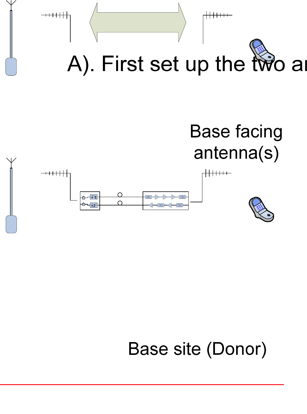
Fibre Optic Master and Remote Site
User Handbook
Document Number: 60-212701HBK - Issue No. 1 Page 41 of 50
5.7 Antenna Isolation

Fibre Optic Master and Remote Site
User Handbook
Document Number: 60-212701HBK - Issue No. 1 Page 42 of 50
6. MAINTENANCE
6.1. Fault Finding
6.1.1. Quick Fault Checklist
All tunnel equipment is individually tested to specification prior to despatch. Failure of this type of
equipment is not common. Experience has shown that a large number of fault conditions relating to
tunnel installations result from simple causes often occurring as result of transportation, unpacking
and installation. Below are listed some common problems which have resulted in poor performance or
an indicated non-functioning of the equipment.
Mains power not connected or not switched on.
External connectors not fitted or incorrectly fitted.
Internal connectors becoming loose due to transport vibration.
Wiring becoming detached as a result of heavy handling.
Input signals not present due to faults in the aerial and feeder system.
Base transmissions not present due to fault at the base station.
Modems fitted with incorrect software configuration.
Changes to channel frequencies and inhibiting channels.
Hand held radio equipment not set to repeater channels.
Hand held radio equipment not set to correct base station.
6.1.2 Fault Isolation
In the event that the performance of the system is suspect, a methodical and logical approach to the
problem will reveal the cause of the difficulty. The System consists of modules fitted in enclosed
shelves within a rack mounted, environmentally protected enclosure.
Transmissions from the main base stations are passed though the system to the mobile radio
equipment; this could be a handheld radio or a transceiver in a vehicle. This path is referred to as the
downlink. The return signal path from the mobile radio equipment to the base station is referred to as
the uplink.
The first operation is to check the alarms of each of the active units and determine that the power
supplies to the equipment are connected and active.
This can be achieved remotely (via CEMS, the RS232 Coverage Enhancement Management System,
if fitted), or locally with the front panel LED’s. The green LED on the front panel should be illuminated,
while the red alarm indicator should be off. If an Alarm is on, then that individual shelf must be
isolated and individually tested against the original test specification.
The individual amplifier units within the shelf have a green LED showing through a hole in their piggy-
back alarm board, which is illuminated if the unit is working correctly. If an amplifier is suspect, check
the DC power supply to the unit. If no other fault is apparent use a spectrum analyser to measure the
incoming signal level at the input and then after reconnecting the amplifier input, measure the output
level. Consult with the system diagram to determine the expected gain and compare result.
In the event that there are no alarms on and all units appear to be functioning it will be necessary to
test the system in a systematic manner to confirm correct operation.

Fibre Optic Master and Remote Site
User Handbook
Document Number: 60-212701HBK - Issue No. 1 Page 43 of 50
6.1.3 Downlink
Confirm that there is a signal at the expected frequency and strength from the base station. If this is
not present then the fault may lay outside the system. To confirm this, inject a downlink frequency
signal from a known source at the master site BTS input and check for output at the remote site
feeder output.
If a signal is not received at the output it will be necessary to follow the downlink path through the
system to find a point at which the signal is lost. The expected downlink output for the given input can
be found in the end-to-end test specification.
6.1.4 Uplink
Testing the uplink involves a similar procedure to the downlink except that the frequencies used are
those transmitted by the mobile equipment.
6.1.5 Fibre Optics
The Fibre Optic transmitters and receivers both have two LED status indicators, one on each module
showing DC power and the other indicating ‘Laser On’ for the transmitter, and ‘Carrier Being
Received’ for the receiver. Assuming that all of the indicators are illuminated, it will be necessary to
check the RF inputs and outputs to the fibre optic units.
Typically the input to transmitter units will be at a level of between -30 and -15 dBm. The RF gain of a
pair (TX to RX) units is factory set to give a 0dB gain, but this is with a short, low loss fibre. In
determining the performance of the link, the insertion loss of the fibre and any power splitters fitted
must be considered. A general rule of thumb figure would be around 0.5 - 1.5dB loss per Kilometre.
6.1.7 Checking service
Following the repair of any part of the system it is recommended that a full end-to-end test is carried
out in accordance with the test specification and that the coverage is checked by survey.
It is important to bear in mind that the system includes a radiating cable network and base stations
that may be faulty or may have been damaged.
6.1.8 Fault repair
Once a faulty component has been identified, a decision must be made on the appropriate course to
carry out a repair. A competent engineer can quickly remedy typical faults such as faulty connections
or cables. The exceptions to this are cable assemblies connecting bandpass filter assemblies that are
manufactured to critical lengths to maintain a 50-ohm system.
Care should be taken when replacing cables or connectors to ensure that items are of the correct
specification. The repair of component modules such as amplifiers and bandpass filters will not
usually be possible in the field, as they frequently require specialist knowledge and test equipment to
ensure correct operation. It is recommended that items of this type are replaced with a spare unit and
the faulty unit returned to AFL for repair.

Fibre Optic Master and Remote Site
User Handbook
Document Number: 60-212701HBK - Issue No. 1 Page 44 of 50
6.1.9 Service Support
Advice and assistance with maintaining and servicing this system are available by contacting
Aerial Facilities Ltd., see section 2.7.
NOTE
Individual modules are not intended to be repaired on site and attempts at repair will
invalidate active warranties. Company policy is that individual modules should be repaired
by replacement. Aerial Facilities Ltd maintains a high level of stock of most modules which
can usually be despatched at short notice to support this policy.
6.2 Tools & Test Equipment
The minimum tools and test equipment needed to successfully service this AFL product are as
follows:-
Spectrum analyser 100kHz to 2GHz (Dynamic range = 90dB).
Signal Generator 30MHz to 2GHz (-120dBm to 0dBm o/p level).
Attenuator 20dB, 10W, DC-2GHz, (N male – N female).
Test Antenna Yagi or dipole for operating frequency.
Optical Power Meter 1300 – 1560nM (-40 - +10dB)
Digital multi-meter Universal Volt-Ohm-Amp meter.
Test cable x 2 N male – N male, 2M long RG214.
Test cable x 2 SMA male – N male, 1m long RG223.
Hand tools Philips #1&2 tip screwdriver.
3mm flat bladed screwdriver.
SMA spanner and torque setter.

Fibre Optic Master and Remote Site
User Handbook
Document Number: 60-212701HBK - Issue No. 1 Page 45 of 50
6.3 Care of Modules
6.3.1 General Comments
Many of the active modules contain semiconductor devices utilising MOS technology, which can be
damaged by electrostatic discharge. Correct handling of such modules is mandatory to ensure their
long-term reliability.
To prevent damage to a module, it must be withdrawn/inserted with care. The module may have
connectors on its underside, which might not be visible to the service operative.
6.3.2 Module Removal (LNAs, general procedure):
The following general instructions should be followed to remove a module:
1 Remove power to the unit
2 Remove all visible connectors (RF, DC & alarm)
3 Release module retaining screws.
4 Slowly but firmly, pull the module straight out of its position. Take care not to twist/turn the
module during withdrawal. (When the module is loose, care may be needed, as there may be
concealed connections underneath).
6.3.3 Module Replacement (general):
1 Carefully align the module into its location then slowly push the module directly straight into its
position, taking care not to twist/turn it during insertion.
2 Reconnect all connectors, RF, alarm, power etc., (concealed connectors may have to be
connected first).
3 Replace retaining screws (if any).
4 Double-check all connections before applying power.
6.3.4 Power Amplifiers
1) Remove power to the unit. (Switch off at mains/battery, or remove DC in connector)
2) Remove alarm wires from alarm screw terminal block or disconnect multi-way alarm
connector.
3) Carefully disconnect the RF input and output coaxial connectors (usually SMA)
If alarm board removal is not required, go to step 5.
4) There is (usually) a plate attached to the alarm board which fixes it to the amplifier, remove its
retaining screws and the alarm board can be withdrawn from the amplifier in its entirety. On
certain types of amplifier the alarm board is not mounted on a dedicated mounting plate; in this
case it will have to firstly be removed by unscrewing it from the mounting pillars, in most
cases, the pillars will not have to be removed before lifting the amplifier.
5) If the amplifier to be removed has a heatsink attached, there may be several different ways it
can have been assembled. The most commonly used method, is screws through the front of
the heatsink to threaded screw holes (or nuts and bolts), into the amplifier within the main
case. If the heatsink is mounted on the rear of the main case (e.g., against a wall in the case
of wall mounted enclosures), then the fixing method for the heatsink will be from within the
case, (otherwise the enclosure would have to be removed from the wall in order to remove the
heatsink).

Fibre Optic Master and Remote Site
User Handbook
Document Number: 60-212701HBK - Issue No. 1 Page 46 of 50
When the heatsink has been removed, the amplifier may be unscrewed from the main casing by its
four corner fixings and gently withdrawn.
Fitting a new power amplifier module will be the exact reverse of the above.
Note: Do not forget to apply fresh heatsink compound to the heatsink/main case joint and also
between the amplifier and the main case.
6.3.5 Low Power Amplifier Replacement
Disconnect the mains power supply and disconnect the 24V dc supply connector for the LPA.
Disconnect the RF input and output cables from the LPA.
Disconnect the alarm connector.
Remove the alarm monitoring wires from (D type connector) pins 9 and 10.
Remove the LPA module by removing the four retaining screws, replace with a new LPA module
and secure it with the screws.
Connect the RF cables to the LPA input and output connectors. Reconnect the wires to the
alarm board connector pins 9 and 10.
Reconnect the DC supply connector and turn the mains switch on.
Note: Tighten SMA connectors using only a dedicated SMA torque spanner. If SMA connectors are
over-tightened, irreparable damage will occur. Do not use adjustable pliers to loosen/tighten SMA
connectors.
Also take care not to drop or knock the module as this can damage (or misalign in the case of tuned
passive modules) sensitive internal components. Always store the modules in an environmentally
friendly location
6.3.6 Module Transportation:
To maintain the operation, performance and reliability of any module it must be stored and
transported correctly. Any module not installed in a whole system must be kept in an anti-static bag or
container. These bags or containers are normally identified by being pink or black, and are often
marked with an ESD label. Any module sent back to AFL for investigation/repair must be so
protected. Please contact AFL’s quality department before returning a module, see section 2.7.

Fibre Optic Master and Remote Site
User Handbook
Document Number: 60-212701HBK - Issue No. 1 Page 47 of 50
APPENDIX A
A.1. Glossary of Terms used in this document
Repeater or
Cell Enhancer
A Radio Frequency (RF) amplifier which can simultaneously
amplify and re-broadcast Mobile Station (MS) and Base
Transceiver Station (BTS) signals.
Band Selective
Repeater
A Cell Enhancer designed for operation on a range of channels
within a specified frequency band.
Channel Selective
Repeater
A Cell Enhancer, designed for operation on specified channel(s)
within a specified frequency band. Channel frequencies may be
factory set or on-site programmable.
AC Alternating Current
AGC Automatic Gain Control
BBU Battery Backup Unit
BTS Base Transceiver Station
CEMS Coverage Enhanced Management System
C/NR Carrier-to-Noise Ratio
DC Direct Current
Downlink (D/L) RF signals TX from the BTS to the Master Site
FO Fibre Optic
GND Ground
ID Identification Number
LED Light Emitting Diode
LNA Low Noise Amplifier
LPA Low Power Amplifier
MOU Master Optical Unit
M.S. Mobile Station
MTBF Mean Time Between Failures
N/A Not Applicable
N/C No Connection
OFR On Frequency Repeater
OIP3 Output Third Order Intercept Point
P1dB 1dB Compression Point
PA Power Amplifier
RF Radio Frequency
RSA Receiver/Splitter Amplifier
RX Receiver
S/N Serial Number
TX Transmitter
Uplink (U/L) RF signals transmitted from the MS to the BTS
VSWR Voltage Standing Wave Ratio
WDM Wave division multiplex
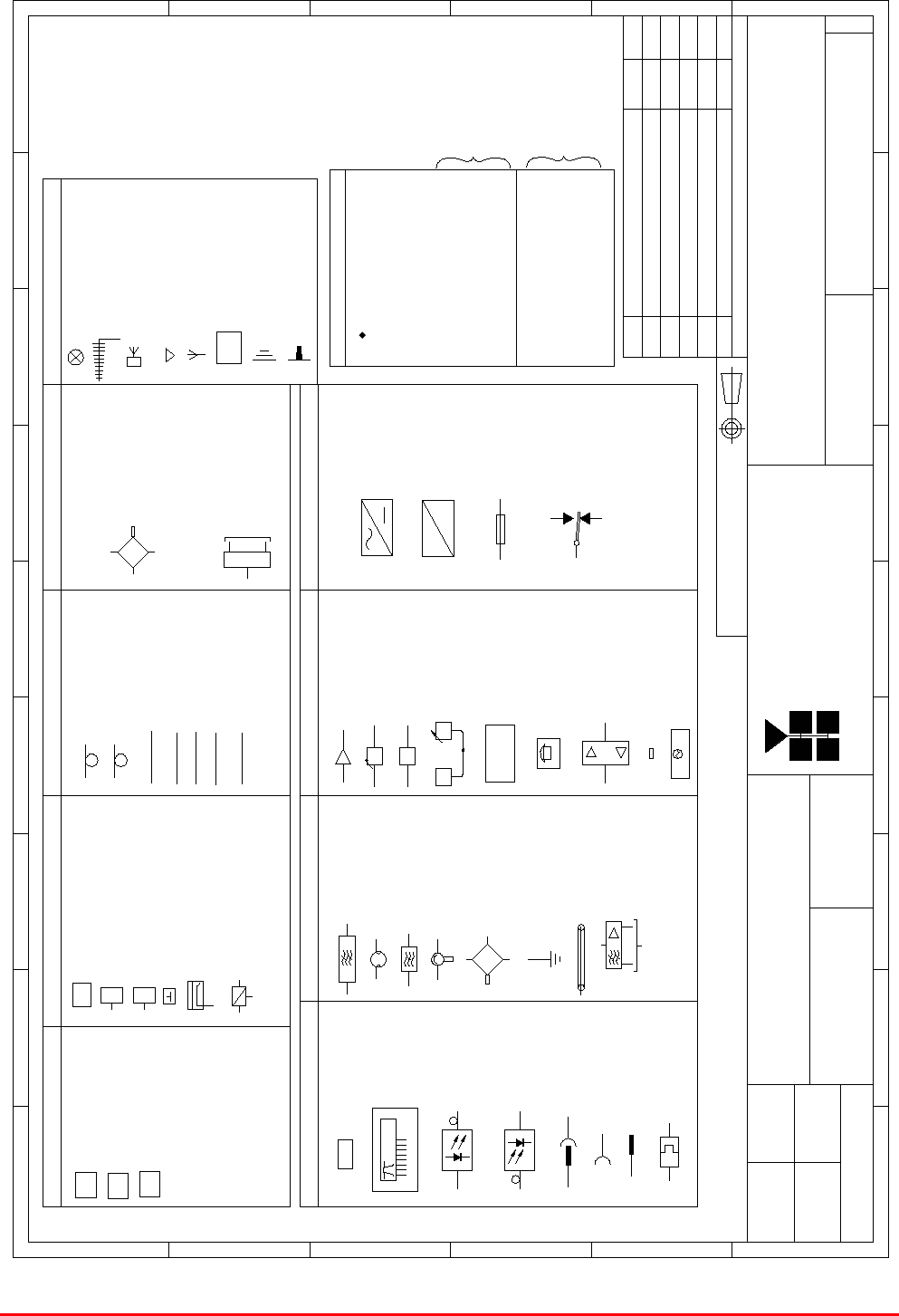
Fibre Optic Master and Remote Site
User Handbook
Document Number: 60-212701HBK - Issue No. 1 Page 48 of 50
C0-AX CABLE
C0-AX CABLE
CAT 5 CABLE
CABLES
24/FIBRE OPTIC CABLE/LINK
CABLE 1/2"
RADIATING CABLE
TAPPER/COUPLER
STATION
BASE TRANSCEIVER
MISC
HUBS
FIBRE MAIN HUB
EXPANSION HUB
BI-DIRECTIONAL AMPLIFIER
E
BTS
FMH
EH
7/8" DIA
1/2" DIA
6dB DIRECTIONAL COUPLER
10dB COUPLER
C10
CROSS BAND COUPLER
COUPLERS
J JUMPER
C6
C10 10dB DIRECTIONAL COUPLER
6 dB DIRECTIONAL COUPLER
DIRECTIONAL COUPLER
PANEL ANTENNA
(MOUNTED AT HIGH LEVEL)
DIRECTIONAL ANTENNA
FLAT PLATE ANTENNA
YAGI ANTENNA
ANTENNAS
REMOTE ANTENNA UNIT
OMNI ANTENNA
SPLITTERS
ANTENNA
RAU
BAND PASS FILTER
CAVITY RESONATOR
NOTCH FILTER
ISOLATOR
HYBRID COMBINER
EARTH STUD
LEEKY FEEDER
Outputs to receivers
R.S.A
AMPLIFIER
MISC
dB ATTENUATOR (VARIABLE)
A.G.C
AGC dB
CONTROLLER
MONITORING
MODEM
MONITORING CONTROLLER
MODEM
(CELL ENHANCER)
FREQUENCY PROGRAMMING
DATA
B/W=30 to 200kHz
CHANNEL MODULE
FIBRE-OPTIC
MODULATOR
FIBRE-OPTIC
DEMODULATOR
LOCAL OSCILLATOR
(up to
16 way)
Outputs
DUMMY LOAD
LOCAL OSCILLATOR
SPLITTER
MISC
8/FIBRE OPTIC CABLE/LINK
STANDARD FOR
LEVEL (dBm)
-73 = BELOW ACCEPTABLE
SIGNAL LEVEL(dBm)
ALL AIRPORTS
BCCH (BROADCAST
IDENTITY CODE)
BSIC (BASIC SITE
LEVEL (dBm)
-83 = BELOW ACCEPTABLE
SIGNAL LEVEL(dBm)
-82 = ACCEPTABLE SIGNAL
-72 = ACCEPTABLE SIGNAL
CONTROL CHANNEL)
= READING POSITION
22 =
602 =
SIGNAL KEY
STANDARD EXCEPT
FOR AIRPORTS
(SEE BELOW)
BLADE ANTENNA
ATTENUATOR (FIXED)
dB
OUTIN
COUPLED
HI COM
LOW
HYBRID SPLITTER
IN
IN
OUT
OUT
IN
OUT
BYDATEDESCRIPTIONNo
THIRD ANGLE PROJECTION
123456789
A
B
C
D
E
F
123
456789
A
B
C
D
E
Fax : 01494 777002
Tel : 01494 777000
Aerial Facilities Limited
THIS IS A PROPRIETARY DESIGN OF AERIAL FACILITIES LTD.
REPRODUCTION OR USE OF THIS DESIGN BY OTHERS IS
PERMISSIBLE ONLY IF EXPRESSLY AUTHORISED IN WRITING
BY AERIAL FACILITIES LTD.
NO DECIMAL PLACE ± 1mm
ONE DECIMAL PLACE ± 0.3mm
TWO DECIMAL PLACES ± 0.1mm
ALL DIMENSIONS ARE IN mm
UNLESS OTHERWISE STATED
CHKD
DRAWN
APPD
DATE
TOLERANCES SCALE
England
90-000001
AA
NTS
PL 10/05/00
ORIGINAL
ISSUE
PL
23/05/00
21/06/00 PLBLADE ANTENNA ADDED1A
2A ECN3165
RF
RF
PLUG & SOCKET
FIBRE OPTIC
CONNECTOR
FC/APC
SOCKET
PLUG
MISC
DC
DC
AC TO DC PSU
DC TO DC
CONVERTER
FUSE
RELAY
N.O. (CLEAR CONTACT)
N.C. (FILLED CONTACT)
COM
MB GD
26/01/04 PL
2B TEXT CORRECTION 28/07/04 PL
ISSUE
F
CUSTOMER DRAWING.No
TITLE
3
A
AFL - STANDARD SYMBOLS
A.2. Key to Drawing Symbols used in this document

Fibre Optic Master and Remote Site
User Handbook
Document Number: 60-212701HBK - Issue No. 1 Page 49 of 50