PBE Europe as Axell Wireless 60-2147SERIES 60-2147 Series Fibre Feed Remote Booster User Manual Manual
Axell Wireless 60-2147 Series Fibre Feed Remote Booster Manual
Manual

Axell Wireless Limited
Technical Literature
Lincoln/Holland Upgrade Equipment
Document Number
60
-
214701HBKM
Issue No.
1
Date
29/08/2008
Page
1
of
43
Aerial Facilities Limited
Lincoln/Holland Upgrade Equipment
User/Maintenance Handbook
For
Concourse Communications Group
AWL Works Order Q116786
AWL Product Part Nos.
Tri-Band Cable Signal Combiner 60-214702
Fibre Fed Remote Repeater 60-214701
Redundant PSU + Battery Backup 60-214703
AFL and Avitec have merged to form Axell Wireless
AXELL WIRELESS UK
Aerial House
Asheridge Road
Chesham, Buckinghamshire
HP5 2QD, United Kingdom
Tel: + 44 (0) 1494 777000
Fax: + 44 (0) 1494 777002
info@axellwireless.com
www.axellwireless.com
AXELL WIRELESS SWEDEN
Box 7139
174 07 Sundbyberg
Sweden
Tel: + 46 (0) 8 475 4700
Fax: + 46 (0) 8 475 4799

Axell Wireless Limited
Technical Literature
Lincoln/Holland Upgrade Equipment
Document Number
60
-
214701HBKM
Issue No.
1
Date
29/08/2008
Page
2
of
43
Table of Contents
1.
Introduction ................................................................................................................................ 4
1.1.
Scope and Purpose of Document ......................................................................................... 4
1.2.
Limitation of Liability Notice .................................................................................................. 4
2.
Safety Considerations ................................................................................................................ 5
2.1.
Earthing of Equipment .......................................................................................................... 5
2.2.
Electric Shock Hazard .......................................................................................................... 5
2.3.
RF Radiation Hazard ............................................................................................................ 5
2.4.
Lifting and other Health and Safety Recommendations ........................................................ 5
2.5.
Chemical Hazard .................................................................................................................. 6
2.6.
Laser Safety ......................................................................................................................... 6
2.7.
Emergency Contact Numbers ............................................................................................... 6
3.
Tri-Band Cable Signal Combiner 60-214702 .............................................................................. 7
3.1.
Tri-Band Combiner 60-214702 Simplified Arrangement Sketch ............................................ 7
3.2.
Tri-Band Combiner 60-214702 Circuit Schematic ................................................................. 8
3.3.
Tri-Band Combiner 60-214702 Alarm Wiring Diagram ......................................................... 9
3.4.
Tri-Band Combiner 60-214702 External Features ............................................................... 10
3.5.
Tri-Band Combiner 60-214702 RF Connections on underside of case ............................... 11
3.6.
Tri-Band Combiner 60-214702 Connections on R.H. Side of case ..................................... 12
3.7.
Tri-Band Combiner 60-214702 Specification ...................................................................... 13
3.8.
Tri-Band Combiner 60-214702 List of Major Sub-Components ........................................... 15
4.
Fibre Fed Remote Repeater 60-214701 ................................................................................... 16
4.1.
Remote Repeater 60-214701 Simplified Arrangement Sketch ............................................ 16
4.2.
Remote Repeater 60-214701 Circuit Schematic ................................................................. 17
4.3.
Remote Repeater 60-214701 Alarm Wiring Diagram .......................................................... 18
4.4.
Remote Repeater 60-214701 Front View ........................................................................... 19
4.5
Remote Repeater 60-214701 Underside View .................................................................... 20
4.6.
Remote Repeater 60-214701 Three-quarter View .............................................................. 21
4.7.
Remote Repeater 60-214701 Interior View ......................................................................... 22
4.8.
Remote Repeater 60-214701 Specification ........................................................................ 23
4.9.
Remote Repeater 60-214701 List of Major Sub-Components ............................................. 24
5.
PSU and Battery Backup 60-214703 ........................................................................................ 25
5.1.
PSU and Battery Backup 60-214703 Simplified Arrangement Sketch ................................. 25
5.2.
PSU and Battery Backup 60-214703 Circuit Diagram ......................................................... 26
5.3.
PSU and Battery Backup 60-214703 External Features ..................................................... 27
5.3.1.
External LEDs ................................................................................................................. 28
5.3.2.
Power and Alarm Ports ................................................................................................... 28
5.4.
PSU and Battery Backup 60-214703 Internal Features....................................................... 29
5.5.
PSU and Battery Backup 60-214703 Specification ............................................................. 30
5.6.
PSU and Battery Backup 60-214703 Major Sub Components ............................................ 30
5.6.1.
Batteries 96-000004 ....................................................................................................... 30
6.
Installation – General Notes ..................................................................................................... 31
6.1
General Remarks ............................................................................................................... 31
6.2
Electrical Connections ........................................................................................................ 31
6.3
RF Connections .................................................................................................................. 31
6.3.1. Termination of Unused Ports .............................................................................................. 31
6.4
Optical Connections ........................................................................................................... 31
6.5
Commissioning ................................................................................................................... 32
6.6
Antenna Installation & Gain Calculations ............................................................................ 32
7.
Maintenance – General Notes .................................................................................................. 33
7.1.
Fault Finding ....................................................................................................................... 33
7.1.1.
Quick Fault Checklist ...................................................................................................... 33
7.1.2
Fault Isolation ................................................................................................................. 33
7.1.3
Downlink ......................................................................................................................... 34
7.1.4
Uplink ............................................................................................................................. 34
7.1.5
Fibre Optics .................................................................................................................... 34

Axell Wireless Limited
Technical Literature
Lincoln/Holland Upgrade Equipment
Document Number
60
-
214701HBKM
Issue No.
1
Date
29/08/2008
Page
3
of
43
7.1.7
Checking service ............................................................................................................ 34
7.1.8
Fault repair ..................................................................................................................... 34
7.1.9
Service Support .............................................................................................................. 35
7.2
Tools & Test Equipment ..................................................................................................... 35
7.3
Care of Modules ................................................................................................................. 35
7.3.1
General Comments ......................................................................................................... 35
7.3.2
Module Removal (LNAs, general procedure): ................................................................. 35
7.3.3
Module Replacement (general): ...................................................................................... 36
7.3.4
Power Amplifiers ............................................................................................................. 36
7.3.5
Low Power Amplifier Replacement ................................................................................. 36
7.3.6
Module Transportation: ................................................................................................... 37
Appendix A ........................................................................................................................................ 38
A.1.
Glossary of Terms used in this document ........................................................................... 38
A.2.
Key to Drawing Symbols used in this document ................................................................. 39
A.3.
EC Declaration of Conformity ............................................................................................. 40
A.4.
Waste Electrical and Electronic Equipment (WEEE) Notice ................................................ 41
A.5.
Document Amendment Record ........................................................................................... 42
Appendix B ........................................................................................................................................ 43
B.1
Initial Equipment Set-Up Calculations ................................................................................. 43

Axell Wireless Limited
Technical Literature
Lincoln/Holland Upgrade Equipment
Document Number
60
-
214701HBKM
Issue No.
1
Date
29/08/2008
Page
4
of
43
1. Introduction
1.1. Scope and Purpose of Document
This handbook is for use solely with the equipment identified by the Axell Wireless Limited (AWL) Part
Number shown on the front cover. It is not to be used with any other equipment unless specifically
authorised by AWL. This is a controlled release document and, as such, becomes a part of the Axell
Wireless Total Quality Management System. Alterations and modification may therefore only be
performed by Axell Wireless.
AWL recommends that the installer of this equipment familiarise themselves with the safety and
installation procedures contained within this document before installation commences.
The purpose of this handbook is to provide the user/maintainer with sufficient information to service
and repair the equipment to the level agreed. Maintenance and adjustments to any deeper level must
be performed by AWL, normally at the company’s repair facility in Chesham, England.
This handbook has been prepared in accordance with BS 4884, and AWL’s Quality procedures, which
maintain the company’s registration to BS EN ISO 9001:2000 and to the R&TTE Directive of the
European Parliament. Copies of the relevant certificates and the company Quality Manual can be
supplied on application to the Operations Support Director (see section 2.7.).
This document fulfils the relevant requirements of Article 6 of the R&TTE Directive.
1.2. Limitation of Liability Notice
This manual is written for the use of technically competent operators/service persons. No liability is
accepted by AWL for use or misuse of this manual, the information contained therein, or the
consequences of any actions resulting from the use of the said information, including, but not limited
to, descriptive, procedural, typographical, arithmetical, or listing errors.
Furthermore, AWL does not warrant the absolute accuracy of the information contained within this
manual, or its completeness, fitness for purpose, or scope.
AWL has a policy of continuous product development and enhancement, and as such, reserves the
right to amend, alter, update and generally change the contents, appearance and pertinence of this
document without notice.
All AWL products carry a twelve month warranty from date of shipment. The warranty is expressly on
a return to base repair or exchange basis and the warranty cover does not extend to on-site repair or
complete unit exchange.
Axell Wireless Limited
Technical Literature
Lincoln/Holland Upgrade Equipment
Document Number
60
-
214701HBKM
Issue No.
1
Date
29/08/2008
Page
5
of
43
2. Safety Considerations
2.1. Earthing of Equipment
Equipment supplied from the mains must be connected to grounded outlets and earthed
in conformity with appropriate local, national and international electricity supply and
safety regulations.
2.2. Electric Shock Hazard
The risk of electrical shocks due to faulty mains driven power supplies whilst
potentially ever present in any electrical equipment, would be minimised by adherence
to good installation practice and thorough testing at the following stages:
All test equipment must be in good working order prior to its use. High current power supplies can be
dangerous because of the possibility of substantial arcing. Always switch off during disconnection and
reconnection.
2.3. RF Radiation Hazard
RF radiation, (especially at UHF frequencies) arising from transmitter outputs
connected to AWL’s equipment, must be considered a safety hazard.
This condition might only occur in the event of cable disconnection, or because a
‘spare’ output has been left un-terminated. Either of these conditions would impair the
system’s efficiency. No investigation should be carried out until all RF power sources have been
removed. This would always be a wise precaution, despite the severe mismatch between the
impedance of an N type connector at 50Ω, and that of free space at 377Ω, which would severely
mitigate against the efficient radiation of RF power. Radio frequency burns could also be a hazard, if
any RF power carrying components were to be carelessly touched!
Antenna positions should be chosen to comply with requirements (both local & statutory) regarding
exposure of personnel to RF radiation. When connected to an antenna, the unit is capable of
producing RF field strengths, which may exceed guideline safe values especially if used with
antennas having appreciable gain. In this regard the use of directional antennas with backscreens
and a strict site rule that personnel must remain behind the screen while the RF power is on, is
strongly recommended.
Where the equipment is used near power lines or in association with temporary masts not having
lightning protection, the use of a safety earth connected to the case-earthing bolt is strongly advised.
2.4. Lifting and other Health and Safety Recommendations
Certain items of AWL equipment are heavy and care should be taken when lifting them
by hand. Ensure that a suitable number of personnel, appropriate lifting apparatus
and appropriate personal protective equipment is used especially when installing Cell
Enhancers above ground e.g. on a mast or pole.
a) Original assembly.
b) Commissioning.
c) Regular intervals, thereafter.

Axell Wireless Limited
Technical Literature
Lincoln/Holland Upgrade Equipment
Document Number
60
-
214701HBKM
Issue No.
1
Date
29/08/2008
Page
6
of
43
2.5. Chemical Hazard
Beryllium Oxide, also known as Beryllium Monoxide, or Thermalox™, is sometimes
used in devices within equipment produced by Axell Wireless Ltd. Beryllium oxide dust
can be toxic if inhaled, leading to chronic respiratory problems. It is harmless if
ingested or by contact.
Products that contain beryllium are load terminations (dummy loads) and some power amplifiers.
These products can be identified by a yellow and black “skull and crossbones” danger symbol (shown
above). They are marked as hazardous in line with international regulations, but pose no threat under
normal circumstances. Only if a component containing beryllium oxide has suffered catastrophic
failure, or exploded, will there be any danger of the formation of dust. Any dust that has been created
will be contained within the equipment module as long as the module remains sealed. For this reason,
any module carrying the yellow and black danger sign should not be opened. If the equipment is
suspected of failure, or is at the end of its life-cycle, it must be returned to Axell Wireless Ltd. for
disposal.
To return such equipment, please contact the Operations Support Department, who will give you a
Returned Materials Authorisation (RMA) number. Please quote this number on the packing
documents, and on all correspondence relating to the shipment.
PolyTetraFluoroEthylene, (P.T.F.E.) and P.T.F.E. Composite Materials
Many modules/components in AWL equipment contain P.T.F.E. as part of the RF insulation barrier.
This material should never be heated to the point where smoke or fumes are evolved. Any person
feeling drowsy after coming into contact with P.T.F.E. especially dust or fumes should seek medical
attention.
2.6. Laser Safety
General good working practices adapted from
EN60825-2: 2004/ EC 60825-2:2004
Do not stare with unprotected eyes or with any unapproved optical device at the fibre
ends or connector faces or point them at other people, Use only approved filtered or attenuating
viewing aids.
Any single or multiple fibre end or ends found not to be terminated (for example, matched, spliced)
shall be individually or collectively covered when not being worked on. They shall not be readily
visible and sharp ends shall not be exposed.
When using test cords, the optical power source shall be the last connected and the first
disconnected; use only approved methods for cleaning and preparing optical fibres and optical
connectors.
Always keep optical connectors covered to avoid physical damage and do not allow any dirt/foreign
material ingress on the optical connector bulkheads.
The optical fibre jumper cable maximum bend radius is 3cm; any smaller radii may result in optical
cable breakage or excessive transmission losses.
Caution: The FO units are NOT weather proof.
2.7. Emergency Contact Numbers
The AWL Operations Support Department can be contacted on:
Telephone +44 (0)1494 777000
Fax. +44 (0)1494 777002
e-mail qa@axellwireless.com
Axell Wireless Limited
Technical Literature
Lincoln/Holland Upgrade Equipment
Document Number
60
-
214701HBKM
Issue No.
1
Date
29/08/2008
Page
7
of
43
Base
stations
Warning! The door is not attached when unlocked
3. Tri-Band Cable Signal Combiner 60-214702
Tri-Band Combiner 60-214702 is built into a wall-mounted, environmentally protected (IP65)
aluminium alloy case; RF ports and connectors are also IP65 standard making the entire enclosure
and connecting ports weatherproof. The door is fitted with three locking door handles which also
serve to locate the door onto the case. Caution, the door is not attached to the case when the locking
door handles are opened.
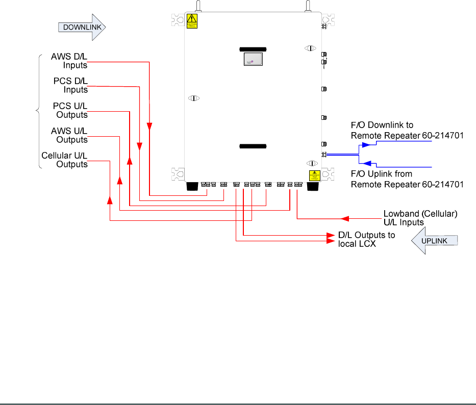
The Combiner has connections for various RF inputs and outputs across three bands; AWS, PCN and
Cellular.
AWS and PCN Downlink signals are received from the operators’ base stations, filtered and combined
into a single path and then passed to local LCX antannas, a portion of the Downlink signal is tapped
off and fed to a fibre optic transmitter which modulates the RF signal onto a laser for transmission to
the Remote Repeater 60-214701 as optical signals over fibre optic cable.
AWS and PCN Uplink signals are received from the local LCX antannas, filtered and amplified before
being split into their respective band/frequency allocations and fed to the operators’ base stations.
Optical signals from the Remote Repeater 60-214701 are demodulated to RF and combined with the
Uplink signal from the LCX antennas after the amplification stages.
The Cellular signal path is in the Uplink direction only, Signals are received, filtered and amplified
before being fed to the operators’ base stations.
3.1. Tri-Band Combiner 60-214702 Simplified Arrangement Sketch
60-214702 features dual redundant amplification stages in the Uplink bands so that in case of any
single amplifier failure, complete signal loss would not occur in that path, allowing continued
coverage. It also has a comprehensive alarm system (each amplifier module carries its own voltage-
free contact alarm relay output). 60-214702 is powered from an AC supply at 110V.
Caution must be exercised when attempting to move or lift this unit as the gross weight of the unit is in
excess of 90kg (200lbs)
Axell Wireless Limited
Technical Literature
Lincoln/Holland Upgrade Equipment
Document Number
60
-
214701HBKM
Issue No.
1
Date
29/08/2008
Page
8
of
43
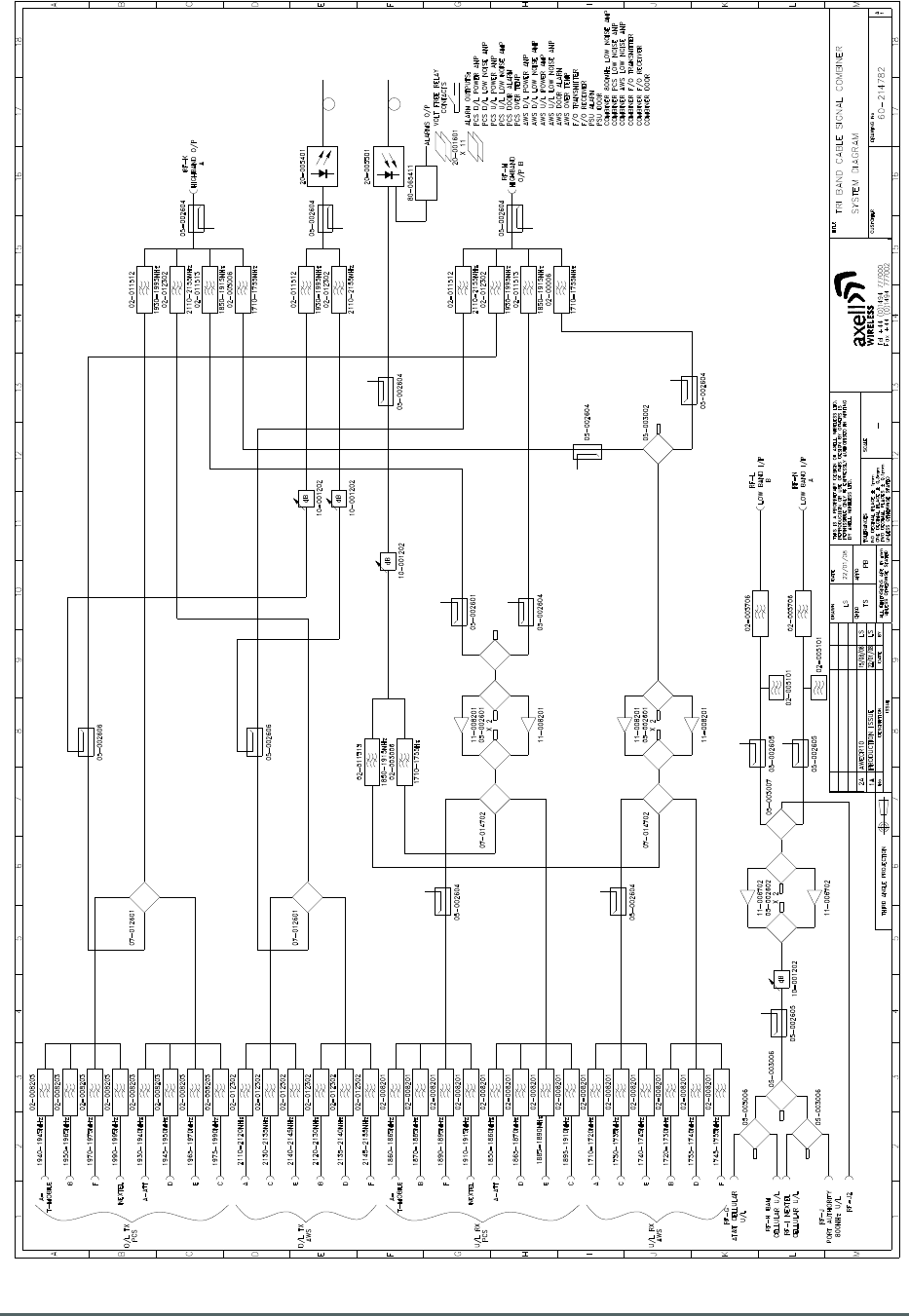
3.2. Tri-Band Combiner 60-214702 Circuit Schematic
Drawing Number 60-214782
Axell Wireless Limited
Technical Literature
Lincoln/Holland Upgrade Equipment
Document Number
60
-
214701HBKM
Issue No.
1
Date
29/08/2008
Page
9
of
43
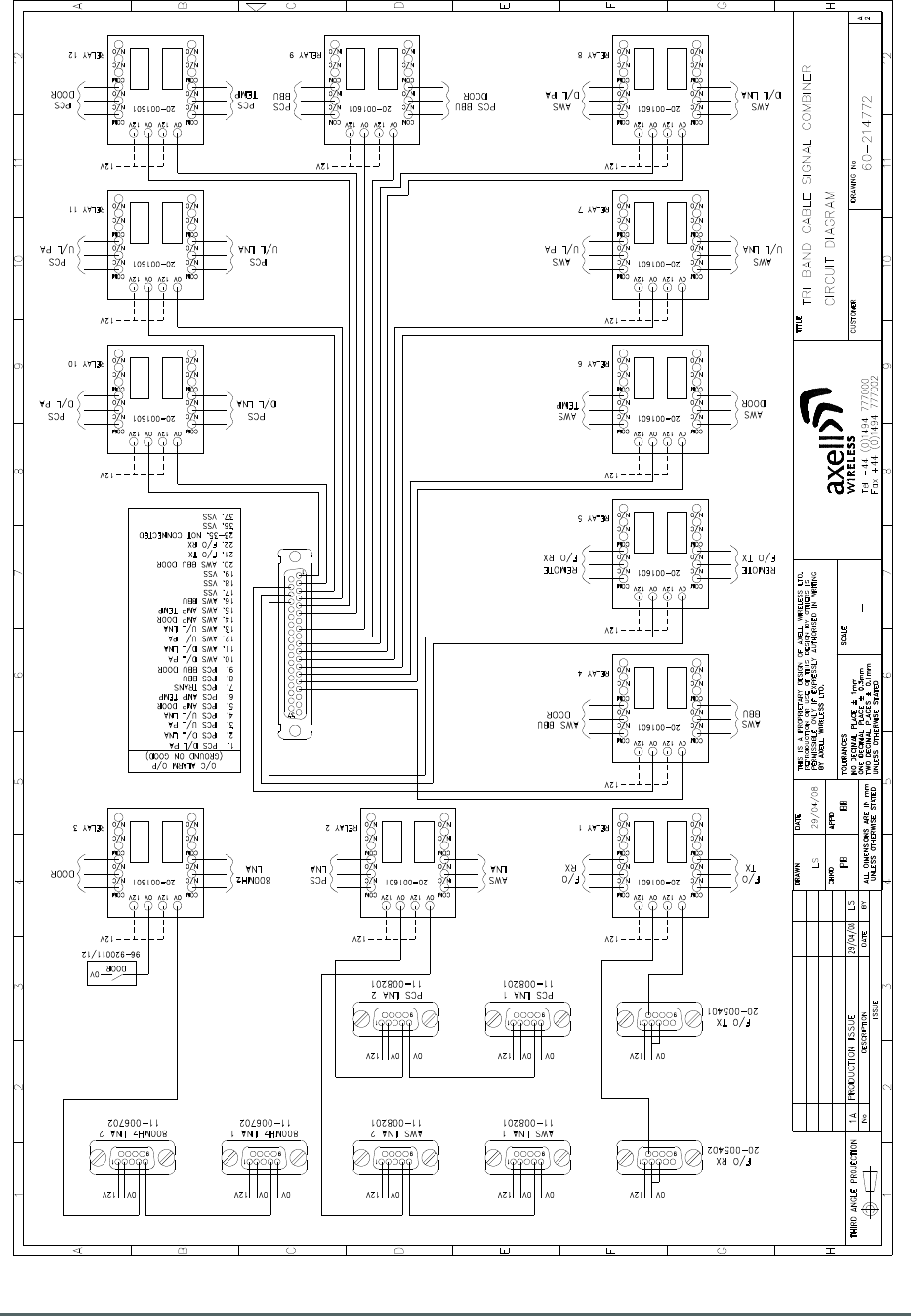
3.3. Tri-Band Combiner 60-214702 Alarm Wiring Diagram
Drawing Number 60-214772
Axell Wireless Limited
Technical Literature
Lincoln/Holland Upgrade Equipment
Document Number
60
-
214701HBKM
Issue No.
1
Date
29/08/2008
Page
10
of
43
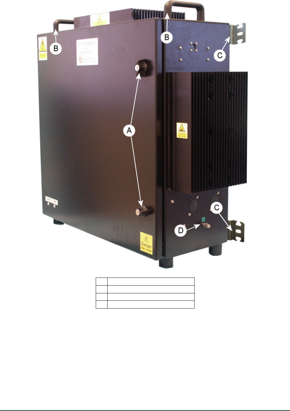
3.4. Tri-Band Combiner 60-214702 External Features
A RF Inputs and Outputs (see section 3.5. below)
B
RF Monitor/Test ports
(see section 3.
6
. below)
C Cable Gland for Fibre Optic Cable Input/Output
D AC Mains Input
E Lockable door handles
F Wall mounting brackets
G Door Lifting handles
Note: Door is not fixed to body when Lockable door handles (E) are open.
Axell Wireless Limited
Technical Literature
Lincoln/Holland Upgrade Equipment
Document Number
60
-
214701HBKM
Issue No.
1
Date
29/08/2008
Page
11
of
43
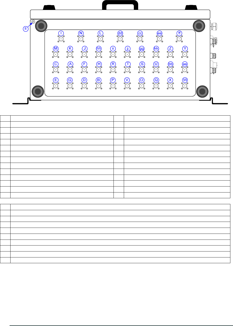
3.5. Tri-Band Combiner 60-214702 RF Connections on underside of case
A PCS D/L I/P port “A-AT&T” 1930-1940MHz O PCS U/L O/P port “A-AT&T” 1850-1860MHz
B PCS D/L I/P port “A-T Mobile” 1940-1945MHz
P PCS U/L O/P port “A-T Mobile” 1860-1865MHz
C PCS D/L I/P port “D” 1945-1950MHz Q PCS U/L O/P port “D” 1865-1870MHz
D PCS D/L I/P port “B” 1950-1965MHz R PCS U/L O/P port “B” 1870-1885MHz
E PCS D/L I/P port “E” 1965-1970MHz S PCS U/L O/P port “E” 1885-1890MHz
F PCS D/L I/P port “F” 1970-1975MHz T PCS U/L O/P port “F” 1890-1895MHz
G PCS D/L I/P port “C” 1975-1990MHz U PCS U/L O/P port “C” 1895-1910MHz
H PCS D/L I/P port “Nextel” 1990-1995MHz V PCS U/L O/P port “Nextel” 1910-1915MHz
I AWS D/L I/P port “A” 2110-2120MHz W AWS U/L O/P port “A” 1710-1720MHz
J AWS D/L I/P port “B” 2120-2130MHz X AWS U/L O/P port “B” 1720-1730MHz
K AWS D/L I/P port “C” 2130-2135MHz Y AWS U/L O/P port “C” 1730-1735MHz
L AWS D/L I/P port “D” 2135-2140MHz Z AWS U/L O/P port “D” 1735-1740MHz
M AWS D/L I/P port “E” 2140-2145MHz aa
AWS U/L O/P port “E” 1740-1745MHz
N AWS D/L I/P port “F” 2145-2155MHz bb
AWS U/L O/P port “F” 1745-1755MHz
cc Highband (PCS+AWS) Output to/Input from Local LCX port “RF-K”
dd
Highband (PCS+AWS) Output to/Input from Local LCX port “RF-M”
ee
Lowband (Cellular) U/P I/P port “RF-L”
ff Lowband (Cellular) U/P I/P port “RF-N”
gg
Lowband (Cellular) U/P O/P port “RF-G AT&T Cellular”
hh
Lowband (Cellular) U/P O/P port “RF-H BAM Cellular”
ii Lowband (Cellular) U/P O/P port “RF-I NEXTEL Cellular”
jj Lowband (Cellular) U/P O/P port “RF-J Port Authority 800 MHz”
kk Lowband (Cellular) U/P O/P port “RF-J2”
ll Earthing Connection
Axell Wireless Limited
Technical Literature
Lincoln/Holland Upgrade Equipment
Document Number
60
-
214701HBKM
Issue No.
1
Date
29/08/2008
Page
12
of
43
110V
A B C D
E F G H
I J K
L
M
N
O
P
Q
P
R
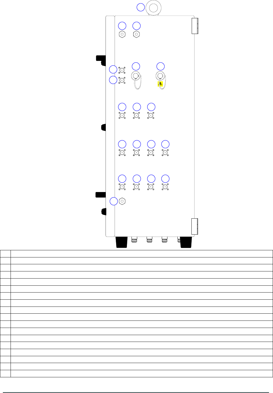
3.6. Tri-Band Combiner 60-214702 Connections on R.H. Side of case
A 30dB Monitor Port coupled from D/L Output port “RF-M” (“dd” in section 3.5.).
B 30dB Monitor Port coupled from RF from F/O Uplink Input.
C 30dB Monitor Port coupled from RF from F/O Downlink Output.
D
30dB Monitor Port coupled from D/L Output
port “RF
-
K
” (“
cc
” in section 3.
5
.)
.
E 30dB Monitor Port for AWS U/L Input coupled from port “RF-K” (“cc” in section 3.5.).
F 30dB Monitor Port for AWS U/L Input coupled from port “RF-M” (“dd” in section 3.5.).
G
30dB Monitor Port for PCS U/L Input coupled from port “RF-K” (“cc” in section 3.5.).
H 30dB Monitor Port for PCS U/L Input coupled from port “RF-M” (“dd” in section 3.5.).
I 30dB Monitor Port coupled from Lowband (Cellular) U/L Output ports (“gg” to “kk” in section 3.5.).
J 30dB Monitor Port coupled from Lowband (Cellular) U/L Input port “RF-L” (“ee” in section 3.5.).
K
30dB Monito
r Port coupled from
Lowband (Cellular) U/L
Input
port “RF
-
N” (“ff” in section 3.
5
.).
L 30dB Monitor Port coupled from AWS Uplink Output Ports (“W”, “Y” & “aa” in section 3.5.).
M
30dB Monitor Port coupled from PCS Uplink Output Ports (“P”, “R”, “T” & “V” in section 3.5.).
N Spare port
O
Cable Gland for Fibre Optic Cables.
P
Spare cable Glands
Q
AC Mains Input 110V
R Lifting Eyes

Axell Wireless Limited
Technical Literature
Lincoln/Holland Upgrade Equipment
Document Number
60
-
214701HBKM
Issue No.
1
Date
29/08/2008
Page
13
of
43
3.7. Tri-Band Combiner 60-214702 Specification
PARAMETER SPECIFICATION
Frequencies
PCS Downlink
Passbands
T-MOBILE RF-A
1940-1945 MHz
RF-B
1950-1955 MHz
RF
-
F
1970
-
1975 MHz
NEXTEL
1990-1995 MHz
A-ATT
1930-1940 MHz
RF-D
1945-1950 MHz
RF-E
1965-1970 MHz
RF-C
1975-1990 MHz
AWS
Downlink
Passbands
RF-A
2110-2120 MHz
RF
-
C
2130
-
2135 MHz
RF-E
2140-2145 MHz
RF-B
2120-2130 MHz
RF-D
2135-2140 MHz
RF-F
2145-2155 MHz
PCS Uplink
Passbands
T-MOBILE RF-A
1860-1865 MHz
RF-B
1870-1885 MHz
RF
-
F
1890
-
1895 MHz
NEXTEL
1910-1915 MHz
A-ATT
1835-1860 MHz
RF-D
1865-1870 MHz
RF-E
1885-1890 MHz
RF-C
1895-1910 MHz
AWS Uplink
Passbands
RF-A
1710-1720 MHz
RF
-
C
1730
-
1735 MHz
RF-E
1740-1745 MHz
RF-B
1720-1730 MHz
RF-D
1735-1740 MHz
RF-F
1745-1755 MHz
Cellular Uplink
Passband
RF-G, H, I, J
806-849 MHz
Path Losses
Downlink paths to Local LCX
</= 10.0 dB
Cellular Uplink to Port RF
-
J2
6.0 dB typical
Downlink paths to FO TX O/P
40 dB typical
(RF
-
A,B,C,D,E,F) Max Input Power
100 Watts at each Input port
(BTS Inputs) Reurn loss
1.5:1
Path Gains
RF-L to RF-G, H, I, J
RF-N to RF-G, H, I, J
RF-K to RF-A, B, C, D, E, F
RF-M to RF-A, B, C, D, E, F
14 dB typical
14 dB typical
15.0 dB typical
15.0 dB typical
Rejection
RF-L to RF-G,H,I,J
RF-N to RF-G,H,I,J
(851-869 MHz)
15 dB
FO-B to RF-A, B, C, D, E, F (RX)
9.0 dB typical
continued...

Axell Wireless Limited
Technical Literature
Lincoln/Holland Upgrade Equipment
Document Number
60
-
214701HBKM
Issue No.
1
Date
29/08/2008
Page
14
of
43
Tri-Band Combiner 60-214702 Specification continued
General
Impedance
50 Ohms
Alarms Fitted
(summary volt-free contacts)
PCS Downlink Power Amplifier
PCS Downlink LNA
PCS Uplink Power Amplifier
PCS Uplink LNA
PCS Door Alarm
PCS Over Temperature.
AWS Downlink Power Amplifier
AWS Downlink LNA.
AWS Uplink Power Amplifier
AWS Uplink LNA
AWS Door Alarm
AWS Over Temperature
FO Transmitter
FO Receiver
PSU Alarm
PSU Door
Combiner 800 MHz Low Noise
Combiner PCS LNA
Combiner AWS LNA
Combiner FO Receiver
Combiner FO Transmitter
Combiner Door
AC Supply Voltage
110V AC
Redundancy
Parallel modules in all Uplink Amplifier stages
Case Size
896mm x 735mm x 362mm
Case Material
Mild Steel (2mm)
Case Finish
Black Semi-gloss
AC Supply Voltage
110V AC
RF Connectors
N type female
Temperature
Storage
-
40 to +71
°
C
Operating
-10 to +55°C
Humidity
95% RHNC

Axell Wireless Limited
Technical Literature
Lincoln/Holland Upgrade Equipment
Document Number
60
-
214701HBKM
Issue No.
1
Date
29/08/2008
Page
15
of
43
3.8. Tri-Band Combiner 60-214702 List of Major Sub-Components
Component
Part
Component Part Description Qty Per
Assembly
02-003006 Bandpass FIlter 3
02-003706 Bandpass FIlter 2
02-005101 Notch Reject Filter 2
02-008201 Bandpass FIlter 14
02
-
008216
Bandpass FIlter
8
02-011512 Bandpass FIlter 3
02
-
011513
Bandpass FIlter
3
02-012302 Bandpass FIlter 9
05-002601 Splitter/Combiner 4
05-002602 Splitter/Combiner 2
05-002604 20dB Coupler 10
05
-
002605
20dB Coupler
3
05-002606 30dB Coupler 2
05
-
003002
3 Port Hybrid Combiner
2
05-003006 3 Port Hybrid Combiner 3
05-003007 4 Port Hybrid Combiner 1
07-012601 4 Port 2 Way Combiner 2
07-014702 4 Port 2 Way Combiner 2
10
-
001202
Remote Variable Attenuator
4
11-006702 Low Noise Amplifier (800-1000MHz) 2
11
-
008201
Low Noise Amplifier (PCN)
4
20-001601 12V Relay Board 12
20-005401 Fibre Optic Transmitter 1
20-005501 Fibre Optic Receiver 1
80-065411 FO Alarm RX De-Modulator 1
91
-
800003
10 Way Krone Module
7
96-300051 PSU Module 1
Axell Wireless Limited
Technical Literature
Lincoln/Holland Upgrade Equipment
Document Number
60
-
214701HBKM
Issue No.
1
Date
29/08/2008
Page
16
of
43
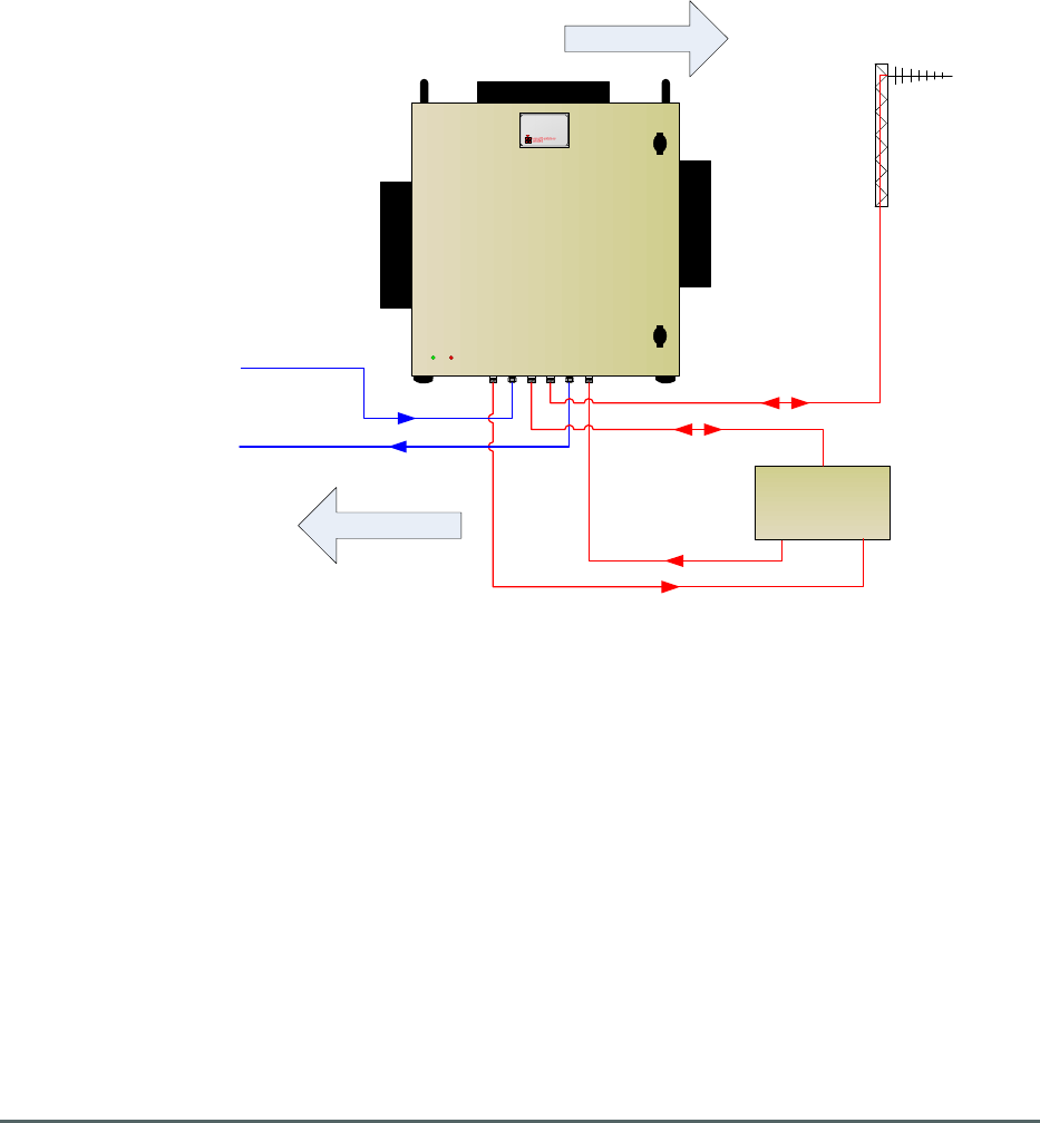
UPLINK
DOWNLINK Antenna facing
Mobiles
60-214701
F/O Downlink from
Combiner 60-214702
F/O Uplink to
Combiner 60-214702
PCS Downlink
PCS Uplink
External PCS
Amplifier
4. Fibre Fed Remote Repeater 60-214701
Remote Repeater 60-214701 is built into a wall-mounted, environmentally protected (IP65) aluminium
alloy case; RF ports and connectors are also IP65 standard making the entire enclosure and
connecting ports weatherproof. Handles are provided for carrying the unit and the door is fitted with
locks and there are Power On and Alarm indicators on the outside of the door.
The Repeater has two fibre optic connections for two fibre optic cables, one carying Downlink signals
from the Tri-Band Cable Signal Combiner 60-214702 and one carying Uplink signals to the Tri-Band
Cable Signal Combiner 60-214702. The Repeater also had an RF connection carying Downlink and
Uplink signals to and from the Antenna facing the mobiles
Provision is made for feeding the PCS signal path out to an existing external PCS bi-directional
amplifier.
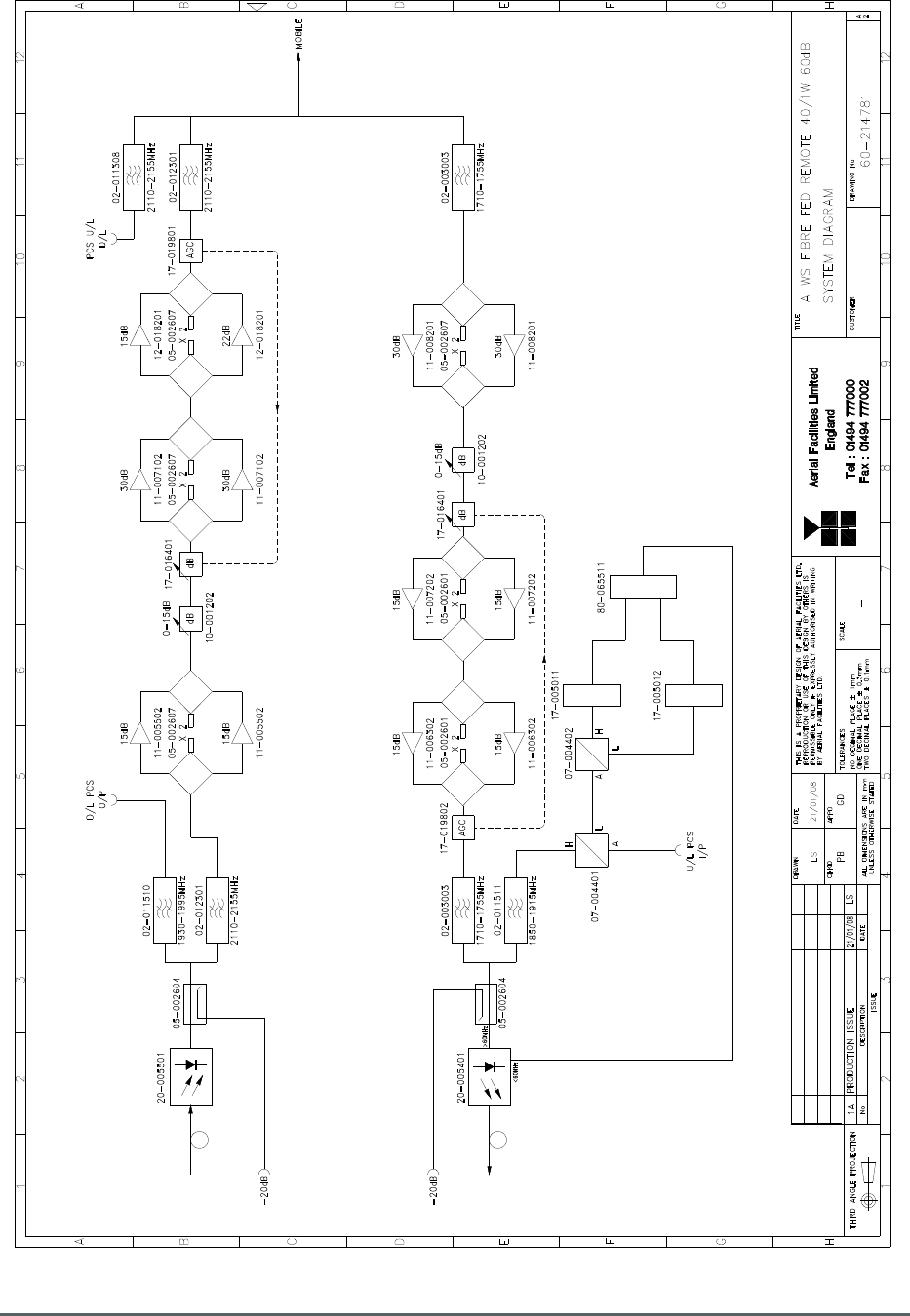
4.1. Remote Repeater 60-214701 Simplified Arrangement Sketch
60-214701 features dual redundant amplification stages in both Downlink and Uplink bands so that in
case of any single amplifier failure, complete signal loss would not occur in that path, allowing
continued coverage. It also has a comprehensive alarm system (each amplifier module carries its own
voltage-free contact alarm relay output), with the capability of remote configuration/alteration through
a multiplexed RS232 base station modem link. 60-214701 is powered from a DC supply at 24V which
is provided by PSU and Battery Backup 60-214703.
Axell Wireless Limited
Technical Literature
Lincoln/Holland Upgrade Equipment
Document Number
60
-
214701HBKM
Issue No.
1
Date
29/08/2008
Page
17
of
43
4.2. Remote Repeater 60-214701 Circuit Schematic
Drawing Number 60-214781
Axell Wireless Limited
Technical Literature
Lincoln/Holland Upgrade Equipment
Document Number
60
-
214701HBKM
Issue No.
1
Date
29/08/2008
Page
18
of
43
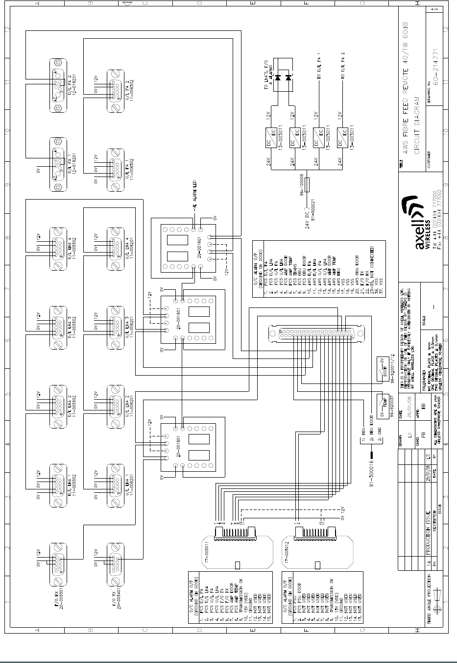
4.3. Remote Repeater 60-214701 Alarm Wiring Diagram
Drawing Number 60-214771
Axell Wireless Limited
Technical Literature
Lincoln/Holland Upgrade Equipment
Document Number
60
-
214701HBKM
Issue No.
1
Date
29/08/2008
Page
19
of
43
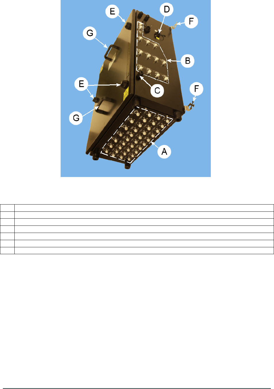
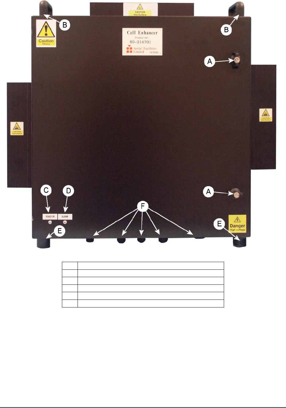
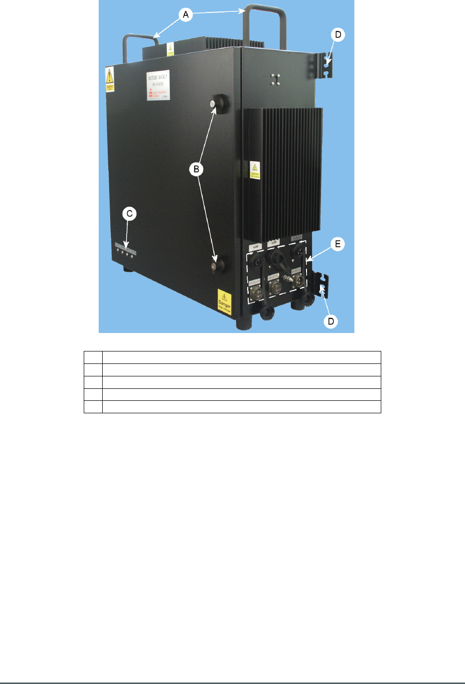
4.4. Remote Repeater 60-214701 Front View
A Lockable Door Handles
B Lifting handles
C Green LED “POWER ON”
D Red LED “ALARM”
E
Rubber F
eet
F Connectors on Underside – see section 4.5.
Axell Wireless Limited
Technical Literature
Lincoln/Holland Upgrade Equipment
Document Number
60
-
214701HBKM
Issue No.
1
Date
29/08/2008
Page
20
of
43
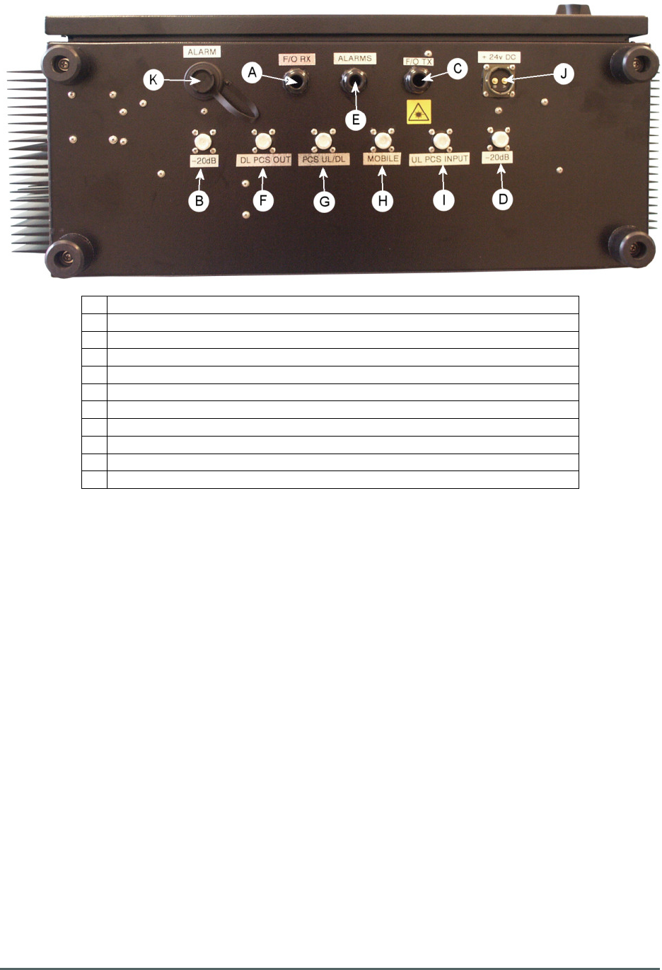
4.5 Remote Repeater 60-214701 Underside View
A Fibre Optic Cable Gland for Downlink from Combiner 60-214702
B 20dB Monitor port for Fibre Optic Downlink Input
C
Fibre Optic Cable Gland for Uplink to Combiner 60-214702
D
20dB Monitor port for Fibre Optic Uplink Output
E Cable Gland for Auxillary Alarms
F
Downlink
RF
PCS Output to External Amplifier
G
Combined RF PCS Downlink from and Uplink to External Amplifier
H
Combined RF Output to/Input from Mobile Antenna
I Uplink RF PCS Input from External Amplifier
J 24V C D Input from PSU and Battery Backup 60-214703
K
Alarm Input from PSU and Battery Backup 60
-
214703
Axell Wireless Limited
Technical Literature
Lincoln/Holland Upgrade Equipment
Document Number
60
-
214701HBKM
Issue No.
1
Date
29/08/2008
Page
21
of
43
4.6. Remote Repeater 60-214701 Three-quarter View
A Lockable Door Handles
B
Lifting handles
C Wall Mounting Brackets
D
Earthing connection
Axell Wireless Limited
Technical Literature
Lincoln/Holland Upgrade Equipment
Document Number
60
-
214701HBKM
Issue No.
1
Date
29/08/2008
Page
22
of
43
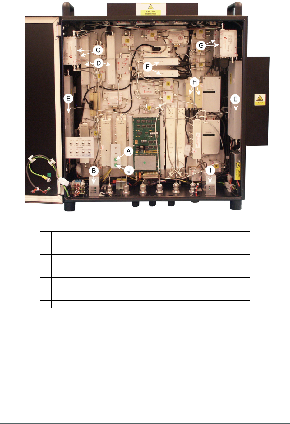
4.7. Remote Repeater 60-214701 Interior View
A Downlink Fibre Optic Input port
B Fibre Optic Receiver 20-005501
C Downlink 1st stage amplifiers - Low Nolise Amplifiers 11-005502
D Downlink 2nd stage amplifiers - Low Power Amplifiers 11-007102
E Downlink 3rd stage amplifiers - Power Amplifiers 12-018201
F Uplink 1st stage amplifiers - Low Nolise Amplifiers 11-008201
G
Uplink 2nd stage amplifiers - Low Noise Amplifiers 11-007202
H Upink 3rd stage amplifiers - Low Power Amplifiers 11-006302
I Fibre Optic Transmitter 20-005401
J
Uplink Fibre Optic Output port

Axell Wireless Limited
Technical Literature
Lincoln/Holland Upgrade Equipment
Document Number
60
-
214701HBKM
Issue No.
1
Date
29/08/2008
Page
23
of
43
4.8. Remote Repeater 60-214701 Specification
PARAMETER SPECIFICATION
DOWNLINK
Passband Frequency
2110-2155MHz
Passband Gain
60 dB
Passband Ripple
<±1.5 dB
Variable Attenuator
2-30 dB (± 1dB)
1dB Compression
+44dB
OIP3
+60dBm
In Band Spurious Noise (30kHz Bandwidth)
< -13dm @ (60dB gain)
PCS Input 1850-1995MHz Insertion Loss
<2dB
UPLINK
Passband Frequency
1710
-
1755 MHz
Passband Gain
>60 dB
Passband Ripple
<±1.5 dB
Variable Attenuator
2-30 dB (± 1dB)
1dB Compression
+30dB
ALC Setting
0 dBm
OIP3
+40dBm
No
ise Figure
<4dB (max.gain)
In Band Spurious Noise (30kHz Bandwidth)
< -13dBm @ (60dB gain)
PCS Input 1850-1915MHz Insertion Loss
<2dB
OPTICAL
Optical Input Alarm Threshold
< -9dBm at 1310nm
F/O TX Output Power
> 1dBm at 1310nm
GENERAL
Case Size (ex.
handles and heatsinks)
620mm x 620mm x 250mm
Case Material
Aluminium Alloy (2mm)
Case Finish
Black Semi-gloss
DC Supply Voltage
24V
RF Connectors
N type female
Optical Connectors
FC/APC
Redundancy
Parallel modules in all Amplifier stages
Alarms Fitted
(summary volt-free contacts)
Over Temperature
Uplink Low Noise Amplifiers Fail
Uplink Power Amplifiers Fail
Downlink Low Noise Amplifiers Fail
Downlink Power Amplifiers Fail
Door Open
FO TX Fail
FO RX Fail
Temperature
Range
operation
-20°C to +60°C
storage
-40°C to +70°
Humidity
95% RHNC

Axell Wireless Limited
Technical Literature
Lincoln/Holland Upgrade Equipment
Document Number
60
-
214701HBKM
Issue No.
1
Date
29/08/2008
Page
24
of
43
4.9. Remote Repeater 60-214701 List of Major Sub-Components
Component
Part
Component Part Description Note Qty Per
Assembly
02-003003 Bandpass Filter 2
02-011308 Bandpass Filter 1
02-011510 Notch Reject Filter 1
02-011511 Notch Reject Filter 1
02
-
012301
Bandpass Filter
2
05-002601 2 Way Splitter/Combiner 6
05-002604 20dB Coupler 2
05-002607 2 Way Splitter/Combiner 6
07-004401 Crossband Coupler 1
07-004402 Crossband Coupler 1
10-001202 Remote Variable Attenuator 2
11
-
005502
Low Noise Amplifier
D/L Stage 1
2
11-006302 1Watt PCN Low Power Amplifier U/L Stage 3 2
11-007102 1Watt UMTS Low Power Amplifier D/L Stage 2 2
11-007202 Low Noise Amplifier U/L Stage 2 2
11-008201 Low Noise Amplifier U/L Stage 1 2
12-018201 20W Power Amplifier D/L Stage 3 2
13-003011 DC/DC Converter 4
17
-
005011
FO Alarm RX Module
21.4MHz
1
17-005012 FO Alarm RX Module 10.7MHz 1
17-016401 AGC Attenuator 2
17-019801 AGC Detector/Amplifier 1
17-019802 AGC Detector/Amplifier 1
20-005401 Fibre Optic Transmitter 1
20-005501 Fibre Optic Receiver 1
80
-
065311
Front Panel Display Sub
-
Assembly
1
80-065511 FO Alarm TX Modulator 1
96-100009 DC Dual Diode Box 1
Axell Wireless Limited
Technical Literature
Lincoln/Holland Upgrade Equipment
Document Number
60
-
214701HBKM
Issue No.
1
Date
29/08/2008
Page
25
of
43
5. PSU and Battery Backup 60-214703
PSU and Battery Backup 60-214703 is built into a wall-mounted, environmentally protected (IP65)
aluminium alloy case; ports and connectors are also IP65 standard making the entire enclosure and
connecting ports weatherproof. The door is fitted with locking door handles and handles are provided
for carrying the unit. There are Power On and Alarm indicators on the outside of the door.
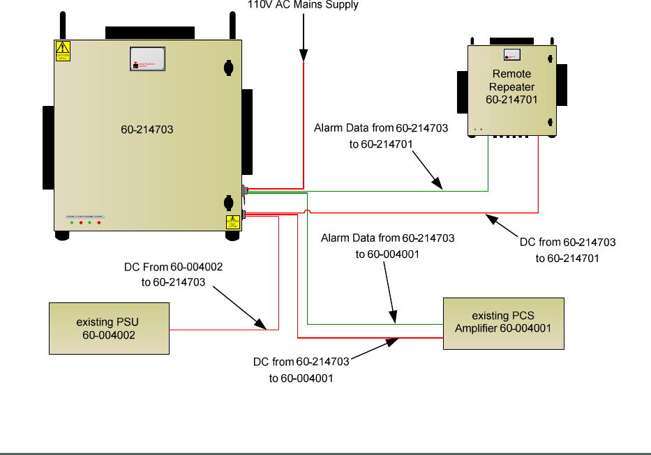
The power supply uses two identical 400Watt mains driven PSU modules connected via power
combining diodes to supply 24V DC power to the Remote site equipment. This wiring arrangement
allows either of the modules to supply power continuously should one of the PSUs fail. Both the PSU
modules are alarmed through a 12V relay PCB and will activate the main alarm should either module
fail. Mains trip switches isolate the AC supply to either PSU module should either need to be switched
off.
The battery backup system operates in parallel with the main AC derived DC supply from the PSU
Modules; thus if the primary AC fails the backup system provides a seamless “no-break” transition
from mains to battery. Four 12V, 38Ah Sealed Lead-Acid batteries are employed, arranged in two
pairs wired in series each pair providing a 24V Output. Pair 1 provides backup for Remote Repeater
60-214701 and Pair 2 provides backup for existing PCS Amplifier 60-004001. During normal
operation the AC mains float charge the batteries via a third mains driven PSU Module.
A Low Voltage Disconnect circuit exists which cuts the battery power to the equipment when the
battery voltage falls below a pre-set threshold. A series regulator circuit ensures that the DC voltage
from the fully charged batteries does not exceed 12V per battery.
All PSU modules are separately alarmed and the summed alarm data is presented at the connector
labelled “N” in section 5.3.2. from where it is fed to Remote Repeater 60-214701 for onward
transmission to the Master Site
5.1. PSU and Battery Backup 60-214703 Simplified Arrangement Sketch
Axell Wireless Limited
Technical Literature
Lincoln/Holland Upgrade Equipment
Document Number
60
-
214701HBKM
Issue No.
1
Date
29/08/2008
Page
26
of
43
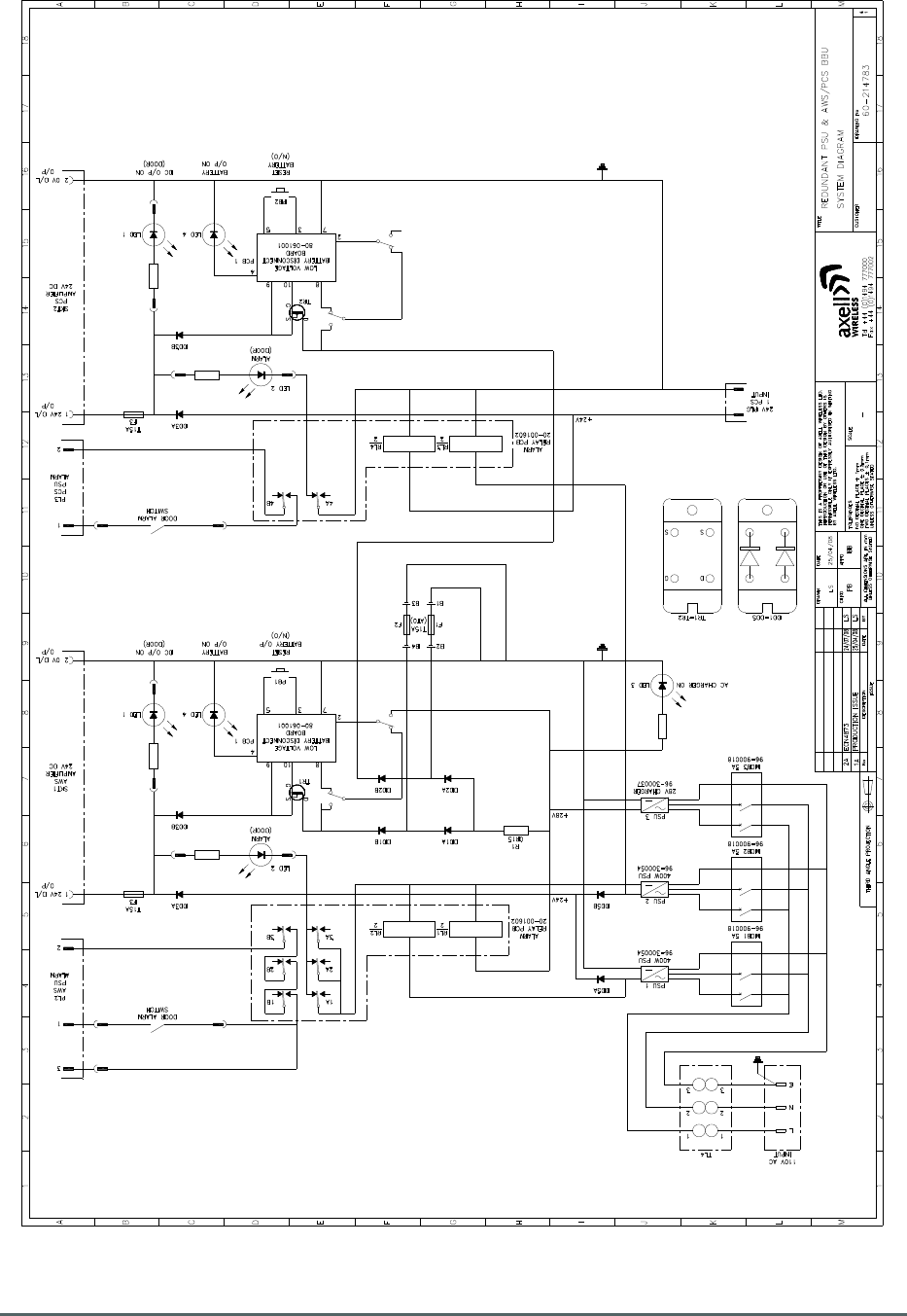
5.2. PSU and Battery Backup 60-214703 Circuit Diagram
Drawing Number 60-214783
Axell Wireless Limited
Technical Literature
Lincoln/Holland Upgrade Equipment
Document Number
60
-
214701HBKM
Issue No.
1
Date
29/08/2008
Page
27
of
43
5.3. PSU and Battery Backup 60-214703 External Features
A
Li
fting Handles **
B Lockable Door Handles
C Power and Alarm Indicators
D Wall Mounting Brackets
E Power and Alarm Ports see section 5.3.2. below
**Caution must be exercised when attempting to move or lift this unit when the batteries are installed,
the gross weight of the unit will be in excess of 70kg (155lbs)
Axell Wireless Limited
Technical Literature
Lincoln/Holland Upgrade Equipment
Document Number
60
-
214701HBKM
Issue No.
1
Date
29/08/2008
Page
28
of
43
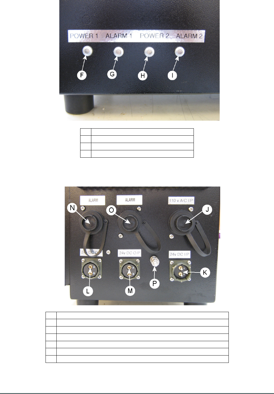
5.3.1. External LEDs
F Green LED “POWER 1” PSU 1*
G
Red LED “ALARM” PSU 1
H
Green LED “POWER 2” PSU 3*
I Red LED “ALARM” PSU 3
* See section 5.4. below
5.3.2. Power and Alarm Ports
J
AC Mains Input 110V
K 24V DC Input from Existing PSU 60-004002
L 24V DC Output to Remote Repeater 60-214701
M
24V DC Output to existing PCS Amplifier 60-004001
N “PSU 1” Alarm output to Remote Repeater 60-214701
O
“PSU 3” Alarm output to existing
PCS Amplifier 60
-
004001
P Earth Connection
Axell Wireless Limited
Technical Literature
Lincoln/Holland Upgrade Equipment
Document Number
60
-
214701HBKM
Issue No.
1
Date
29/08/2008
Page
29
of
43
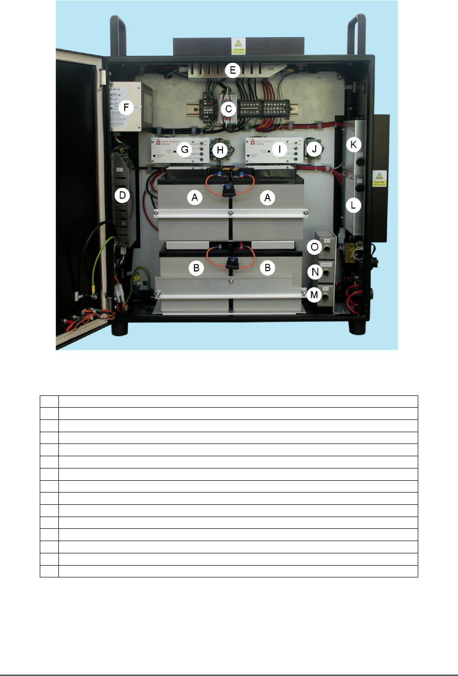
5.4. PSU and Battery Backup 60-214703 Internal Features
A Batteries 96-000004 “Pair 1”
B Batteries 96-000004 “Pair 2”
C Mains Filter 13-003302
D 400W PSU 96-300054 “PSU 1”
E 400W PSU 96-300054 “PSU 3”
F Charger PSU 96-300037 “PSU 2”
G
Charger Alarm Indicator Assembly 50-046937 for Batteries Pair 1
H 24V Relay Assembly 20-001602 for Batteries Pair 1
I Charger Alarm Indicator Assembly 50-046937 for Batteries Pair 2
J 24V Relay Assembly 20-001602 for Batteries Pair 2
K Power Combining Diodes and Fuse Assembly for DC Output from “PSU 1”
L Power Combining Diodes and Fuse Assembly for DC Output from “PSU 3”
M
Trip Switch for “PSU 1”
N Trip Switch for “PSU 2”
O
Trip Switch for “PSU 3”

Axell Wireless Limited
Technical Literature
Lincoln/Holland Upgrade Equipment
Document Number
60
-
214701HBKM
Issue No.
1
Date
29/08/2008
Page
30
of
43
5.5. PSU and Battery Backup 60-214703 Specification
PARAMETER SPECIFICATION
AC Supply Voltage
110V
DC Outputs
2 x 24V DC
DC Input (from 60
-
004002)
24V
Charging Current
< 6.0 Amps
Battery Output Voltage Set Level
23.5V ± 0.2V
Low Voltage Disconnect level
21.5V ± 0.5V
Alarms Fitted
(summary volt-free contacts)
PSU 1 Fail
PSU 2 Fail
Charger PSU Fail
Door Open
DC Input from 60-004002 Fail
Case Size (ex. handles and heatsinks)
620mm x 620mm x 250mm
Case Material
Aluminium Alloy (2mm)
Case Finish
Black Semi-gloss
Temperature Range
operation
-20
°
C to +60
°
C
storage
-40°C to +70°
Humidity
95% RHNC
5.6. PSU and Battery Backup 60-214703 Major Sub Components
Component
Part
Component Part Description Qty Per
Assembly
13-003302 Mains Filter 1
20-001602 24V Relay Assembly 2
50-046937 Charger Alarm Indicator Assembly 2
80-061001 Low Voltage Battery Disconnect Circuit 2
96-000004 38AH 12V Sealed Lead Acid Battery 4
96-300037 Charger PSU 1
96-300054 400W PSU 2
5.6.1. Batteries 96-000004
The batteries used in this arrangement are 38Ah 12V Sealed Lead Acid units and require no
maintenance.
General Specifications
Capacity
38 Ah
Chemical System
Lead
-
Acid
Dimensions (L x W x H)
197 mm x 165 mm x 170 mm
Internal Resistance
7.5 Milliohms
Maximum Operating Temperature
+50 °C (Charge)
+60 °C (Discharge)
Minimum Operating Temperature
-15 °C (Charge)
-20 °C (Discharge)
Nominal Voltage
12 V
Weight
14.2 kg
Life Expectancy
Standby Use
3 to 5 years
Cycle Use
(approx)
100% depth of discharge 250 cycles
50% depth of discharge 550 cycles
30% depth of discharge 1200 cycles

Axell Wireless Limited
Technical Literature
Lincoln/Holland Upgrade Equipment
Document Number
60
-
214701HBKM
Issue No.
1
Date
29/08/2008
Page
31
of
43
6. Installation – General Notes
6.1 General Remarks
When this equipment is initially commissioned, please use the equipment set-up record sheet in
Appendix B. This will help both the installation personnel and Axell Wireless should these figures be
needed for future reference or diagnosis.
The procedure for installing and commissioning an Axell Wall Mount Repeater is generally as follows:
1 Secure the Repeater in the chosen wall position.
2 Fix the antenna and connect its cables to the Repeater antenna ports.
3 Connect a suitable mains or battery power supply to the Repeater
4 Calculate the attenuation settings required for the uplink and the downlink paths, and set the
attenuators as described elsewhere in this document.
5 Switch the equipment mains on with the small switch located inside the Repeater on the lower
right hand side of the case.
6 If Base Station signals are available, make test calls via the Amplifier to ensure correct
operation, if possible monitoring the signal levels during these calls to ensure that the uplink
and downlink RF levels are as anticipated.
6.2 Electrical Connections
It is recommended that the electrical mains connection is made by a qualified electrician, who must be
satisfied that the supply will be the correct voltage and of sufficient capacity.
All electrical and RF connections should be completed and checked prior to power being applied for
the first time.
Ensure that connections are kept clean and are fully tightened.
6.3 RF Connections
Care must be taken to ensure that the correct connections are made with particular attention made to
the base station TX/RX ports. In the event that the base transmitter is connected to the RX output of
the equipment, damage to the equipment will be done if the base station transmitter is then keyed.
6.3.1. Termination of Unused Ports
In the event that any RF ports are unused (available for future expansion) these ports must be kept
terminated with the load terminations supplied by Axell for that purpose
Ensure that connections are kept clean and are fully tightened.
6.4 Optical Connections
The optical input and output ports will be shown in the system drawings. The ports are supplied with a
green plastic cover, which must be removed prior to the connection of the fibre cable. Ensure that
transmitter and receiver fibre cable are identified to prevent misconnection. At the master site, the
fibre transmitters are in the downlink path with the receivers in the uplink. At the remote sites the fibre
transmitters are in the uplink with the receivers in the downlink.
Always ensure that connections are kept clean and are fully tightened.

Axell Wireless Limited
Technical Literature
Lincoln/Holland Upgrade Equipment
Document Number
60
-
214701HBKM
Issue No.
1
Date
29/08/2008
Page
32
of
43
6.5 Commissioning
Once all connections are made the equipment is ready for commissioning.
To commission the system the test equipment detailed in Section 7.2. will be required.
Using the system diagrams and the end-to-end test specification (supplied with the equipment), the
equipment should be tested to ensure correct operation. Typical RF levels that are not listed in the
end-to-end specification, such as input levels to the fibre transmitters are detailed in the maintenance
section of this manual.
On initial power up the system alarm indicators on the front doors of the equipment should be
checked. A green LED on each unit with a power supply to it illuminates to indicate that the power
supply is connected to the unit. A red LED illuminated indicates a fault in that particular unit that must
be investigated before proceeding with the commissioning.
In the event that any part of the system does not function correctly as expected, check all connections
to ensure that they are to the correct port, that the interconnecting cables are not faulty and that they
are tightened. The majority of commissioning difficulties arise from problems with the interconnecting
cables and connectors.
6.6 Antenna Installation & Gain Calculations
A The equipment typically requires two (or as appropriate) antennas, one a highly directional
Yagi or similar directed towards the donor cell base station, and one a leaky feeder, omni-
directional antenna or Yagi to cover the area in which the mobiles are to be served.
B The maximum gain at which the equipment can be set is limited by the isolation that can be
achieved between these two antennas. Therefore when the antennas have been installed,
inject a signal (at a known power level) into one of them and measure the signal level received
by the other antenna on a spectrum analyser. The isolation can then be calculated as the
difference between these two figures. The gain in each path of the equipment should be set at
least 10 dB below this figure, using attenuators as described below in paragraph E.
C Also measure the received signal from the donor cell at the input to the equipment (base port).
The gain of the equipment downlink path should be set such the donor site will not overload
the equipment amplifiers. It is recommended that the input level should be less than -50dBm
at the input of the equipment (Base Port). (This figure is assuming maximum gain, and may be
increased by the value of the attenuator fitted in the downlink path.)
D Ensure that the mobile facing antenna has at least 70dB isolation from the nearest mobile.
(This is usually easily achieved when using a leaky feeder.)
E The equipment gain is set by setting the variable switched attenuators in each path (uplink and
downlink) refer to the photographs and layout drawings for the exact attenuator locations).
Note that the uplink (mobile to base) and downlink (base to mobile) path gains are set
independently. This allows the paths to have different gains if required to set the correct output
power levels.
F It is recommended that the gains are set such that the Downlink channel output levels from the
equipment are typically +30dBm per channel
(Input level + Gain = Output level).

Axell Wireless Limited
Technical Literature
Lincoln/Holland Upgrade Equipment
Document Number
60
-
214701HBKM
Issue No.
1
Date
29/08/2008
Page
33
of
43
7. Maintenance – General Notes
7.1. Fault Finding
7.1.1. Quick Fault Checklist
All tunnel equipment is individually tested to specification prior to despatch. Failure of this type of
equipment is not common. Experience has shown that a large number of fault conditions relating to
tunnel installations result from simple causes often occurring as result of transportation, unpacking
and installation. Below are listed some common problems which have resulted in poor performance or
an indicated non-functioning of the equipment.
• Mains power not connected or not switched on.
• External connectors not fitted or incorrectly fitted.
• Internal connectors becoming loose due to transport vibration.
• Wiring becoming detached as a result of heavy handling.
• Input signals not present due to faults in the antenna and feeder system.
• Base transmissions not present due to fault at the base station.
• Modems fitted with incorrect software configuration.
• Changes to channel frequencies and inhibiting channels.
• Hand held radio equipment not set to repeater channels.
• Hand held radio equipment not set to correct base station.
7.1.2 Fault Isolation
In the event that the performance of the system is suspect, a methodical and logical approach to the
problem will reveal the cause of the difficulty. The System consists of modules fitted in enclosed
shelves within a rack mounted, environmentally protected enclosure.
Transmissions from the main base stations are passed though the system to the mobile radio
equipment; this could be a handheld radio or a transceiver in a vehicle. This path is referred to as the
downlink. The return signal path from the mobile radio equipment to the base station is referred to as
the uplink.
The first operation is to check the alarms of each of the active units and determine that the power
supplies to the equipment are connected and active.
This can be achieved remotely (via CEMS, the RS232 Coverage Enhancement Management System,
if fitted), or locally with the front panel LED’s. The green LED on the front panel should be illuminated,
while the red alarm indicator should be off. If an Alarm is on, then that individual shelf must be
isolated and individually tested against the original test specification.
The individual amplifier units within the shelf have a green LED showing through a hole in their piggy-
back alarm board, which is illuminated if the unit is working correctly. If an amplifier is suspect, check
the DC power supply to the unit. If no other fault is apparent use a spectrum analyser to measure the
incoming signal level at the input and then after reconnecting the amplifier input, measure the output
level. Consult with the system diagram to determine the expected gain and compare result.
In the event that there are no alarms on and all units appear to be functioning it will be necessary to
test the system in a systematic manner to confirm correct operation.

Axell Wireless Limited
Technical Literature
Lincoln/Holland Upgrade Equipment
Document Number
60
-
214701HBKM
Issue No.
1
Date
29/08/2008
Page
34
of
43
7.1.3 Downlink
Confirm that there is a signal at the expected frequency and strength from the base station. If this is
not present then the fault may lay outside the system. To confirm this, inject a downlink frequency
signal from a known source at the master site BTS input and check for output at the remote site
feeder output.
If a signal is not received at the output it will be necessary to follow the downlink path through the
system to find a point at which the signal is lost. The expected downlink output for the given input can
be found in the end-to-end test specification.
7.1.4 Uplink
Testing the uplink involves a similar procedure to the downlink except that the frequencies used are
those transmitted by the mobile equipment.
7.1.5 Fibre Optics
The Fibre Optic transmitters and receivers both have two LED status indicators, one on each module
showing DC power and the other indicating ‘Laser On’ for the transmitter, and ‘Carrier Being
Received’ for the receiver. Assuming that all of the indicators are illuminated, it will be necessary to
check the RF inputs and outputs to the fibre optic units.
Typically the input to transmitter units will be at a level of between -30 and -15 dBm. The RF gain of a
pair (TX to RX) units is factory set to give a 0dB gain, but this is with a short, low loss fibre. In
determining the performance of the link, the insertion loss of the fibre and any power splitters fitted
must be considered. A general rule of thumb figure would be around 0.5 - 1.5dB loss per Kilometre.
7.1.7 Checking service
Following the repair of any part of the system it is recommended that a full end-to-end test is carried
out in accordance with the test specification and that the coverage is checked by survey.
It is important to bear in mind that the system includes a radiating cable network and base stations
that may be faulty or may have been damaged.
7.1.8 Fault repair
Once a faulty component has been identified, a decision must be made on the appropriate course to
carry out a repair. A competent engineer can quickly remedy typical faults such as faulty connections
or cables. The exceptions to this are cable assemblies connecting bandpass filter assemblies that are
manufactured to critical lengths to maintain a 50-ohm system.
Care should be taken when replacing cables or connectors to ensure that items are of the correct
specification. The repair of component modules such as amplifiers and bandpass filters will not
usually be possible in the field, as they frequently require specialist knowledge and test equipment to
ensure correct operation. It is recommended that items of this type are replaced with a spare unit and
the faulty unit returned to Axell Wireless for repair.

Axell Wireless Limited
Technical Literature
Lincoln/Holland Upgrade Equipment
Document Number
60
-
214701HBKM
Issue No.
1
Date
29/08/2008
Page
35
of
43
7.1.9 Service Support
Advice and assistance with maintaining and servicing this system are available by contacting
Axell Wireless Ltd., see section 2.7.
NOTE
Individual modules are not intended to be repaired on site and attempts at repair will
invalidate active warranties. Company policy is that individual modules should be repaired
by replacement. Axell Wireless Ltd. maintains a level of stock of most modules which can
usually be despatched at short notice to support this policy.
7.2 Tools & Test Equipment
The minimum tools and test equipment needed to successfully service this Axell Wireless product
are as follows:-
Spectrum analyser 100kHz to 2GHz (Dynamic range = 90dB).
Signal Generator 30MHz to 2GHz (-120dBm to 0dBm o/p level).
Attenuator 20dB, 10W, DC-2GHz, (N male – N female).
Test Antenna Yagi or dipole for operating frequency.
Optical Power Meter 1300 – 1560nM (-40 - +10dB)
Digital multi-meter Universal Volt-Ohm-Amp meter.
Test cable x 2
N male
–
N male, 2M long RG214.
Test cable x 2 SMA male – N male, 1m long RG223.
Hand tools Philips #1&2 tip screwdriver.
3mm flat bladed screwdriver.
SMA spanner and torque setter.
7.3 Care of Modules
7.3.1 General Comments
Many of the active modules contain semiconductor devices utilising MOS technology, which can be
damaged by electrostatic discharge. Correct handling of such modules is mandatory to ensure their
long-term reliability.
To prevent damage to a module, it must be withdrawn and inserted with care. The module may have
connectors on its underside, which might not be visible to the service operative.
7.3.2 Module Removal (LNAs, general procedure):
The following general instructions should be followed to remove a module:
1 Remove power to the unit
2 Remove all visible connectors (RF, DC & alarm)
3 Release module retaining screws.
4 Slowly but firmly, pull the module straight out of its position. Take care not to twist/turn the
module during withdrawal. (When the module is loose, care may be needed, as there may be
concealed connections underneath).

Axell Wireless Limited
Technical Literature
Lincoln/Holland Upgrade Equipment
Document Number
60
-
214701HBKM
Issue No.
1
Date
29/08/2008
Page
36
of
43
7.3.3 Module Replacement (general):
1 Carefully align the module into its location then slowly push the module directly straight into its
position, taking care not to twist/turn it during insertion.
2 Reconnect all connectors, RF, alarm, power etc., (concealed connectors may have to be
connected first).
3 Replace retaining screws (if any).
4 Double-check all connections before applying power.
7.3.4 Power Amplifiers
1) Remove power to the unit. (Switch off at mains/battery, or remove DC in connector)
2) Remove alarm wires from alarm screw terminal block or disconnect multi-way alarm
connector.
3) Carefully disconnect the RF input and output coaxial connectors (usually SMA)
If alarm board removal is not required, go to step 5.
4) There is (usually) a plate attached to the alarm board which fixes it to the amplifier, remove its
retaining screws and the alarm board can be withdrawn from the amplifier in its entirety. On
certain types of amplifier the alarm board is not mounted on a dedicated mounting plate; in this
case it will have to firstly be removed by unscrewing it from the mounting pillars, in most
cases, the pillars will not have to be removed before lifting the amplifier.
5) If the amplifier to be removed has a heatsink attached, there may be several different ways it
can have been assembled. The most commonly used method, is screws through the front of
the heatsink to threaded screw holes (or nuts and bolts), into the amplifier within the main
case. If the heatsink is mounted on the rear of the main case (e.g., against a wall in the case
of wall mounted enclosures), then the fixing method for the heatsink will be from within the
case, (otherwise the enclosure would have to be removed from the wall in order to remove the
heatsink).
When the heatsink has been removed, the amplifier may be unscrewed from the main casing by its
four corner fixings and gently withdrawn.
Fitting a new power amplifier module will be the exact reverse of the above.
Note: Do not forget to apply fresh heatsink compound to the heatsink/main case joint and also
between the amplifier and the main case.
7.3.5 Low Power Amplifier Replacement
• Disconnect the mains power supply and disconnect the 24V dc supply connector for the LPA.
• Disconnect the RF input and output cables from the LPA.
• Disconnect the alarm connector.
• Remove the alarm monitoring wires from (D type connector) pins 9 and 10.
• Remove the LPA module by removing the four retaining screws, replace with a new LPA
module and secure it with the screws.
• Connect the RF cables to the LPA input and output connectors. Reconnect the wires to the
alarm board connector pins 9 and 10.
• Reconnect the DC supply connector and turn the mains switch on.

Axell Wireless Limited
Technical Literature
Lincoln/Holland Upgrade Equipment
Document Number
60
-
214701HBKM
Issue No.
1
Date
29/08/2008
Page
37
of
43
Note: Tighten SMA connectors using only a dedicated SMA torque spanner. If SMA connectors are
over-tightened, irreparable damage will occur. Do not use adjustable pliers to loosen/tighten SMA
connectors.
Also take care not to drop or knock the module as this can damage (or misalign in the case of tuned
passive modules) sensitive internal components. Always store the modules in an environmentally
friendly location
7.3.6 Module Transportation:
To maintain the operation, performance and reliability of any module it must be stored and
transported correctly. Any module not installed in a whole system must be kept in an anti-static bag or
container. These bags or containers are normally identified by being pink or black, and are often
marked with an ESD label. Any module sent back to Axell Wireless for investigation/repair must be so
protected. Please contact the Axell Wireless quality department before returning a module, see
section 2.7.

Axell Wireless Limited
Technical Literature
Lincoln/Holland Upgrade Equipment
Document Number
60
-
214701HBKM
Issue No.
1
Date
29/08/2008
Page
38
of
43
Appendix A
A.1. Glossary of Terms used in this document
Repeater or
Cell Enhancer
A Radio Frequency (RF) amplifier which can simultaneously
amplify and re-broadcast Mobile Station (MS) and Base
Transceiver Station (BTS) signals.
Band Selective
Repeater
A Cell Enhancer designed for operation on a range of channels
within a specified frequency band.
Channel Selective
Repeater
A Cell Enhancer, designed for operation on specified channel(s)
within a specified frequency band. Channel frequencies may be
factory set or on
-
site programmable.
AC
Alternating Current
AGC
Automatic Gain Control
BBU
Battery Backup Unit
BTS
Base Transceiver Station
CEMS Coverage Enhanced Management System
C/NR Carrier-to-Noise Ratio
DC Direct Current
Downlink (D/L) RF signals TX from the BTS to the Master Site
FO Fibre Optic
GND Ground
ID Identification Number
LED Light Emitting Diode
LNA Low Noise Amplifier
LPA Low Power Amplifier
MOU Master Optical Unit
M.S. Mobile Station
MTBF Mean Time Between Failures
N/A Not Applicable
N/C No Connection
OFR On Frequency Repeater
OIP3 Output Third Order Intercept Point
P1dB 1dB Compression Point
PA Power Amplifier
RF Radio Frequency
RSA Receiver/Splitter Amplifier
RX Receiver
S/N Serial Number
TX Transmitter
Uplink (U/L) RF signals transmitted from the MS to the BTS
VSWR Voltage Standing Wave Ratio
WDM Wave division multiplex
Axell Wireless Limited
Technical Literature
Lincoln/Holland Upgrade Equipment
Document Number
60
-
214701HBKM
Issue No.
1
Date
29/08/2008
Page
39
of
43
90-000001
AA
NTS
PL 10/05/00
AFL - STANDARD SYMBOLS
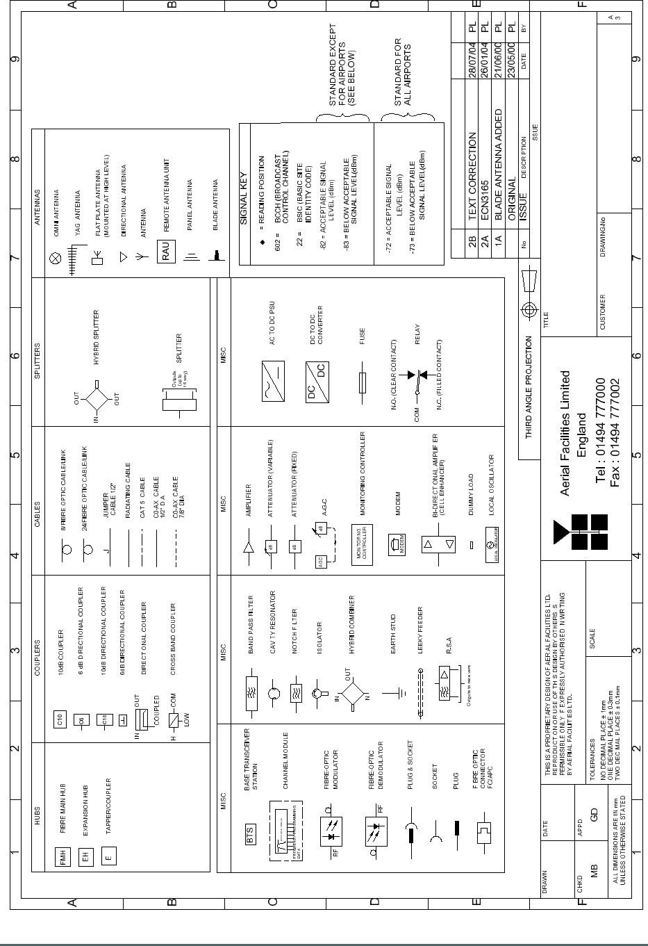
A.2. Key to Drawing Symbols used in this document

Axell Wireless Limited
Technical Literature
Lincoln/Holland Upgrade Equipment
Document Number
60
-
214701HBKM
Issue No.
1
Date
29/08/2008
Page
40
of
43
A.3. EC Declaration of Conformity
In accordance with BS EN ISO/IEC 17050-1&-2:2004
Axell Wireless Limited
Aerial House
Asheridge Road
Chesham
Buckinghamshire HP5 2QD
United Kingdom
DECLARES, UNDER OUR SOLE RESPONSIBILITY THAT THE FOLLOWING PRODUCT:
PRODUCT PART No. AND DESCRIPTION
60-214702 Tri-Band Cable Signal Combiner
60-214701 Fibre Fed Remote Repeater
60-214703 Redundant PSU + Battery Backup
IN ACCORDANCE WITH THE FOLLOWING DIRECTIVES:
1999/5/EC The Radio & Telecommunications Terminal Equipment Directive Annex V
and its amending directives
HAS BEEN DESIGNED AND MANUFACTURED TO THE FOLLOWING STANDARD[S] OR
OTHER NORMATIVE DOCUMENT[S]:
BS EN 60950 Information technology equipment.
Safety. General requirements
ETS EN 301 489-1 EMC standard for radio equipment and services.
Part 1. Common technical requirements
I hereby declare that the equipment named above has been designed to comply with the relevant
sections of the above referenced specifications. The unit complies with all essential requirements
of the Directives.
SIGNED
B. S. Barton
Operations Director DATE: 24/06/2008
Registered Office: Aerial House, Asheridge Road, Chesham, Buckinghamshire, HP5 2QD England Registered No. 4042808 (England)
www.axellwireless.com

Axell Wireless Limited
Technical Literature
Lincoln/Holland Upgrade Equipment
Document Number
60
-
214701HBKM
Issue No.
1
Date
29/08/2008
Page
41
of
43
A.4. Waste Electrical and Electronic Equipment (WEEE) Notice
The Waste Electrical and Electronic Equipment (WEEE) Directive became law in
most EU countries during 2005. The directive applies to the disposal of waste
electrical and electronic equipment within the member states of the European
Union.
As part of the legislation, electrical and electronic equipment will feature the
crossed out wheeled bin symbol (see image at left) on the product or in the
documentation to show that these products must be disposed of in accordance
with the WEEE Directive.
In the European Union, this label indicates that this product should not be disposed of with domestic
or "ordinary" waste. It should be deposited at an appropriate facility to enable recovery and recycling.

Axell Wireless Limited
Technical Literature
Lincoln/Holland Upgrade Equipment
Document Number
60
-
214701HBKM
Issue No.
1
Date
29/08/2008
Page
42
of
43
A.5. Document Amendment Record
Issue
No.
Date Incorporated
by
Section
Amended
Reason for new issue
A 11 June 2008 AJS Draft
B 29 July 2008 AJS 3.2. Preliminary Issue
1 29 August 2008 AJS 3.2. Issue

Axell Wireless Limited
Technical Literature
Lincoln/Holland Upgrade Equipment
Document Number
60
-
214701HBKM
Issue No.
1
Date
29/08/2008
Page
43
of
43
Appendix B
B.1 Initial Equipment Set-Up Calculations
General Information
Site Name:
Client Name:
Date:
AWL Equip. Model No.
Antenna Systems
Model Gain Azimuth Comments
A
-
Service Antenna
B – Donor Antenna
Type Loss Length Comments
C – Service Feeder
D – Donor Feeder
Initial Parameters
E – CE Output Power dBm
F – Antenna Isolation dB
G – Input signal level from donor BTS dBm
Operating Voltage V
Downlink Calculations
Parameter
Comments
Value
Input signal level (G) dBm
CE max. o/p power (E)
dBm
Gain setting E - G dB
Isolation required
(Gain + 10dB)
dB
Service antenna gain (A) dB
Service antenna feeder loss (C) dB
Effective radiated power (ERP) E+A-C dBm
Attenuator setting CE gain-gain setting dB
If the input signal level in the uplink path is known and steady, use the following calculation table to
determine the gain setting. If the CE features Automatic Gain Control the attenuator should be set to
zero and if not, then the attenuation setting for both uplink and downlink should be similar.
Uplink Calculations
Parameter Comments Value
Input signal level dBm
CE max. o/p power (E) dBm
Gain setting
dB
Required isolation dB
Donor antenna gain (B)
dB
Donor antenna feeder loss (D) dB
Effective radiated power (ERP) E+B-D dBm
Attenuator setting (CE gain-gain setting) dB