PBE Europe as Axell Wireless 60-274901 60-274901 Fibre Feed Amplifier User Manual Manual
Axell Wireless 60-274901 Fibre Feed Amplifier Manual
Manual

Axell Wireless Limited
Technical Literature
Fiber Optic, Uplink, Band Selective,
VHF Booster Amplifier
Document Number
60
-
274901HBK
Issue No. 2
Date 13/06/2011
Page
1
of
16
Fiber Optic, Uplink, Band Selective,
VHF Booster Amplifier
User Handbook
For
GETS Global Signalling L.L.C.
AWL Works Order Q122997
AWL Product Part No. 60-274901
Axell Wireless Limited
Head Office: Aerial House, Asheridge Road, Chesham, Buckinghamshire, HP5 2QD, United Kingdom
Tel: + 44 (0) 1494 777000 Fax: + 44 (0) 1494 777002
info@axellwireless.com www.axellwireless.com

Axell Wireless Limited
Technical Literature
Fiber Optic, Uplink, Band Selective,
VHF Booster Amplifier
Document Number
60
-
274901HBK
Issue No. 2
Date 13/06/2011
Page
2
of
16
Table of Contents
1.
Introduction ................................................................................................................................ 3
1.1.
Scope and Purpose of Document ........................................................................................ 3
1.2.
Limitation of Liability Notice.................................................................................................. 3
2.
Safety Considerations................................................................................................................ 4
2.1.
Earthing of Equipment ......................................................................................................... 4
2.2.
Electric Shock Hazard .......................................................................................................... 4
2.3.
RF Radiation Hazard ........................................................................................................... 4
2.4.
Lifting and other Health and Safety Recommendations ........................................................ 4
2.5.
Chemical Hazard ................................................................................................................. 5
2.6.
Laser Safety ........................................................................................................................ 5
2.7.
Emergency Contact Numbers .............................................................................................. 5
3.
Equipment Overview ................................................................................................................. 6
3.1.
List of Major Sub-Components ............................................................................................. 7
3.2.
Specification ........................................................................................................................ 8
3.3.
Circuit Schematic ................................................................................................................. 9
3.4.
Case Front View ................................................................................................................ 10
3.5.
Case Rear View ................................................................................................................. 11
3.6.
Local Alarm Output Schematic ........................................................................................... 12
Appendix A ........................................................................................................................................ 13
A.1.
Glossary of Terms used in this document .......................................................................... 13
A.2.
Key to Drawing Symbols used in this document ................................................................. 14
A.4.
Waste Electrical and Electronic Equipment (WEEE) Notice ............................................... 15
A.5.
Document Amendment Record .......................................................................................... 16

Axell Wireless Limited
Technical Literature
Fiber Optic, Uplink, Band Selective,
VHF Booster Amplifier
Document Number
60
-
274901HBK
Issue No. 2
Date 13/06/2011
Page
3
of
16
1. Introduction
1.1. Scope and Purpose of Document
This handbook is for use solely with the equipment identified by the Axell Wireless Limited (AWL) Part
Number shown on the front page. It is not to be used with any other equipment unless specifically
authorised by AWL. This is a controlled release document and, as such, becomes a part of the Axell
Wireless Total Quality Management System. Alterations and modification may therefore only be
performed by Axell Wireless.
AWL recommends that the installer of this equipment familiarise themselves with the safety and
installation procedures contained within this document before installation commences.
The purpose of this handbook is to provide the user/maintainer with sufficient information to service
and repair the equipment to the level agreed. Maintenance and adjustments to any deeper level must
be performed by AWL, normally at the company’s repair facility in Chesham, England.
This handbook has been prepared in accordance with BS 4884, and AWL’s Quality procedures, which
maintain the company’s registration to BS EN ISO 9001:2000 and to the R&TTE Directive of the
European Parliament. Copies of the relevant certificates and the company Quality Manual can be
supplied on application.
This document fulfils the relevant requirements of Article 6 of the R&TTE Directive.
1.2. Limitation of Liability Notice
This manual is written for the use of technically competent operators/service persons. No liability is
accepted by AWL for use or misuse of this manual, the information contained therein, or the
consequences of any actions resulting from the use of the said information, including, but not limited
to, descriptive, procedural, typographical, arithmetical, or listing errors.
Furthermore, AWL does not warrant the absolute accuracy of the information contained within this
manual, or its completeness, fitness for purpose, or scope.
AWL has a policy of continuous product development and enhancement, and as such, reserves the
right to amend, alter, update and generally change the contents, appearance and pertinence of this
document without notice.
Unless specified otherwise, all AWL products carry a twelve month warranty from date of shipment.
The warranty is expressly on a return-to-base repair or exchange basis and the warranty cover does
not extend to on-site repair or complete unit exchange.
Axell Wireless Limited
Technical Literature
Fiber Optic, Uplink, Band Selective,
VHF Booster Amplifier
Document Number
60
-
274901HBK
Issue No. 2
Date 13/06/2011
Page
4
of
16
2. Safety Considerations
2.1. Earthing of Equipment
Equipment supplied from the mains must be connected to grounded outlets and earthed
in conformity with appropriate local, national and international electricity supply and
safety regulations.
2.2. Electric Shock Hazard
The risk of electrical shocks due to faulty mains driven power supplies whilst
potentially ever present in any electrical equipment, would be minimised by adherence
to good installation practice and thorough testing at the following stages:
a) Original assembly.
b) Commissioning.
c) Regular intervals, thereafter.
All test equipment must be in good working order prior to its use. High current power supplies can be
dangerous because of the possibility of substantial arcing. Always switch off during disconnection and
reconnection.
2.3. RF Radiation Hazard
RF radiation, (especially at UHF frequencies) arising from transmitter outputs
connected to AWL’s equipment, must be considered a safety hazard.
This condition might only occur in the event of cable disconnection, or because a
‘spare’ output has been left un-terminated. Either of these conditions would impair the
system’s efficiency. No investigation should be carried out until all RF power sources have been
removed. This would always be a wise precaution, despite the severe mismatch between the
impedance of an N type connector at 50Ω, and that of free space at 377Ω, which would severely
compromise the efficient radiation of RF power. Radio frequency burns could also be a hazard, if any
RF power carrying components were to be carelessly touched!
Antenna positions should be chosen to comply with requirements (both local & statutory) regarding
exposure of personnel to RF radiation. When connected to an antenna, the unit is capable of
producing RF field strengths, which may exceed guideline safe values especially if used with
antennas having appreciable gain. In this regard the use of directional antennas with backscreens
and a strict site rule that personnel must remain behind the screen while the RF power is on, is
strongly recommended.
Where the equipment is used near power lines or in association with temporary masts not having
lightning protection, the use of a safety earth connected to the case-earthing bolt is strongly advised.
2.4. Lifting and other Health and Safety Recommendations
Certain items of AWL equipment are heavy and care should be taken when lifting
them by hand. Ensure that a suitable number of personnel, appropriate lifting
apparatus and appropriate personal protective equipment is used especially when
installing Equipment above ground e.g. on a mast or pole and manual handling
precautions relevant to items of the weight of the equipment being worked on must be
observed at all times when handling, installing or dismounting this equipment.
Axell Wireless Limited
Technical Literature
Fiber Optic, Uplink, Band Selective,
VHF Booster Amplifier
Document Number
60
-
274901HBK
Issue No. 2
Date 13/06/2011
Page
5
of
16
2.5. Chemical Hazard
Beryllium Oxide, also known as Beryllium Monoxide, or Thermalox™, is sometimes
used in devices within equipment produced by Axell Wireless Ltd. Beryllium oxide dust
can be toxic if inhaled, leading to chronic respiratory problems. It is harmless if
ingested or by contact.
Products that contain beryllium are load terminations (dummy loads) and some power amplifiers.
These products can be identified by a yellow and black “skull and crossbones” danger symbol (shown
above). They are marked as hazardous in line with international regulations, but pose no threat under
normal circumstances. Only if a component containing beryllium oxide has suffered catastrophic
failure, or exploded, will there be any danger of the formation of dust. Any dust that has been created
will be contained within the equipment module as long as the module remains sealed. For this reason,
any module carrying the yellow and black danger sign should not be opened. If the equipment is
suspected of failure, or is at the end of its life-cycle, it must be returned to Axell Wireless Ltd. for
disposal.
To return such equipment, please contact the Operations Support Department, who will give you a
Returned Materials Authorisation (RMA) number. Please quote this number on the packing
documents, and on all correspondence relating to the shipment.
Polytetrafluoroethylene, (P.T.F.E.) and P.T.F.E. Composite Materials
Many modules/components in AWL equipment contain P.T.F.E. as part of the RF insulation barrier.
This material should never be heated to the point where smoke or fumes are evolved. Any person
feeling drowsy after coming into contact with P.T.F.E., especially dust or fumes should seek medical
attention.
2.6. Laser Safety
General good working practices adapted from
EN60825-2: 2004/ EC 60825-2:2004
Do not stare with unprotected eyes or with any unapproved optical device at the fiber
ends or connector faces or point them at other people, Use only approved filtered or
attenuating viewing aids.
Any single or multiple fiber end or ends found not to be terminated (for example, matched, spliced)
shall be individually or collectively covered when not being worked on. They shall not be readily
visible and sharp ends shall not be exposed.
When using test cords, the optical power source shall be the last connected and the first
disconnected; use only approved methods for cleaning and preparing optical fibers and optical
connectors.
Always keep optical connectors covered to avoid physical damage and do not allow any dirt/foreign
material ingress on the optical connector bulkheads.
The optical fiber jumper cable minimum bend radius is 3cm; bending to a smaller radius may result in
optical cable breakage and excessive transmission losses.
Caution: The FO units are NOT weather proof.
2.7. Emergency Contact Numbers
The Axell Wireless Network Services Support Desk can be contacted on:
Telephone +44 (0)1494 777747
Fax. +44 (0)1494 777002
e-mail support@axellwireless.com

Axell Wireless Limited
Technical Literature
Fiber Optic, Uplink, Band Selective,
VHF Booster Amplifier
Document Number
60
-
274901HBK
Issue No. 2
Date 13/06/2011
Page
6
of
16
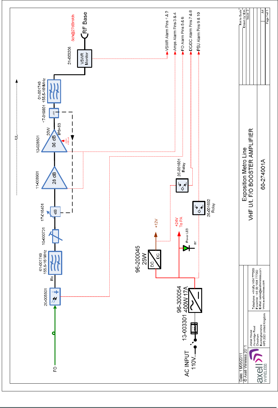
3. Equipment Overview
Fiber Optic, Uplink, Band Selective, VHF Booster Amplifier Part Number 60-274901 is built into an
8U, 19” rack mount shelf. The amplifier is used to filter and amplify the signal levels of one VHF band,
155.5MHz to 161.0MHz; in the Uplink direction only.
The Uplink Optical signal is received from Fiber Optic Transmitter Part Number 60-275101 via Fiber
Optic cable at the FC/APC port labelled “F/O” (annotated “A” in 3.4.); the optical Uplink signal then
enters Fiber Optic RX Module 20-005501 which demodulates the Optical signal to RF.
The RF signal then passes through a Bandpass Filter 01-001749 tuned to pass the Uplink band and
to reject out-of-band noise; after leaving the Bandpass filter the Uplink signal passes through the
Variable Switched Attenuator 10-000701 which can introduce up to 30dB of signal attenuation if
required. The attenuator is controlled by a set of four toggle switches (annotated “E” in section 3.5.)
on the front panel of the Amplifier shelf; each switch is clearly marked with the attenuation it provides,
and the total attenuation in-line is the sum of the values switched in.
After leaving the switched attenuator the Uplink signal passes first through the AGC Attenuator
Module 17-016401 (which is controlled by AGC Detector Module 17-019801 fitted further on in the RF
path) and then through a Low Noise Amplifier 11-008901 which provides 28dB of gain.
The Low Noise Amplifier is followed by a 20W Power Amplifier 12-028501 which provides 36dB of
gain and then the Uplink signal passes through the AGC Detector Module 17-019801 which regulates
the gain level by adjusting AGC Attenuator Module 17-016401.
The AGC Detector Module monitors the RF level being delivered by the power amplifier, and when a
certain threshold is reached it begins to increase the value of the AGC Attenuator Module to limit the
RF output to the (factory set) threshold. Therefore overloading of the power amplifier is avoided.
After passing through the AGC Detector Module the Uplink path passes through a second Bandpass
Filter 01-001749 to further reject out-of-band noise and then through VSWR Monitor 21-003207.
Upon leaving the VSWR Monitor the Uplink signal exits the Amplifier shelf for the Uplink Antenna
System via the N type port labelled “RF Base” (annotated “F” in section 3.5.).
The Amplifier is powered from mains AC at 110V which drives an internal 400W PSU module
providing 24V DC for the power amplifier; a DC/DC converter provides 12V DC for the remaining
active modules.
The Amplifier has an alarm system; both of the amplifier modules, the PSU, DC/DC converter, the
F/O RX and the VSWR Monitor modules carry their own voltage-free, dry contact alarm relay outputs
which are summed at the 15 way “D” alarm output connector on the rear of the case (annotated “L” in
section 3.5.).

Axell Wireless Limited
Technical Literature
Fiber Optic, Uplink, Band Selective,
VHF Booster Amplifier
Document Number
60
-
274901HBK
Issue No. 2
Date 13/06/2011
Page
7
of
16
3.1. List of Major Sub-Components
Component
Part
Part Description Qty Per
Assembly
01
-
001749
Bandpass Filter
2
10-000701 Variable Switched Attenuator 0-30dB 1
11
-
008901
Low Noise Amplifier
28dB
1
12-028501 20W Power Amplifier 36dB 1
13-003301 Mains Filter Assembly 1
17-016401 AGC Attenuator Module 1
17-019801 AGC Detector Module 1
20
-
001601
12V Dual Relay Assembly
3
20-001602 24V Dual Relay Assembly 1
20
-
005501
Fiber Optic RX Module
1
21-003207 VSWR Monitor 1
96-200045 DC/DC Converter 24V in/12V out 1
96-300054 400W PSU Module 1
91-520003 Switchd/Fused Mains Inlet 1

Axell Wireless Limited
Technical Literature
Fiber Optic, Uplink, Band Selective,
VHF Booster Amplifier
Document Number
60
-
274901HBK
Issue No. 2
Date 13/06/2011
Page
8
of
16
3.2. Specification
Electrical
Uplink Frequency Range
155.5MHz to 161.0MHz
Bandwidth
5.5 MHz Typical
Passband Ripple
± 1.5dB
Uplink Power
Amplifier
20W
Uplink PA IP3
+53 dBm
Uplink Output Power
+27 dBm/carrier
No. of F/O ports
1 FC/APC
Gain
30-60 dB
Gain Adjust
0-30dB in 1dB Steps
VSWR
1.5:1
Impedance
50 Ohms
Uplink Noise Figure
< 6dB (at maximum gain)
AGC
30dB Dynamic Range
Power Supply
220VAC or 110VAC
Power Consumption
< 300 Watts
Environmental/Mechanical
Operating Temperature
-25°C to 55°C
Storage Temperature
-
30°C to 70°C
Cooling
Convection
Humidity
95% RHNC
Mechanical
19” rack, 8U
Dimensions
W483mm x D400mm x H360mm
Weight
< 25kg
RF Connectors
N-Type Female
Battery Back Up
N/A
Alarm Interfaces
Local
Axell Wireless Limited
Technical Literature
Fiber Optic, Uplink, Band Selective,
VHF Booster Amplifier
Document Number
60
-
274901HBK
Issue No. 2
Date 13/06/2011
Page
9
of
16
3.3. Circuit Schematic
Axell Wireless Limited
Technical Literature
Fiber Optic, Uplink, Band Selective,
VHF Booster Amplifier
Document Number
60
-
274901HBK
Issue No. 2
Date 13/06/2011
Page
10
of
16
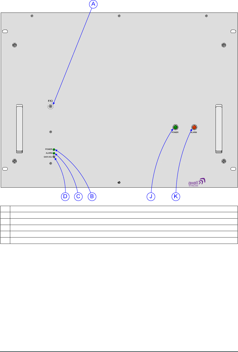
3.4. Case Front View
A FC/APC Optical connector “F/O”, VHF Optical Uplink input from F/O Transmitter, 60-275101
B Green LED “POWER”, Fiber Optic RX Power On indicator, illuminated during normal operation
C Green LED “ALARM”, Fiber Optic RX Alarm indicator, extinguished during alarm state
D Fiber Optic RX RF gain adjustment
J Green LED “POWER”, illuminated during normal operation
K Red LED “ALARM”, illuminated during alarm condition
Axell Wireless Limited
Technical Literature
Fiber Optic, Uplink, Band Selective,
VHF Booster Amplifier
Document Number
60
-
274901HBK
Issue No. 2
Date 13/06/2011
Page
11
of
16
LOCAL ALARMS
A/C INPUT 110V
FUSE T3.15A
RF BASE
REF. 60-274901
Desc.
U/L Freq:
DATE:
S/N
E F
I GH N
L
VSWR MONITOR
M
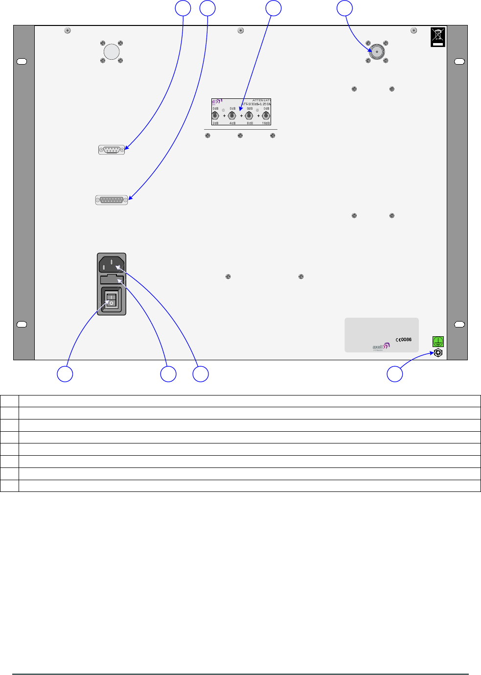
3.5. Case Rear View
E Variable Switched Attenuator 0-30dB, 10-000701
F N type port “RF BASE”, VHF RF U/L O/P to U/L antenna system
G
AC Input, 110V
H AC Input on/off switch
I Location of fuse for AC input
L 15 Way “D” panel plug “LOCAL ALARMS”, volt free, dry contact alarm output.
(1)
M
9 Way “D” panel socket “VSWR MONITOR”, RS232 port for VSWR Monitor configuration
(2)
N Earthing connection
(1)
See section 3.6. below
(2)
Not user configurable
Axell Wireless Limited
Technical Literature
Fiber Optic, Uplink, Band Selective,
VHF Booster Amplifier
Document Number
60
-
274901HBK
Issue No. 2
Date 13/06/2011
Page
12
of
16
Date: 10 June 2011
© AWL 2011
1
9
1
9
1
5
A1 A2 1
5
A1 A2
LA EXPO Uplink Booster Amplifier Shelves
Alarm Wiring Schematic
Aerial House
Asheridge Road
Chesham
Buckinghamshire
HP5 2QD United Kingdom
Telephone: +44 (0) 1494 777000
Facsimile: +44 (0) 1494 777002
E-Mail: info@axellwireless.com
www.axellwireless.com
0V
12V
LOW NOISE/POWER
AMPLIFIER VSWR MONITORPOWER AMPLIFIER
0V
FO RECIEVER
24V
0V
24V
0V
0V 24V 0V 24V
20-001602
0V 12V 0V 12V
20-001601
0V 12V 0V 12V
20-001601
12V 12V 12V 12V
0V 12V 0V 12V
20-001601
0V 12V
From +VE
DC-DC Converter
FROM +VE
POWER SUPPLY
0V
TO -VE ALARM LED
ON FRONT PANEL
18
9 15
15 way “D” panel plug
on front panel View on mating face
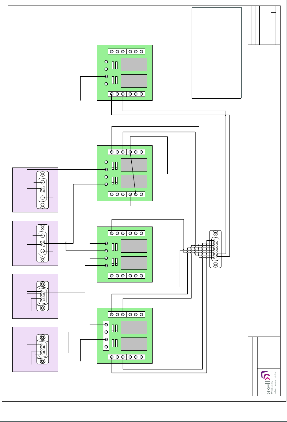
ALARM OUTPUTS
VOLT FREE CONTACTS
OPEN=FAIL , CLOSED= GOOD
PINS 1 & 2 VSWR ALARM
PINS 3 & 4 AMPLIFIER ALARM
PINS 5 & 6 FO ALARM
PINS 7 & 8 DC-DC CONVERTOR ALARM
PINS 9 & 10 PSU ALARM
COM
N/C
N/O
COM
N/C
N/O
COM
N/C
N/O
COM
N/C
N/O
COM
N/C
N/O
COM
N/C
N/O
COM
N/C
N/O
COM
N/C
N/O
COM
N/C
N/O
COM
N/C
N/O
COM
N/C
N/O
COM
N/C
N/O
COM
N/C
N/O
COM
N/C
N/O
COM
N/C
N/O
COM
N/C
N/O
Page 1 of 1
A3
Issue: 3
Drawn by: PLB/AJS
Not to Scale
0V
12V
3.6. Local Alarm Output Schematic

Axell Wireless Limited
Technical Literature
Fiber Optic, Uplink, Band Selective,
VHF Booster Amplifier
Document Number
60
-
274901HBK
Issue No. 2
Date 13/06/2011
Page
13
of
16
Appendix A
A.1. Glossary of Terms used in this document
Repeater or
Cell Enhancer
A Radio Frequency (RF) amplifier which can simultaneously amplify and re-broadcast
Mobile Station (MS) and Base Transceiver Station (BTS) signals.
Band Selective
Repeater
A Repeater designed for operation on a range of channels within a specified
frequency band.
Channel Selective
Repeater
A Repeater, designed for operation on specified channel(s) within a specified
frequency band. Channel frequencies may be factory set or on-site programmable.
AC Alternating Current
AGC Automatic Gain Control
BBU Battery Backup Unit
BDA Bi-directional Amplifier
BTS Base Transceiver Station (Base Station)
B/W Bandwidth
CEMS Coverage Enhancement Management System
C/NR Carrier-to-Noise Ratio
Critical Harness A coaxial cable harness with components of a critical length used to minimise phase
discrepancies when joining signal paths of differing frequencies.
DAS Distributed Antenna System
DC Direct Current
Downlink (D/L) Signals transmitted from the BTS to the Mobiles
DSP
Digital Signal Proces
sing
F/O Fiber Optic
GND Ground
ID Identification (Number)
I/P
Input
LCX Leaky Coaxial Cable (Leaky Feeder).
LED Light Emitting Diode
LNA Low Noise Amplifier
LPA Low Power Amplifier
Mobile(s) Hand-portable or other “Mobile” RF Transceiver equipment
MOU Master Optical Unit
MTBF Mean Time Between Failures
N/A Not Applicable
N/C (of Relays) Normally Closed
N/O (of Relays)
Normally Open
OFR On Frequency Repeater
OIP3 Output Third Order Intercept Point
O/P Output
P1dB
1dB Compression Point
PA Power Amplifier
RF Radio Frequency
RHNC Relative Humidity, Non Condensing
RSA Receiver/Splitter Amplifier
RX Receiver (Received)
SDR Software-Defined Radio
S/N Serial Number
TX Transmitter (Transmitted)
Uplink (U/L) Signals transmitted from the Mobiles to the BTS
UPS
Uninterruptible Power Supply
VSWR Voltage Standing Wave Ratio
WDM Wave division multiplex
Date Format Date Format used in this document is dd/mm/yyyy
Axell Wireless Limited
Technical Literature
Fiber Optic, Uplink, Band Selective,
VHF Booster Amplifier
Document Number
60
-
274901HBK
Issue No. 2
Date 13/06/2011
Page
14
of
16
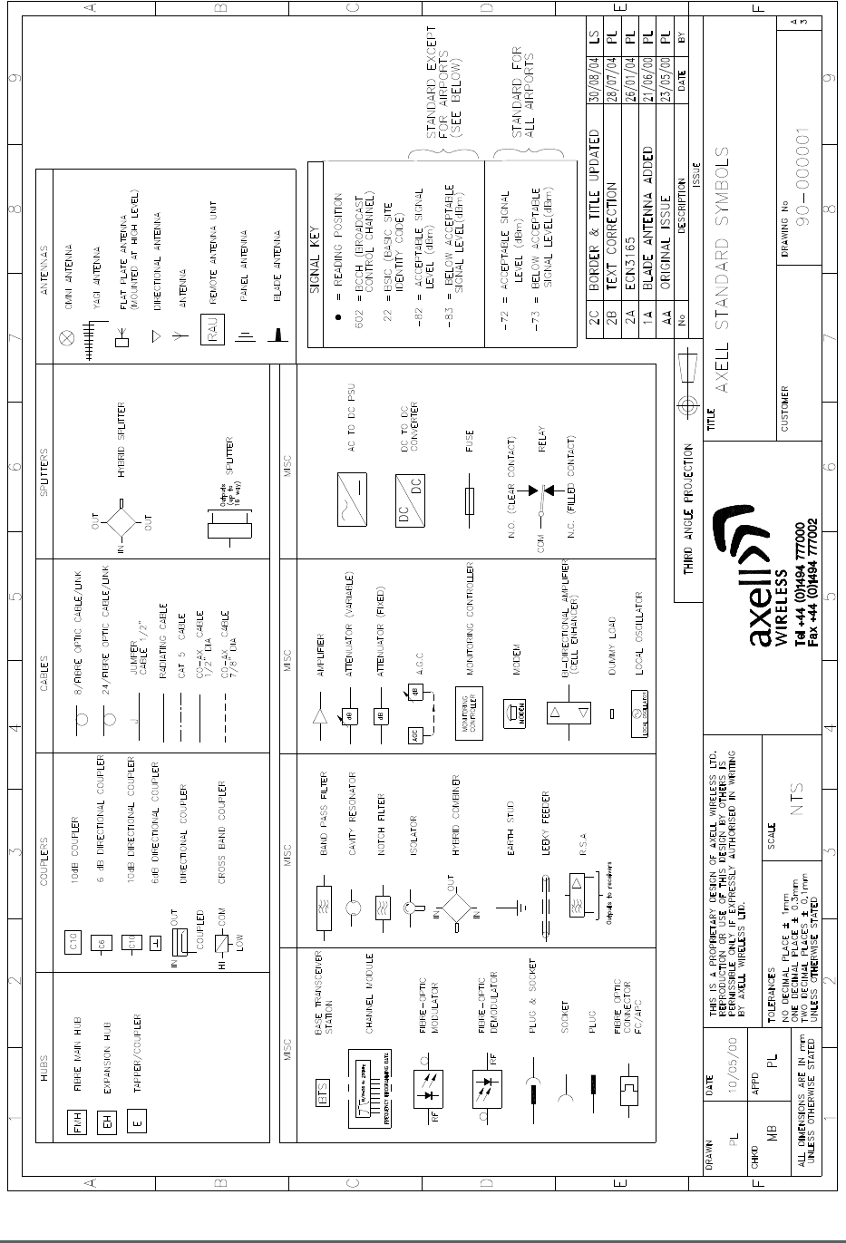
A.2. Key to Drawing Symbols used in this document

Axell Wireless Limited
Technical Literature
Fiber Optic, Uplink, Band Selective,
VHF Booster Amplifier
Document Number
60
-
274901HBK
Issue No. 2
Date 13/06/2011
Page
15
of
16
A.4. Waste Electrical and Electronic Equipment (WEEE) Notice
The Waste Electrical and Electronic Equipment (WEEE) Directive became law in
most EU countries during 2005. The directive applies to the disposal of waste
electrical and electronic equipment within the member states of the European
Union.
As part of the legislation, electrical and electronic equipment will feature the
crossed out wheeled bin symbol (see image at left) on the product or in the
documentation to show that these products must be disposed of in accordance
with the WEEE Directive.
In the European Union, this label indicates that this product should not be disposed of with domestic
or "ordinary" waste. It should be deposited at an appropriate facility to enable recovery and recycling.

Axell Wireless Limited
Technical Literature
Fiber Optic, Uplink, Band Selective,
VHF Booster Amplifier
Document Number
60
-
274901HBK
Issue No. 2
Date 13/06/2011
Page
16
of
16
A.5. Document Amendment Record
Issue
No.
Date Incorporated
by
Section
Amended
Reason for new issue
1 07/06/2011 AJS Draft
2 13/06/2011 AJS Issue