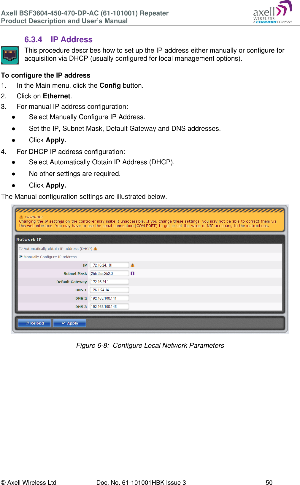
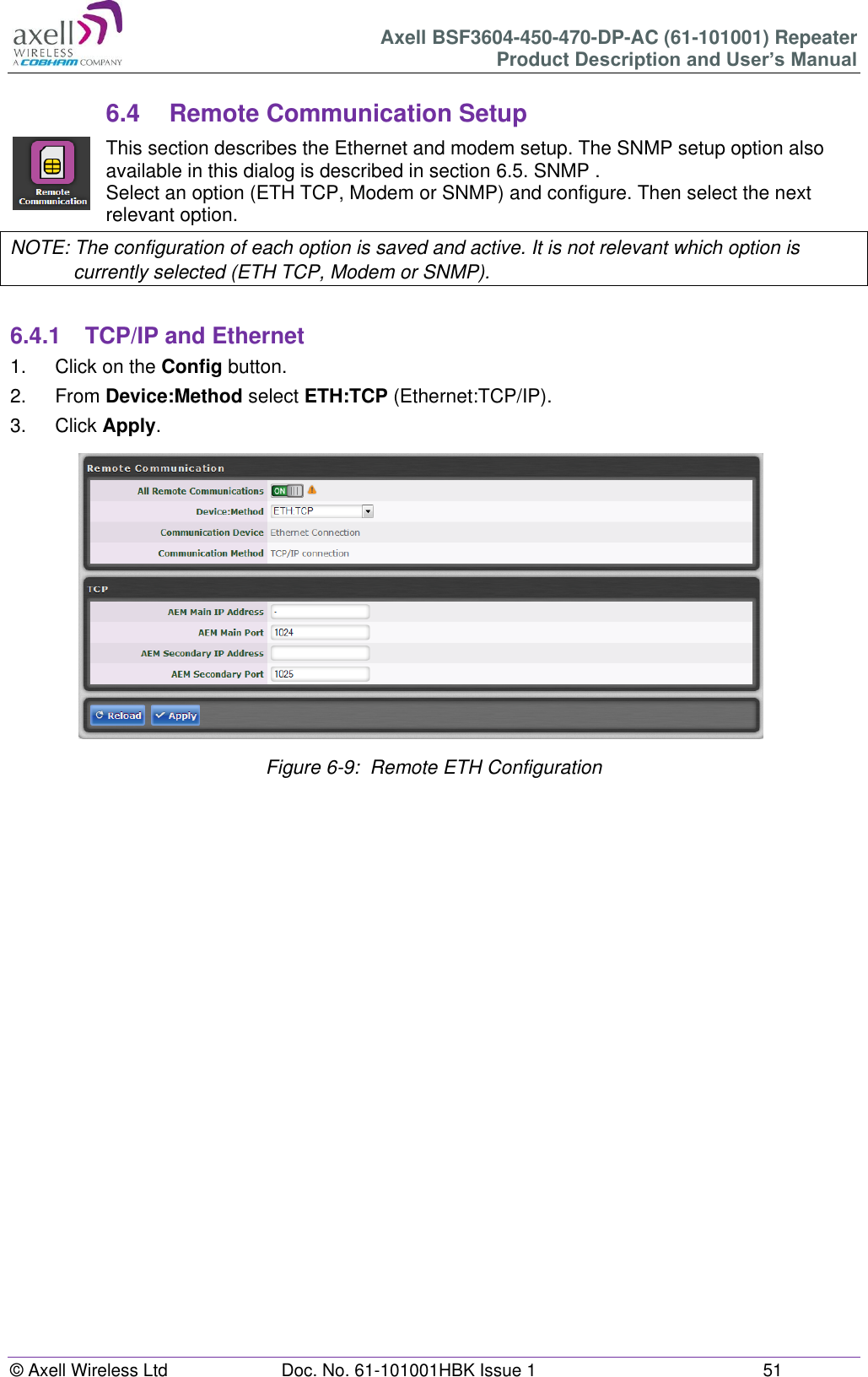
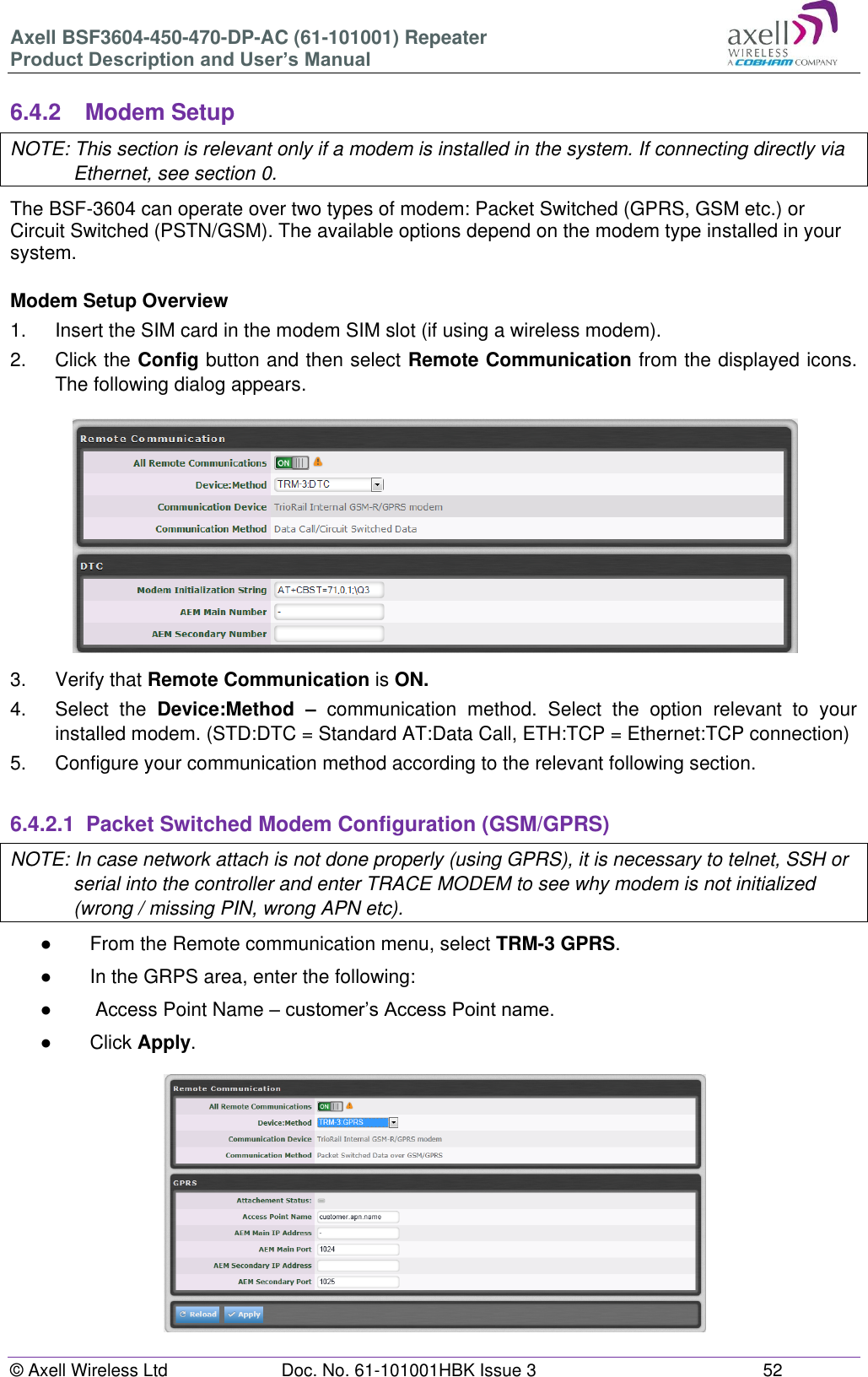
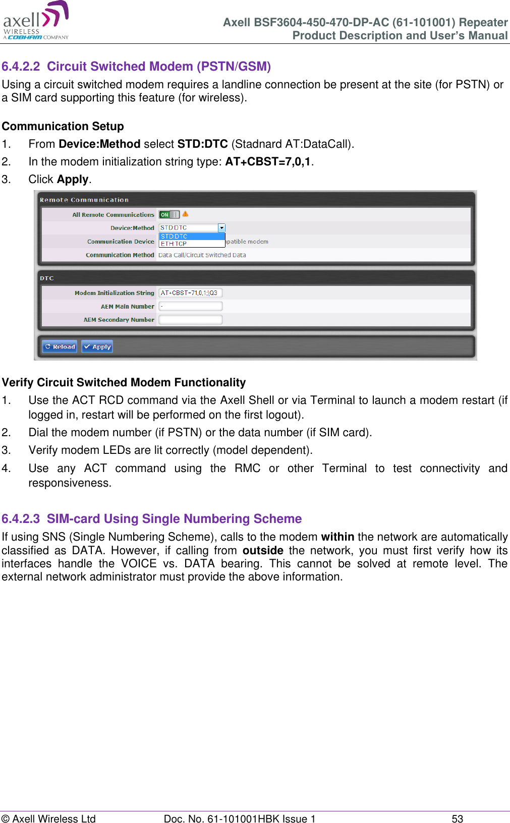
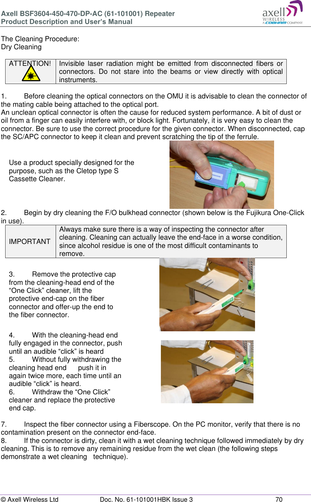
PBE Europe as Axell Wireless 61-101SERIES BSF3604-450-470-DP-AC UHF Band Selective Fibre Fed Booster User Manual BSF3604 450 470 DP AC UHF Fiber Optic Repeater

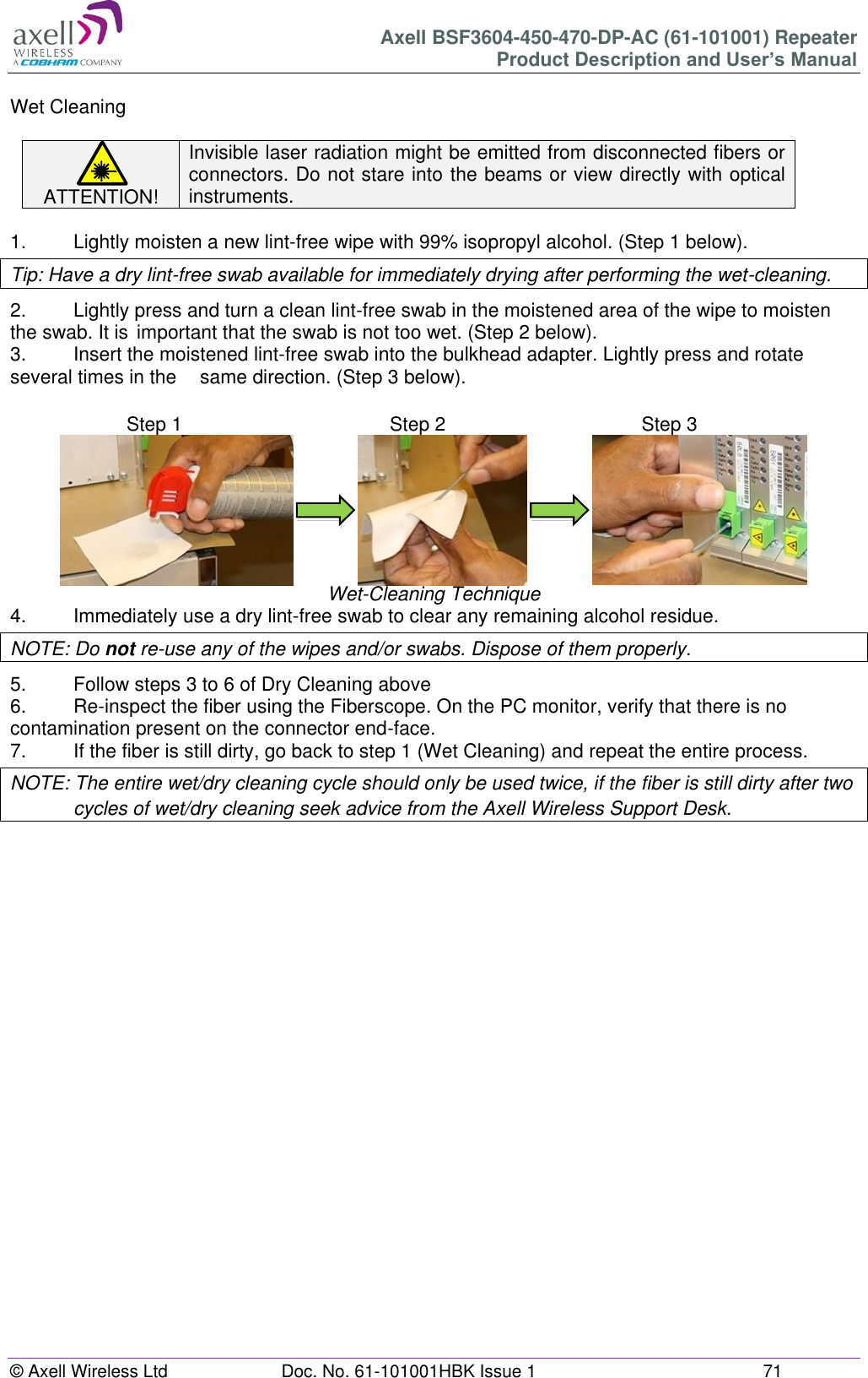
Axell Wireless BSF3604-450-470-DP-AC UHF Band Selective Fibre Fed Booster BSF3604 450 470 DP AC UHF Fiber Optic Repeater

User Manual

               BSF3604-450-470-DP-AC UHF Fiber Optic Repeater Part Number: 61-101001 Product Description and User’s Manual Document No. 61-101001HBK  This document is valid for the  BSF3604-450-470-DP-AC (450/470MHz) Repeaters for the US Market
Axell BSF3604-450-470-DP-AC (61-101001) Repeater Product Description and User’s Manual © Axell Wireless Ltd  Doc. No. 61-101001HBK Issue 3  2   Table of Contents 1 Notices .................................................................................................................................. 4 1.1 Copyright © 2015 Axell Wireless Ltd .................................................................................. 4 1.2 Contact Information ............................................................................................................ 4 1.3 About This Manual .............................................................................................................. 5 1.4 Compliance with FCC ......................................................................................................... 6 1.4.1 FCC Part 15 ............................................................................................................. 6 1.4.2 Unauthorized Changes to Equipment ...................................................................... 6 1.4.3 FCC RF Exposure Limits ......................................................................................... 6 1.4.4 Antenna Installation ................................................................................................. 7 1.4.5 Compliance with FCC deployment rule regarding the radiation of noise ................. 7 1.4.6 General Safety Warnings Concerning Use of This System ..................................... 9 2 Introduction ........................................................................................................................ 11 2.1 Features and Capabilities ................................................................................................. 12 2.2 Automatic Level Control ................................................................................................... 13 2.3 Operating Temperature .................................................................................................... 13 2.4 Management WEB GUI .................................................................................................... 14 2.5 Interfaces .......................................................................................................................... 14 2.5.1 Securing the Unit ................................................................................................... 14 2.5.2 External Interfaces ................................................................................................. 15 2.5.3 Internal Interfaces .................................................................................................. 16 3 Antenna and Repeater Installation Requirements .......................................................... 17 3.1 BSF-3604 Installation Requirements ................................................................................ 17 3.1.1 Safety Guidelines ................................................................................................... 17 3.1.2 Criteria for Repeater Installation Location ............................................................. 17 3.1.3 RF Cable Installation Guidelines ........................................................................... 18 3.1.4 F/O Cable Installation Guidelines .......................................................................... 18 3.2 Service Antenna Requirements ........................................................................................ 18 3.2.1 Required Antenna Information ............................................................................... 18 3.2.2 Indoor Installations ................................................................................................. 19 3.2.2.1 Recommended Antennas ................................................................................... 19 3.2.2.2 Recommended Splitters and Couplers .............................................................. 19 3.2.2.3 Installation Criteria ............................................................................................. 20 3.2.3 Service (Mobile) Antenna Installation Criteria ........................................................ 20 3.3 RF Cabling Requirements ................................................................................................ 20 4 Installation .......................................................................................................................... 21 4.1 Unpacking ......................................................................................................................... 21 4.2 Mount the Repeater .......................................................................................................... 21 4.2.1 Selecting a Location to Ensure Proper Cooling ..................................................... 22 4.2.2 Wall-Mounting Preparation .................................................................................... 22 4.2.3 Mount the Repeater on the Wall ............................................................................ 24 4.3 Grounding ......................................................................................................................... 26 4.4 Ensure Good Electromagnetic Vulnerability (EMV) Protection ......................................... 27 4.5 Fiber Optic Connection ..................................................................................................... 29 4.6 External Alarm and Relay Connections ............................................................................ 31 4.6.1 External Alarm ....................................................................................................... 31 4.6.2 Relay ...................................................................................................................... 31 4.7 Power and Backup Battery ............................................................................................... 32 4.7.1 Circuit Breaker ....................................................................................................... 32 4.7.2 Power Connections ................................................................................................ 32 4.7.2.1 Backup Battery ................................................................................................... 33 4.7.2.2 Connecting the Power Source ........................................................................... 33 4.7.3 Power ON .............................................................................................................. 34 4.7.3.1 Switching Power ON .......................................................................................... 34
Axell BSF3604-450-470-DP-AC (61-101001) Repeater Product Description and User’s Manual © Axell Wireless Ltd  Doc. No. 61-101001HBK Issue 1  3  4.7.3.2 Verifying LEDs ................................................................................................... 34 4.8 Closing and Securing the Repeater .................................................................................. 34 5 BSF-3604 Commissioning................................................................................................. 35 5.1 Open a Session to the BSF-3604 via the OMU II ............................................................. 35 5.2 BSF-3604 Optical Loss Adjustment (OLA) ....................................................................... 36 5.3 RF Balancing .................................................................................................................... 38 5.3.1 Manual RF Balancing ............................................................................................ 38 5.3.2 Automatic BSF-3604 RF Balancing ....................................................................... 40 5.4 Integration into the Axell Element Manager (AEM) .......................................................... 41 5.5 What Next? ....................................................................................................................... 41 6 BSF-3604 Full GUI Description ......................................................................................... 42 6.1 Opening a Direct Web Session ........................................................................................ 42 6.1.1 Connecting Locally ................................................................................................ 42 6.1.2 Remote Connection and Login .............................................................................. 43 6.2 Navigating the Web Interface ........................................................................................... 44 6.2.1 Management Options Buttons ............................................................................... 45 6.2.2 Home Screen Overview ......................................................................................... 46 6.2.3 Configuration Screen Overview ............................................................................. 47 6.3 Configuring General Parameters ...................................................................................... 48 6.3.1 Site Information – BSF-3604 Identification ............................................................ 48 6.3.2 Date & Time ........................................................................................................... 49 6.3.3 Configure External Alarms ..................................................................................... 49 6.3.4 IP Address ............................................................................................................. 50 6.4 Remote Communication Setup ......................................................................................... 51 6.4.1 TCP/IP and Ethernet .............................................................................................. 51 6.4.2 Modem Setup ........................................................................................................ 52 6.4.2.1 Packet Switched Modem Configuration (GSM/GPRS) ...................................... 52 6.4.2.2 Circuit Switched Modem (PSTN/GSM) .............................................................. 53 6.4.2.3 SIM-card Using Single Numbering Scheme ....................................................... 53 6.5 SNMP Support .................................................................................................................. 54 6.5.1 SNMP Traps Parameters ....................................................................................... 54 6.5.2 Activating and Configuring the SNMP Agent ......................................................... 54 6.6 User Accounts .................................................................................................................. 55 6.6.1 Default User Accounts ........................................................................................... 55 6.6.2 User Access Levels ............................................................................................... 56 6.6.3 Change Password ................................................................................................. 56 6.7 Reboot .............................................................................................................................. 57 6.8 Axell Shell (Command Line Interface) .............................................................................. 57 6.9 Attribute Reference ........................................................................................................... 58 7 Monitoring, Fault Sourcing and Maintenance ................................................................. 59 7.1 Cautions and General Statements ................................................................................... 59 7.2 Monitoring Via the BSF-3604 Home Screen .................................................................... 60 7.2.1 General Page Area ................................................................................................ 61 7.2.2 Detailed view of the BSF-3604 RF Status ............................................................. 61 7.2.3 Detailed view of Fiber Optic Unit ........................................................................... 62 7.2.4 Subsystems ........................................................................................................... 62 7.3 Logs Screen ..................................................................................................................... 63 7.4 Module LEDs .................................................................................................................... 64 7.4.1 Control Module LEDs ............................................................................................. 65 7.4.2 F/O Converter LEDs .............................................................................................. 66 7.4.3 Power Supply LEDs ............................................................................................... 67 Appendix A - Specification .......................................................................................................... 68 Appendix B - F/O Cleaning Procedure ........................................................................................ 69
Axell BSF3604-450-470-DP-AC (61-101001) Repeater Product Description and User’s Manual © Axell Wireless Ltd  Doc. No. 61-101001HBK Issue 3  4   1  Notices 1.1  Copyright © 2015 Axell Wireless Ltd All rights reserved. No part of this document may be copied, distributed, transmitted, transcribed, stored in a retrieval system, or translated into any human or computer language without the prior written permission of Axell Wireless Ltd. The manufacturer has made every effort to ensure that the instructions contained in this document are adequate and free of errors and omissions. The manufacturer will, if necessary, explain issues which  may  not  be  covered  by  this  document.  The  manufacturer's  liability  for  any  errors  in  the document is limited to the correction of errors and the aforementioned advisory services. This document has been prepared to be used by professional and properly trained personnel, and the customer assumes full responsibility when using them. The manufacturer welcomes customer comments as part of the process of continual development and improvement of the documentation in the best way possible from the user's viewpoint. Please submit your comments to the nearest Axell Wireless sales representative.  1.2  Contact Information  Headquarters Axell Wireless Aerial House  Asheridge Road  Chesham  Buckinghamshire HP5 2QD  United Kingdom   Tel: +44 1494 777000  Fax: +44 1494 777002   Commercial inquiries info@axellwireless.com Web site www.axellwireless.com Support issues support@axellwireless.com Technical Support Line,  English speaking +44 1494 777 747  Contact information for Axell Wireless offices in other countries can be found on our web site, www.axellwireless.com
Axell BSF3604-450-470-DP-AC (61-101001) Repeater Product Description and User’s Manual © Axell Wireless Ltd  Doc. No. 61-101001HBK Issue 1  5   1.3  About This Manual This Product Manual provides the following information: ●  Description of the BSF3604-450-470-DP-AC repeater  (hereinafter referred to as BSF-3604) ●  Procedures for installation, setup, configuration and checking the proper operation of the unit  ●  Maintenance and troubleshooting procedures  Intended Audience This Product Manual is intended for experienced technicians and engineers. It is assumed that the customers  installing,  operating,  and  maintaining  Axell  Wireless  Repeaters  are  familiar  with  the basic functionality of Repeaters. Notice Confidential - Authorized Customer Use This document may be used in its complete form only and is solely for the use of Axell Wireless employees  and  authorized  Axell  Wireless  channels  or  customers.  The  material  herein  is proprietary to Axell Wireless. Any unauthorized reproduction, use or disclosure of any part thereof is strictly prohibited. All trademarks and registered trademarks are the property of their respective owners. Disclaimer of Liability Contents  herein  are  current  as  of  the  date  of  publication.  Axell  Wireless  reserves  the  right  to change  the  contents  without  prior  notice.  The  information  furnished  by  Axell  Wireless  in  this document  is  believed  to  be  accurate  and  reliable.  However,  Axell  Wireless  assumes  no responsibility for its use. In no event shall Axell Wireless be liable for any damage resulting from loss of data, loss of use, or loss of profits and Axell Wireless further disclaims any and all liability for indirect, incidental, special, consequential or other similar damages. This disclaimer of liability applies to all products, publications and services during and after the warranty period.  Safety to Personnel ●  Before installing or replacing any of the equipment, the entire manual should be read and understood.  ●  This equipment is to be installed only in a restricted access location where access is restricted to is restricted to SERVICE PERSONNEL and to USERS who have been instructed on the restrictions and the required precautions to be taken. ● Throughout this manual, there are "Caution" warnings. "Caution" calls attention to a procedure or practice, which, if ignored, may result in injury or damage to the system, system component or even the user. Do not perform any procedure preceded by a "Caution" until the described conditions are fully understood and met.   This  notice  calls  attention  to  a  procedure  or  practice  that,  if  ignored,  may result in personal injury or in damage to the system or system component. Do not  perform  any  procedure  preceded  by  a  "CAUTION!"  until  described conditions are fully understood and met.
Axell BSF3604-450-470-DP-AC (61-101001) Repeater Product Description and User’s Manual © Axell Wireless Ltd  Doc. No. 61-101001HBK Issue 3  6   1.4  Compliance with FCC  Part 90 Signal Boosters             THIS IS A 90.219 CLASS B DEVICE    WARNING: This is NOT a CONSUMER device. This device is designed for installation by FCC LICENCEES and QUALIFIED INSTALLERS. You MUST have an FCC LICENCE or express consent of an FCC Licensee to operate this device.  You MUST register Class B signal boosters (as defined in 47 CFR 90.219) online at www.fcc.gov/signal-boosters/registration.  Unauthorized use may result in significant forfeiture penalties, including penalties in excess of $100,000 for each continuing violation.      The installation procedure must result in the signal booster complying with FCC requirements 90.219(d). In order to meet FCC requirements 90.219 (d), it may be necessary for the installer to reduce the UL and/or DL output power for certain installations.    1.4.1  FCC Part 15 This  device  complies  with  part  15  of  the  FCC  Rules.  Operation  is  subject  to  the  following  two conditions:   1.  This device may not cause harmful interference, and   2.  This device must accept any interference received, including interference that may cause undesired operation.   If not installed and used in accordance with the instructions, this equipment generates, uses and can radiate radio frequency energy. However, there is no guarantee that interference will not occur in a particular installation. If this equipment does cause harmful interference to RF reception, which can be determined by turning the equipment off and on, the user is encouraged to try to correct the interference by one or more of the following measures:  ●  Reorient or relocate the Donor antenna. ●  Increase the separation between the equipment and receiver. ●  Connect the equipment into a power outlet on a circuit different from that to which the receiver is connected.  1.4.2  Unauthorized Changes to Equipment Changes or Modifications not expressly approved by the manufacturer responsible for compliance could void the user’s authority to operate the equipment  1.4.3  FCC RF Exposure Limits This unit complies with FCC RF exposure limits for an uncontrolled environment. This equipment can only be installed for applications, driving passive or active DAS systems. All antennas must be operated at a minimum distance of 47 cm between the radiator and any person’s body.
Axell BSF3604-450-470-DP-AC (61-101001) Repeater Product Description and User’s Manual © Axell Wireless Ltd  Doc. No. 61-101001HBK Issue 1  7   1.4.4  Antenna Installation Installation of an antenna must comply with the FCC RF exposure requirements. The antenna used for this transmitter must be mounted on permanent structures.    The FCC regulations mandate that the ERP of type B signal boosters should not exceed 5W, this is equivalent to 8.2W EIRP.  Therefore the max antenna gain allowed for this type of signal booster should be limited to the values given by equation 1 (below) for the service antenna.   Equation (1) - Max SERVICE antenna gain Max SERVICE antenna gain (dBi) = 39.1 – (37dBm - # of antennas in dB – cable losses in dB).  For example: No. of Antennas Cable Losses Max Allowed Antenna Gain 4 3 39.1 - (37-6-3) =11.1dBi 1 3 39.1- (37-0-3) = 5.1dbi 10 3 39.1- (37-10-3) = 15.1dbi   1.4.5  Compliance with FCC deployment rule regarding the radiation of noise  Good engineering practice must be used in regard to the signal booster’s noise radiation. Thus, the gain of the signal booster should be set so that the ERP of the output noise from the signal booster should not exceed the level of -43 dBm in 10 kHz measurement bandwidth.  In the event that the noise level measured exceeds the aforementioned value, the signal booster gain should be decreased accordingly.  In general, the ERP of noise on a spectrum more than 1 MHz outside of the pass band should not exceed -70 dBm in a 10 kHz measurement bandwidth.  The BSF-3604 61-101001 Repeater has a noise  level of  -59 dBm in 10 kHz measurement at  1 MHz spectrum outside the passband of the signal booster and an in-band noise level at around -40 dBm in a 10 kHz bandwidth. Therefore, the noise at the antenna input port should be calculated based on equation (3).   Equation (2) - Input Noise to service antenna Input Noise to service antenna: -59 dBm – Antenna splitter losses in dB – cable loss in dB
Axell BSF3604-450-470-DP-AC (61-101001) Repeater Product Description and User’s Manual © Axell Wireless Ltd  Doc. No. 61-101001HBK Issue 3  8   Example: In band Noise Signal booster connected to 10 service antennas with a 100m long ½ inch cable. Losses of such a cable with the connectors = ~ 12dB  Assuming 10 service antennas: antenna splitter losses = 11 dB  Based on equation (3) Input antenna noise (to the antenna) = -40-12 -11=-63 dBm ERP The in-band input noise to the antenna should be -40 -12-11= -63dbm ERP   Example: Out of band noise Signal booster connected to 10 service antennas with a 100m long ½ inch cable. Losses of such a cable with the connectors = ~ 12dB  Assuming 10 service antennas: antenna splitter losses = 11 dB  Based on equation (3) Input antenna noise (to the antenna) = -59 -12 -11=--82dBm ERP The Out of-band input noise to the antenna should be -59 -12-11= -82dbm ERP   NOTE: In this example there is no need to add an external band pass filter to attenuate the out of band noise. If fewer antennas are deployed then additional filtering may be required Conclusion:   Good engineering practice requires that  in general when the out of band noise measured at the service antenna input is more than -70 dBm per 10 kHz measurement bandwidth, an external band pass  filter should be added to attenuate the out of band noise level.  All  Axell  Wireless  repeaters  include  high  selectivity  duplexers  and  filters  to  attenuate  the  out  of band noise. Should additional filtering be required, we have a comprehensive range of interference filters which can be supplied upon request.
Axell BSF3604-450-470-DP-AC (61-101001) Repeater Product Description and User’s Manual © Axell Wireless Ltd  Doc. No. 61-101001HBK Issue 1  9   1.4.6  General Safety Warnings Concerning Use of This System Always observe standard safety precautions during installation, operation and maintenance of this product. Caution labels! Throughout  this  manual,  there  are  "Caution"  warnings.  "Caution"  calls attention to a procedure or practice, which, if ignored, may result in injury or damage to the system, system component or even the user. Do not perform  any  procedure  preceded  by  a  "Caution"  until  the  described conditions are fully understood and met.  Danger: Electrical Shock To  prevent  electrical  shock  when  installing  or  modifying  the  system power wiring, disconnect the wiring at the power source before working with un insulated wires or terminals. Caution: Safety to personnel Before  installing  or  replacing  any  of  the  equipment,  the  entire  manual should be read and understood.  The  user  needs  to  supply  the  appropriate  AC  power  to  the  repeater. Incorrect power settings can damage the repeater and may cause injury to the user.  Please  be  aware  that  the  equipment  may,  during  certain  conditions become very warm and can cause minor injuries if handled without any protection, such as gloves. Caution: RF Exposure RF  radiation,  arising  from  transmitter  outputs  connected  to  AWL’s equipment, must be considered a safety hazard.  This condition might  only occur in the  event of cable disconnection,  or because  a  ‘spare’  output  has  been  left  un-terminated.  Either  of  these conditions would impair the system’s efficiency. No investigation should be carried out until all RF power sources have been removed. This would always be a wise precaution, despite the severe mismatch between the impedance  of  an  N  type  connector  at  50Ω,  and  that  of  free  space  at 377Ω,  which  would  severely  compromise  the  efficient  radiation  of  RF power. Radio frequency burns could also be a hazard, if any RF power carrying components were to be carelessly touched!  Antenna positions should be chosen to comply with requirements (both local & statutory) regarding exposure of personnel to RF radiation. When connected  to  an  antenna,  the  unit  is  capable  of  producing  RF  field strengths,  which  may  exceed  guideline  safe  values  especially  if  used with  antennas  having  appreciable  gain.  In  this  regard  the  use  of directional  antennas  with  backscreens  and  a  strict  site  rule  that personnel must remain behind the screen while the RF power is on, is strongly recommended.  Where  the  equipment  is  used  near  power  lines  or  in  association  with temporary masts not having lightning protection, the use of a safety earth connected to the case-earthing bolt is strongly advised.
Axell BSF3604-450-470-DP-AC (61-101001) Repeater Product Description and User’s Manual © Axell Wireless Ltd  Doc. No. 61-101001HBK Issue 3  10   Caution: Safety to equipment When  installing,  replacing  or  using  this  product,  observe  all  safety precautions  during  handling  and  operation.  Failure  to  comply  with  the following  general  safety  precautions  and  with  specific  precautions described  elsewhere  in this manual violates the safety  standards  of  the design, manufacture, and intended use of this product.   Changes or modifications not expressly approved by the party responsible for compliance could void the user’s authority to operate the equipment. Axell  Wireless  assumes  no  liability  for  the  customer's  failure  to  comply with  these  precautions.  This  entire  manual  should  be  read  and understood before operating or maintaining the repeater. Warning: Restricted Access Location This Axell Wireless equipment is to be installed only in a restricted access location  where  access  is  restricted  to  SERVICE  PERSONNEL  and  to USERS  who  have  been  instructed  on  the  restrictions  and  the  required precautions to be taken. Attention: Electrostatic Sensitivity Observe electrostatic precautionary procedures. ESD = Electrostatic Discharge Sensitive Device.  Static  electricity  can  be  conducted  to  the  semiconductor  chip  from  the center pin of the RF input connector, and through the AC connector pins. When  unpacking  and  otherwise  handling  the  repeater,  follow  ESD precautionary  procedures  including  use  of  grounded  wrist  straps, grounded workbench surfaces, and grounded floor mats. Caution: Class 1 Laser The repeaters described in this manual are equipped with class 1 lasers, as per definition in EN 60825-1 Caution! - Un-terminated optical receptacles may emit laser radiation. Exercise caution as follows: ●  Do not stare into the beam or view with optical instruments. Optical transmitters in the fiber optic converter can send out high energy invisible laser radiation. There is a risk for permanent damage to the eye. ●  Always use protective cover on all cables and connectors which are not connected.  ●  Never look directly into a fiber cable or a connector.  ●  Consider that a fiber can carry transmission in both directions.  ●  During handling of laser cables or connections, ensure that the source is switched off.  ●  Regard all open connectors with respect and direct them in a safe direction and never towards a reflecting surface. Reflected laser radiation should be regarded as equally hazardous as direct radiation.
Axell BSF3604-450-470-DP-AC (61-101001) Repeater Product Description and User’s Manual © Axell Wireless Ltd  Doc. No. 61-101001HBK Issue 1  11   2  Introduction  The BSF-3604 is a fiber optic fed UHF repeater. It is part of a system that is fed from an Axell Wireless Optical Master Unit Mk. 2 (OMU II), supporting WDM technology, lowering the number of fibers  needed  per  system.    The  maximum  optical  loss  of  up  to  10dB  is  allowed  over  the  fiber interconnecting  the  OMU II  and  the  most  distant  last  remote  unit  that  the  OMU  supports.  This offers great flexibility when providing RF coverage in areas where it is not possible to rely on off-air transmission.   The fiber optic system is easily remotely monitored and controlled by Axell Wireless’ effective supervision tool, The Axell Wireless Element Manager (AEM).  The BSF-3604 includes automatic optical gain settings, where the gain is adjusted in the downlink chain by measuring the level of the pilot carrier sent from the OMU II. The level of the received pilot carrier is continuously monitored.                 Figure 2-1 Illustration of OMU II Connection to BSF Remote
Axell BSF3604-450-470-DP-AC (61-101001) Repeater Product Description and User’s Manual © Axell Wireless Ltd  Doc. No. 61-101001HBK Issue 3  12   2.1  Features and Capabilities ●  Supports frequency bands  450-470MHz ●  Operational bandwidth:   0-5 MHz ●  Duplex Distance:     0-5 MHz ●  Output Power per carrier UL/DL:  ●  1 carrier:   + 36dBm ●  2 carriers:   + 33dBm ●  3-4 carriers:  +30dBm ●  8 carriers:   +27dBm ●  Supports WDM technology ●  Automatic Optical Gain Setting via OMU II ●  Remote configuration and management: ●  Via OMU II intuitive Web GUI ●  Via AEM – automatically detected via AEM no local setup required  ●  Optionally via Ethernet or  GSM, GSM-R PSTN modem ●  SNMP v1/v2c support ●  Automatic Level Control (ALC) -  provides constant gain in both uplink and downlink paths according to the  defined maximum output level ●  Very low noise factor - minimizes interference to BTS and increases high speed data throughput ●  Backup battery for ‘last gasp’, sending fault error before power failure ●  Wall or pole mount conforming to IP65 and NEMA 4 standard ●  Power source:  115VAC, 230 VAC or -48V power (depending on your order)
Axell BSF3604-450-470-DP-AC (61-101001) Repeater Product Description and User’s Manual © Axell Wireless Ltd  Doc. No. 61-101001HBK Issue 1  13   2.2  Automatic Level Control The  repeater  is  equipped  with  Automatic  Level  Control  (ALC).  The  ALC  feature  enables maintaining the maximum defined output level.  The  repeater  has  a  defined  maximum  output  level.  If  the  input  signal  amplified  by  the  gain  set exceeds the set output limit, an ALC loop is activated. This ALC ensures that the amplifier does not add distortion to the radio signal. Below are examples of the ALC function for one and two carriers.  2.3  Operating Temperature The BSF-3604 is designed primarily for multi carrier purposes. If the repeater is run at full output power  over  a  long  period  of  time,  the  convection  cooling  may  not  be  enough.  The  repeater  is equipped with a power management function that steps down the power and, if needed, fully shuts down the amplifier chains until temperature reaches normal values. In situations where a repeater will be run in such a manner extra cooling can be provided by putting the repeater in a temperature controlled environment or via external fans.     +20Input Signal, dBmOutput Power Level, dBmGain 70dB-50ALCALC one carrierInput signal, dBmOutput power, dBm+36,5+33,8-24 -16Gain: 60 dB+35ALC two carriers
Axell BSF3604-450-470-DP-AC (61-101001) Repeater Product Description and User’s Manual © Axell Wireless Ltd  Doc. No. 61-101001HBK Issue 3  14   2.4  Management WEB GUI BSF-3604 is remotely commissioned and monitored via an OMU II session. Local access to the unit is not required for commissioning.  Additional  configuration  and troubleshooting  options  are available via  a  direct  connection  to  the BSF-3604 IP address. A direct session can be opened locally or remotely. NOTE: Direct remote communication requires connecting the BSF-3604 to an Ethernet network and configuration of an IP address, or via GSM/GSM-R PSTN modem.  2.5  Interfaces The BSF-3604 unit provides the following interfaces: ●  Lockable door catches for protection and security ●  External TX and RX antenna and GND connections  ●  External connection for power ● Internal connection for fiber optics and alarm cables routed via cable gland on the side of the unit ● Internal USB/Ethernet connection for (optional) management and analysis via Web GUI routed via cable gland on the side of the unit  2.5.1  Securing the Unit The repeaters are secured with two, quarter-turn door catches which can be locked with a key.  NOTE: The two door catches must be fully closed and locked. Failure to do so will affect the IP65 compliancy and therefore any warranty.                           Figure 2-2: Securing the Unit
Axell BSF3604-450-470-DP-AC (61-101001) Repeater Product Description and User’s Manual © Axell Wireless Ltd  Doc. No. 61-101001HBK Issue 1  15   2.5.2  External Interfaces The repeater’s external interfaces are located on the right-hand side of the unit                                     Figure 2-3: ports and connections  The following table provides a description of the ports and connections.  Port Description D/L DAS RF Port Downlink output connection to TX Antenna – N type connector, female U/L DAS RF Port Uplink input connection from RX Antenna – N type connector, female Cable Gland The fiber optic cable link from the master site is routed through this gland. The optional Ethernet connection for management and analysis via Web GUI may also be routed through this gland.  Connections for routing external alarms and relay wiring cable for internal connections (section 4.6.) are also routed through this cable gland Power Connection AC inlet, 3 pole panel plug (section 4.7.) Grounding Connection Grounding bolt (section 4.3.)
Axell BSF3604-450-470-DP-AC (61-101001) Repeater Product Description and User’s Manual © Axell Wireless Ltd  Doc. No. 61-101001HBK Issue 3  16   2.5.3  Internal Interfaces This section shows the internal interfaces for the repeater. You will need to open the Repeater in order to do the following: ●  Connect optic fibers ●  Connect alarms (if relevant) ●  Power-on (Power-ON and Battery ON switches) ● USB/Ethernet port for local setup                                 Figure 2-4: Repeater with Door Open  Feature Description Rechargeable  Backup Battery provides the Control Module and modem with enough capacity to send an alarm in case of input power failure. See section 4.2.7.1. Power and battery Switches Separate switches for PSU module and Backup Battery. See section 4.7.3. Controller Module Provides RS232 ,USB and Ethernet ports for local and remote control and reporting/interrogation of alarm data. See section 7.4.1. Fiber Optic Converter module The fiber optic transceiver module. See section 7.4.2. Alarm and Relay Connections The external alarm interface card. See Section 4.6.
Axell BSF3604-450-470-DP-AC (61-101001) Repeater Product Description and User’s Manual © Axell Wireless Ltd  Doc. No. 61-101001HBK Issue 1  17   3  Antenna and Repeater Installation Requirements This chapter provides information on the Remote installation site requirements, on the installation requirements of the antennas, the specifications of the service antennas suitable for operation with this remote and RF and F/O cable requirements.  3.1  BSF-3604 Installation Requirements 3.1.1  Safety Guidelines Before installing the Repeater, review the following safety information:  ●  Follow all local safety regulations when installing the Repeater. ●  Only qualified personnel are authorized to install and maintain the Repeater. ●  Ground the Repeater with the grounding bolt located on the external lower side of the Repeater. ●  Do not use the grounding bolt to connect external devices. ●  Follow Electro-Static Discharge (ESD) precautions. ●  Use low loss cables to connect the antennas to the Repeater.  Class 1 Laser This product is equipped with class 1 lasers,  as per definition in EN 60825-1.       Un-terminated optical receptacles may emit laser radiation. Do not stare into the beam or view with optical instruments  3.1.2  Criteria for Repeater Installation Location The following criteria should be considered when selecting the Repeater installation site location: ●  Application type ●  General surroundings ●  Available installation ●  Install the Repeater in a shielded, ventilated, and easy-to-reach area. ● Verify that there is a minimum of a 50 cm (20”) radius of space around the Repeater, enabling easy access to the repeater for maintenance and on-site inspection. ●  Distance from antenna site - It is recommended that the installation location be as close as possible to the antenna site in order to maintain the cable loss to a minimum. ●  The Repeater is convection cooled so airflow and alternation should be possible. ●  Follow Electro-Static Discharge (ESD) precautions. ●  Install the Repeater close to the service area to monitor the output power. ●  Use low loss cables to connect the antennas to the Repeater.
Axell BSF3604-450-470-DP-AC (61-101001) Repeater Product Description and User’s Manual © Axell Wireless Ltd  Doc. No. 61-101001HBK Issue 3  18   3.1.3  RF Cable Installation Guidelines Required: ●  For all coaxial connections to/from the Repeater - high performance, flexible, low loss 50Ω coaxial communications cable.  ●  All cables shall be weather-resistant type.  ●  Cable length - determined by the Repeater installation plan. When calculating the cable length, take into account excess cable slack so as not to limit the insertion paths.  3.1.4  F/O Cable Installation Guidelines Use the following over the complete link between the Remote and OMU: ●  Use SC/APC connectors (8 degree angle) for all connections ●  Cable length - determined by the Remote installation plan. When calculating the cable length, take into account excess cable slack so as not to limit the insertion paths.  Recommended fiber-optic cable:  ●  Single-mode type fiber 9/125  3.2  Service Antenna Requirements   a. The installer is held accountable for implementing the rules required for deployment. b. Good engineering practice must be used to avoid interference. c. Output power should be reduced to solve any IMD interference issues.  The  Service  antenna  type  (i.e.  the  antenna  feeding  the  mobile/remote  units)  depends  on  the design of the DAS.   3.2.1  Required Antenna Information The following antenna requirements, specifications and site considerations should be met: ●  Type of  installation – DAS/Radiating Cable ●  Service area type and size  ●  Antenna type and characteristics ●  Height ● Length and type of coaxial cable required for connecting the antenna to the Repeater and the attenuation.
Axell BSF3604-450-470-DP-AC (61-101001) Repeater Product Description and User’s Manual © Axell Wireless Ltd  Doc. No. 61-101001HBK Issue 1  19   3.2.2  Indoor Installations  3.2.2.1  Recommended Antennas The  following  describes  the  requirements  for  an  omnidirectional  mobile  used  for  indoor applications. Specifications: ●  One or a combination of the following antennas can be used: Ceiling Mount Patch antenna, Wall Mount Patch antenna, Corner Reflector. ●  Choose an antenna with high side lobe attenuation which enables maximum isolation from other co-located antennas. ●   Equation (1) - Max SERVICE antenna gain Max SERVICE antenna gain (dBi) = 39.1 – (37dBm - # of antennas in dB – cable losses in dB).  For example: No. of Antennas Cable Losses Max Allowed Antenna Gain 4 3 39.1 - (37-6-3) = 11.1dBi 1 3 39.1- (37-0-3) = 5.1dBi 10 3 39.1- (37-10-3) = 15.1dBi  Typical Antenna Types: ● Indoor Dome 2.1dBi beam width 360o ● Indoor Panel 4.2dBi beam width 106o ●  Radiating Cable Typically < -50dBi   3.2.2.2  Recommended Splitters and Couplers  Axell Wireless can supply a comprehensive range of splitters and Couplers to aid the installation of the DAS system. Typical specifications as below:  Splitter Part Numbers 90-851202 90-851203 90-851204 Frequency Band 300 - 500MHz Split 2 way 3 way 4 way Max Insertion Loss 0.3dB 0.5dB 0.4dB Split Loss 3dB 4.8dB 6dB  Coupler Part Number 90-852306 90-852310 90-852315 90-852320 Frequency Band  300 - 500MHz Coupling -6dB ±1.0dB -10dB ±1.0dB -15dB ±1.0dB -20dB ±1.0dB Max Mainline Loss 1.7dB 0.8dB 0.4dB 0.22dB
Axell BSF3604-450-470-DP-AC (61-101001) Repeater Product Description and User’s Manual © Axell Wireless Ltd  Doc. No. 61-101001HBK Issue 3  20   3.2.2.3  Installation Criteria Determine the antenna installation configuration, according to the transmission requirements and the installation site conditions. Installation requirements: ●  An indoor antenna should be installed at a convenient location. It should be free of metallic obstruction. Install the Service Antenna at the designated height and tune it roughly toward the Service coverage area. 3.2.3  Service (Mobile) Antenna Installation Criteria Determine the antenna installation configuration, according to the transmission requirements and the installation site conditions. Installation requirements: ●  An indoor antenna should be installed at a convenient location. It should be free of metallic obstruction. ●  Install the Service Antenna at the designated height and tune it roughly toward the Service coverage area. ●  Installation of this antenna must provide a minimum separation distance of 47 cm from any personnel within the area.  3.3  RF Cabling Requirements ●  For all coaxial connections to/from the Repeater - high performance, flexible, low loss 50Ω coaxial communications cable.  ●  All cables shall be weather-resistant type.  ●  Cable length - determined by the Repeater installation plan. When calculating the cable length, take into account excess cable slack so as not to limit the insertion paths. ●  Make sure that cable and connector are compatible. Using cables and connectors from the same manufacturer is helpful. ●  All connectors must be clean and dry ●  Waterproof all outdoor connections using silicone, vulcanizable tape or other suitable substance as moisture and dust can impair RF characteristics.  ●  Make sure enough room has been allocated for the bending radius of the cable. RF cables must not be kinked, cut or damaged in any way ●  Connect the RF cable to the antenna tightly but without damaging threads ●  Fasten cables tight to cable ladder or aluminum sheet ● For short length of feeder cables use ½ “, for longer feeder cables use 7/8”. Chose thicker coax cables for lower attenuation. Minimize the length of the coax cables to reduce the attenuation  ●  Use jumper cable for easy installation. The RF Coaxial cable can be substituted at each end with a jumper cable.
Axell BSF3604-450-470-DP-AC (61-101001) Repeater Product Description and User’s Manual © Axell Wireless Ltd  Doc. No. 61-101001HBK Issue 1  21   4  Installation 4.1  Unpacking Inspect the shipped material before unpacking the equipment, document any visual damage and report according to routines. A delivery of a repeater from Axell Wireless contains: ● Checklist with delivered items ●  Repeater with attached wall mounting brackets ●  Mains lead ●  Keys to repeater  ●  Rubber inset for fiber inlet cable gland ● CD containing User’s Manual and RMC ●  Any other specifically ordered item  4.2  Mount the Repeater The BSF-3604 Remote is designed to be mounted on a wall. The Repeater is delivered with wall mounting brackets attached.   Mount  the  repeater  in  an  accessible  location  and  in  a  location  that  fulfils  the  environmental requirements. Mounting must be tight to eliminate vibration.
Axell BSF3604-450-470-DP-AC (61-101001) Repeater Product Description and User’s Manual © Axell Wireless Ltd  Doc. No. 61-101001HBK Issue 3  22   4.2.1  Selecting a Location to Ensure Proper Cooling ●  Mount the repeater so that heat can be dispersed from it.  ● The repeater wall mounting brackets ensure an optimum airflow between the wall and the heat-sink on the rear of the repeater.  ●  Do not block this air channel as it will cause the MTBF of the repeater to drop dramatically, or even in the worst case cause the repeater to fail completely.  ●  If possible, use a wall in the shade to minimize the overall sun loading. If sufficient shielding cannot be obtained, an additional sun shield should be mounted.    Figure 4-1: Example of a sun shield  4.2.2  Wall-Mounting Preparation  It is recommended that two people lift the repeater since (depending upon the configuration) the BSF-3604 weighs approximately 30 kg.  ● Wall compatibility - check the suitability of the wall on which the BSF-3604 is to be to be fitted.  ● Plan mount - check the actual fixing centers (see below) and overall dimensions of the BSF-3604 enclosure.  The BSF-3604 is fitted with wall mounting brackets which provide adequate ventilation between the BSF-3604 and the wall to which it is fixed. ● Plan connection cable clearances - the Optical, RF and power connections located on the side of the BSF-3604 will need at least 300mm clearance to enable the connections to be made. The minimum bend radius for Optical and RF cables must not be less than the recommendations made by the cable manufacturer. Plan the cable runs and ensure adequate space is available. ● Allow for door opening - ensure that there is sufficient space at the front of the BSF-3604 to allow the door to be fully opened and for maintenance engineers to get access to the unit with test equipment such as a spectrum analyzer. Allow an additional 500mm of space in front of the BSF-3604 when the door is fully open. ● Fix bolts –fix M8 Rawbolts or similar (100mm in length) into the wall at the dimensions as illustrated in figure 1 below using equipment as specified by the fixing manufacturer. A recommended method is set out below. Care must be taken to ensure the alignment of the four fixings. A spirit level or plumb line should be used to ensure horizontal/vertical alignment.
Axell BSF3604-450-470-DP-AC (61-101001) Repeater Product Description and User’s Manual © Axell Wireless Ltd  Doc. No. 61-101001HBK Issue 1  23  468.2mm559.3mm234.1mm 234.1mmHole to takeM8 RawlboltHole to takeM8 RawlboltHole to takeM8 RawlboltHole to takeM8 RawlboltCenter line of BSF100mm8mm dia.Bolt headWasherSleeve/Anchor BSF-3604 should be fixed to a solid wall (these include brickwork, blockwork, and concrete.), due to the weight of the cell enhancer, fixing to a hollow wall is not recommended. Always check that there are no pipes or cables hidden in the wall beneath the area to be drilled. Various pipe and cable detectors are available to check this.  To  provide  secure  fixing  to  a  solid  wall,  the most common method is drilling and plugging. The size of fixing is dependent on the item to be  fixed  and  the  nature  of  the  wall,  Repeater 50-122503 should be fixed with mild steel, M8 x 100mm rawl bolts or similar.  Right: M8 rawl bolt of the type recommended to fix BSF-3604 to a wall.   First mark out on the chosen wall the fixing centers of the BSF                                    Figure 4-2: Fixing Centers
Axell BSF3604-450-470-DP-AC (61-101001) Repeater Product Description and User’s Manual © Axell Wireless Ltd  Doc. No. 61-101001HBK Issue 3  24  100mm8mm dia.Bolt headWasherSleeve/Anchor 4.2.3  Mount the Repeater on the Wall The Repeater wall mount brackets assembly should be fixed to a solid wall (these include brickwork, blockwork, and concrete.);  (Due to the weight of the Repeater, it is NOT recommended to fix to a hollow wall).       Figure 4-3: M8 Rawlbolt – recommended for wallmount.  Always check that there are no pipes or cables hidden in the wall beneath the area to be drilled. Various pipe and cable detectors are available for this type of inspection. To provide secure fixing to a solid wall, the most common method is drilling and plugging. The size of fixing is dependent on the item to be fixed and the nature of the wall, The Repeater should be fixed with mild steel, M8 (100mm) rawlbolts or similar.  1.  Mark out the fixing centers of the repeater on the chosen wall (see 4.2.2).  2.  Mark  and  drill  the  wall  with  the  correct  size  masonry  bit  as  specified  by  the  fixing manufacturer. NOTE: It is good practice to wear goggles to protect your eyes from flying debris when using power tools. 3.  Hold the drill bit  against the mark and begin drilling slowly so that the bit does not wander from the position. The wall should be drilled to a depth which is sufficient to accommodate the full length of the fixing.  4.  Insert the fixings so that the top of the sleeve/anchor section is level with the wall   surface. Gently tighten the bolt by hand so that the anchor section of the fixing expands and grips the inside of the hole.                       Figure 4-4: Inserting Fixing and Tightening.
Axell BSF3604-450-470-DP-AC (61-101001) Repeater Product Description and User’s Manual © Axell Wireless Ltd  Doc. No. 61-101001HBK Issue 1  25   5.  As the bolt pulls its way in, the sides of the anchor section are forced outwards, gripping the surrounding surface.  Figure 4-5: Anchor Sides Pushed Outwards. 6.  Once all four fixings are in place, carefully withdraw the four bolts.   Figure 4-6: Withdraw Bolts. 7.  Align repeater with the four fixings. Great care should be exercised here as the repeater is very heavy. Once repeater is held in the chosen position (a suitably rated heavy duty scissor lift table/trolley may be suitable for this operation). Carefully insert the fixing bolts through the mounting lugs of the Repeater and into the sleeve/anchor sections of the fixing in the wall and tighten the bolts.   Figure 4-7: Mount Repeater     Align Repeater and Secure Bolts
Axell BSF3604-450-470-DP-AC (61-101001) Repeater Product Description and User’s Manual © Axell Wireless Ltd  Doc. No. 61-101001HBK Issue 3  26   4.3  Grounding  This equipment must be grounded. Connect the grounding protection as follows:  ●  Ensure that good grounding protection measures are taken to create a reliable repeater site.  ●  Make sure to use adequately dimensioned grounding cables. The minimum recommended conductive area for a grounding cable is 16mm2 ●  Make sure the grounding product used is suitable for the kind and size of cable being used.  ●  Connect the repeater grounding bolt to the same ground.                            Figure 4-8: Grounding the BSF-3604
Axell BSF3604-450-470-DP-AC (61-101001) Repeater Product Description and User’s Manual © Axell Wireless Ltd  Doc. No. 61-101001HBK Issue 1  27  BTS AC Supply Circuit BreakerOMUDirectional CouplerOptical Fiber   Equipotential Grounding BarPrimary Protection Device AntennaThe top of the mast must be higher than the antenna and grounded properlyThe grounding path must have reliable continuity and be dimensioned correctlyBSFRepeaterRF to/from DASBTS Area Repeater AreaFiber Optic Link 4.4  Ensure Good Electromagnetic Vulnerability (EMV) Protection  If insufficient Electromagnetic Protection is provided, or if EMV measures are not taken, warranties issued by Axell Wireless are not valid. Connect the lightning protection The  lightning  hazard  to  electric  and  electronic  equipment  consists  in  the  interferences  of  direct lightning current infections and high surge voltages induced by the electromagnetic field of nearby lightning  channels  or  down  conductors.  Amplitudes  from  cloud-to-earth  lightning  amounts  to several 10kA and may last longer than 2ms. The damage caused depends on the energy involved and on the sensitivity of the electronics systems.  Ensure that lightning protection measures are taken to create a reliable repeater site. Protect all coaxial cables and power cables from the transients caused by lightning. Fit all cables with suitable lightning protection devices.                         Figure 4-9: Example of EMV protection for a repeater system  For detailed information please refer to IEC 61024-1 and 61312-1 for international standards for protection of information systems against LEMP (Lightning Electromagnetic Pulse), including radio transmitters.  They  define  proper  planning,  installation  and  inspection  of  effective  lightning protection systems.   The  Axell  Wireless  repeaters  comply  with  the  EN  standard  ETS  301  498-8  which  stipulates demands on lightning/surge protection for typical infrastructure telecom equipment installations.  Several lightning protection devices should be used in series with declining threshold voltages to help attenuate the pulse component which makes it through the first layer of protection.  The primary protective device is part of the site installation and is not supplied by Axell Wireless. Coaxial  lightning  protection  is  normally  one  of  these  three  types:  Gas  capsule,  High-pass  and Bandpass.  There also needs to be a protective device (circuit breaker) installed on the power supply cord (see section 4.7).
Axell BSF3604-450-470-DP-AC (61-101001) Repeater Product Description and User’s Manual © Axell Wireless Ltd  Doc. No. 61-101001HBK Issue 3  28                       Figure 4-10: Example of protective device installed in connection with the power supply
Axell BSF3604-450-470-DP-AC (61-101001) Repeater Product Description and User’s Manual © Axell Wireless Ltd  Doc. No. 61-101001HBK Issue 1  29   4.5  Fiber Optic Connection Class 1 Laser This product is equipped with class 1 lasers, as per definition in EN 60825-1.       Un-terminated optical receptacles may emit laser radiation. Do not stare into the beam or view with optical instruments  Use the following over the complete fiber link between the OMU and the Repeater:  ●  Single-mode type fiber 9/125 ●  Use SC/APC connectors (8 degree angle) for all connections  Connecting the Fiber Optic Cable 1.  The fiber optic cable with its SC/APC connector must be passed through the cable gland on the side of the repeater. If the rubber sealing insert is already inside the gland it must first be removed.                   2.  Ensure that there is enough cable slack between the cable gland and the fiber optic converter module  to  connect  the  free  SC/APC  connector  to  the  SC/APC  receptacle  on  the  F/O converter module.   Make sure the fiber optical cable is not bent too sharply inside the repeater as this can damage the cable and lead to communication disruptions.
Axell BSF3604-450-470-DP-AC (61-101001) Repeater Product Description and User’s Manual © Axell Wireless Ltd  Doc. No. 61-101001HBK Issue 3  30   3.  Remove any protective caps from the SC/APC connector and SC/APC receptacle and mate the free connector to the receptacle.          NOTE: Clean the fiber connector before connecting it to the system. See instruction in Appendix B - F/O Cleaning Procedure.                    4.  To ensure IP65 compliancy and provide a degree of strain relief rubber sealing insert should be employed. The insert has a slit along one side; on the outside of the repeater, pass the fiber optic cable through the slit in the insert and then slide the insert along the cable and into the cable entry gland.   5.  With  the  rubber  sealing  insert  sitting  inside  the cable entry gland, tighten the  exterior nut until it grips  the  rubber  sealing  insert  -  the exterior  nut acts as a collet gripping the rubber sealing insert.  Check  again  that  there  is  enough  cable  slack between  the  cable  gland  and  the  fiber  optic converter  module,  the  cable  should  not  be  too tight.
Axell BSF3604-450-470-DP-AC (61-101001) Repeater Product Description and User’s Manual © Axell Wireless Ltd  Doc. No. 61-101001HBK Issue 1  31   4.6  External Alarm and Relay Connections The repeater is equipped with an external alarm interface card. The connector terminal block for the external alarms is located at the base of the repeater.  Connect the alarm cords to the plinth according to the pin layout below (pins 14 – 18 are not used).                  Figure 4-11: External alarm interface card  located inside Repeater   4.6.1  External Alarm  ●  Four external alarm sources can be connected to the repeater. ●  Alarm operating voltage: between 12 and 24VDC.  ●  Alarm polarity can be configured:  ●  Active-low - when there is no voltage the alarm indicator will turn red ●  Active-high - an applied voltage of between 12 and 24 V will cause the external alarm indicator to turn red. ● The repeater can supply +15 VDC to an external alarm source through pin 9 and 10. The maximum allowed load is 100mA.  4.6.2  Relay ●  Relay (pins 11 and 12) can be connected to an external device to indicate an alarm. ●  Can be configured to trigger on any number of internal and external alarms. The maximum current that can be supplied is 100mA.      Pin 1 External alarm 1A Pin 2  External alarm 1B Pin 3  External alarm 2A Pin 4  External alarm 2B Pin 5  External alarm 3A Pin 6  External alarm 3B Pin 7  External alarm 4A Pin 8  External alarm 4B Pin 9  Alarm +15V Pin 10 Alarm 0V Pin 11  Relay Output 1A Pin 12  Relay Output 1B Pin 13  GND Pin 14  Not used Pin 15  Not used Pin 16  Not used Pin 17  Not used Pin 18  Not used
Axell BSF3604-450-470-DP-AC (61-101001) Repeater Product Description and User’s Manual © Axell Wireless Ltd  Doc. No. 61-101001HBK Issue 3  32   4.7  Power and Backup Battery  Make sure the antenna  cables  or 50 ohm  terminations  are  connected  to  the repeater’s antenna connectors before the repeater is turned on.  Be sure a CIRCUIT BREAKER meeting the instructions given in this section is connected near the unit at an easily reachable and accessible location from the unit. 4.7.1  Circuit Breaker The internal power connections for the unit are hard-wired. The Repeater’s internal PSU Module has a switch which allows it to be set in the “on” or “standby” position. Setting the switch to standby will disable the repeater. In the standby position the PSU module and repeater are still connected to the AC power supply but the PSU module is not operational,   As an additional safety feature to disconnect the unit (either manually or automatically in case of overcurrent), it is good practice to install a circuit breaker on the wall near the unit, at an easily accessible distance and location from the unit.   Circuit-breaker minimum requirements ●  10AT, 250VAC ●  Needs to be SAFETY approved ●  Requires minimum contact separation of 3mm ● Install on the wall near the unit  4.7.2  Power Connections The image below shows the location of the various power elements. These are described in detail in the following sections.                      Figure 4-12: Power Elements – Located Inside Repeater
Axell BSF3604-450-470-DP-AC (61-101001) Repeater Product Description and User’s Manual © Axell Wireless Ltd  Doc. No. 61-101001HBK Issue 1  33   4.7.2.1  Backup Battery ●  A rechargeable battery pack is mounted in a small recess on the PSU module. The PSU module also includes charging and supervision electronics.  ●  The backup battery will provide the Control Module and modem with enough capacity to send an alarm in case of input power failure.  ● The battery can be switched on and off. The switch is placed adjacent to the main power on/standby switch on the PSU module. ●  At delivery the back-up battery is connected.  ● The battery is replaced by removing the restraining clip and lifting the battery pack out of the recess and disconnecting the cable.  Figure 4-13: Backup Battery  4.7.2.2  Connecting the Power Source ●  The BSF unit is supplied with an AC Mains cable with a free socket which mates with the panel plug on the side of the unit. ●  Power Source:  115 VAC 60 Hz  ● The power supply module has a switch which allows it to be set in “on” position or in “stand by”. NOTE: With the PSU module on/standby switch in the standby position the repeater is still connected to the AC power supply but is not operational. ●  To disconnect the repeater completely from the AC supply the PSU on/standby switch should be set in the standby position and the mains flying socket removed from the panel plug on the side of the repeater.      Connector
Axell BSF3604-450-470-DP-AC (61-101001) Repeater Product Description and User’s Manual © Axell Wireless Ltd  Doc. No. 61-101001HBK Issue 3  34   4.7.3  Power ON 4.7.3.1  Switching Power ON  Make  sure  the  antenna  cables  or  50Ω  terminations  are  connected  to  the repeater’s antenna connectors before the repeater is turned on. 1.   Set the PSU On/Standby Switch to On 2.  Set the Battery On/Off switch to On.                 Figure 4-14: BSF-3604 Power Module NOTE: With the PSU module on/standby switch in the standby position the repeater is still connected to the AC power supply but is not operational. 4.7.3.2  Verifying LEDs Verify the LEDs from the following modules are indicating correct operation (see section 0): ●  Control module ●  F/O converter ●  Power supply modules  4.8  Closing and Securing the Repeater Close the door, tighten the quarter-turn door catches and lock repeater with the keys provided. Continue with the following section “Commissioning” to setup the repeater. NOTE: The two door catches must be fully closed and locked. Failure to do so will affect the IP65 compliancy and therefore any warranty.
Axell BSF3604-450-470-DP-AC (61-101001) Repeater Product Description and User’s Manual © Axell Wireless Ltd  Doc. No. 61-101001HBK Issue 1  35   5  BSF-3604 Commissioning After the repeater is connected, it is identified by the OMU II via the fiber connection and the unit is commissioned from the OMU II. The commissioning process consists of a few simple steps.  To commission the BSF-3604 - overview: 1.   Open  an OMU II session. This is used to access the  BSF-3604 configuration window (via OMU II). 2.  Perform Optical Loss Adjustment. 3.  Set the required RF attenuation and gain levels 4.  Assign the unit a recognizable name (according to its location).  5.1  Open a Session to the BSF-3604 via the OMU II 1.   Open a local or remote session to the host OMU II: ●  Remote session – open a Browser session in the same subnet as the host OMU II and enter the IP of the host OMU II (see OMU user manual for detailed procedure). Enter the OMU II User Name (e.g. axell) and Password (provided by your system administrator). ●  Local session– connect to the OMU II Control Module's USB or Ethernet ports. Enter the OMU II User Name (e.g. axell) and Password (provided by your system administrator). ●  After accessing an OMU II session, commission the BSF-3604 according to the following section.                       Figure 5-1: Connection to OMU II     Connect to either the USB port or the Ethernet port
Axell BSF3604-450-470-DP-AC (61-101001) Repeater Product Description and User’s Manual © Axell Wireless Ltd  Doc. No. 61-101001HBK Issue 3  36   5.2  BSF-3604 Optical Loss Adjustment (OLA) BSF-3604 OLA is performed from the OMU II. To perform BSF-3604 OLA (via OMU II) 1.  From the OMU II main window, click the Opto Adjust button.  Figure 5-2: OMU II Main window  The OLA screen appears.  The screen lists the OLA options (and status) for each link. (The links are listed according to the OMU II slot to which the remote is connected.).               Figure 5-3.  Configure and Initiate Optical Loss Adjustment       Click to access OLA screen OMUII Main window  Rack#: Opto-Module Select nodes  for UL/DL Adjustment F-DAS Remotes via Optic Splitter
Axell BSF3604-450-470-DP-AC (61-101001) Repeater Product Description and User’s Manual © Axell Wireless Ltd  Doc. No. 61-101001HBK Issue 1  37   Column Description Pos Each Rack corresponds to an OMU unit whereas each Slot corresponds to an Opto-Module. Slots are numbered according to their position in the OMU Chassis (numbered left to right). Select All Batch selection options:  - mark all remotes for UL opto-adjustment.  - mark all remotes for DL opto-adjustment.  - mark all remotes for DL and UL adjustment. Node Node list number and identification (e.g. AHFK) Status Displays an Error if process failed. If successful the pilot tone used and the adjustment level will be displayed. Resulting Attenuation Compensation level used for the opto-module (in dB).   2.  Mark the check-boxes corresponding to the remotes (each connected to the designated Opto-module/Opto-Splitter) to which to perform the adjustment. 3.  OLA (DL/UL) may be performed on each node individually (or  a  batch)  or  on  all nodes at once by marking the checkbox next to the desired corresponding Opto-module and clicking Adjust.To easily mark all checkboxes mark the checkbox named OLA. NOTE: The process may take several minutes depending on the size of the system and remote distance.
Axell BSF3604-450-470-DP-AC (61-101001) Repeater Product Description and User’s Manual © Axell Wireless Ltd  Doc. No. 61-101001HBK Issue 3  38   5.3  RF Balancing The BSF-3604 RF Balancing procedure can be performed manually (the automatic option specified in section 5.3.2 will be available in the future) via the OMU II web interface.  5.3.1  Manual RF Balancing NOTE: If connected locally, enter the BSF-3604 Home screen and skip to step 2. The manual balancing procedure consists of the following steps: ●  Verifying the DL RF output level is maximized by setting the required DL attenuation of the signal. ●  Setting the UL attenuation according to the DL. ●  In case of noise, adjusting the UL attenuation to reduce noise  To balance the BSF-3604 UL and DL outputs 1.   Access the BSF-3604 Configuration window: ●  Click on the Nodes button. The below pane appears ●  Click Control next to the node to be balanced.   Figure 5-4: OMU II System Nodes window  2.  The resulting pane can be displayed in two views: ●  Basic – default view (Basic button) ●  Advanced – provides more information (Advanced button) The dialog below shows an example of the Basic (default) view. NOTE: The various elements monitoring options are described in detail in section 7.
Axell BSF3604-450-470-DP-AC (61-101001) Repeater Product Description and User’s Manual © Axell Wireless Ltd  Doc. No. 61-101001HBK Issue 1  39                            Figure 5-5: Example of Partial view of BSF-3604 Configuration window  3.  In the Downlink section: ●  Verify the Amplifier is set to ON. ●  Set Attenuation to maximum value (15dB). ● Lower the Attenuation level step by step until the desired Output power level is reached (Zero attenuation = maximum gain). ●  Verify the Amplifier Saturation is GREEN.  Figure 5-6: BSF-3604 Downlink Configuration Section         UL Attenuation DL Attenuation UL/DL bandwidth Saturation status  Saturation
Axell BSF3604-450-470-DP-AC (61-101001) Repeater Product Description and User’s Manual © Axell Wireless Ltd  Doc. No. 61-101001HBK Issue 3  40   4.  In the Uplink: ●  Verify the Amplifier is set to ON. ●  Set UL Attenuation == DL Attenuation value.  Figure 5-7: BSF-3604 Uplink Configuration Section  5.  If noise is detected, adjust only the uplink value.  5.3.2  Automatic BSF-3604 RF Balancing NOTE: This feature will be available in future release. To access the Automatic RF Adjustment pane 1.   Access the OMU II Home window and click on RF Adjustment.              Figure 5-8: OMU II Main window  2.  The following pane appears.                Remote with selected bands to adjust
Axell BSF3604-450-470-DP-AC (61-101001) Repeater Product Description and User’s Manual © Axell Wireless Ltd  Doc. No. 61-101001HBK Issue 1  41   3.  Select the bands of each remote to be adjusted (e.g. 450MHz band on Node #3) 4.  Adjust the following for each band: ●  Nominal Level (dBm) ●  Uplink Delta (dB) 5.  Click  Adjust.  The  procedure  may  take  several minutes  depending  on  the  number  of  units selected.  5.4  Integration into the Axell Element Manager (AEM) NOTE: All integration into the AEM is performed from the AEM side – no action is required from the BSF-3604 side. The  AEM  automatically  connects  to  the  repeater,  downloads  all  the  repeater  parameters  and statuses into a database. When all parameters have been downloaded, the AEM configures the repeater with  the IP  address where alarms and reports  should be  sent to,  and optionally with a secondary IP address where the repeater can connect to in case connection to primary IP fails.  When  heartbeat  reports  and  alarms  are  sent  from  the  repeater  to  the  AEM  also  the  latest information about the status and RF-configuration is included. This means that the AEM operator always has information about the current status in the AEM database (and do not need to call the repeater to find this out). NOTE: Once the repeater is integrated to the AEM, all changes to the repeater should preferably be done from the Axell Element Manager in order to ensure that the database always contains correct information.  5.5  What Next? The BSF-3604 unit is now ready for operation. You may monitor the unit's general status via the OMU II Home screen and if the node is faulty (red LED), access the Home screen in Advanced mode for more detailed information.  NOTE: Consult the OMU II User Manual for additional information on RF and Optical adjustments.
Axell BSF3604-450-470-DP-AC (61-101001) Repeater Product Description and User’s Manual © Axell Wireless Ltd  Doc. No. 61-101001HBK Issue 3  42   6  BSF-3604 Full GUI Description  This chapter provides a detailed description of the complete BSF-3604 Web GUI that is accessed when a direct session is opened to the BSF-3604.  When  an  indirect  session  (via  OMU  II)  is  opened  to  the  BSF-3604,  only  the  BSF-3604  Main window is available. The additional options are available when a direct session is opened to the BSF-3604 (not via OMU II).  This  chapter  describes  how  to  open  local  and  remote  direct  sessions  to  the  Remote  and  the available options when such a session is opened.  6.1  Opening a Direct Web Session You may open a direct Web session to the BSF-3604 by connecting to the unit either: A.  Locally B.  Remotely via an Ethernet/modem connection – requires to unit to be connected to the network.  6.1.1  Connecting Locally NOTE: This connection requires downloading the USB driver from the provided setup disk (or connection to the internet, where the driver is automatically loaded). To open a local session: 1.  Open the BSF-3604 door ●  Connect to the USB port or the Ethernet port on the Controller module. If the USB driver is not already installed on your laptop, the system will search for the driver on the provided setup disk or on the internet (if a network connection is available). ●  Run a browser and login according to the following section.                     Figure 6-1: BSF-3604 Controller Module Connections
Axell BSF3604-450-470-DP-AC (61-101001) Repeater Product Description and User’s Manual © Axell Wireless Ltd  Doc. No. 61-101001HBK Issue 1  43   1.  Open the web browser and type "axell-ne" in the address bar.    The Axell login dialog appears.  Figure 6-2:  Login Screen  2.   Use the following username and password to login: ●  Username: axell ●  Password: AxellPasswd  For backwards compatibility, you may also use: ●  User Name: Avitec ●  Password: AvitecPasswd NOTE: It is highly recommended to change the default password according to section 0. The Web GUI Main Window appears.  This is the same window is also viewed via the OMU II.  6.1.2  Remote Connection and Login This type of Web session requires connecting the Repeater to the network and defining an IP address. See section 6.3.4.  To login: ●  Open a standard Browser. ●  Enter the IP address of the Repeater in the address bar. ●  Enter the User Name and Password as described in the following section.
Axell BSF3604-450-470-DP-AC (61-101001) Repeater Product Description and User’s Manual © Axell Wireless Ltd  Doc. No. 61-101001HBK Issue 3  44   6.2  Navigating the Web Interface The Web GUI window provides access to the management options of the BSF-3604. Several tabs (and sub-tabs) are available: Home, Nodes, Logs, etc., while the Home tab (illustrated below), is displayed on login.                                 Figure 6-3:  BSF-3604 Home Screen     Menu options buttons Home screen
Axell BSF3604-450-470-DP-AC (61-101001) Repeater Product Description and User’s Manual © Axell Wireless Ltd  Doc. No. 61-101001HBK Issue 1  45   6.2.1  Management Options Buttons The following table briefly describes the main functions of each tab:  Tab Description  Provides a general status and alarm information. Switching to Advanced View will toggle a more detailed view of each band and module. Section 0.  Lists the remote nodes – corresponding OMU and units connected the specific OMU.  List of recent operations. Section 0.  Provides a range of BSF-3604 configuration procedures such as communication, RF, Date and Time, Password, etc. Section 0.  Logout of the system.
Axell BSF3604-450-470-DP-AC (61-101001) Repeater Product Description and User’s Manual © Axell Wireless Ltd  Doc. No. 61-101001HBK Issue 3  46   6.2.2  Home Screen Overview The screen is divided into four basic areas:  1.  General ●  Controller – shows general information on the BSF-3604 such as identification and temperature level. ●  External Alarms – shows status of external alarms and the defined names. 2.  RF Status ● Frequency Range – shows frequency range used per DL/UL. ●  Uplink/Downlink – gain, attenuation and connection status in the specific direction. 3.  Fiber Optic Unit ●  Shows status on connection to remote OMU and allows for optical link adjustment. 4.  Sub-systems ●  Shows overall status of all sub-systems such as power supplies, battery, communication etc.                                    General Information UL and DL output control options Fiber Optic options Power monitoring options External Alarms
Axell BSF3604-450-470-DP-AC (61-101001) Repeater Product Description and User’s Manual © Axell Wireless Ltd  Doc. No. 61-101001HBK Issue 1  47   6.2.3  Configuration Screen Overview The configuration screen provides access to the BSF-3604 configuration options.  To access the configuration screen Click on the Config menu option in the Main window. The following screen appears.  Option Description Site Information Display BSF-3604 identification information.  See section 6.3.1 External Alarms Used to activate and assign names to external alarms.  See section 6.3.3 Change password Used to update system login password for the logged-in user.  See section 0 Date and Time Used to configure the time stamp for dating BSF-3604 events.  See section 0. Ethernet Used to define the IP Address for remote access via Ethernet.  See section 6.3.4 Remote Communication Used to configure remote communication parameters and AEM integration. See section 0 Axell Shell Command line used to communicate with the remote units. List of commands is found under Help. See section 0 Attribute Reference Lists all possible Axell Shell commands, detailed and explained. You may also refer to the Common Commands and Attributes document.  See section 0 Reboot controller Soft restarts the BSF-3604 device.  See section 6.7.
Axell BSF3604-450-470-DP-AC (61-101001) Repeater Product Description and User’s Manual © Axell Wireless Ltd  Doc. No. 61-101001HBK Issue 3  48   6.3  Configuring General Parameters 6.3.1  Site Information – BSF-3604 Identification It  is  recommended  to  assign  each  BSF-3604  a  recognizable  name  that  will  identify  the location,  site  name,  etc.  The  Site  Information  button  provides  access  to  BSF-3604 hardware and software version information.  To set BSF-3604 TAG 1.  In the Home window, click the edit button next to Tag.  Figure 6-4.  Set BSF-3604 TAG Name  2.  Enter the Name (up to 30 characters), click OK and click Apply.  To view BSF-3604 Site Information Click the Config button and click on the Site Information icon. Two areas are displayed: ●  Control Module – provides hardware and software version information. ●  Site Information – provides BSF-3604 identification information.   Figure 6-5.  BSF-3604 Site Information         Edit Tag Lock Name
Axell BSF3604-450-470-DP-AC (61-101001) Repeater Product Description and User’s Manual © Axell Wireless Ltd  Doc. No. 61-101001HBK Issue 1  49   6.3.2  Date & Time NOTE: The date and time are automatically set from the OMU II.  Be sure to set the correct date and time in order to accurately timestamp all events occurring on the BSF-3604.   To set the Date & Time: 1.  Click the Config button. 2.  Click on Date & Time. 3.  Do one of the following: ●  Either, enter the correct date and time according to the displayed formats.  ●  Or, click on Local Time to set the time according to the PC running the Web-GUI. 4.  Click Apply.  Figure 6-6:  Configure Date and Time  6.3.3  Configure External Alarms It is necessary to configure any connected external alarms according to the trigger (high or low) and it is recommended to assign the alarms recognizable names (such as Door Open, High Temperature, etc.)  To configure the external alarms 1.  In the Main menu, click the Config button. 2.  Click on the External Alarms icon. 3.  For each alarm: ●  Set the Trigger as High or Low as required. ●  Assign the alarm a recognizable description 4.  Click Apply.     Figure 6-7:  Configure External Alarms        Set to local time Enter Alarm Description Set High/Low
Axell BSF3604-450-470-DP-AC (61-101001) Repeater Product Description and User’s Manual © Axell Wireless Ltd  Doc. No. 61-101001HBK Issue 3  50   6.3.4  IP Address  This procedure describes how to set up the IP address either manually or configure for acquisition via DHCP (usually configured for local management options).  To configure the IP address 1.  In the Main menu, click the Config button. 2.  Click on Ethernet. 3.  For manual IP address configuration: ●  Select Manually Configure IP Address. ●  Set the IP, Subnet Mask, Default Gateway and DNS addresses. ●  Click Apply. 4.  For DHCP IP address configuration: ●  Select Automatically Obtain IP Address (DHCP). ●  No other settings are required. ●  Click Apply. The Manual configuration settings are illustrated below.                    Figure 6-8:  Configure Local Network Parameters
Axell BSF3604-450-470-DP-AC (61-101001) Repeater Product Description and User’s Manual © Axell Wireless Ltd  Doc. No. 61-101001HBK Issue 1  51   6.4  Remote Communication Setup This section describes the Ethernet and modem setup. The SNMP setup option also available in this dialog is described in section 6.5. SNMP . Select an option (ETH TCP, Modem or SNMP) and configure. Then select the next relevant option. NOTE: The configuration of each option is saved and active. It is not relevant which option is currently selected (ETH TCP, Modem or SNMP).  6.4.1  TCP/IP and Ethernet 1.  Click on the Config button. 2.  From Device:Method select ETH:TCP (Ethernet:TCP/IP). 3.  Click Apply.                Figure 6-9:  Remote ETH Configuration
Axell BSF3604-450-470-DP-AC (61-101001) Repeater Product Description and User’s Manual © Axell Wireless Ltd  Doc. No. 61-101001HBK Issue 3  52   6.4.2  Modem Setup NOTE: This section is relevant only if a modem is installed in the system. If connecting directly via Ethernet, see section 0. The BSF-3604 can operate over two types of modem: Packet Switched (GPRS, GSM etc.) or Circuit Switched (PSTN/GSM). The available options depend on the modem type installed in your system.   Modem Setup Overview 1.  Insert the SIM card in the modem SIM slot (if using a wireless modem). 2.  Click the Config button and then select Remote Communication from the displayed icons. The following dialog appears.  3.  Verify that Remote Communication is ON. 4.  Select  the  Device:Method  – communication  method.  Select  the  option  relevant  to  your installed modem. (STD:DTC = Standard AT:Data Call, ETH:TCP = Ethernet:TCP connection) 5.  Configure your communication method according to the relevant following section.  6.4.2.1  Packet Switched Modem Configuration (GSM/GPRS) NOTE: In case network attach is not done properly (using GPRS), it is necessary to telnet, SSH or serial into the controller and enter TRACE MODEM to see why modem is not initialized (wrong / missing PIN, wrong APN etc). ●  From the Remote communication menu, select TRM-3 GPRS.  ● In the GRPS area, enter the following: ●   Access Point Name – customer’s Access Point name. ●  Click Apply.
Axell BSF3604-450-470-DP-AC (61-101001) Repeater Product Description and User’s Manual © Axell Wireless Ltd  Doc. No. 61-101001HBK Issue 1  53   6.4.2.2  Circuit Switched Modem (PSTN/GSM) Using a circuit switched modem requires a landline connection be present at the site (for PSTN) or a SIM card supporting this feature (for wireless).  Communication Setup 1.  From Device:Method select STD:DTC (Stadnard AT:DataCall). 2.  In the modem initialization string type: AT+CBST=7,0,1. 3.  Click Apply.   Verify Circuit Switched Modem Functionality 1.  Use the ACT RCD command via the Axell Shell or via Terminal to launch a modem restart (if logged in, restart will be performed on the first logout). 2.  Dial the modem number (if PSTN) or the data number (if SIM card). 3.  Verify modem LEDs are lit correctly (model dependent). 4.  Use  any  ACT  command  using  the  RMC  or  other  Terminal  to  test  connectivity  and responsiveness.  6.4.2.3  SIM-card Using Single Numbering Scheme If using SNS (Single Numbering Scheme), calls to the modem within the network are automatically classified  as  DATA.  However,  if  calling  from  outside  the  network,  you  must  first  verify  how  its interfaces  handle  the  VOICE  vs.  DATA  bearing.  This  cannot  be  solved  at  remote  level.  The external network administrator must provide the above information.
Axell BSF3604-450-470-DP-AC (61-101001) Repeater Product Description and User’s Manual © Axell Wireless Ltd  Doc. No. 61-101001HBK Issue 3  54   6.5  SNMP Support The BSF-3604 includes SNMP support, including an SNMP Agent and SNMP traps (alarms). All SNMP queries and traps are supported either via the OMU II or a direct connection to the unit.  6.5.1  SNMP Traps Parameters The BSF-3604 sends SNMP traps to user defined destination addresses. NOTE: One destination address can currently be defined via the Web. Seven more destination addresses can be defined via the Axell Shell. To configure the SNMP traps destination address 1.  Click on the Configure button (top right corner). 2.  Select Remote Communication. 3.  In the Device:Method field, select ETH:SNMP  4.  Define the SNMP trap  destination IP address (additional addresses  can be defined via the Axell Shell.). 5.  Enter the (destination address device) Trap Port and its Community parameters. 6.  Click Apply.  6.5.2  Activating and Configuring the SNMP Agent The SNMP agent provides inventory management for hosted repeaters (on which the SNMP agent is enabled) and a table of active alarms in the controller or fiber system for remote querying. The SNMP  Agent is  responsible for  responding to queries  and  carries  out  requests.  The SNMP Agent  also  provides  the  proprietary  Axell  MIB  (AXELL-AM-MIB),  accessible  via  any  SNMP manager (e.g. HP OpenView).   All SNMP queries to the remote are implemented via an OMU session.   To allow SNMP agent queries ●  To allow SNMP queries of the OMU II – the SNMP agent must be enabled on the OMU II. ●  To allow SNMP queries of the remote devices via OMU II – the SNMP agent must be enabled on the OMU II and on the remote devices. ●  Remote units configured with an IP address and connected to the communication infrastructure, can be queried directly.
Axell BSF3604-450-470-DP-AC (61-101001) Repeater Product Description and User’s Manual © Axell Wireless Ltd  Doc. No. 61-101001HBK Issue 1  55   To activate the BSF-3604 SNMP Agent 1.  Click on the Config button (top right corner) and select SNMP Agent Config. The following pane appears:  2.  Set the SNMP Agent toggle to ON. 3.  Set the port and the Read-Only community. 4.  Click Apply.  6.6  User Accounts The  BSF-3604  comes  pre-configured  with  default  usernames  and  passwords  in  various administration levels. At the moment, updating user accounts is available only via Command Line Interface (CLI) or Axell Shell. See the Common Commands and Attributes v2.0.0 document for detailed commands and syntax or click on the Help button at the top right of the Web-GUI screen.  6.6.1  Default User Accounts User Name Default Password Details axell AxellPasswd Default user name. omcuname iwnkhoob Axell Element Manager (AEM) user account. This account will not generate VLI, LGO or CLR alarms. sysadmin AxellAdmin4050 This is the system administration password which is used for firmware upgrades and user administration. Escalation to this level is achieved by issuing command SYSADMIN from the user prompt. useradmin UseradminPwd23 This account contains user administration privileges. Escalation to this level is achieved by issuing command USERADMIN from the user prompt. Avitec AvitecPasswd Account available for compatibility reasons with older system firmware. NOTE: It is strongly recommended to change the default user names and passwords immediately at commissioning. This is done by using the command ACT PASSWORD. Please refer to the User Administration section in Common Commands and Attributes document for detailed syntax.
Axell BSF3604-450-470-DP-AC (61-101001) Repeater Product Description and User’s Manual © Axell Wireless Ltd  Doc. No. 61-101001HBK Issue 3  56   6.6.2  User Access Levels In this generation of the system, standard users can be promoted to login via the Web Interface, inheriting the Read-Write or Read-Only access to this interface. There are five different access levels: Access Level Default User Levels Read-Only axell, avitec, omcuname, useradmin, sysadmin Read-Write axell, avitec, omcuname, useradmin, sysadmin Web axell, avitec User Administrator omcuname, useradmin, sysadmin System Administrator omcuname, sysadmin NOTE: New users added to the system have read-only access. Users may be promoted to read-write and/or web access using the ACT USERPROMOTE command. See Common Commands and Attributes document for details on promoting users. NOTE: Users omcuname, sysadmin and useradmin cannot be promoted to Web Access due to security reasons.  6.6.3  Change Password To prevent unauthorized access, it is highly recommended to change the default password of the user.  NOTE: You can only change the password for the User Name with which the session was accessed.   To change the Password   1.  In the Main menu, click the Config button. 2.  Click the Change Password button. 3.  For the current User Name (e.g. axell): ●  Enter the New password. ●  Repeat the entry. 4.  Click Apply.
Axell BSF3604-450-470-DP-AC (61-101001) Repeater Product Description and User’s Manual © Axell Wireless Ltd  Doc. No. 61-101001HBK Issue 1  57   6.7  Reboot  Use this function in Emergency Cases ONLY!   To reboot the Control Module:   1.  Click the Config tab. 2.  Click on the Reboot icon. 3.  Approve the Reboot sequence.  Figure 6-10:  Reboot System  6.8  Axell Shell (Command Line Interface)   To access the Axell Shell:   1.  Click on the Config button. 2.  Select the Axell Shell option.                  The Axell Shell button invokes the CLI screen. It is used to run some of the commands that are currently not  provided by the Web  GUI (user privileges  and administration) and/or for advanced troubleshooting and configurations procedures.   All  configuration  and  management  procedures  can  be  implemented  using  this  interface.  Please refer to the Attribute Reference section (by clicking the Cofing button on the top right and selecting Attribute Reference – see 0) for detailed syntax and available commands. You may also consider viewing the BSF-3604 Commands and Attributes document.
Axell BSF3604-450-470-DP-AC (61-101001) Repeater Product Description and User’s Manual © Axell Wireless Ltd  Doc. No. 61-101001HBK Issue 3  58   6.9  Attribute Reference To access the Attribute Reference  1.  Click on the Config button. 2.  Select the Attribute Reference option.  The Attribute  Reference lists  all available  CLI commands and includes details and examples on how to use the commands. Additional information may be found in the BSF-3604 Commands and Attributes document.
Axell BSF3604-450-470-DP-AC (61-101001) Repeater Product Description and User’s Manual © Axell Wireless Ltd  Doc. No. 61-101001HBK Issue 1  59   7  Monitoring, Fault Sourcing and Maintenance BSF-3604 provides the following monitoring and fault sourcing options:  ●  Web GUI  Home screen Advanced mode – shows general status of system and components  ●  Web GUI Logs screen – provides logs of faults and operations ●  Module LEDs – can  be seen locally when opening the Repeater  This chapter describes these fault sourcing tools. Be sure to review the Cautions and General Statements below.  7.1  Cautions and General Statements ●  The system normally operates without any operator intervention or maintenance. If in the unlikely event of any unit failure, the faulty repeater should be replaced. A failed unit can be removed and replaced with a spare while the rest of the system (other repeaters) is still operating. However, the power supply of the failed repeater should be isolated from the power before anything is replaced. ● In the event of a malfunction in the system, the status of the antenna systems as well as the continuity of the cabling should be checked before replacing any modules within the repeater. ● In the event of a failure Axell Wireless’ support service should be contacted for advice on a possible module replacement or other action to be taken. ●  If a shipment of a repeater back to Axell Wireless is made within the period of guarantee the original packing must be used. ●  Component Replacement - None of the modules in the repeater can be replaced without removing the repeater from its mounting and opening the cover of the repeater.  ●  Product Disposal - Disposal of this product must be handled according to all national laws and regulations. For detailed information regarding materials, please refer to Axell Wireless.   Please be aware  that  the  equipment  may, during  certain conditions become very  warm  and  can  cause  minor  injuries  if  handled  without  any  protection, such as gloves.   Risk of explosion if battery is replaced by an incorrect type.  Dispose of used batteries according to local laws and instructions.
Axell BSF3604-450-470-DP-AC (61-101001) Repeater Product Description and User’s Manual © Axell Wireless Ltd  Doc. No. 61-101001HBK Issue 3  60   7.2  Monitoring Via the BSF-3604 Home Screen In addition to RF settings and readings, the BSF-3604 Home screen provides detailed information on the operation status of internal modules. This information can be used to aid in remotely troubleshooting the Remote. To access the BSF-3604 Main Monitoring and Configuration window 1.   Access the OMU II main windows, click the Nodes button, choose the remote related node and click the adjacent Control button. The BSF-3604 Home window appears in Basic View. To view more details, click Advanced.   Figure 7-1: BSF-3604 Main Screen Advanced   General  (same as Basic view) Detailed RF Status view Detailed fiber optic status Power measurements status  Power measurements status
Axell BSF3604-450-470-DP-AC (61-101001) Repeater Product Description and User’s Manual © Axell Wireless Ltd  Doc. No. 61-101001HBK Issue 1  61   7.2.1  General Page Area This section displays general status parameters such as temperature, alarms and site name.  Figure 7-2: BSF-3604 General   Indicator Description Temperature Current ambient temperature  Tag Name of Repeater, user customizable Door Status Green if closed  7.2.2  Detailed view of the BSF-3604 RF Status The BSF-3604 RF Status screen provides the RF balancing options as described in section Error! Reference source not found., as well as various status monitoring options. Below is the Advanced view of the RF Status screen.                        Figure 7-3: BSF-3604 Repeater Status    Comm. Firmware Temp Pwr. modules status
Axell BSF3604-450-470-DP-AC (61-101001) Repeater Product Description and User’s Manual © Axell Wireless Ltd  Doc. No. 61-101001HBK Issue 3  62   Indicator Details Frequency Range Visualization of Bandwidth Amplifier Power Turn amp. on/off. Attenuation Use to define DL/UL attenuation level (in dBm) Saturation  Saturation status Output output power level  7.2.3  Detailed view of Fiber Optic Unit  Figure 7-4: BSF-3604 F/O Status  Indicator Description #Module Overall optic module status Comm Optic connection status Temperature Temperature level and status indicator Tx Opto DL optic signal status Rx Opto UL optic signal strength and status Pilot Tone Synth Pilot tone synthesizer status Firmware Firmware related error Received Pilot Level Pilot tone level received in optic module Optical Level Adjustment Perform UL OLA (on repeater side) Optical Compensation Compensation performed on the optic link  7.2.4  Subsystems         Comm Temp Pwr. input Batt. status Pwr. modules status Reference Generator
Axell BSF3604-450-470-DP-AC (61-101001) Repeater Product Description and User’s Manual © Axell Wireless Ltd  Doc. No. 61-101001HBK Issue 1  63   7.3  Logs Screen The Alarms Log displays the last 100 alarms and/or user actions on the remote system in a chronological order. By hovering with the mouse over each alarm, full alarm details are available, including alarm descriptions, severities, alarm classes and time of event.    Figure 7-5:  Logs  To receive a summary containing all information on a reported incident in the Log list, simply hover with the mouse over the specified Log and view all details contained in the Log (see below).  Figure 7-6: Logs – Summary  Column Description Date & Time Time of occurrence Source ID of reporting source Description Additional alarm information (e.g. Open Door)  Icon Description  Alarm attended to and cleared.  System alarm – displayed when system functionality may be compromised.  Alarm status: OK  Alarm status: Error  Acknowledge alarm – Green = Acknowledged. Click to change acknowledgement. Use the Ack All button to acknowledge all alarm logs.
Axell BSF3604-450-470-DP-AC (61-101001) Repeater Product Description and User’s Manual © Axell Wireless Ltd  Doc. No. 61-101001HBK Issue 3  64   7.4  Module LEDs This section describes the LEDs of the internal modules. The modules are accessed if the remote is opened.                                           Figure 7-7: Position of Module LEDs    Module Description Control Module See section 7.4.1. F/O Converter See section 7.4.2. PSU Module See section 7.4.3.
Axell BSF3604-450-470-DP-AC (61-101001) Repeater Product Description and User’s Manual © Axell Wireless Ltd  Doc. No. 61-101001HBK Issue 1  65   7.4.1  Control Module LEDs The Control Module has four LEDs which give information regarding the status of the BSF-3604.   If the BSF-3604 is configured for Ethernet communication the two LEDs Modem Power and Modem Status do not fill any function and can be disregarded.     Blue LED - Login  Quick flash Control Module switched on, someone logged in locally and/or remotely  Off (except for a quick flash every 10th second) Control Module switched on, no one logged in   Off  (permanent) Control Module switched OFF Red LED - Status  Quick flash Control Module switched on, one or more errors/alarms detected  Off (except for a quick flash every 10th second) Control Module switched on, status OK  Off  (permanent) Control Module switched off Green LED – Modem Power  On Modem Power is on  Off Modem Power is off Green LED – Modem Status  On   Depending on type of call: Voice call: Connected to remote party Data call: Connected to remote party or exchange of parameters while setting up or disconnecting a call  Flashing  (irregular) Indicates GPSR data transfer. When a GPRS transfer is in progress the LED goes on within 1 second after data packets were exchanged. Flash duration in approximately 0.5s.  75ms on/75ms off/75ms on/3s off  One or more GPRS contexts activated  75ms on/3s off  Logged to network (monitoring control channels and user interactions). No call in progress  600ms on/600ms off  No SIM card inserted, or no PIN entered, or network search in progress, or ongoing user authentications, or network login in progress  Off Modem is off       Modem StatusModem PowerStatusLogin
Axell BSF3604-450-470-DP-AC (61-101001) Repeater Product Description and User’s Manual © Axell Wireless Ltd  Doc. No. 61-101001HBK Issue 3  66   7.4.2  F/O Converter LEDs  There are 6 LEDs on the module to indicate the status.              LED 1, Power, Green  On Unit is powered on Off Unit has no power LED 2, Error, Red On Error detected Off No error LED 3, UL Data, Yellow On Communication is ongoing in the uplink direction Off No communication LED 4, DL Data, Yellow On Communication is ongoing in the downlink direction Off No communication LED 5, Opto Rx, Green On Received RF signal on fiber channel is above threshold Off Input level below threshold LED 6, Opto Tx, Green On Transmitted RF signal on fiber channel is above threshold Off Output level below threshold      PWRERRUL DataDL DataOpto RxOpto Tx
Axell BSF3604-450-470-DP-AC (61-101001) Repeater Product Description and User’s Manual © Axell Wireless Ltd  Doc. No. 61-101001HBK Issue 1  67   7.4.3  Power Supply LEDs This section provides a detailed description of the LEDs and fault examples.  LED 1, Input Power, Green  Slow flash Power supply unit operating on AC or DC OFF Power supply unit not operating LED 2, +6V, Red Slow flash (every 10 seconds) +6V power supply operating Quick flash +6V power supply not operating or operating with malfunction LED 3, +15V, Red  Slow flash (every 10 seconds) +15V power supply operating Quick flash +15V power supply not operating or operating with malfunction LED 4, +28V, Red Slow flash (every 10 seconds) +28V power supply operating Quick flash +28V power supply not operating or operating with malfunction  Examples  LED 1 is flashing slowly, LED 2 – 4 are flashing slowly (once every 10 seconds) => power supply unit is operating without problem  LED 1 is flashing slowly, one or two of  the red LEDs are flashing quickly => Input power is operating but there is a problem with some of the other voltages  LED 1 is flashing slowly, all of  the red LEDs are flashing quickly => Input power is out and unit is operating on backup battery       Input Power +6V +15V +28VInput Power +6V +15V +28VInput Power +6V +15V +28VInput Power +6V +15V +28V
Axell BSF3604-450-470-DP-AC (61-101001) Repeater Product Description and User’s Manual © Axell Wireless Ltd  Doc. No. 61-101001HBK Issue 3  68   Appendix A - Specification Electrical Specifications  Standard Operational Frequency Range 450-470 MHz Duplexer Frequency Spacings  5 MHz Filter options (passband/guardband)  0.5 MHz / 4.5 MHz 2.0 MHz / 3.0 MHz 2.5 MHz / 2.5 MHz 3.0 MHz / 2.0 MHz 3.5 MHz / 1.5 MHz Impedance  50 Ω Output power/carrier (DL)  1 carrier: +36 dBm 2 carriers: +33 dBm 3-4 carriers: +30 dBm 8 carriers: +27 dBm IP3  > +63dBm Noise figure (UL)  <6dB, 5dB typical at maximum gain Group delay  2us max System net gain at 10 dB optical loss  Uplink & Downlink Net Gain = 30dB with OMU Spurious Emissions from RF port  Complies with FCC Optical Module Electrical Specification  DL Optical Wavelength 1310 ± 10 nm UL Optical Wavelength 1550 ± 3 nm Maximum optical output power  +3 dBm ±2 dB Maximum optical input power  +2 dBm Power Requirements  115 VAC, 60Hz  (options: 230 VAC 50Hz,  - 48 VDC) Power Consumption  <120W, typical External connection  Local Maintenance Terminal  RS232 TX Server Port  N female RX Server Port  N female Optical Ports  1 x SC/APC female Remote connection  Via OMU (options GSM, GSM-R PSTN modem or Ethernet) Modem antenna connector  (if fitted) SMA Mechanical Specification  Dimensions  24½” x 16½ ” x 10¼” (ex handles, feet and heatsinks) Enclosure  Aluminum (IP65/NEMA4) Weight 66 lbs. approx. Cooling  Convection Environmental Specification  Operating Temperature  -13 to +131˚F (- 25˚C to + 55˚C) Storage  -22 +158˚F (- 30˚C to + 70˚C) Compliance  FCC
Axell BSF3604-450-470-DP-AC (61-101001) Repeater Product Description and User’s Manual © Axell Wireless Ltd  Doc. No. 61-101001HBK Issue 1  69   Appendix B - F/O Cleaning Procedure NOTE: The process is demonstrated on an OMU F/O module and is similar to all F/O equipment supplied by Axell. Tools:     Tool Description Illustration Fiberscope connected to a PC running the appropriate viewing software.  It is highly recommended that some form of fiber viewing equipment such as a Fiberscope is used to ensure that all fiber connections are clean before termination; failure to do so could result in poor system performance  Lint-free swabs (box), Axell P/N 99-000127      Lint-free wipes (pack) Axell P/N 99-000125       Fujikura “One Click” cleaner, Axell P/N 98-900004.   99% isopropyl alcohol (can), Axell P/N 99-000126  Cletop type S Cassette Cleaner, Axell P/N 98-900001
Axell BSF3604-450-470-DP-AC (61-101001) Repeater Product Description and User’s Manual © Axell Wireless Ltd  Doc. No. 61-101001HBK Issue 3  70   The Cleaning Procedure: Dry Cleaning  ATTENTION! Invisible  laser  radiation  might  be  emitted  from  disconnected  fibers  or connectors.  Do  not  stare  into  the  beams  or  view  directly  with  optical instruments.  1.   Before cleaning the optical connectors on the OMU it is advisable to clean the connector of the mating cable being attached to the optical port. An unclean optical connector is often the cause for reduced system performance. A bit of dust or oil from a finger can easily interfere with, or block light. Fortunately, it is very easy to clean the connector. Be sure to use the correct procedure for the given connector. When disconnected, cap the SC/APC connector to keep it clean and prevent scratching the tip of the ferrule. Use a product specially designed for the purpose, such as the Cletop type S Cassette Cleaner.   2.  Begin by dry cleaning the F/O bulkhead connector (shown below is the Fujikura One-Click in use). IMPORTANT Always make sure there is a way of inspecting the connector after cleaning. Cleaning can actually leave the end-face in a worse condition, since alcohol residue is one of the most difficult contaminants to remove. 3.  Remove the protective cap from the cleaning-head end of the “One Click” cleaner, lift the protective end-cap on the fiber connector and offer-up the end to the fiber connector.  4.  With the cleaning-head end fully engaged in the connector, push until an audible “click” is heard 5.  Without fully withdrawing the cleaning head end   push it in again twice more, each time until an audible “click” is heard. 6.  Withdraw the “One Click” cleaner and replace the protective end cap.   7.  Inspect the fiber connector using a Fiberscope. On the PC monitor, verify that there is no contamination present on the connector end-face. 8.  If the connector is dirty, clean it with a wet cleaning technique followed immediately by dry cleaning. This is to remove any remaining residue from the wet clean (the following steps demonstrate a wet cleaning   technique).
Axell BSF3604-450-470-DP-AC (61-101001) Repeater Product Description and User’s Manual © Axell Wireless Ltd  Doc. No. 61-101001HBK Issue 1  71   Wet Cleaning  ATTENTION! Invisible laser radiation might be emitted from disconnected fibers or connectors. Do not stare into the beams or view directly with optical instruments.  1.   Lightly moisten a new lint-free wipe with 99% isopropyl alcohol. (Step 1 below). Tip: Have a dry lint-free swab available for immediately drying after performing the wet-cleaning. 2.  Lightly press and turn a clean lint-free swab in the moistened area of the wipe to moisten the swab. It is  important that the swab is not too wet. (Step 2 below). 3.  Insert the moistened lint-free swab into the bulkhead adapter. Lightly press and rotate several times in the   same direction. (Step 3 below).                              Wet-Cleaning Technique 4.  Immediately use a dry lint-free swab to clear any remaining alcohol residue. NOTE: Do not re-use any of the wipes and/or swabs. Dispose of them properly.  5.  Follow steps 3 to 6 of Dry Cleaning above 6.  Re-inspect the fiber using the Fiberscope. On the PC monitor, verify that there is no contamination present on the connector end-face. 7.  If the fiber is still dirty, go back to step 1 (Wet Cleaning) and repeat the entire process.  NOTE: The entire wet/dry cleaning cycle should only be used twice, if the fiber is still dirty after two cycles of wet/dry cleaning seek advice from the Axell Wireless Support Desk.       Step 1  Step 1 Step 2  Step 2 Step 3  Step 3

Navigation menu