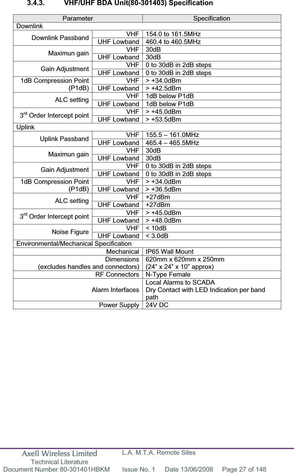
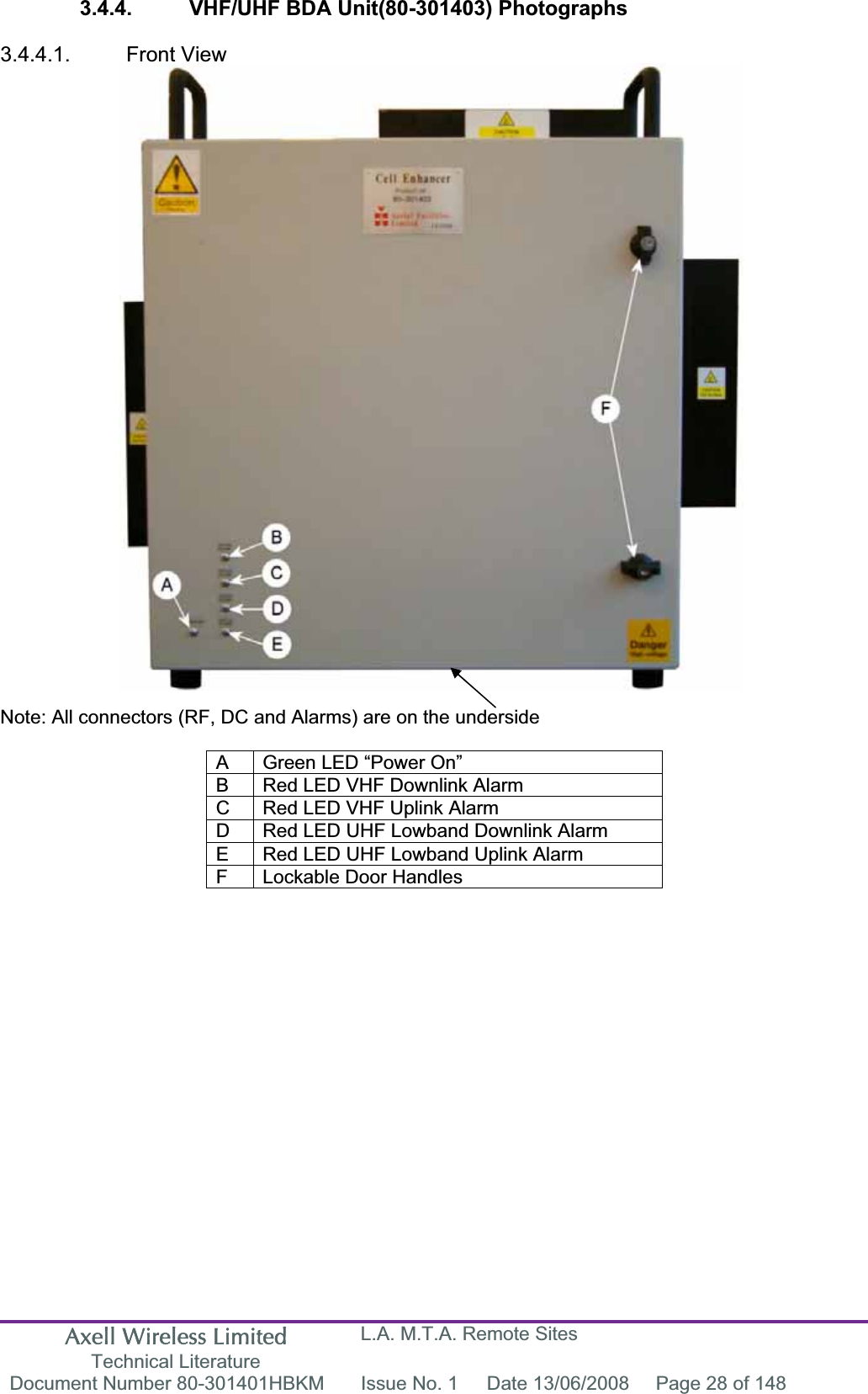
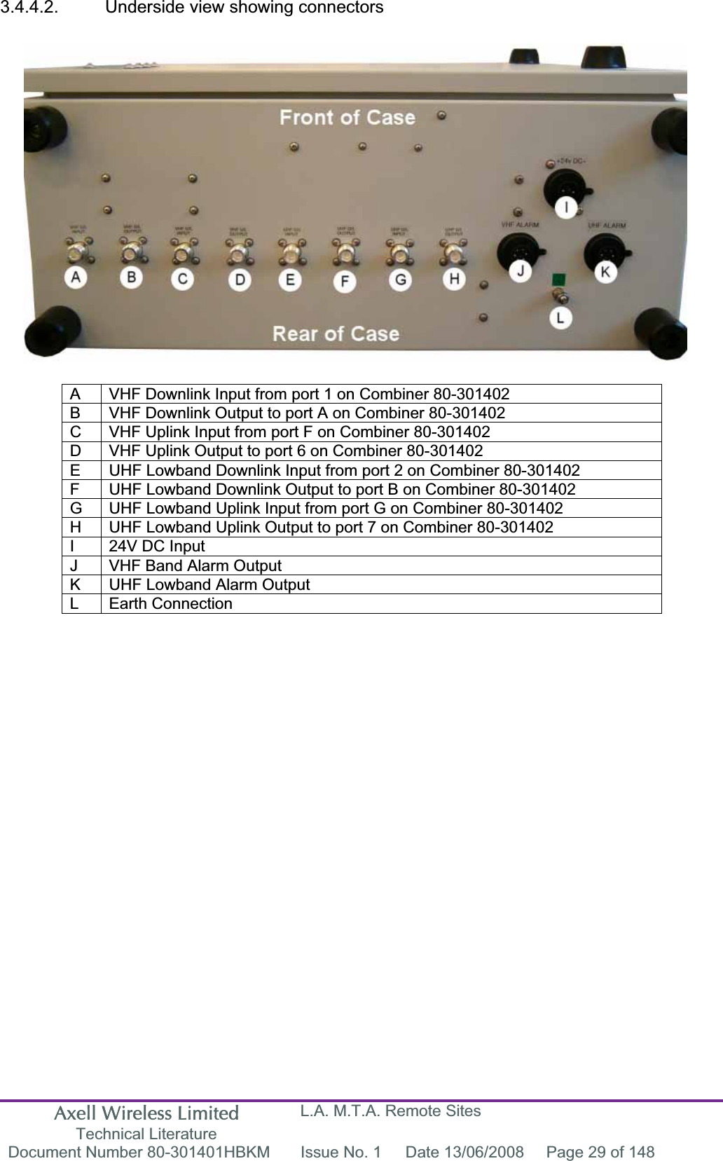
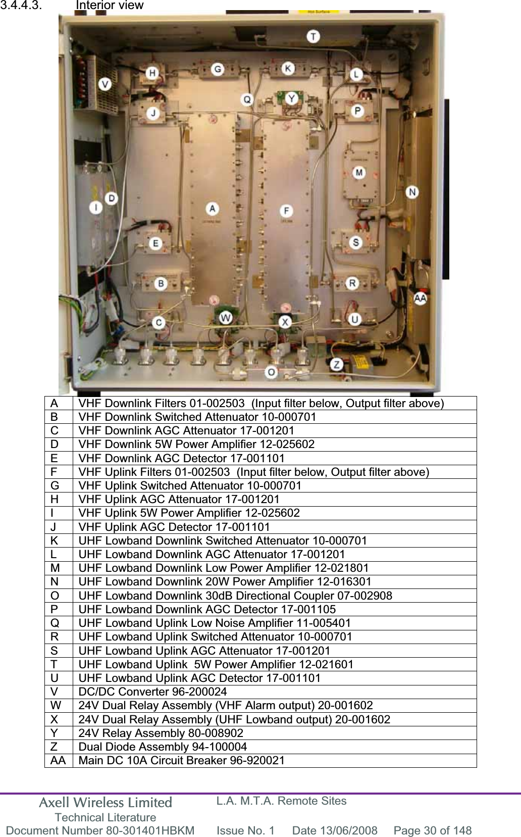
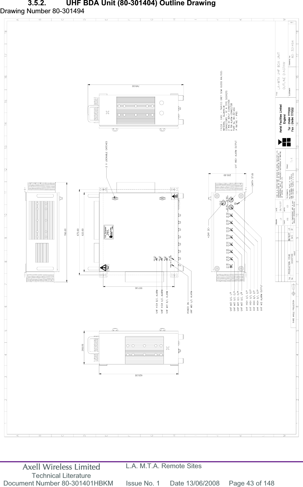
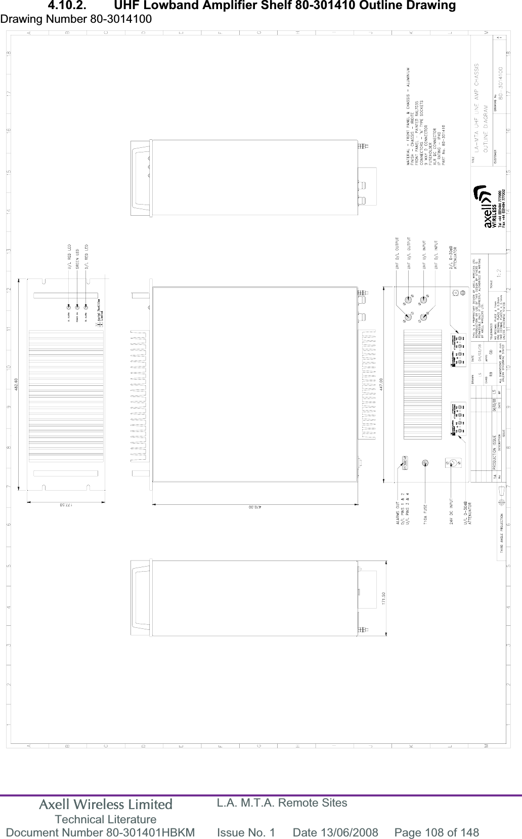
PBE Europe as Axell Wireless 80-3014SERIES 80-301403 Cell Enhancer User Manual
Axell Wireless 80-301403 Cell Enhancer
UserManual.wiki
>
PBE Europe as Axell Wireless
>
80 3014SERIES User Manual
Manual
Navigation menu
Upload a User Manual
Namespaces
Wiki Guide
HTML
PDF
Info
Views
User Manual
Discussion / Help
Navigation
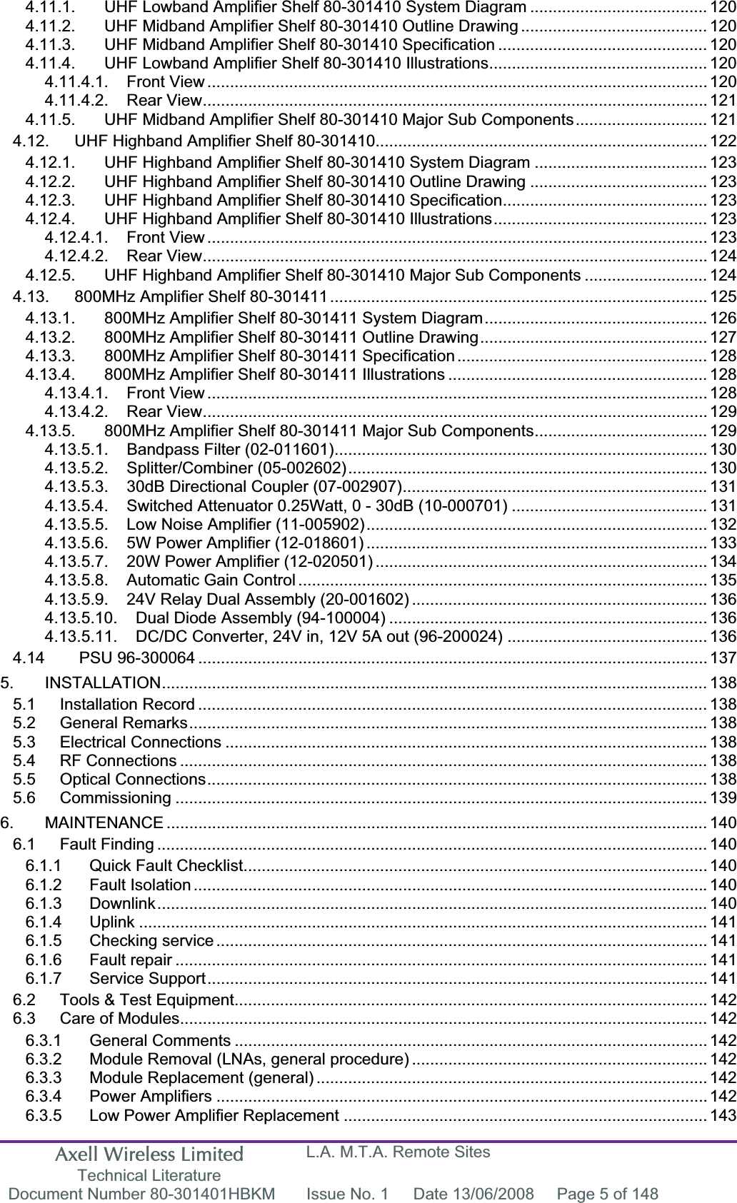


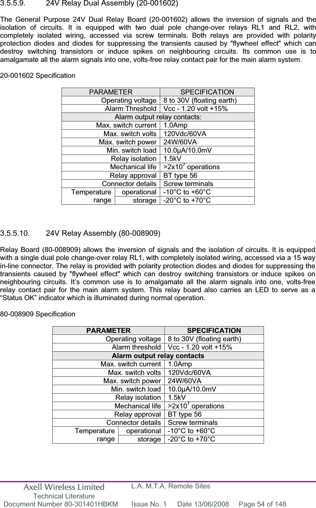
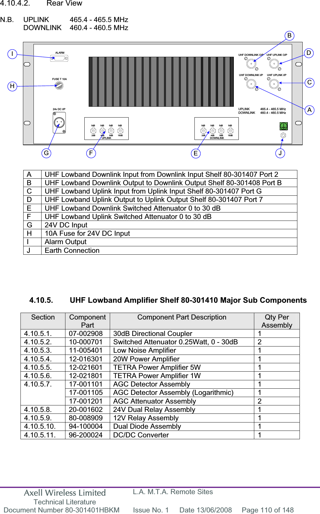
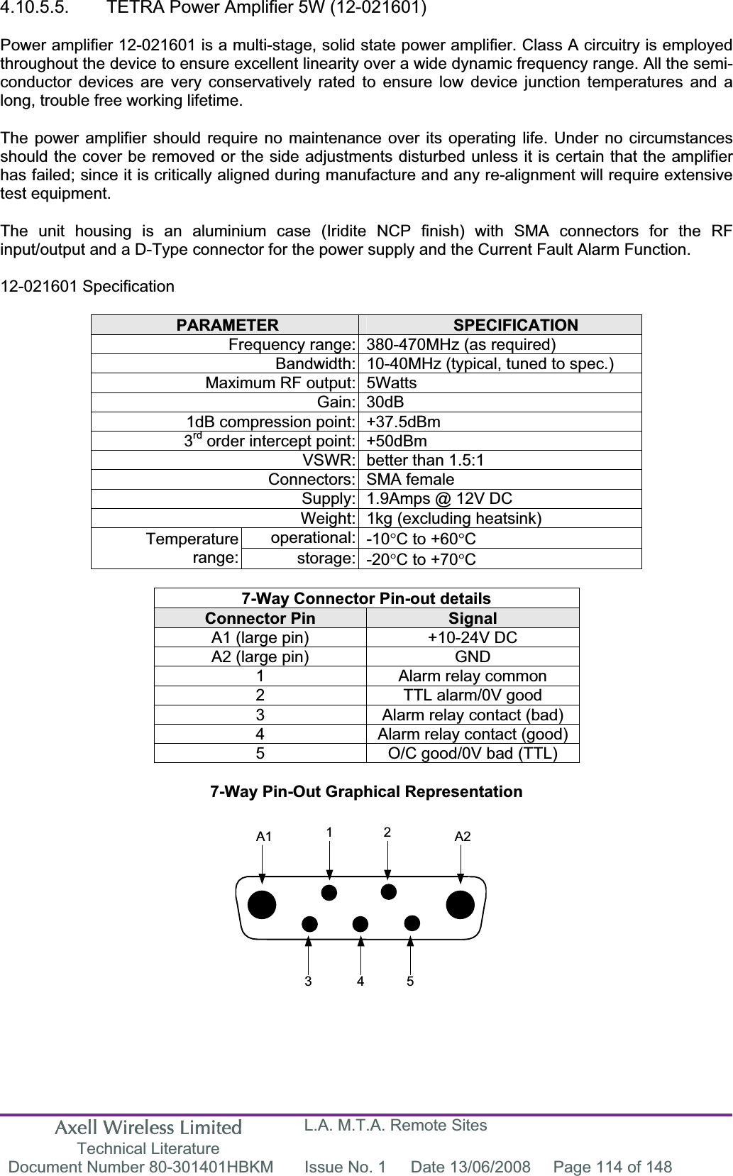
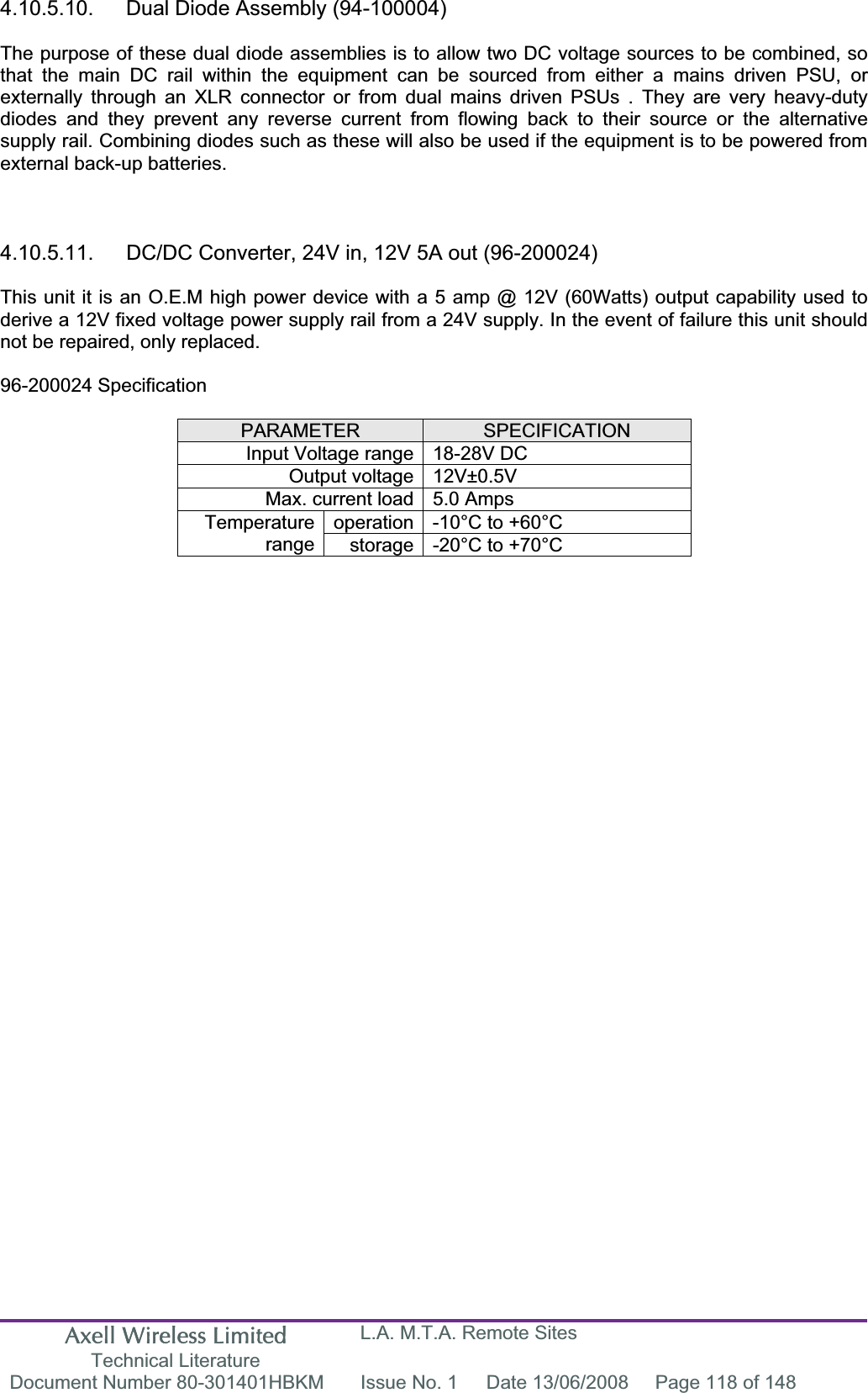


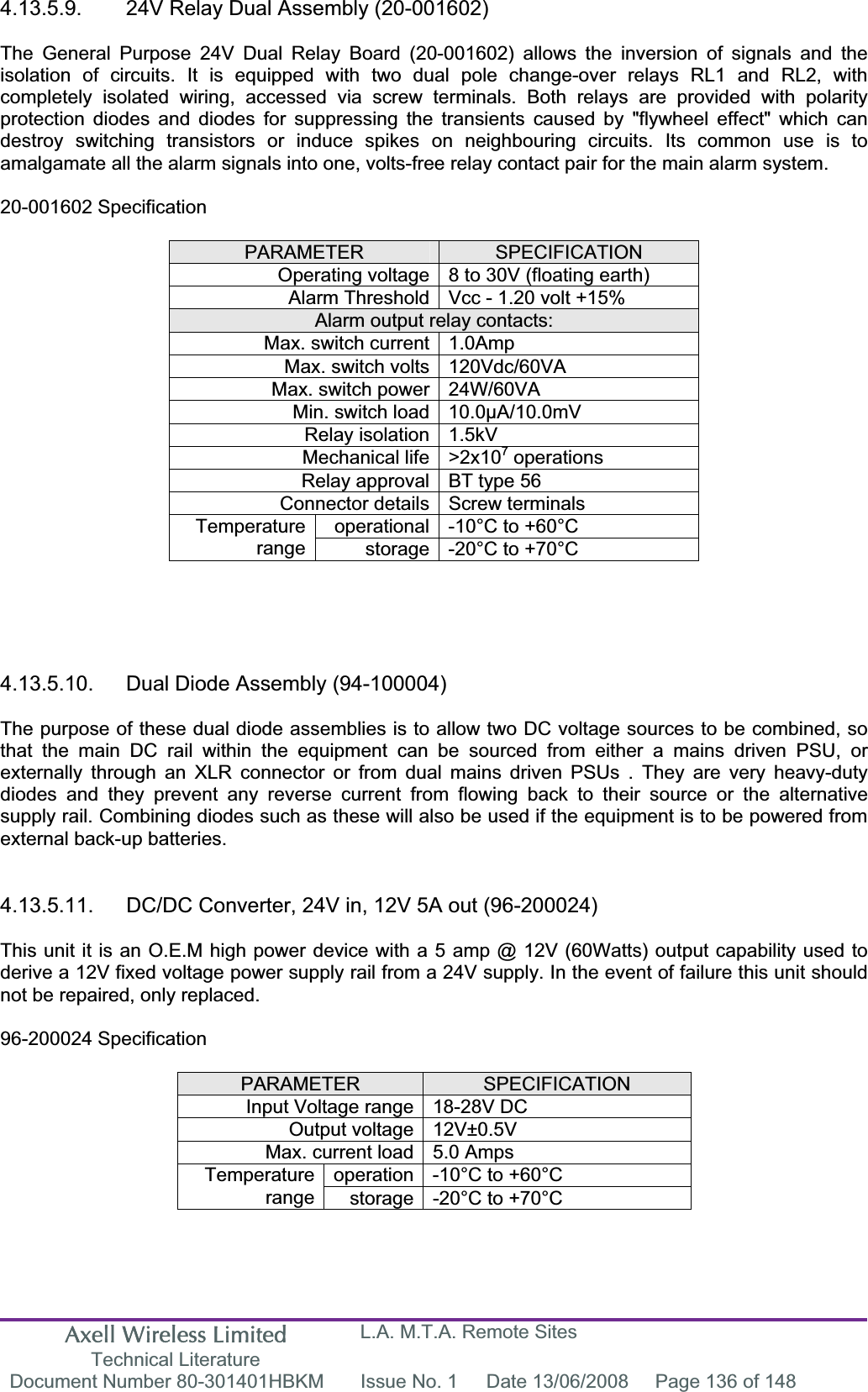
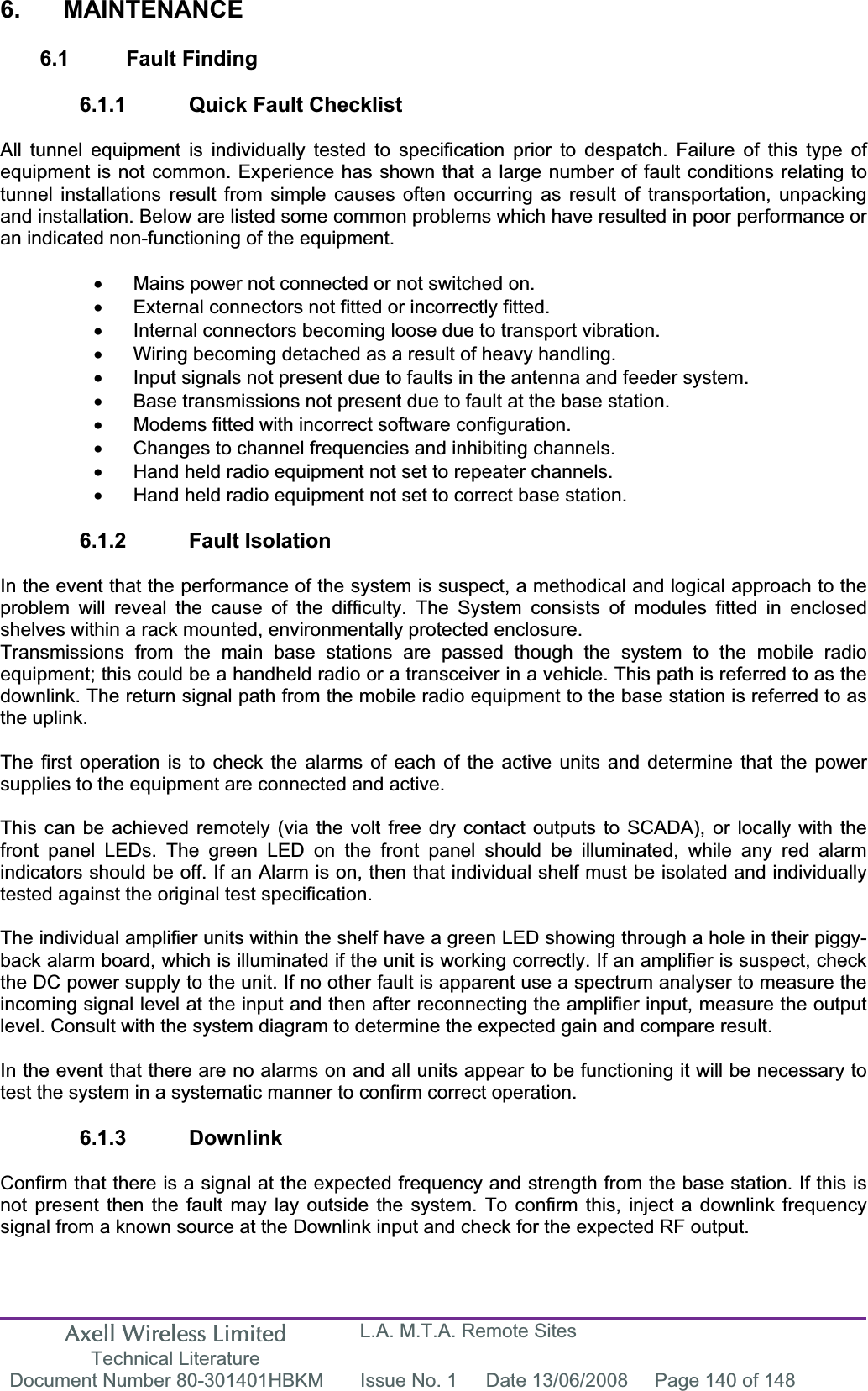
![Axell Wireless Limited Technical Literature L.A. M.T.A. Remote Sites Document Number 80-301401HBKM Issue No. 1 Date 13/06/2008 Page 145 of 148 &$;&$%/(&$;&$%/(&$7&$%/(&$%/(6),%5(237,&&$%/(/,1.&$%/(5$',$7,1*&$%/(7$33(5&283/(567$7,21%$6(75$16&(,9(50,6&+8%6),%5(0$,1+8%(;3$16,21+8%%,',5(&7,21$/$03/,),(5(%76)0+(+',$',$G%',5(&7,21$/&283/(5G%&283/(5&&5266%$1'&283/(5&283/(56- -803(5&& G%',5(&7,21$/&283/(5G%',5(&7,21$/&283/(5',5(&7,21$/&283/(53$1(/$17(11$02817('$7+,*+/(9(/',5(&7,21$/$17(11$)/$73/$7($17(11$<$*,$17(11$$17(11$65(027($17(11$81,7201,$17(11$63/,77(56$17(11$5$8%$1'3$66),/7(5&$9,7<5(621$725127&+),/7(5,62/$725+<%5,'&20%,1(5($57+678'/((.<)(('(52XWSXWVWRUHFHLYHUV56$$03/,),(50,6&G% $77(18$7259$5,$%/($*&$*& G%&21752//(5021,725,1*02'(0021,725,1*&21752//(502'(0&(//(1+$1&(5)5(48(1&<352*5$00,1*'$7$%: WRN+]&+$11(/02'8/(),%5(237,&02'8/$725),%5(237,&'(02'8/$725/2&$/26&,//$725XSWRZD\2XWSXWV'800</2$'/2&$/26&,//$72563/,77(50,6&),%5(237,&&$%/(/,1.67$1'$5')25/(9(/G%P %(/2:$&&(37$%/(6,*1$//(9(/G%P$//$,532576%&&+%52$'&$67,'(17,7<&2'(%6,&%$6,&6,7(/(9(/G%P %(/2:$&&(37$%/(6,*1$//(9(/G%P $&&(37$%/(6,*1$/ $&&(37$%/(6,*1$/&21752/&+$11(/ 5($',1*326,7,21 6,*1$/.(<67$1'$5'(;&(37)25$,5325766((%(/2:%/$'($17(11$$77(18$725),;('G%287,1&283/('+, &20/2:+<%5,'63/,77(5,1,1287287,1287%<'$7('(6&5,37,211R7+,5'$1*/(352-(&7,21$%&'()$%&'()D[7HO$HULDO)DFLOLWLHV/LPLWHG7+,6,6$35235,(7$5<'(6,*12)$(5,$/)$&,/,7,(6/7'5(352'8&7,212586(2)7+,6'(6,*1%<27+(56,63(50,66,%/(21/<,)(;35(66/<$87+25,6(',1:5,7,1*%<$(5,$/)$&,/,7,(6/7'12'(&,0$/3/$&(sPP21('(&,0$/3/$&(sPP7:2'(&,0$/3/$&(6sPP$//',0(16,216$5(,1PP81/(6627+(5:,6(67$7('&+.''5$:1$33''$7(72/(5$1&(6 6&$/((QJODQG90-000001AANTSPL 10/05/0025,*,1$/,668(3/ 3/%/$'($17(11$$''('$$ (&15)5)3/8*62&.(7),%5(237,&&211(&725)&$3&62&.(73/8*0,6&'&'&$&72'&368'&72'&&219(57(5)86(5(/$<12&/($5&217$&71&),//('&217$&7&200% *' 3/% 7(;7&255(&7,21 3/,668()&86720(5'5$:,1*1R7,7/($AFL - STANDARD SYMBOLSA.2. Key to Drawing Symbols used in this document](https://usermanual.wiki/PBE-Europe-as-Axell-Wireless/80-3014SERIES/User-Guide-960430-Page-145.png)
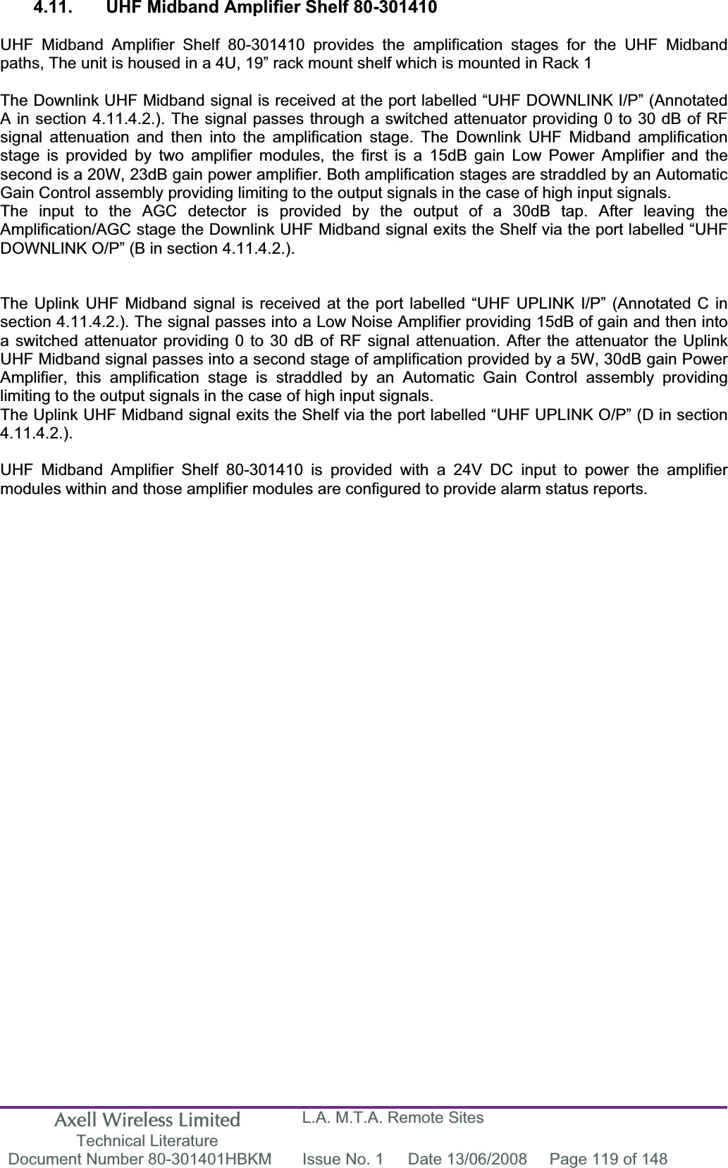
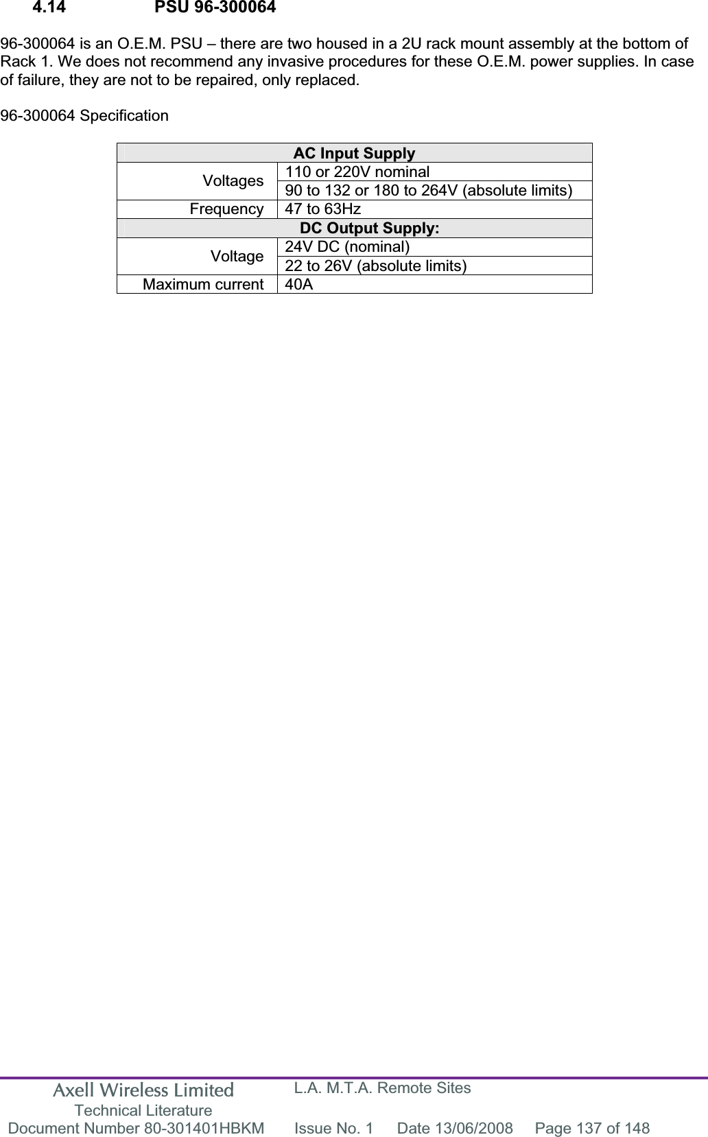
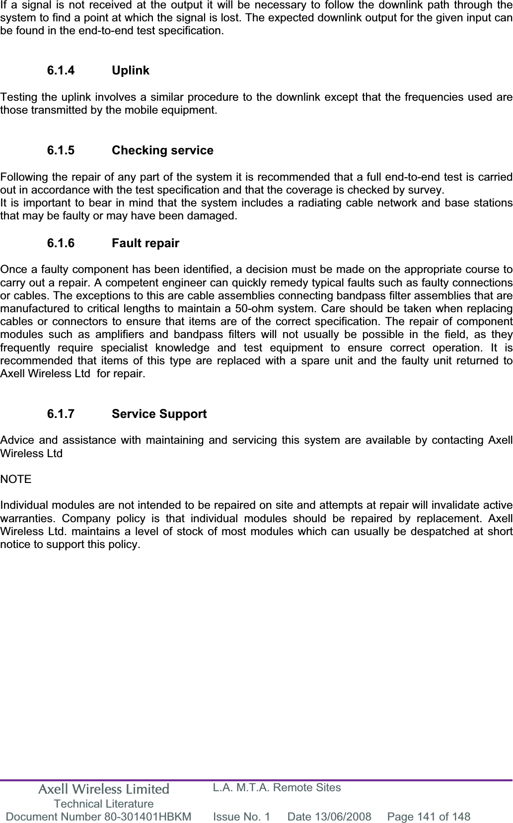
![Axell Wireless Limited Technical Literature L.A. M.T.A. Remote Sites Document Number 80-301401HBKM Issue No. 1 Date 13/06/2008 Page 146 of 148 A.3. EC Declaration of Conformity In accordance with BS EN ISO/IEC 17050-1&-2:2004 Aerial Facilities Limited Aerial House Asheridge Road CheshamBuckinghamshire HP5 2QD United Kingdom DECLARES, UNDER OUR SOLE RESPONSIBILITY THAT THE FOLLOWING PRODUCT: PRODUCT DESCRIPTION AND PART NO[S]In-Line Bi-Directional Amplifier (Wall Mount) 80-301401 In-Line Bi-Directional Amplifier (Rack Mount) 80-301406 IN ACCORDANCE WITH THE FOLLOWING DIRECTIVES: 1999/5/EC The Radio & Telecommunications Terminal Equipment Directive Annex V and its amending directives HAS BEEN DESIGNED AND MANUFACTURED TO THE FOLLOWING STANDARD[S] OR OTHER NORMATIVE DOCUMENT[S]: BS EN 60950 Information technology equipment. Safety. General requirements ETS EN 301 489-1 EMC standard for radio equipment and services. Part 1. Common technical requirements I hereby declare that the equipment named above has been designed to comply with the relevant sections of the above referenced specifications. The unit complies with all essential requirements of the Directives. SIGNEDB. S. BARTON OPERATIONS DIRECTOR DATE: 21/01/2008 Registered Office: Aerial House, Asheridge Road, Chesham, Buckinghamshire, HP5 2QD England Registered No. 4042808 (England) www.axellwireless.com](https://usermanual.wiki/PBE-Europe-as-Axell-Wireless/80-3014SERIES/User-Guide-960430-Page-146.png)